1
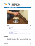
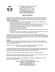
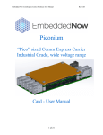
LCD-Kit05A
VGA Input LCD Kit of
12.1” TFT Color 800x600 – 18bits Display
©Copyright 2000 by ICP Electronics Inc. All Rights Reserved.
Manual first edition July 17, 2000.
The information in this document is subject to change without prior
notice in order to improve reliability, design and function and does
not represent a commitment on the part of the manufacturer.
In no event will the manufacturer be liable for direct, indirect,
special, incidental, or consequential damages arising out of the use
or inability to use the product or documentation, even if advised of
the possibility of such damages.
This document contains proprietary information protected by
copyright. All rights are reserved. No part of this manual may be
reproduced by any mechanical, electronic, or other means in any
form without prior written permission of the manufacturer.
Contents
1. Introduction ........................................................................ 2
1.1
Specifications.................................................................................. 3
1.2
What You Have............................................................................... 4
1
Introduction
2. Installation.......................................................................... 5
2.1
LCD-Kit05A Connection Layout ...................................................... 6
2.2
Dimension Drawing ......................................................................... 7
3. LCD-Kit05A Connectors .................................................... 8
3.1
LCD-05 Connection Board Layout .................................................. 8
3.1.1 LCD Connector ............................................................................... 9
3.1.2 Backlight Inverter Control.............................................................. 10
3.2
Backlight Connector...................................................................... 11
3.3
Touch Panel Power Connector ..................................................... 11
3.4
Brightness Setting Connector….................................................... 11
3.5
AV-6721 Control Board ................................................................. 11
Welcome to the LCD-Kit05A. The LCD-Kit05A is an Amorphous
Silicon TFT LCD panel with VGA input and OSD (On Screen
Display) control. It is made for the system manufacturers,
integrators, or VARs that want to provide all the performance,
quality and reliability.
The LCD-Kit05A is designed with 800 x 600 resolution and 18bits display colors, wide view angle, High Contrast and Low
Reflection to present a High Image Quality. With its compact size
(12.1”), LCD-Kit05A is also the most suitable solution for OA
Equipment, Display Terminals, and Industrial portable
Workstation LCD monitor.
The LCD-Kit05A comes with specifically designed mounting kit
for fast installation. It is also Plug and Play, can be directly and
easily connected to any VGA port.
3. Appendix .......................................................................... 12
Unpacking Precautions
LCD-Kit05A
1
LCD-Kit05A
2
1.1 Kit Specifications :
1.2 What You Have
In addition to this User's Manual, the LCD-Kit05A package
includes the following items:
Single Supply Voltage : +12V
Outline Dimensions : 294.0mm (W) x 240.7mm (H) x 61.0mm (D)
Panel Size : 12.1” Diagonal
AC-6721 User’s Manual
Active Area Size: 246.0mm x 184.5mm
LCD-Kit05A User’s Manual
Viewing Area : 247.5mm x 186.0mm
Power adapter
Display Colors : 256k Colors by the combinations of 18 bits data
AC power cord
Number of Pixels : 800 (W) x 600 (H)
VGA cable (1.8M)
Brightness : 250 cd/m2
If any of these items is missing or damaged, contact the dealer
from whom you purchased the product. Save the shipping
materials and carton in case you want to ship or store the product
in the future.
Pixel Pitch : 0.3075mm (H) x 0.3075mm (V)
Viewing Angle : Vertical = 90o, Horizontal = 110o
Contrast Ratio : 250 : 1
Surface Treatment: Anti-glare and Hard Coat
Backlight: Twin Cold-Cathode Fluorescent Lamps for sidelighting
Operating Temperature : 0~50oC
LCD MTBF : 50,000 hours
Backlight MTBF : 25,000 hours (avr.)
VGA Input
OSD built
RS232 I/F Touch Panel (option)
LCD-Kit05A
3
LCD-Kit05A
4
2.1
2
LCD-Kit05A Connection Layout
Installation
FP-2401
This chapter describes how to install the LCD-Kit05A and include
all connections description such as jumpers, connectors and
switches setting. The layout of LCD-Kit05A connectors are
shown on the next chapter. The reference manual of AV-6721
control board are separated on attached booklet. Also the
Unpacking Precautions are shown on appendix that you should
be careful with are described on the following page.
VGA INPUT
AV6721
+12VDC INPUT
A26
LCD-05
CN1
CN2
IV-16130
OSD (SELECT)
OSD (DOWN)
OSD (UP)
OSD (RETURN)
VGA
TO RS-232 (OPTION)
+12VDC INPUT
LCD-Kit05A
5
LCD-Kit05A
6
LCD-Kit05A Dimension Drawing
212.8
3
37.2
LCD-Kit05A Connectors
3.1
LCD-05 Connection Board Layout
294
225
1.1
112.5
LCD-05
CN2
CN3
CN1
CN4
CN6
CN5
240.7
2.2
LCD-Kit05A
7
LCD-Kit05A
8
• CN5: LCD OUTPUT (DF14-30P-1.25H) Connector
(connect to Panel Display)
3.1.1 LCD Connector
• CN1: 22x2 Header/2.0mm LCD Connector
(connect to LCD Control Card)
PIN NO
1
3
5
7
9
11
13
15
17
19
21
23
25
27
29
31
33
35
37
39
41
43
FUNCTION
+12V
GND
+5V
FPVEE
P0
P2
P4
P6
P8
P10
P12
P14
P16
P18
P20
P22
GND
SHFCLK
M
GND
GND
+5V
PIN NO
2
4
6
8
10
12
14
16
18
20
22
24
26
28
30
32
34
36
38
40
42
44
PIN NO. DESCRIPTION
1
GND
3
NC
5
GND
7
P19
9
P21
11
P23
13
P10
15
P12
17
P14
19
GND
21
P3
23
P5
25
P7
27
GND
29
+5V
FUNCTION
+12V
GND
+5V
GND
P1
P3
P5
P7
P9
P11
P13
P15
P17
P19
P21
P23
GND
FLM
LP
ENBKL
NC
+5V
3.1.2
PIN NO.
2
4
6
8
10
12
14
16
18
20
22
24
26
28
30
DESCRIPTION
SHFCLK
NC
P18
P20
P22
GND
P11
P13
P15
P2
P4
P6
M
+5V
GND
Backlight Inverter Control
• JP1: Backlight Inverter ON/OFF control - jumper
PIN NO.
1-2
2-3
FUNCTION
USE FPVEE
USE ENBKL
3.2 Backlight Connector
• CN2: Backlight Inverter Connector
PIN NO.
1
2
3
4
LCD-Kit05A
9
LCD-Kit05A
DESCRIPTION
Vin (+12V)
ON/OFF
GND
VR
10
• CN4: JST-2Pin/2.5mm Backlight Inverter ON/OFF Switch
PIN NO.
1
2
Appendix
DESCRIPTION
+12V
Vin
Unpacking Precautions
1-2 ON : Backlight Inverter ON
1-2 OFF : Backlight Inverter OFF
3.3
Some components on LCD-Kit05A are very sensitive to static
electric charges and can be damaged by a sudden rush of power.
Ground yourself to remove any static charge before touching your
LCD-Kit05A. You can do it by using a grounded wrist strap at all
times or by frequently touching any conducting materials that is
connected to the ground.
Touch Panel Power Connector
• CN3: Touch Panel Power Connector
PIN NO.
1
2
3
4
3.4
DESCRIPTION
+12V
GND
GND
+5V
Do not touch the inner side of LCD panel and the connector/cable
of fluorescent lamp/backlight when the power is on. The inverter
supplies HIGH VOLTAGE to these parts (~ 630Vrms).
Disconnect power supply before handling and doing connection
on LCD-Kit05A. Do not plug any connector or jumper while the
power is on. It will cause fatal damage to your LCD panel.
Make sure that every connector is connected in correct direction.
Any incorrect connection may cause smoke or burn of electrical
parts or fatal damage of your LCD panel.
Brightness Setting Connector
• CN6: Brightness VR Connector
PIN NO.
1
2
3
DESCRIPTION
Series Resistor to VCC
VR
GND
Be careful with the liquid crystal material. Do not swallow, inhale
or have skin contact with this material in case that the LCD panel
is broken and the liquid flow out. If you inhale the liquid material,
rinse your mouth immediately with water then go to see a doctor.
If you have skin contact with the liquid, wash it immediately with
alcohol. Be careful, too, with the chips of glass if the panel is
broken.
Note: Pin1 is reserved for potentiometer
3.5
AV-6721 Control Board
The AV-6721 Control Board is worked for VGA control;
all detail as feature and connection information please
refer to “AV-6721 User Manual”
LCD-Kit05A
11
For outdoor usage, an ultra-violet ray protect-lens is
recommended to apply onto LCD display. It will prevent your LCD
from strong sun-light, scratches, dust and water invasion etc.
which can cause damage to the LCD display.
LCD-Kit05A
12