1
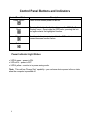
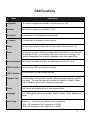
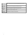
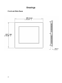
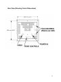
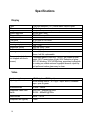
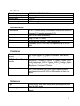
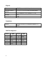
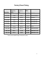
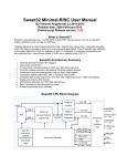
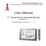
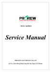
Hope Industrial Systems, Inc. User Manual 12” Panel Mount Industrial Monitor Revision C Model Numbers: HIS-ML12- _ _ _ C Table of Contents SAFETY AND REGULATORY INFORMATION.................................................................... 3 Warning .............................................................................................................................. 3 FCC Notice ......................................................................................................................... 3 CONTROL PANEL BUTTONS AND INDICATORS.............................................................. 4 Power Indicator Light Status ............................................................................................... 4 OSD FUNCTIONS ................................................................................................................. 5 INSTALLATION INSTRUCTIONS ......................................................................................... 7 Preparing for Installation..................................................................................................... 7 Installation into Panel.......................................................................................................... 8 TOUCHSCREEN DRIVER INSTALLATION ......................................................................... 9 CLEANING........................................................................................................................... 10 Resistive Touchscreen model .......................................................................................... 10 Tempered Anti-Reflective Glass Window......................................................................... 10 TROUBLESHOOTING ........................................................................................................ 11 DRAWINGS ......................................................................................................................... 12 Front and Side Views ....................................................................................................... 12 Rear View (Showing Cutout Dimensions) ........................................................................ 13 SPECIFICATIONS ............................................................................................................... 14 Display .............................................................................................................................. 14 Video ................................................................................................................................ 14 Electrical ........................................................................................................................... 15 Environmental................................................................................................................... 15 Functional ......................................................................................................................... 15 Enclosure.......................................................................................................................... 15 Physical ............................................................................................................................ 16 Compliance....................................................................................................................... 16 VGA Pin assignment ........................................................................................................ 16 FACTORY PRESET TIMING............................................................................................... 17 WARRANTY STATEMENT ................................................................................................. 18 2 Safety and Regulatory Information Warning To prevent fire or shock hazard, do not expose the unit to rain or moisture. Dangerously high voltages are present inside the unit. Do not disassemble the unit. Refer servicing to qualified personnel only. This equipment is not intended for use in critical applications where its failure to operate would create immediate life threatening circumstances. Applications including but no limited to nuclear reactor control, aerospace navigation systems and life support systems are not appropriate for this product. This product is intended to be mounted in a suitable cabinet or other enclosure. The NEMA 4, 4x or 12 ratings are applicable only when properly installed in a like rated enclosure. This product is a UL Recognized Component and must be used with a listed computer. FCC Notice This equipment has been tested and found to comply with the limits for a Class A digital device, pursuant to Part 15 of the FCC Rules. These limits are designed to provide reasonable protection against harmful interference when the equipment is operated in a commercial environment. This equipment generates, uses, and can radiate radio frequency energy and, if not installed and used in accordance with the instruction manual, may cause harmful interference to radio communications. Operation of this equipment in a residential area is likely to cause harmful interference in which case the user will be required to correct the interference at his own expense. Any changes or modifications not expressly approved by the grantee of this device could void the user’s authority to operate the device. 3 Control Panel Buttons and Indicators Control Panel Button Power On/Off Menu Select + Description Press to turn monitor power on and off. Pressing this button the first time brings up the OSD (On Screen Display) menu. Once inside the OSD menu, pressing this button again selects the highlighted function. Use these buttons to navigate within the OSD and to increase/decrease function values. Select - Power Indicator Light Status • LED lit green – power is ON. • LED not lit – power is OFF. • LED lit yellow – monitor is in power saving mode. *Note: This unit has “Energy Star” capability – you can leave device power in the on state when the computer is powered off. 4 OSD Functions Menu Description Brightness 101 scales of brightness are available to choose from (0 to 100) Contrast 256 scales of contrast are available (0 to 255) H. Position For adjustment of the display’s horizontal position. V. Position For adjustment of the display’s vertical position. Phase 32 scales are available to adjust the focus and clarity of the display (0 to 31). Clock This function provides a frequency-tracking feature that allows the user to have better stability and clarity. Increasing the Clock value can be up to 64 settings. The number of decreasing Clock (minus) is dependent on the video signal timing. Auto Adjustment This function will adjust the display size automatically to fit the full screen. OSD H. Position For moving the OSD menu window horizontally. OSD V. Position For moving the OSD menu window vertically. Graphics Text Provides ability for the operator to choose a display that allows maximum graphics text quality. The resolution selection can either be 640x400 or 720x400. Please refer to Standard Timing Table for different timing modes. Recall Will force all adjusted parameters to factory-preset values. Language Five OSD language options are available: English, German, French, Spanish and Italian. Color Temp. Push the (+ -) buttons to select different color temperatures. 9300 – CIE coordinated Color Temperature of 9300ºK 6300 – CIE coordinated Color Temperature of 6500ºK 5 USER – Three colors (Red, Green, Blue) can be adjusted from the OSD menu. Save + Exit Saves the values of this setting and exits the OSD menu function. Brightness 101 scales of brightness are available to choose from (0 to 100) Contrast 256 scales of contrast are available (0 to 255) H. Position For adjustment of the display’s horizontal position. 6 Installation Instructions Preparing for Installation Important! Perform the following steps BEFORE Installation of the monitor into the panel. 1. Ensure that sufficient power is available. 2. Ensure that sufficient space is available to allow for proper air flow into and out of the unit. 3. Ensure that the air temperature around the unit (top and bottom) will not exceed the rated specifications of the unit. • The maximum rated temperature of the HIS-ML12 is 50°C (122°F) • Remember that heat rises – the temperature at the top of the cabinet will be much hotter than at the bottom when the air is not circulating. • Also, remember that even though this product is designed to operate at 50° C, the life span of any electronic device is shortened when it is consistently operated at high temperatures. Therefore it is wise to take steps to keep the temperature of the ambient air around the unit as low as possible. 4. Ensure that the ambient humidity of the air around the unit does not exceed the rated specifications for the unit. • The maximum rated humidity for the HIS-ML12 is 90% non-condensing 7 Installation into Panel 1. Refer to the drawing below. 2. Locate position in panel for mounting of the monitor. Ensure that there is adequate space begin the panel. Allow extra space (0.5 in. behind and on each side) for air ventilation. 3. Cut a rectangular hole in the panel. Clean and deburr. Dimensions: 12.12” (308mm) W x 10.35” (263mm) H ; +/- .020” 4. Separate the rear collar from the unit by removing the 8 nuts. 5. Insert the unit into the front of the panel and re-attach the collar. 6. Tighten all 8 nuts to a torque of 24 inch-pounds to assure a water-tight seal between the poron bezel gasket on the monitor and equipment panel. HIS will not assume liability for damage to internal electronics due to improper installation. 8 Touchscreen Driver Installation The enclosed CD-ROM contains documentation and drivers for all major operating systems. To be sure you have the most current information, check the following Internet addresses: http://HISmonitors.com/Touchscreen_Drivers.htm 9 Cleaning CAUTION! DO NOT USE ABRASIVE MATERIALS SUCH AS PAPER TOWELS OR DIRTY SHOP RAGS ON THE DISPLAY AS IT WILL SCRATCH THE PROTECTIVE COATING. ALWAYS USE A SOFT CLOTH, PREFERABLY MADE OF COTTON. Resistive Touchscreen model Any standard glass cleaner can be used to clean the touchscreen. Always spray the glass cleaner on the cloth or towel and then clean the touchscreen. Glass cleaner sprayed directly on the monitor could possibly leak inside a non-sealed unit and cause damage. Vinegar or ammonia will not hurt the touchscreen. Again, spray the cloth and then clean the touchscreen. Tempered Anti-Reflective Glass Window Use any standard glass cleaner as long as there is no abrasive or oily content. The anti-reflective coatings are physically part of the surface of the glass and resist degradation to the Military Specifications. 10 Troubleshooting Blank Screen After installing the power adapter and connecting I/O cable to a PC, the monitor displays a blank screen. • • • Press the power button and check to see if the power LED is lit. If the LED turns green, make sure the PC is powered on. Make sure all cables are connected. If the LED turns orange, check to see if the PC is in the power saving mode by pressing any keys on the keyboard. Rolling Screen • • • • • Change PC display resolution to 800x600 at 60hz. Unplug the power adapter to monitor, then plug it in again. Press monitor power button again. Reset the monitor to the original factory setting. Activate the “Auto Adjust” function in the OSD menu. • • Activate the “Auto Adjust” function in the OSD menu. Make sure the PC display resolution is not set greater than 800x600 at 75hz. Make sure the PC display resolution matches one of the factory preset timings in this manual. Change the PC display resolution to 800x600 at 60hz. Reset the monitor to the factory setting. Unstable Screen • • • Screen is not perfect • • • • Activate the “Auto Adjust” function in the OSD menu. Make sure the PC display resolution matches one the factory preset timings shown in this manual. Recall factory setting. Refer to panel controls and OSD functions in this manual. Fine tune the picture by performing the following adjustments in this order – pitch, phase, and position. Refer to OSD functions in this manual. 11 Drawings Front and Side Views 12 Rear View (Showing Cutout Dimensions) 13 Specifications Display Type Size Image size Native resolution Plug and Play Minimum resolution Pixel pitch Number of colors Viewing Angle (Hori/Vert) Brightness (white) Contrast ratio Back light Screen protector (when not shipped with touchscreen) Thin-film transistor (TFT) Active Matrix Liquid Crystal 12.1” diagonal 9.7” (246mm) W x 7.3” (184.5mm) H SVGA (800 x 600) DDC1/2B compatible 640 x 350 0.3075mm x 0.3075mm 262,144 130° / 100° 2 200 nits (cd/m ) max 500:1 (typical) Two CCFTs (Cold Cathode Fluorescent Tube); 50,000 hours, half-life; replaceable Tempered glass to ANSI-Z97.1 SPEC; AR coated on both sides; 98% Transmission of light; 99% Reduction of glare; 53% UV blocking; 30% NIR Blocking; proprietary hydrophobic coating on outside reduces fingerprint smears, repels liquid spills and makes glass easy to clean. Video Input connector Input signal format HD-15 (optional BNC input) RGB Analog video 0 – 0.7V p-p – sep V and H, combined sync, sync on green Horizontal scan 31kHz – 38kHz Supported Video Standards Std VGA – 640x480 @ 60Hz SVGA – 800x600 @ 60Hz Vertical scan 60Hz – 75 Hz Response rate (typical) 10ms 14 Electrical Power Adapter Input Power adapter output Monitor input Power consumption Power management 100VAC – 240VAC, 50-60 Hz 12VDC @ 2.5 amps 12VDC Approximately 20 watts DPMS/energy star, < 5W Environmental Temperature Humidity Shock Vibration Altitude 0-50°C (consult factory for installation instructions when continuous 24/7 operation exceeds 40°C) 20% to 90% non-condensing 30g (1/2 sine, 11 msec.) 0.006 inch p-p 15-57Hz, 1.0g 57-640Hz sine Operating: up to 10,000 feet; Non-operating: up to 40,000 feet Functional Panel controls (rear access) DC Power Switch, DC Power-On Indicator, Menu Button, Plus (+) and Minus (-) Buttons OSD (On Screen Display) controls Brightness, Contrast, H. Position, V. Position, Phase, Clock, Auto Adjustment, OSD H. Position, OSD V. Position, Graphics Text, Recall, Language, Color Temp., Save + Exit, Brightness, Contrast, H. Position Touch screen option Elo Touch systems AccuTouch 5-wire resistive system; emulates a mouse; RS-232 or USB interface to host computer Enclosure Type Panel rating Panel mount; rear collar compresses gasket against panel, held by 8 M5 studs NEMA 12/4/4X (with proper installation) – built to IP65 standards 15 Physical Depth Bezel Front bezel outside dimensions Cutout dimensions 1.6” (2.5” at connectors) behind panel maximum Stainless Steel 13.3” W x 11.6” H x 0.236” thick (not including gasket) Net weight 8 lbs. Shipping weight 13 lbs. 12.12” (308mm) W x 10.35” (263mm) H ; +/- .020” Compliance Electrical UL 60950 3rd Edition, cUL recognized component; FCC Class A RoHS Environmental VGA Pin assignment Pin No. 1 2 3 4 5 6 7 8 16 Signal Red Green Blue Ground Ground Ground Ground Ground Pin No. 9 10 11 12 13 14 15 Signal No pin Ground Ground SDA H. sync V. sync SCL Factory Preset Timing Resolution 640 x 350 Horizontal Frequency (KHz) 31.469 Vertical Frequency (Hz) 70.087 640 x 400 31.469 640 x 480 Pixel Clock (MHz) Mode 25.175 VGA-350 70.087 25.175 VGA-400-GRAPH 31.469 59.940 25.175 VGA-480 640 x 480 37.861 72.809 31.500 VESA-480-72Hz 640 x 480 37.500 75.000 31.500 VESA-480-75Hz 720 x 400 31.469 70.087 28.322 VESA-400-TEXT 800 x 600 35.156 56.250 36.000 SVGA * 800 x 600 37.879 60.317 40.000 VESA-600-60Hz * 800 x 600 48.077 72.188 50.000 VESA-600-72Hz * 800 x 600 46.875 75.000 49.500 VESA-600-75Hz * Factory recommended timings for best picture quality 17 Warranty Statement Who is Covered? This warranty covers the purchaser of this product only and is not transferable without our written consent. What Does This Warranty Cover and What is the Period of Coverage? We warrant this product to be free from defects in material and workmanship, subject to the conditions set forth below. This warranty remains in force for a three-year period beginning on the date we invoice you for the product. If HIS repairs or replaces a product under warranty, its warranty term is not extended. What Will We Do to Correct Problems and How Do You Get Service? We will repair or replace (at our sole option) any part of the unit which proves to be defective. Replacement parts may be new or refurbished and will meet the same specifications of the original parts or unit. We will return the product to you by the shipping method we choose in the U.S.A. at our expense. You must pay for shipments to locations outside of the U.S.A. In order to receive warranty service you must get prior approval from HIS. To request warranty service you can telephone us at 678-762-9790 or send an email to [email protected]. If we determine that warranty service is needed we will give you a Return Material Authorization (RMA) number. This RMA number must be conspicuously marked on the outside of the shipping box. HIS will not accept shipments not accompanied by the RMA number. You must ship or deliver the product to HIS Freight prepaid. What Does This Warranty Not Cover? This warranty does not cover equipment which has been damaged due to misuse, abuse or accident such as: operating the equipment outside of published specifications; displaying fixed images for long periods of time resulting in afterimage effects; improper or unauthorized repair by anyone other than HIS or a service agency authorized by HIS to perform such repairs; fire, flood, “acts of God”, or other contingencies beyond the control of HIS. HIS’ responsibility for malfunctions and defects in hardware is limited to repair and replacement as set forth in this warranty statement. HIS shall not be liable for direct, indirect, incidental, consequential, or other types of damages resulting from the use of any HIS product other than the liability stated above. These warranties are in lieu of all other warranties express or implied, including, but not limited to, the implied warranties of merchantability or fitness for a particular purpose. Some states do not allow the exclusion of implied warranties or the limitation or exclusion of liability for incidental or consequential damages so the above exclusions or limitations may not apply to you. You are cautioned that the performance of this product can be affected by many factors, such as system configuration, software, application, and operator control of the system. It is your responsibility to determine suitability of this product for your purpose and application. 18 (This page left blank.) 19 Hope Industrial Systems, Inc. 1325 Northmeadow Parkway Suite 100 Roswell, GA 30076 www.HISmonitors.com Publication ML12C July, 2006 20 2006 Hope Industrial Systems, Inc.