1
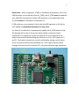
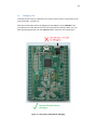
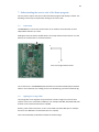
2 Please note – when using the XL_STAR for USB device development, via J1 (the USB connector on the top side of the XL_STAR), the XL_STAR must be powered via a USB cable connected to J6 (the USB connector on the underside of the XL_STAR) before a USB cable is connected to J1. If USB cables are not connected in this order the USB regulator on U1 will be over loaded and permanent damage to U1 may occur. For those of you who wish to permanently modify the XL_STAR board so that this damage will not occur the picture below details a relatively simple modification. In summary a via next to capacitor C1 on the top side of the board must be drilled out breaking the connection of the +3.3V supply to C1 and C2. The break in connectivity can be confirmed by placing a multi‐meter set for resistance measurement between the +3.3V supply (top left plated through hole) and the left hand pad of C2, which should show high impedance.