1
LightingDemo
Controlling High Power LEDs using DMX512 and DALI
2
Copyright © 2009 MicroAPL Ltd.
All rights reserved. No part of this manual may be adapted or reproduced in any form without the
prior written approval of MicroAPL Limited.
MicroAPL welcomes comments and suggestions. These and any error reports should be sent via our
web site: http://www.microapl.co.uk/lightingdemo
MicroAPL is a trademark of MicroAPL Ltd.
Freescale is a registered trademark of Freescale Semiconductor, Inc.
All other tradenames, trademarks and registered trademarks are the property of their respective
owners.
Version 1.0.6 December 2009
Simon Marsden, MicroAPL Ltd
3
Table of Contents
Introduction ..................................................................................................................................... 5
Configuring the Boards .................................................................................................................... 6
Choice of DMX512 or DALI protocol ............................................................................................. 7
Specifying the type of LED ............................................................................................................ 8
Specifying a unique DMX512/RDM UID ....................................................................................... 8
Installing the LightingDemo Application .......................................................................................... 9
Requirements .............................................................................................................................. 9
Installing from CD ........................................................................................................................ 9
Installing the LightingDemo application manually ........................................................................ 9
Installing the USB Driver manually ............................................................................................... 9
Using the LightingDemo Application .............................................................................................. 13
Device Discovery ........................................................................................................................ 13
Failure to see the Controller Board ............................................................................................ 13
Failure to see the Slave Boards .................................................................................................. 14
Device control ............................................................................................................................ 15
sRGB Colour Space Control ........................................................................................................ 16
CIE1931 Colour Space Control .................................................................................................... 16
Direct Control ............................................................................................................................ 19
Sensor Display ............................................................................................................................ 20
Diagnostics ................................................................................................................................. 21
Software Overview ........................................................................................................................ 23
Documentation .......................................................................................................................... 23
Memory Footprint ..................................................................................................................... 24
DMX512 and RDM implementation on the Controller and Slave Boards .................................... 25
Endian Dependencies ................................................................................................................. 26
DALI implementation on the Controller and Slave Boards.......................................................... 27
Controller Board software ............................................................................................................. 29
MQX on the controller board ..................................................................................................... 30
Debugging information for the controller board ........................................................................ 30
C Pre-processor Definitions for the controller board .................................................................. 30
Using DMX512/RDM on the Controller Board ................................................................................ 32
4
Initialising the DMX_HANDLE ..................................................................................................... 32
Initialising the hardware ............................................................................................................ 32
RDM Discovery........................................................................................................................... 32
Allocation of DMX512 Start Addresses ....................................................................................... 34
Sending data in DMX512 NULL Start-Code packets .................................................................... 34
System Information Packets (SIPs) ............................................................................................. 34
Changing the RDM personality of a slave device ........................................................................ 35
Specifying CIE1931 Colour Space values ..................................................................................... 35
Sending other RDM commands.................................................................................................. 35
Example Code ............................................................................................................................ 37
Using DALI on the Controller Board ............................................................................................... 40
Initialising the DALI_HANDLE ..................................................................................................... 40
Initialising the hardware ............................................................................................................ 40
DALI Discovery ........................................................................................................................... 40
Specifying CIE1931 Colour Space values ..................................................................................... 41
Sending other DALI commands .................................................................................................. 41
Example Code ............................................................................................................................ 43
Slave Board Software ..................................................................................................................... 46
The ansifs.lib Library .................................................................................................................. 46
C Pre-processor Definitions for the slave board ......................................................................... 46
Mini-DALI version of the slave software ..................................................................................... 47
LED Control ................................................................................................................................ 48
XML Descriptions of LED Types .................................................................................................. 48
Regenerating the XML File ......................................................................................................... 50
Colour Balancing ........................................................................................................................ 51
Adjusting Duty Cycles ................................................................................................................. 52
Temperature Regulation ............................................................................................................ 53
5
Introduction
Safety Warnings
Do not look directly at high-brightness LEDs unless they are fitted with a suitable
diffuser. Some makes of LED are very bright and could cause damage to your eyes if
you look at them for a long period.
The high-power version of the High Brightness LED Driver board uses large currents.
For example the Luminus PhlatLight CBM-380 can take up to 32A. Handle with care.
This application note is written to accompany the Freescale Semiconductor, Inc reference design for
high-brightness LED control, and describes an application called LightingDemo.
LightingDemo allows you to control one or more high-brightness LEDs using a PC. It demonstrates
how the Freescale Lighting Controller board can be used to control one or more LED slave boards
using either of two industy-standard protocols, DMX512/RDM and DALI.
Full source code of the software running on the controller and LED boards is provided.
The application note covers the following topics:
Configuring the boards and installing the LightingDemo application on the PC
Using the LightingDemo application.
Detailed discussion of the source code of the software running on controller and LED boards.
6
Configuring the Boards
Note: Don’t connect the controller board to the PC yet. Because the act of connecting the board will
cause the PC to look for new driver software, this step is best delayed until the section “Installing the
LightingDemo Application”.
The LightingDemo application requires the following:
A PC running Windows XP or Windows Vista 32-bit editions, with .NET framework version 3.0
or later installed
One Freescale MCF52259 Lighting Controller (the controller board)
One or more Freescale High-Brightness LED Driver boards (the slave boards).
The boards must have the correct software installed and be jumpered correctly (see below).
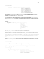
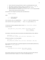
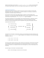
A typical DMX512 configuration is shown below. Note that the Controller board gets its power from
the USB connection and does not require a separate power supply, and that the last slave board on
the DMX512 link requires a terminator.
Typical DMX512 Configuration
PC
USB cable
DMX cable
DMX cable
Terminator
Controller
Board
Slave Board
Slave Board
12V Power
Supply
7
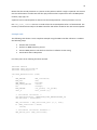
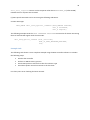
A typical DALI configuration is shown below. In this case, the controller board requires an external
12V power supply to drive the DALI link.
PC
Typical DALI Configuration
DALI cable
USB cable
Controller
Board
Slave Board
12V Power
Supply
Slave Board
12V Power
Supply
Choice of DMX512 or DALI protocol
The LightingDemo application allows you to control the high-brightness LEDs using either the
DMX512 or DALI protocol. The choice of which protocol to use is determined by the settings of
switches on the Controller and Slave boards.
Controller Board:
Set the DMX/DALI switch appropriately
Slave Board:
Set the Mode switch as follows:
1
:
DALI
2
:
DMX512
Notes: This choice determines whether the controller board talks to the slaves through the DMX or
DALI interface. It does not affect the connection between PC and controller board, which uses a
simple proprietary message format sent over USB.
For demonstration purposes you can connect the boards together using both DMX512 and DALI
cabling. You can switch between DMX and DALI at any time without re-booting the boards or relaunching the LightingDemo application, simply by changing the switches on the boards. After
changing the switches, repeat the device discovery process using the “Repeat Search for Devices”
button in the LightingDemo application’s Devices window.
8
Specifying the type of LED
There are two ten-way switches marked 10’s and 1’s on the slave boards. Together these allow you
to specify one of 99 different types of high-brightness LED. At the time of writing the possible values
are:
1
:
Philips Lumileds Luxeon Rebel RGB + Cool White
2
:
Luminus PhlatLight CBM-380
This information is used to determine how to drive the LEDs: maximum current, colour balance, etc.
Note: The values above correspond to the <id> tag in the XML descriptions of LED characteristics
stored on the slave board.
Specifying a unique DMX512/RDM UID
Every board which implements the Remote Device Management (RDM) protocol extension to
DMX512 must have a Unique ID (UID). The UID is a 48-bit number consisting of a 16-bit ESTAassigned Manufacturer ID and a 32-bit device ID.
If you are building a product based on the Freescale Reference Design you should complete the
following steps:
1. Apply to ESTA for a unique Manufacturer ID
2. Ensure that every device you manufacture has a unique device ID.
Two devices with the same UID on the same DMX512 lighting circuit will fail to operate properly.
For the Reference Design, the device portion of the UID on the slave boards is assigned a value from
0 - 9 based on the ten-way switch labelled 100’s. You must make sure that every board has its 100’s
switch set to a different value.
For the Reference Design, the controller UID is hard-coded.
Note: Use of the 100’s switch to assign the slave board UID is done here for
convenience, as is the hard-coded UID used by the controller board.
For a shipping product it’s not an acceptable solution; you need to ensure that each
device manufactured has a unique ID stored in Flash.
9
Installing the LightingDemo Application
Requirements
The LightingDemo application runs under 32-bit versions of Windows XP or Vista. It requires the .NET
framework version 3.0 or later, which is always present under Vista but may require installing under
XP.
Installation of the LightingDemo application consists of two parts: installing the application and
installing the USB driver. The easiest way is to install from CD using the following steps:
Installing from CD
1. Start with the controller board not connected to the PC - i.e. do not plug in the USB cable at
this stage.
2. Insert the installation CD. This should cause the installer program to launch automatically
3. When prompted to do so by the installer, connect the USB cable. This should cause Windows
to recognize that new hardware has been attached.
4. Windows will locate the USB device driver on the CD and install it automatically
5. Continue with the installation of the application. If you do not have the .NET framework
installed, the installer will prompt you to install it. You need to be connected to the net if a
download of the .NET framework installer is required.
Installing the LightingDemo application manually
If you are installing the LightingDemo application from an electronic download instead of CD, you
can run the installer by launching setup_freescale_lcb.exe
Installing the USB Driver manually
When you connect the USB cable, Windows will recognize that new hardware has been attached and
will look for a suitable driver. If you are installing from CD the process should be automatic, but if
you are installing from disk you need to use the following steps:
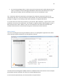
10
1. Windows will ask whether you want to install the driver:
2. If you are installing from a downloaded package, Windows will first look in standard
locations for the driver before giving you the opportunity to specify the driver folder.
This may take several minutes.
11
3. Eventually you will be prompted to provide a location for the driver software manually:
4. Specify the driver folder in the LightingDemo package:
You should be prompted whether to install the driver:
12
5. You can verify that the Controller board has been recognized by checking the Windows
Device Manager
13
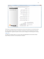
Using the LightingDemo Application
Device Discovery
When the LightingDemo application is launched it will first attempt to contact the Controller board
via the USB connection.
Assuming that all is well, the application will instruct the Controller board to begin a search for
connected devices using either the DMX512 or DALI discovery process. Discovery should complete
rapidly for DMX512 but may take a few seconds for DALI. After discovery is complete you will see a
list of the connected devices:
To begin using a device, select it from the list on the left. You can switch between devices at any
time.
Failure to see the Controller Board
If the LightingDemo application is unable to contact the Controller board via the USB connection you
will see the following dialog:
14
Try unplugging the USB cable and then reconnecting it, which should cause Windows to recognize
that it has a Controller board connected. If the problem persists you need to check whether the USB
driver installed correctly. See the section “Installing the USB Driver manually” for more information.
The simulator is for use in situations where you don’t have a controller board but are interested in
evaluating the LightingDemo software. The controller board and slave boards are simulated in
software.
The simulator allows you to choose between DMX512 and DALI protocols, investigate the operation
of the LightingDemo application and view the DMX512/DALI traffic sent over the simulated
connection between controller and slaves.
Failure to see the Slave Boards
If the LightingDemo application can see the controller board but there is a problem with the slave
boards, the list of devices will be empty:
15
You should verify that the slaves are connected properly, and that the Mode switches on the slave
boards are set correctly for DALI (Mode=1) or DMX512 (Mode=2).
In the case of DMX512 you should also:
(a) Make sure that the chain is properly terminated. The last slave board should have a
terminator installed on JP1, and the other slaves should have the terminator removed.
(b) Make sure that the switch on the slave board marked ‘100s’ is set to a unique value for
each board present.
In the case of DALI, make sure that the controller board has the DALI power supply connected. The
board itself is bus-powered from the USB connection, but the DALI interfaces requires a separate
power supply.
Device control
Once the device discovery process has successfully completed, you can select a device from the list
shown at the left of the LightingDemo window. Depending on which protocol you are using, the
following options are present
sRGB Colour Space control
CIE 1931 Colour Space control
Direct control
For DMX512 this option allows you to control the individual colours of a multi-colour LED
directly.
This option is not present for DALI.
Sensor display
For DMX512 this option allows you to monitor the on-board sensors on the slave board.
This option is not present for DALI.
The last two options are not available for DALI because the protocol is much less sophisticated. Using
DMX512, multi-byte RDM packets can be exchanged with a slave, for example to inquire about
sensor data. By contrast DALI is limited to two-byte messages from controller to slave and one-byte
replies.
16
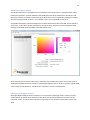
sRGB Colour Space Control
The sRGB Colour Space is probably the most familiar to users because it’s a standard colour space
used with computers. A colour defined in the sRGB space has three components: Red, Green and
Blue. Each of these is typically represented by an 8-bit value in the range 0-255, leading to a 24-bitsper-pixel representation of colour. For example a ‘pure’ red is specified as (255, 0, 0)
The sRGB Colour Space could be thought of as a three-dimensional cube, with Red, Green and Blue
as the axes. In the colour picker show below, the square area represents a slice through the cube
showing all possible Green and Blue values when Red = 255.
Note that the primary colours (Red, Green and Blue) of the sRGB colour space are not the same as
the Red/Green/Blue primaries used by a typical high-brightness LED. In order to achieve a given sRGB
colour using the LED primaries, software has to perform a colour transformation.
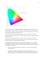
CIE1931 Colour Space Control
Although sRGB is widely used for computers, it’s not ideal for specifying colours. There are many
colours which are visible to the human eye but which cannot be represented accurately on the
computer screen. To specify these colours it is necessary to use another Colour Space such as CIE
1931.
17
To discuss the CIE 1931 Colour Space we must first define some terms...
Consider two colours like White (sRGB = 255, 255, 255), and Gray (128, 128, 128). In fact, these are
normally considered to have the same ‘tint’ but different ‘brightness’. To use more formal language,
White and Gray have the same chromaticity but different luminance.
The CIE 1931 colour space is an attempt to separate the specification of colours into a chromaticity
component and a luminance component. Colours are specified in the form xyY where (x,y) are
the chromaticity coordinates and Y is the luminance.
You may also see colours specified in the form XYZ which is closely related to xyY. The XYZ values
are known as the tristimulus values.
The diagram below shows the possible chromaticity values x and y from 0 to 1. The coloured horseshoe shaped area represents all the colours which the human eye can see. The outer curve is the
known as the spectral locus and shows single-wavelength colours in the range 380 - 700 nanometres.
18
Note that not all colours in the coloured area can be accurately shown on the computer screen or
the printed page. The white triangle shows the ‘gamut’ of the sRGB Colour Space: the three corners
of the triangle correspond to the Red, Green and Blue primaries used by sRGB, and colours outside
the triangle cannot be shown accurately on screen.
Similarly the black triangle shows the gamut of a typical three-colour LED (in this case a Philips
Lumileds Luxeon Rebel). Some colours that are within the gamut of the LED are outside the gamut of
sRGB and vice-versa.
Given two corners of a triangular gamut, any colour on the line connecting the corners can be
produced by a combination of the two corresponding primaries. Any colour within the triangle can
be produced from some combination of all three primaries.
The LightingDemo application allows you to specify a colour by selecting its (x,y) chromaticity
coordinates and a Y luminance value. For the luminance the possible values range from 0 - 100%,
where 100% is the maximum brightness that can be achieved for the specified colour. This is affected
by a number of considerations:
Different LED packages from different manufacturers are capable of producing different
levels of brightness
The luminous flux produced by the different primaries in an LED package varies. For
example, the green primary is typically much brighter than blue. It follows that the LED can
produce a pure green at a much higher luminance than colours which mix green and blue.
19
For some LED packages there is a limit to the total current that can be safely delivered to the
LED. For example a Luminus PhlatLight CBM-380 can take 12A for Red and Green, 8.1A for
Blue and 9A for White, but the combined current must not exceed 32A in total.
The Y luminance value thus represents a percentage of the maximum theoretical value for the
selected LED and colour. The actual lumens may be reduced: if the slave board detects that the LED
package is in danger of over-heating it will reduce the power to safeguard the device.
In a system with more than three primaries (e.g. Red, Green, Blue and White), a typical colour can be
produced in more than one combination. For example, it might be produce-able using Red + Green +
Blue, and also Green + Blue + White. In this case, the software on the slave board calculates the
maximum luminance that can be achieved using some combination of both solutions.
Direct Control
If you are controlling the LED using the DMX512 protocol, the LightingDemo application also allows
you to specify the power delivered to the LED primaries directly.
The Remote Device Management (RDM) extension to DMX512 allows a slave device to have multiple
personalities, and the controller can instruct it to switch between them.
In the Freescale implementation, the slave board has two personalities:
20
(a) In the first personality, the slave board only occupies a DMX512 footprint of one slot.
Standard DMX512 packets are used to send a luminance value in the range 0 - 255,
corresponding to the 0 - 100% luminance discussed above.
In this personality, colour information is sent using a manufacturer-specific RDM packet
bearing x and y chromaticity values.
This personality is used by the sRGB and CIE 1931 Colour Space options.
(b) The second personality allows the controller board (and hence the LightingDemo
application) to drive the primaries of the LED directly.
In this personality, each primary occupies one DMX512 slot. The slot value in the range 0-255
can be used to vary the duty cycle of the PWM signal sent to each LED channel, thus
controlling the amount of power.
The slave software will still ensure that the LED is not driven at power levels which could
damage it.
Sensor Display
Using the DMX512 Remote Device Management (RDM) protocol it is possible for the controller
board to monitor the on-board sensors on the LED slave board.
The sensors available depend on the type of slave board and the LED package used. Low-power
boards only support a thermistor, whereas high-power boards also allow the current consumption to
be monitored.
21
The thermistor reading measures the temperature of the heat sink. Software on the slave board uses
this value together with the power consumption to calculate the junction temperature(s) within the
LED package and so regulate the power in order to prevent damage to the LED through over-heating.
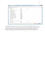
Diagnostics
The Diagnostics window allows you to see the traffic exchanged between the controller and slave
boards. Packets are shown in an annotated form as follows:
22
The DMX512 protocol requires that a NULL Start-Code packet (a standard DMX512 packet) is sent at
least once a second. This can make it difficult to see the contents of the Diagnostics window because
they keep changing, so the Pause / Resume button can be used. The Pause function stops the
window from updating; it has no effect on the DMX512 traffic, which continues to be generated.
23
Software Overview
The remainder of this document will describe the source code used to implement DMX512/RDM and
DALI lighting control. The software for the application consists of three parts
(1) The LightingDemo application itself, running on the PC.
The source code of this application is not provided. Please contact MicroAPL Limited if you
have any queries regarding this software.
The application is written in C# using the .NET application framework. It communicates with
the Controller board via USB using a simple proprietary protocol (not DMX or DALI)
(2) The software running on the Controller board
Full source code of the Controller board application is provided. It is written in C and
compiled with the CodeWarrior for ColdFire tool chain. The free, open-source MQX
operating system is also used, mainly to implement the USB connection.
(3) The software running on the Slave board(s)
Full source code of the Slave board application is provided. It is written in C and compiled
with the CodeWarrior for Microcontrollers tool chain (The microprocessor used on the board
is a Freescale MC13213 processor). No operating system is used.
The software on the Controller and Slave boards can be modified to use only the DMX512/RDM
protocol, or only the DALI protocol, without much difficulty.
Note that some source code files are shared between Controller and Slave implementations. For
example the file dmx_support.c contains support routines used by both boards for DMX512.
Documentation
A very useful source of documentation on the individual routines is the subroutine header in the
source file itself. For example:
24
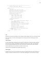
/************************************************************************
*
dmx_controller_init - Allocate and initialise DMX controller
*
*************************************************************************
; Allocates memory for DMX controller device and initialises data structure
;
; Arguments:
;
uint_16
inDeviceNumber
- Physical device to use for I/O
;
uint_8
inUniverseNumber
- DMX Universe Number [1-255]
;
RDM_UID
inUID
- RDM device UID
;
; Result:
;
DMX_HANDLE result
- Handle to DMX device
;
*/
Memory Footprint
The following are approximate figures for the memory footprint of the software on the controller
and slave boards. They should be taken as a guide only. No attempt has been made to reduce the
footprints since they fit comfortably on the target hardware. Contact MicroAPL if memory usage is a
concern.
Controller Board
Code
Data
PC / USB interface
10250
2900
DMX512 code
10050
4300
DALI code
6600
5500
MQX RTOS
63000
1200
Total
89900
13900
Removing the packet-level debugging code makes the application smaller.
Note that the application makes very little use of the MQX RTOS apart from the USB stack, so it
would be possible to run without an RTOS without too much re-coding work.
Slave Board
Code
Data
Application
7800
410
DMX512 code
9500
10
DALI code
6700
50
25
LED control
12800
100
Compiler support libraries
8630
2006 (inc. 2000 byte heap)
Other
230
640
Total
45660
3216
In addition, the slave-board software can be built in a mini-DALI version designed to fit in only 8K of
Flash and 512 bytes of RAM. This version only allows the LED to be controlled using the DALI
protocol. The brightness of the LED can be controlled using the standard DALI command set, but not
the colour of the LED. In addition, the software does not perform thermal monitoring of the LED to
prevent damage by over-heating, leaving it up to hardware to limit the current to a safe maximum
value.
The documentation here will mainly discuss the full slave implementation, not the mini-DALI version,
although most of the source code is shared by the two versions.
DMX512 and RDM implementation on the Controller and Slave Boards
On both controller and slave board, DMX512/RDM data is sent and received using a UART operating
in polled mode.
The DMX512 protocol can be divided into two parts.
In standard DMX512, each slave device has a start address in the range 1 - 512, and a footprint of
one or more ‘slots’. Primary control is achieved by the controller broadcasting NULL Start-Code
packets containing up to 512 slot values.
For added reliability, DMX512 controllers can interleave the NULL Start-Code packets with System
Information Packets (SIPs) which allows a checksum to be appended to the NULL Start-Code data.
The Remote Device Management protocol (RDM) is an extension to standard DMX512. It allows the
controller to send multi-byte messages to an individual slave, and also to get multi-byte replies. In
addition, it allows the controller to discover which devices are connected to the DMX512 network.
The application software on the controller board implements both DMX512 with SIP support, and
RDM. RDM is used to find out which slave devices are connected, ask them for detailed information
about capabilities, and assign DMX512 start addresses.
A DMX512/RDM slave consists of a Root device and optionally one or more sub-devices. The slave
board software implements one sub-device, used to control a single multi-colour LED package. In
principle the software could easily be adapted to support multiple sub-devices, for example multiple
independent white LEDs.
26
The DMX512/RDM implementation on the slave boards supports two RDM personalities:
(a) PERSONALITY_xyY_CONTROL
When configured via RDM to use this personality, the slave board has a footprint of a single DMX512
slot. The controller uses the slot to send a CIE 1931 Y luminance value (0 - 255), and sends the
(x,y) chromaticity values using a separate RDM command.
(b) PERSONALITY_DIRECT_CONTROL
In this personality the slave board has a footprint of up to four DMX512 slots, one for each channel
that the LED supports. For example an LED with three primaries Red, Green and Blue will have a
footprint of three slots. The values in the DMX512 slots are in the range 0-255 and correspond to 0 100% duty cycles.
Note that the controller software doesn’t perform any special handling for RDM responses from a
slave sent with REPONSE_TYPE_ACK_TIMER (meaning that the slave isn’t yet ready to respond).
The Freescale slave-board software never sends this type of response. If required, it can be handled
in application code or by a simple modification to the controller routine rdm_get_response.
Endian Dependencies
DMX512 SIP and RDM packets use big-endian byte ordering for integer values which are more than
one byte wide.
The MCF52259 processor used on the controller board also uses big-endian byte ordering
conventions, as does the CodeWarrior compiler used for the slave board.
However, to make the software as portable as possible all multi-byte accesses are done through
macros:
read_big_endian_u16
read_big_endian_u32
store_big_endian_u16
store_big_endian_u32
For example, the following code reads a 32-bit unsigned value and replaces it with another:
value = read_big_endian_u32 (pointer);
store_big_endian_u32 (pointer, value+1);
27
DALI implementation on the Controller and Slave Boards
On both controller and slave board, DALI data is sent and received using a GPIO port.
Data is sent using a routine which tightly controls the timing of the generated bi-phase signal to
match the DALI specification.
Data is received by using an interrupt service routine which over-samples the signal. The signal has a
frequency of 1200 bits per second but it is bi-phase encoded so there are 2400 phases per second.
The interrupt frequency is 9600 sample per second - i.e. 4 samples per phase. Software compares
the samples to ensure that they match. Because the received signal may vary slightly in frequency or
duty cycle, software considers a match of 3, 4 or 5 samples to be acceptable.
The DALI protocol is really designed for controlling single-colour lights which it calls ‘ballasts’. The
controller can instruct individual ballasts to light up, change to a specified power level, fade up or
down, etc. Ballasts can also be addressed as groups instead of individually, or added to pre-set
scenes. The DALI protocol also includes a means for the controller to discover which DALI slaves are
connected.
DALI commands from controller to slave are two bytes long, and replies from slave to controller are a
single byte (Many commands don’t result in a reply). Each DALI slave has a unique Short Address in
the range 0 - 63.
The DALI implementation used by the controller and slave is standard in all respects except for one
extension: the standard DALI protocol does not include any way for a controller to instruct an LED to
change colour rather than brightness, so a way is needed to achieve this.
In the Freescale implementation, the normal DALI commands affect the brightness of the LED - in CIE
1931 colour space terminology, the power level corresponds to the Y luminance. (In fact, DALI uses a
logarithmic dimming curve, so the value is derived from the log of the luminance).
Since this is the way all DALI devices work, it is possible to use a Freescale DALI controller with nonFreescale DALI slaves, and it means that a Freescale slave looks like a standard ballast to nonFreescale controllers.
In order to convey chromaticity information, the Freescale implementation uses a backdoor route to
extend the command set. The backdoor makes use of a standard DALI command DATA TRANSFER
REGISTER, and is invisible to non-Freescale DALI devices.
Because DALI commands are only two bytes long, all DALI slaves implement a Data Transfer Register
(DTR). In order to program a setting such as the power-on level of a ballast, the DALI controller sends
two 2-byte commands:
; Store 99 in the DTR
DATA TRANSFER REGISTER, 99
; Tell the addressed device to store the DTR as the power-on level
<address>, STORE THE DTR AS POWER ON LEVEL
28
The backdoor command to set chromaticity information relies on the fact that setting the DTR to one
value and then another (without any intervening commands) is both harmless and pointless. No
other DALI controllers are likely to do it, and it has no effect on normal DALI slaves.
In order to send chromaticity information the controller sequences the DTR through a secret multicharacter backdoor key to alert the slave that a chromaticity command is coming. It then uses the DTR
to communicate the (x,y) chromaticity coordinates to the slave. See the routines
dali_send_backdoor_command in the controller and handle_dali_backdoor_command
in the slave for further details.
29
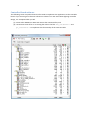
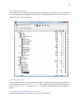
Controller Board software
The following screen snapshot shows the files used to implement the application on the controller
board. If you are using the reference software as a basis for a new stand-alone lighting controller
design, it is anticipated that you will
(a) select either DMX512 or DALI and remove the unwanted files, and
(b) concentrate most effort on re-writing the code in the files usb_interface.c and
pc_interface.c to implement the functionality of the new controller
30
MQX on the controller board
The MQX libraries are derived from the standard MQX 3.3 port to the Freescale M52259EVB
evaluation board, with only one change : The board support package m52259evb.a /
m52259evb_d.a has been re-built to use UART2 instead of UART0 as the standard I/O port. This is
necessary because the Controller board uses UART0 for the DMX512 connection. UART2 is optionally
used for debugging.
To make this change when rebuilding the M52259EVB board support package, edit the file
user_config.h and change as follows:
#define BSPCFG_ENABLE_TTYC
#define BSP_DEFAULT_IO_CHANNEL
1
"ttyc:"
By default, UART2 is configured to use
115200 baud
8 data bits
1 stop bit
No parity
No handshake
Debugging information for the controller board
A number of support routines like debug_printf allow debugging information to be collected.
All calls ultimately call a routine debug_vprintf in the file support.c. This routine is
responsible for outputting the debug text in some form. For example it could send it to the UART2
serial port.
In the current implementation it stores the debug text in a circular buffer, from where the
LightingDemo application on the PC picks it up via a USB request, and UART2 is not used.
C Pre-processor Definitions for the controller board
The Controller board software can be built in a number of configurations:
DMX controller, DALI controller or both
Optional debugging
Code to run on the actual board, or code running in the ‘simulator’ option used by the
LightingDemo application
These build options are controlled by C pre-processor macros.
The following are defined through the CodeWarrior C/C++ Pre-processor Target Settings panel...
31
(a) To enable/disable DMX512/RDM support
#define DMX_CONTROLLER
1
or
#undef DMX_CONTROLLER
(b) To enable/disable DALI support
#define DALI_CONTROLLER
1
or
#undef DALI_CONTROLLER
(c) To specify whether the code runs on actual hardware or in the simulator
#define CONTROLLER_BOARD
1
or
#define SIMULATED_BOARD
1
Additionally, printf-style debugging information can be turned on and off using the
SUPPORT_DEBUGGING equate defined in the header file dali_and_dmx_types.h.
32
Using DMX512/RDM on the Controller Board
This section will discuss how to use the DMX512/RDM controller from application software, looking
at some of the main routines. For a complete example, see the end of the section.
Initialising the DMX_HANDLE
The public interface to the DMX512 software uses an opaque data type DMX_HANDLE. Application
software should begin making a call to dmx_controller_init to allocate a new handle:
Function Prototype:
DMX_HANDLE dmx_controller_init (uint_16 inDeviceNumber,
uint_8 inUniverseNumber,
RDM_UID inUID);
In principle the software could support multiple DMX512 universes if the hardware allowed it.
Initialising the hardware
After the DMX_HANDLE has been initialised, the application should call the routine
dmx_device_init to initialise the hardware interface.
Function Prototype:
DMX_ERROR dmx_device_init (DMX_HANDLE inHandle);
Note that the controller board software to accompany the LightingDemo application allows the user
to switch between DMX512 and DALI protocols dynamically. This is achieved by calling
dmx_device_init/ dmx_device_deinit and the DALI equivalents as appropriate.
RDM Discovery
To perform an RDM discovery process in order to find out which slaves are attached to the DMX512
network, call the rdm_discovery routine
Function Prototype:
DMX_ERROR rdm_discovery (DMX_HANDLE inHandle,
boolval inDoCompleteDiscovery);
This will cause the controller software to initiate RDM discovery, searching the 48-bit RDM address
space for enabled devices. For each slave that is found, the software will request additional
information such as the device manufacturer, number of personalities, footprint, etc.
The result is added to a linked list of all known slaves, in which each item has the following structure.
Note that where a slave implements one or more sub-devices there will be one entry in the linked
list for the Root device, and one for each sub-device.
33
typedef struct DMX_SLAVE_RECORD {
RDM_UID
slave_UID;
uint_16
subDevice;
uint_16
startAddress;
uint_8
uint_8
currentPersonality;
numPersonalities;
uint_8
uint_16
*slotValues;
numSubDevices;
/* Slave UID */
/* RDM_ROOT_DEVICE, or
sub-device number */
/* DMX512 start address */
/* Current personality */
/* Number of personalities
supported */
RDM_PERSONALITY personality [MAX_RDM_PERSONALITIES+1];
/* Personality records.
Note: RDM numbers
personalities from 1 upwards,
so used entries in
this array are in range
1 - numPersonalities */
char
*model;
char
*manufacturer;
uint_16
modelID;
uint_16
numSensors;
struct DMX_SLAVE_RECORD *next;
/* Array of slot values */
/* Number of DMX sub-devices
if RDM_ROOT_DEVICE, else 0 */
/* Model description */
/* Manufacturer description */
/* Model ID */
/* Number of sensors */
/* Linked list of records */
} DMX_SLAVE_RECORD;
The following convenience routines allow you to walk the slave list:
(a) Return count of the number of slave records found.
uint_32 dmx_count_slaves (DMX_HANDLE inHandle);
(b) Return pointer to first slave record, or NULL if no slaves found
DMX_SLAVE_RECORD *dmx_slave_list (DMX_HANDLE inHandle);
(c) Return pointer to Nth slave (starting from 0), or NULL if no such record exists.
DMX_SLAVE_RECORD *dmx_find_nth_slave (DMX_HANDLE inHandle,
int inIndex);
34
Allocation of DMX512 Start Addresses
In order to communicate with a slave through a DMX512 NULL Start-Code packet, the slave needs to
be assigned a DMX512 Start Address.
The routine rdm_allocate_dmx_addresses will use RDM to allocate start addresses to any
slave that doesn’t have one, ensuring that no overlapping start address/footprint values are present.
Function Prototype:
DMX_ERROR rdm_allocate_dmx_addresses (DMX_HANDLE inHandle);
Sending data in DMX512 NULL Start-Code packets
The DMX512 protocol requires that a NULL Start-Code packet is sent at least once a second. It is the
application’s responsibility to call dmx_send_NULL_start_code_packet periodically to
ensure that this requirement is met.
Function Prototype:
DMX_ERROR dmx_send_NULL_start_code_packet (DMX_HANDLE inHandle);
This routine will also cause SIP packets with checksum information to be sent if this option is
enabled.
The slot values that are sent in a NULL Start-Code packet are buffered locally by the controller. To
change one or more slot values, call the dmx_set_slot_values routine.
Function Prototype:
DMX_ERROR dmx_set_slot_values (DMX_HANDLE inHandle,
uint_16 inStartAddress,
uint_16 inNumSlots,
uint_8 *inValues,
boolval inImmediateUpdate);
System Information Packets (SIPs)
The use of SIP packets improves the reliability of DMX512 by adding checksum information, but
slightly reduces the maximum throughput. You can control the generation of SIPs using the
sip_set_checksumming routine. The use of SIPs is recommended in most situations.
Function Prototype:
void sip_set_checksumming (DMX_HANDLE inHandle,
boolval inEnableDisable);
35
Changing the RDM personality of a slave device
As a convenience, the routine rdm_set_personality can be used to change the current personality
used by a slave device. Note that personalities are numbered from 1 upwards in RDM.
Function Prototype:
DMX_ERROR rdm_set_personality (DMX_HANDLE inHandle,
DMX_SLAVE_RECORD *inSlave,
uint_8 inPersonality);
Specifying CIE1931 Colour Space values
The routine rdm_set_chromaticity allows the application to control the chromaticity and
luminance of a slave device. It takes an (x,y) chromaticity coordinate and a Y luminance value as
arguments. The luminance argument is in the range 0.0 to 1.0 to request 0 - 100% of the maximum
lumens that the slave can deliver at the requested chromaticity.
Function Prototype:
DMX_ERROR rdm_set_chromaticity (DMX_HANDLE inHandle,
DMX_SLAVE_RECORD *inSlave,
double in_x,
double in_y,
double in_Y);
Sending other RDM commands
Application software can send other RDM commands to a slave device by using the sequence:
tx_packet = rdm_make_command (inHandle, ...);
errcode = rdm_send_packet (inHandle, tx_packet);
if (errcode == ERR_DMX_OK) {
/* Any response? */
errcode = rdm_get_response (inHandle, tx_packet, &rx_packet, false);
}
Note: It is important that software follows the sequence above. A successful call to
rdm_send_packet will complete with interrupts disabled. The expectation is that it will be
immediately followed by a call to rdm_get_response which re-enables interrupts on completion.
(a) The rdm_make_command routine takes the specified arguments and builds an RDM packet
ready for transmission. The packet is not quite complete at this stage, because checksum
information is not added until rdm_send_packet is called.
36
Function Prototype:
RDM_PACKET *rdm_make_command (DMX_HANDLE inHandle,
RDM_UID inDestination,
uint_16 inSubDevice,
uint_8 inCommandClass,
uint_16 inParameterID,
void *inParameterData,
uint_8 inParameterLength);
The parameters inCommandClass and inParameterID specify the RDM command to send, for
example GET_COMMAND and SLOT_DESCRIPTION
For commands which require additional data, the data is specified through the inParameterData
and inParameterLength parameters. If no additional data is required you can specify NULL and 0.
Example:
slotNumber = 1;
tx_packet = rdm_make_command (dmx_controller,
slave_UID,
subDevice,
GET_COMMAND,
SLOT_DESCRIPTION,
&slotNumber,
2);
The rdm_make_command routine returns a pointer to the RDM packet.
Note that memory for this packet is allocated within the DMX_HANDLE structure. There is no need
for the application to release the memory explicitly - i.e. don’t call free or a similar routine. Equally,
be aware that a new call to rdm_make_command will overwrite any data stored by the previous
call.
(b) The rdm_send_packet routine is used to send an RDM packet over the DMX512 connection.
Function Prototype:
DMX_ERROR rdm_send_packet (DMX_HANDLE inHandle,
RDM_PACKET *inPacket);
(c) The rdm_get_response routine is used to wait for the reply to an RDM command.
Function Prototype:
DMX_ERROR rdm_get_response (DMX_HANDLE inHandle,
RDM_PACKET *inPacketSent,
RDM_PACKET **outPacketReceived,
boolval inAllowNACK);
37
Notice that the second parameter is a pointer to the packet to which a reply is expected. The routine
uses this information to make sure that the reply matches what’s expected in terms of RDM packet
number, reply type, etc.
A pointer to the received packet is returned via the third parameter. This may be NULL on error.
Like rdm_make_command there is no need to free the received packet after it is finished with. The
memory is allocated internally to the DMX controller and will be reused for the next received packet.
Example Code
The following code shows a more complete example using the DMX controller software. It includes
the following steps:
Initialise the controller
Perform an RDM discovery process
Send an RDM packet to ask the first slave for its software version string
Send a NULL Start-Code packet
For clarity some error checking has been omitted.
#include "dmx.h"
#include "dmx_controller.h"
#include "dmx_support.h"
void dmx_demonstration (void)
{
DMX_HANDLE
dmx_controller;
RDM_UID
UID;
DMX_ERROR
errcode;
DMX_SLAVE_RECORD
*slave;
int
attempt;
RDM_PACKET
*tx_packet, *rx_packet;
uint_8
slot_values [1];
/* Initialise controller */
UID.manufacturerID = FREESCALE_ESTA_MANUFACTURER_ID;
UID.deviceID = 0x10000000;
dmx_controller = dmx_controller_init (0, 1, UID);
if (dmx_controller == NULL)
return;
/* Initialise controller hardware */
dmx_device_init (dmx_controller);
38
#ifdef SUPPORT_DEBUGGING
/* Set debugging level */
dmx_set_debug_level (dmx_controller, DEBUG_PACKETS);
#endif
/* Say we want to use checksumming of NULL Start-Code packets
for extra reliability */
sip_set_checksumming (dmx_controller, true);
/* Perform RDM discovery process to find out which slaves
are present */
rdm_discovery (dmx_controller, true);
/* Allocate DMX512 start addresses to any slaves without one */
rdm_allocate_dmx_addresses (dmx_controller);
/* Ask the first slave what its software version is... */
slave = dmx_find_nth_slave (dmx_controller, 0);
if (slave == NULL)
return;
for (attempt = 0; attempt < 3; attempt++) {
/* Make the GET SOFTWARE_VERSION_LABEL command */
tx_packet = rdm_make_command (dmx_controller,
slave->slave_UID,
slave->subDevice,
GET_COMMAND,
SOFTWARE_VERSION_LABEL, NULL,
0);
/* Send it */
errcode = rdm_send_packet (dmx_controller, tx_packet);
if (errcode != ERR_DMX_OK)
continue;
/* Any response? */
errcode = rdm_get_response (dmx_controller,
tx_packet,
&rx_packet,
false);
if (errcode == ERR_DMX_OK) {
// ... Do something with the software version string here...
break;
}
}
39
/* Send DMX512 NULL Start-Code packet */
slot_values [0] = 99;
dmx_set_slot_values (dmx_controller,
slave->startAddress,
1,
slot_values, true);
}
40
Using DALI on the Controller Board
This section will discuss how to use the DALI controller from application software, looking at some of
the main routines. For a complete example, see the end of the section.
Initialising the DALI_HANDLE
The public interface to the DALI software uses an opaque data type DALI_HANDLE. Application
software should begin making a call to dali_controller_init to allocate a new handle:
Function Prototype:
DALI_HANDLE dali_controller_init (uint_16 inDeviceNumber);
In principle the software could support multiple DALI connections if the hardware allowed it.
Initialising the hardware
After the DALI_HANDLE has been initialised, the application should call the routine
dali_device_init to initialise the hardware interface.
Function Prototype:
DALI_ERROR dali_device_init (DALI_HANDLE inHandle);
Note that the controller board software to accompany the LightingDemo application allows the user
to switch between DALI and DMX512 protocols dynamically. This is achieved by calling
dali_device_init/ dali_device_deinit and the DMX512 equivalents as appropriate.
DALI Discovery
To perform an DALI discovery process in order to find out which slaves are attached to the DALI
network, call the dali_discovery routine
Function Prototype:
DALI_ERROR dali_discovery (DALI_HANDLE inHandle);
This will cause the controller software to initiate DALI discovery, searching the 24-bit DALI ‘randomaddress’ address space for enabled devices. For each slave that is found, the software will request
additional information such as the type of LED and whether the device already has a DALI Short
Address.
The result is added to a linked list of all known slaves, in which each item has the following structure.
41
typedef struct DALI_SLAVE_RECORD {
uint_8
shortAddress;
uint_32
randomAddress;
uint_8
modelID;
struct DALI_SLAVE_RECORD *next;
/* DALI short address */
/* DALI random address at which
slave responded */
/* Type code uniquely
identifying LED type */
/* Linked list of records */
} DALI_SLAVE_RECORD;
The following convenience routines allow you to walk the slave list:
(d) Return count of the number of slave records found.
uint_32 dali_count_slaves (DALI_HANDLE inHandle);
(e) Return pointer to first slave record, or NULL if no slaves found
DALI_SLAVE_RECORD *dali_slave_list (DALI_HANDLE inHandle);
(f) Return pointer to Nth slave (starting from 0), or NULL if no such record exists.
DALI_SLAVE_RECORD *dali_find_nth_slave (DALI_HANDLE inHandle,
int inIndex);
During the DALI discovery process the controller will also allocate a DALI Short Address (0 - 63) to any
slave which does not have one.
Specifying CIE1931 Colour Space values
The routine dali_set_chromaticity allows the application to control the chromaticity and
luminance of a slave device. It takes an (x,y) chromaticity coordinate and a Y luminance value as
arguments. The luminance argument is in the range 0.0 to 1.0 to request 0 - 100% of the maximum
lumens that the slave can deliver at the requested chromaticity.
Function Prototype:
DALI_ERROR dali_set_chromaticity (DALI_HANDLE inHandle,
DALI_SLAVE_RECORD *inSlave,
double in_x,
double in_y,
double in_Y);
Sending other DALI commands
The set of commands defined by the DALI protocol can be divided into four categories:
42
Direct commands instructing the ballast to switch to a specified power level 0-255
Normal DALI commands for which a response is not expected - e.g. OFF, STEP UP
Query commands for which a response is expected, e.g. QUERY STATUS
Special commands sent to all devices, e.g. PROGRAM SHORT ADDRESS (only the ballast
which has been previously selected responds)
(a) For the first three categories the two-byte DALI command format is:
YAAAAAAS XXXXXXXX
where:
S = 0 : Direct power level
S = 1 : DALI command
If the command is sent to an individual ballast, Y = 0 and AAAAAA = ballast short address (0 - 63)
If the command is sent to a group of ballasts, Y = 1 and 00AAAA = group address (0 - 15)
To send these commands, application software can use dali_send_normal_command:
Function Prototype:
DALI_ERROR dali_send_normal_command (DALI_HANDLE inHandle,
uint_8 inAddress,
uint_8 inCommand);
For example, to send a direct power level command to the individual ballast with short address 5:
addressByte = (5 << 1);
dali_send_normal_command (dali_controller, addressByte, 100);
To send the command OFF to the same ballast:
addressByte = (5 << 1) | 1;
dali_send_normal_command (dali_controller, addressByte, DALI_OFF);
(b) If a response from the DALI slave is expected the application should immediately follow this up
with a call to dali_wait_response:
Function Prototype:
DALI_ERROR dali_wait_response (DALI_HANDLE inHandle,
uint_16 *outResponse);
Note that DALI responses are only ever 8 bits, but for certain DALI commands the slave sends no
response at all if the answer to a query is ‘no’. In order to accommodate this, the
43
dali_wait_response returns a 16-bit response value where RESPONSE_NO (value 0x100)
indicates that no response was received.
(c) DALI special commands can be sent using the following subroutine:
Function Prototype:
DALI_ERROR dali_send_special_command (DALI_HANDLE inHandle,
uint_8 inCommand,
uint_8 inByte2);
The following example sends the DATA TRANSFER REGISTER command to all devices instructing
them to load the DTR register with the value 100:
dali_send_special_command (dali_controller,
DALI_SC_DATA_TRANSFER_REGISTER,
100);
Example Code
The following code shows a more complete example using the DALI controller software. It includes
the following steps:
Initialise the controller
Perform an DALI discovery process
Send a DALI packet to ask the first slave for its device type
Send direct power control instruction to the first slave
For clarity some error checking has been omitted.
44
#include "dali.h"
#include "dali_controller.h"
#include "dali_support.h"
void dali_demonstration
{
DALI_HANDLE
DALI_ERROR
DALI_SLAVE_RECORD
int
uint_8
uint_16
(void)
dali_controller;
errcode;
*slave;
attempt;
addressByte;
response;
/* Initialise controller */
dali_controller = dali_controller_init (0);
if (dali_controller == NULL)
return;
/* Initialise controller hardware */
dali_device_init (dali_controller);
#ifdef SUPPORT_DEBUGGING
/* Set debugging level */
dali_set_debug_level (dali_controller, DEBUG_PACKETS);
#endif
/* Perform DALI discovery process to find out which slaves
are present */
dali_discovery (dali_controller);
/* Ask the first slave what its device type is... */
slave = dali_find_nth_slave (dali_controller, 0);
if (slave == NULL)
return;
for (attempt = 0; attempt < 3; attempt++) {
/* Send QUERY DEVICE TYPE command */
addressByte = (uint_8) (((slave->shortAddress) << 1) | 1);
errcode = dali_send_normal_command (dali_controller,
addressByte,
DALI_QUERY_DEVICE_TYPE);
if (errcode != ERR_DALI_OK)
continue;
/* Any response? */
errcode = dali_wait_response (dali_controller, &response);
if (errcode == ERR_DALI_OK) {
//... Do something with the device type information here...
break;
}
}
45
/* Send direct power instruction to first slave */
addressByte = (uint_8) ((slave->shortAddress) << 1);
errcode = dali_send_normal_command (dali_controller, addressByte, 100);
}
46
Slave Board Software
The following screen snapshot shows the files used to implement the application on the slave board.
If you are building a product based on this software you will probably want to remove either the
DMX512 or DALI code as appropriate.
The ansifs.lib Library
The application makes use of floating point data types to calculate colour balancing parameters and
hence requires the support of the ansifs.lib library which incorporates software floating point
routines. In the ansifs.lib library, the double data type is represented in the 4-byte IEEE754
format.
C Pre-processor Definitions for the slave board
The Slave board software can be built in a number of configurations:
47
DMX512 slave, DALI slave or both
A mini-DALI version which occupies only 8K of Flash and 512 bytes of RAM
Code to run on the actual board, or code running in the ‘simulator’ option used by the
LightingDemo application
These build options are controlled by C pre-processor macros.
The following are defined through the CodeWarrior Compiler for HC08 Target Settings panel...
(a) To enable/disable DMX512/RDM support
#define DMX_SLAVE
1
or
#undef DMX_SLAVE
(b) To enable/disable DALI support
#define DALI_SLAVE
1
or
#undef DALI_SLAVE
(c) To enable the mini-DALI version
#define MINI_DALI 1
(d) To specify whether the code runs on actual hardware or in the simulator
#define SLAVE_BOARD
1
or
#define SIMULATED_BOARD
1
Mini-DALI version of the slave software
The slave software can also be built in a mini-DALI version which has a very small memory footprint:
8K of Flash and 512 bytes of RAM for the complete application.
This version allows a monochrome LED to be controlled using DALI commands. Compared to the full
slave software it lacks the following features:
Colour control
Thermal regulation
Control via the DMX512 / RDM protocol instead of DALI
XML description of LED characteristics
All of the source files used by the mini-DALI version are the same ones used for the full version with
the exception of two files:
main.c
is replaced by
mini_dali_main.c
48
led_hcs08.c
is replaced by
mini_dali_hcs08.c
A separate CodeWarrior project is provided for building the mini-DALI version.
LED Control
A typical LED package consists of three or four separately controllable colours, e.g. Red, Green, Blue
and White.
Each colour, or channel, is controlled by a separate power stage on the slave board. The ‘fully-on’
current and voltage used by the LED channel are determined by hardware on the board (including
current-limiting resistors to prevent LED damage). Colour control is achieved by using a PWM signal
to control the channel current, varying the duty cycle in order to vary the brightness of the LED.
The topic of colour balancing is discussed in more detail below.
XML Descriptions of LED Types
In order to perform colour balancing and thermal regulation, the slave board software needs to
know the characteristics of each LED package. This information is stored in an easy-to-maintain XML
format, stored in Flash on the slave.
The same XML description is also used by the LightingDemo application on the PC for two purposes...
When using the DMX512 RDM protocol, the controller board is able to interrogate the
slave in order to determine the LED name, manufacturer, number of primaries, etc. This
information is passed on to the LightingDemo application running on the PC.
However, this is not possible in DALI because the DALI protocol only supports single byte
responses from slave to controller. For DALI only, the LightingDemo application reads the
information directly from its own copy of the XML file.
When simulating a controller board and slave boards in software on the PC, the XML file is
used to determine the LED characteristics.
A typical XML description of an LED is as follows:
49
<!--============================================
Luminus PhlatLight CBM-380
==============================================-->
<led>
<id>2</id>
<name>PhlatLight CBM-380</name>
<manufacturer>Luminus</manufacturer>
<max_current>32.0</max_current>
<board_type>1</board_type>
<temperature_matrix>
0.635 0.156 0.158 0.091
0.169 0.595 0.103 0.126
0.158 0.094 1.113 0.158
0.116 0.130 0.183 0.742
</temperature_matrix>
<channel>
<!-Red: Luminus PhlatLight CBM-380 -->
<color>Red</color>
<pwm_channel>1</pwm_channel>
<forward_current>12.0</forward_current>
<forward_voltage>2.3</forward_voltage>
<flux>700.0</flux>
<cie1931_x>0.701</cie1931_x>
<cie1931_y>0.299</cie1931_y>
<max_temperature>80</max_temperature>
</channel>
... other channels follow
</led>
<id>
Software on the slave board reads the two hardware switches labelled 10’s and 1’s to obtain an LED
type in the range 1 - 99. This is matched against the <id> tag to determine which type of LED is
connected.
<max_current>
For some LED packages, driving all the LED channels at 100% duty cycle will exceed the maximum
rated current for the LED, even though the individual channels are all in range. For example the
Luminus PhlatLight CBM-380 allows 12A, 12A, 8.1A and 9A for the Red, Green, Blue and White
channels individually, but only allows a maximum of 32A in total.
A value of 0 can be specified if this problem does not exist.
<board_type>
Possible values are 0 for the low-power board and 1 for the high-power board. This information is
used by the software to determine how to control the Enable signals to the board’s drive stages.
50
<temperature_matrix>
This matrix is used in temperature calculations. See the section “Temperature Regulation” for more
details.
<channel>
The channel tag should be repeated once for each independently controlled LED primary in the
package. The channels should be listed in the same order as they will occur in the DMX512 footprint.
<pwm_channel>
Specifies which of the PWM channels is used to control this device. Possible values are 1 - 4 for
TPM2CH1 - TPM2CH4. This information is used in the routine led_update_power_levels.
<forward_current>
Specifies the forward current (in Amps) which the LED channel uses at 100% PWM duty cycle.
<forward_voltage>
Specifies the forward voltage (in Volts) corresponding to the forward current value. The software
uses these two values to calculate power dissipation at 100% PWM duty cycle in order to perform
thermal regulation.
<flux>
Specifies the luminous flux (in Lumens) produced at 100% PWM duty cycle. This information is used
for colour balancing.
<cie1931_x> and <cie1931_y>
Specify the (x,y) chromaticity coordinates of the LED. Both values are in the range 0.0 - 1.0. This
information is used for colour balancing.
<max_temperature>
Specifies the maximum junction temperature for the LED channel. See the section “Temperature
Regulation” for more details.
Regenerating the XML File
The XML descriptions are held in a source file led_descriptions.xml which needs to be stored
in Flash on the slave board.
Unfortunately, the standard version of CodeWarrior for the slave board cannot include an arbitrary
binary file (you need to buy a ‘bean’ to let you do this), so some way is needed of including the XML
descriptions in the build.
The solution used here is to use a separate utility to convert the XML file into an assembler source
file led_descriptions.asm containing ASCII strings, e.g.
51
dc.b
dc.b
dc.b
"
"
"
<id>1</id>"
<name>Luxeon Rebel RGB + CW</name>"
<manufacturer>Philips Lumileds</manufacturer>"
The utility is a small .exe program that runs at the Windows command prompt.
make_xml_asm
<XML file> <assembler file>
Full source code of the utility is included in the xml_utility folder.
Colour Balancing
Colour balancing is performed by the routine led_convert_xy_to_levels.
The CIE 1931 Colour Space chromaticity coordinate (x,y)and luminance value Y are related to the
equivalent XYZ tristimulus values by the following equations:
x = Y / (X + Y + Z)
y = Y / (X + Y + Z)
Or, re-arranging:
X = (Y / y ) x
Z = (Y / y) (1 - x - y)
The routine begins by computing the XYZ tristimulus values of the target colour.
Using the information from the XML description of the LED, the software can also calculate the
tristimulus values of the individual primaries like Red.
The next step is to consider the simplified case of a package with only three primaries - e.g. consider
Red, Green and Blue, and ignore any White channel. The software needs to calculate the duty cycles
(in the range 0.0 - 1.0 for 0-100%) needed for each channel in order to achieve the target
chromaticity at maximum brightness.
The XYZ value of the target colour and the duty cycles are related by a matrix multiplication:
X
Y
Z
Duty Cycle Red
= M x
Duty Cycle Green
Duty Cycle Blue
Software needs to determine the 3 x 3 matrix M and then compute the inverse of M in order to
calculate the duty cycles required.
M can be determined from the XYZ tristimulus values of the primaries. For example when only the
Red primary is illuminated using 100% duty cycle, it produces the lumens and (x,y) chromaticity
52
specified in the XML description. For the Luminus PhlatLight CBM380 example given earlier these are
Y = 700 lumens and (x,y) = (0.701, 0.299).
Converting these to XYZ we have:
Xred
Yred
1
= M x
Zred
0
0
It follows that the entire matrix M is simply:
Xred
Xgreen Xblue
Yred
Ygreen Yblue
Zred
Zgreen Zblue
Having calculated the required duty cycles, one or more values may turn out to be negative. This
happens when the target colour is outside the triangular gamut of all possible colours that can be
produced by mixing the three LED primaries. In this case the colour is adjusted so that it is in-gamut
by adding just enough to bring the colour to the edge of the triangle.
The discussion above considered the simplified case of only three primaries. Many LED packages
have four primaries - e.g. Red, Green, Blue and White. Effectively this means that matrix M has three
rows but has four columns - i.e. it is 3 x 4 instead of 3 x 3, meaning that there is no unique solution to
the colour-balancing problem.
The software on the slave board considers the four primaries in groups of three-at-at-time, e.g.
Red/Green/Blue, Red/Green/White, Red/Blue/White and Green/Blue/White. The target colour can
normally be represented by either of two of these combinations, so the software chooses a solution
that will deliver maximum brightness.
Adjusting Duty Cycles
The routine led_convert_xy_to_levels discussed above will calculate the duty cycles
necessary to achieve the target colour at maximum brightness. These duty cycles may need to be
scaled back:
(a) Because the application software requested a luminance value of less than 100%
(b) Because driving the LED package with the calculated duty cycles would exceed its maximum
rated current
(c) Because driving the LED package with the calculated duty cycles would cause it to overheat.
53
Adjustment takes place in the routine led_update_power_levels, which is also responsible
for programming the PWM module and controlling the Enable signals to the LED power stages.
Temperature Regulation
Driving too much current through an LED for too long can cause it to overheat, shortening the
working life of the LED or even damaging it. In order to avoid this it is necessary to monitor the
temperature and reduce the power if necessary.
Each channel of a multi-colour LED package will have a maximum recommended junction
temperature. For example the PhlatLight CBM-380 maximum junction temperature for Red is 80°C.
These values are specified by the <max_temperature> tags in the XML file.
The junction temperatures of an LED package cannot be measured directly. Instead they must be
calculated by measuring an accessible temperature (e.g. the heat sink temperature) using a
thermistor, and then calculating the junction temperatures using the power dissipation for each
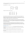
channel and a 4x4 matrix PM.
Power Red
TJunction Red
Power Green
TJunction Green
= Tthermistor + PM x
TJunction Blue
Power Blue
TJunction White
Power White
The PM matrix is the power-to-temperature matrix as recommended by the LED manufacturer and
read from <temperature_matrix> tag in the XML file. For example, for the Luminus PhlatLight
CBM-380 the matrix is:
0.635
0.169
0.158
0.116
0.156
0.595
0.094
0.130
0.158
0.103
1.113
0.183
0.091
0.126
0.158
0.742
The matrix contains thermal resistance values. Note that the temperature of each LED junction does
not just depend on the heat sink temperature and its own thermal resistance - there is cross-talk
between the channels. For example if the Green LED is being driven, it causes the Red LED junction
to heat up.
The Power figure for each LED is calculated as follows:
Power = Forward Voltage x Forward Current x Duty Cycle
54
Because the Forward Voltage and Forward Current are fixed by hardware it is not necessary to do
the complete multiplication every time. Instead they can be used to compute a new version of the
PM matrix PM’ so that the junction temperatures can be calculated by the following equation:
TJunction Red
Duty Cycle Red
TJunction Green
Duty Cycle Green
= Tthermistor + PM’ x
TJunction Blue
Duty Cycle Blue
TJunction White
Duty Cycle White