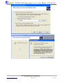
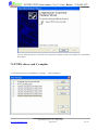
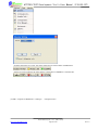
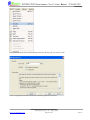
1
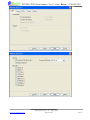
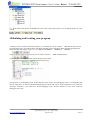
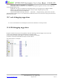
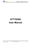
ATT7025/7027 Development Tool’s User Manual(210-SD-127)
ATT7025/7027
Development Tool’s
User Manual
版权归钜泉光电科技(上海)有限公司所有
http://www.hitrendtech.com
Page1 of 20
Rev1.0
ATT7025/7027 Development Tool’s User Manual(210-SD-127)
Version history
Version Update
Remark
V0.1
2008-01-17 First draft
V1.0
2008-01-21 Release
Tel:
021-51035886
Fax: 021-50277833
Email: [email protected]
Web: http://www.hitrendtech.com
版权归钜泉光电科技(上海)有限公司所有
http://www.hitrendtech.com
Page2 of 20
Rev1.0
ATT7025/7027 Development Tool’s User Manual(210-SD-127)
Directory
1 Introduction.............................................................................................................................................................4
2 Features...................................................................................................................................................................4
3 Software and Related documentations....................................................................................................................4
4 Overview.................................................................................................................................................................4
5 USB-Serial Port Device ..........................................................................................................................................5
6 Software Installation ...............................................................................................................................................5
7ATT702x driver and C compiler ..............................................................................................................................8
8Creating a new project ...........................................................................................................................................11
9 Creating a new file................................................................................................................................................14
10 Building and Loading your program...................................................................................................................18
11Debugging Suggestions........................................................................................................................................19
12 C code debugging suggestions............................................................................................................................20
13 ASM debugging suggestions...............................................................................................................................20
版权归钜泉光电科技(上海)有限公司所有
http://www.hitrendtech.com
Page3 of 20
Rev1.0
ATT7025/7027 Development Tool’s User Manual(210-SD-127)
1 Introduction
MedWin is an Integrated Development Environment that combines project management, source code editing,
and program debugging in one single, powerful environment. It provides a most convenient way for debugging
the ATT702X products. This user manual explains the steps needed to use MedWin.
2 Features
Two breakpoints
Communication through USB-Serial Port device
Connect an extern power supply to ATT702X
3 Software and Related documentations
MedWinV3 software
ATT702X driver
USB to Serial driver
Medwin_manual. pdf
ATT702x development tool’s user manual (downloaded from the ATT702x web site at www.hitrendtech.com )
4 Overview
版权归钜泉光电科技(上海)有限公司所有
http://www.hitrendtech.com
Page4 of 20
Rev1.0
ATT7025/7027 Development Tool’s User Manual(210-SD-127)
5 USB-Serial Port Device
The red line represents pin 1, all the pins are configured as the chart below:
1 RX0
VCC
2
3 GND
/RST
4
5 TX0
TMS1
6
7 Undefined Undefined 8
9 Undefined Undefined 10
The switch should be turned to right, in other words the narrower side.
6 Software Installation
The file “MedwinV3 software and related documentations . rar” includes 3 folders described
as below:
1) the installation file of MedWinV3
2) ATT702x Driver
3) USB-Serial Driver
版权归钜泉光电科技(上海)有限公司所有
http://www.hitrendtech.com
Page5 of 20
Rev1.0
ATT7025/7027 Development Tool’s User Manual(210-SD-127)
To install the MedWinV3 software for ATT702x:
(1)Double click “setup.exe” in “MedWinV3” folder. The setup program guides you through installation process.
Follow the setup instructions on the screen. On completion of the setup program execution, the MedWinV3.0
program icons are created in the selected folder.
(2) Please copy all the files in “ATT702X_Driver” folder to the selected folder in process one (the folder user
select to install MedWinV3).
(3) To install USB-Serial driver:
a) Connect the USB-Serial Port device to PC, there will be a “Found New Hardware” dialog on the
screen, please select “ No, not this time ”
b)Follow the wizard to finish the installation process:
版权归钜泉光电科技(上海)有限公司所有
http://www.hitrendtech.com
Page6 of 20
Rev1.0
ATT7025/7027 Development Tool’s User Manual(210-SD-127)
版权归钜泉光电科技(上海)有限公司所有
http://www.hitrendtech.com
Page7 of 20
Rev1.0
ATT7025/7027 Development Tool’s User Manual(210-SD-127)
c)If you install this driver at the first time, maybe the operation system will remind you to install the
driver again.
7ATT702x driver and C compiler
(1) Add ATT702x driver to MedWinV3: “Settings”
“Driver Manager”
版权归钜泉光电科技(上海)有限公司所有
http://www.hitrendtech.com
Page8 of 20
Rev1.0
ATT7025/7027 Development Tool’s User Manual(210-SD-127)
Please select “ChipICE ATT702X Emulator Driver” and click the button “OK”.
According to the crystal on target board, user should select the clock of development tool.
版权归钜泉光电科技(上海)有限公司所有
http://www.hitrendtech.com
Page9 of 20
Rev1.0
ATT7025/7027 Development Tool’s User Manual(210-SD-127)
If all the operations are correct, the status will be shown at the bottom of MedWinV3:
If there are some problems, the status shown at the bottom of MedWinV3 will like this:
(2)Add C compiler to MedWinV3: “Settings”
“Compiler Tools”
版权归钜泉光电科技(上海)有限公司所有
http://www.hitrendtech.com
Page10 of 20
Rev1.0
ATT7025/7027 Development Tool’s User Manual(210-SD-127)
If user select Keil company ’s compiler, you should set path to folder that Keil was installed before. ( You
must ensure that you have installed Keil software in your PC )
8Creating a new project
(1) Launch MedWinV3
(2) “Project” “New Project” , please select driver “ChipICE ATT702x Emulator Driver”
版权归钜泉光电科技(上海)有限公司所有
http://www.hitrendtech.com
Page11 of 20
Rev1.0
ATT7025/7027 Development Tool’s User Manual(210-SD-127)
(3) In the project Name field, type the project name. In the location field, type or browse to the folder you created.
版权归钜泉光电科技(上海)有限公司所有
http://www.hitrendtech.com
Page12 of 20
Rev1.0
ATT7025/7027 Development Tool’s User Manual(210-SD-127)
(4) Recommended Optimizations setting is “<default>”
(5) You can add the source files, library files or head files that have been created before in this dialog.
If you don’t want to add any file, please click Next.
版权归钜泉光电科技(上海)有限公司所有
http://www.hitrendtech.com
Page13 of 20
Rev1.0
ATT7025/7027 Development Tool’s User Manual(210-SD-127)
(6) Click Finish. MedWinV3 creates a project file.
9 Creating a new file
(1) “Project” “New File”
版权归钜泉光电科技(上海)有限公司所有
http://www.hitrendtech.com
Page14 of 20
Rev1.0
ATT7025/7027 Development Tool’s User Manual(210-SD-127)
(2)Type the file name in the file name field and choose the file type you want to create.
(3)If a C language file will be created, the wizard will guide user as below:
版权归钜泉光电科技(上海)有限公司所有
http://www.hitrendtech.com
Page15 of 20
Rev1.0
ATT7025/7027 Development Tool’s User Manual(210-SD-127)
版权归钜泉光电科技(上海)有限公司所有
http://www.hitrendtech.com
Page16 of 20
Rev1.0
ATT7025/7027 Development Tool’s User Manual(210-SD-127)
(4) Click finish and you will see the new file in Files Manager.
版权归钜泉光电科技(上海)有限公司所有
http://www.hitrendtech.com
Page17 of 20
Rev1.0
ATT7025/7027 Development Tool’s User Manual(210-SD-127)
(5) If the status at the bottom of MedWinV3 is the same as the picture below, user can debug the file he or she
created.
10 Building and Loading your program
(1)When you have created a functional program, you can build it. Use the “Project” “Rebuild all” the first time
you build the project. An output window will show the build process and status. When the build is finished, the
output window will display “<Compiler> C51 COMPILATION COMPLETE. 0 WARNING(S), 0 ERROR(S)”
(2)If you want to debug your program, you can use the “Project”
“Make and Download”.
(3)The program in debugging mode will be like the picture below:
(4)If program is in debugging mode, the development tools inserts some debugging codes to corresponding hex
files in output files. If user has finished debugging the program and want to create original hex file, please use
“Settings” “Emulator”. The check box “Insert debugging code” decides whether to insert some codes for
debugging to hex file.
版权归钜泉光电科技(上海)有限公司所有
http://www.hitrendtech.com
Page18 of 20
Rev1.0
ATT7025/7027 Development Tool’s User Manual(210-SD-127)
(5)You can download your program to target board directly by using “memory”
“Download”.
11Debugging Suggestions
(1)There are some restrictions when user is debugging the program.
1)Serial Port 0 and Time 2 can’t be configured. User can’t disable EA and Serial Port 0 interrupt.
Watch Dog needs to be disabled.
版权归钜泉光电科技(上海)有限公司所有
http://www.hitrendtech.com
Page19 of 20
Rev1.0
ATT7025/7027 Development Tool’s User Manual(210-SD-127)
2)The system must be 5.5296MHz or 11.0592MHz.
3)The SFR window in MedWinV3 can’t display written-protect registers correctly. User can get real
values through indirect ways.
4)32K flash can only be configured as code flash and user can’t program from 7C00H to 8000H.
5)When user is debugging the program, MCU always execute at high frequency mode.
6)Two breakpoints can’t be set adjacently.
7)If user has finished executing “memory” “download” “Program/Verify”, please don’t close the
“Program flash” window at once. You should remove USB-Serial Port at first otherwise the program download
before will be erased.
12 C code debugging suggestions
It is not recommended to set the breakpoint at the end of subroutine or interrupt routine.
13 ASM debugging suggestions
Program execution may stop on wrong address when the following situations happen at the same time.
(1)User sets breakpoints at the end of subroutine or interrupt routine.
(2)The instruction under break address is the entrance address of a function.
(3)The PC is under the break address and user execute “RUN”.
The picture below is a example:
版权归钜泉光电科技(上海)有限公司所有
http://www.hitrendtech.com
Page20 of 20
Rev1.0