1
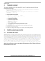
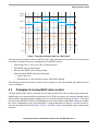
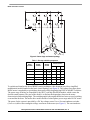
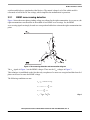
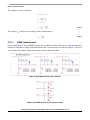
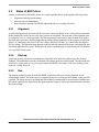
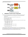
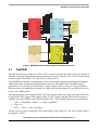
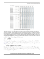
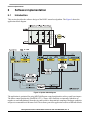
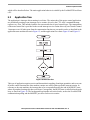
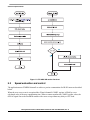
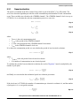
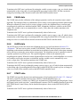
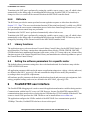
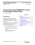
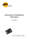
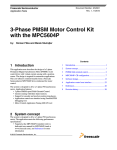
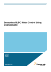
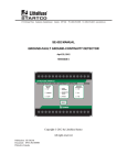
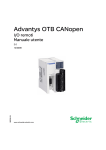
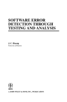
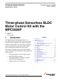
Freescale Semiconductor Application Note Document Number: AN4268 Rev. 0, 02/2011 Three-phase Sensorless BLDC Motor Control Kit with the MPC5604P by: Petr Konvicny Rožnov Czech Republic 1 Introduction This application note describes the design of a three-phase brushless DC (BLDC) motor control drive using a sensorless algorithm. The design is targeted at automotive applications. This cost-effective solution is based on the Freescale Semiconductor MPC5604P device, dedicated for automotive motor control. The system is designed to drive a three-phase BLDC motor without a positional feedback sensor. Application features include: • Three-phase BLDC sensorless speed control • Back-EMF (BEMF) sensing • Application control user interface using the FreeMASTER debugging tool • Maximal motor current limitation © Freescale Semiconductor, Inc., 2011. All rights reserved. Contents 1 2 3 4 5 6 7 Introduction . . . . . . . . . . . . . . . . . . . . . . . . . . . . . . . . . . . 1 System concept . . . . . . . . . . . . . . . . . . . . . . . . . . . . . . . . 2 BLDC sensorless control . . . . . . . . . . . . . . . . . . . . . . . . . 2 3.1 Brushless DC motor . . . . . . . . . . . . . . . . . . . . . . . . 2 3.2 Principles of six-step BLDC motor control . . . . . . . . 3 3.3 States of BLDC drive . . . . . . . . . . . . . . . . . . . . . . . . 7 MPC5604P controller board configuration. . . . . . . . . . . . 8 4.1 FlexPWM . . . . . . . . . . . . . . . . . . . . . . . . . . . . . . . . . 9 4.2 CTU . . . . . . . . . . . . . . . . . . . . . . . . . . . . . . . . . . . . 10 4.3 eTIMER . . . . . . . . . . . . . . . . . . . . . . . . . . . . . . . . . 11 Software implementation . . . . . . . . . . . . . . . . . . . . . . . . 12 5.1 Introduction . . . . . . . . . . . . . . . . . . . . . . . . . . . . . . 12 5.2 Application flow . . . . . . . . . . . . . . . . . . . . . . . . . . . 13 5.3 Speed evaluation and control . . . . . . . . . . . . . . . . 14 5.4 Zero-cross detection . . . . . . . . . . . . . . . . . . . . . . . 16 5.5 Current limitation controller . . . . . . . . . . . . . . . . . . 16 5.6 State machine . . . . . . . . . . . . . . . . . . . . . . . . . . . . 16 5.7 Library functions . . . . . . . . . . . . . . . . . . . . . . . . . . 20 5.8 Setting the software parameters for a specific motor 20 FreeMASTER user interface . . . . . . . . . . . . . . . . . . . . . 20 6.1 Application start . . . . . . . . . . . . . . . . . . . . . . . . . . . 21 Conclusion. . . . . . . . . . . . . . . . . . . . . . . . . . . . . . . . . . . 21 System concept 2 System concept The system is designed to drive a three-phase BLDC motor. The application meets the following performance specifications: • Targeted at the MPC5604P microcontroller (refer to the dedicated reference manual for the MPC5604P, found at www.freescale.com) • Running on the MPC5604P control drive board (refer to the dedicated user manual for the MPC5604P controller board) • Control technique incorporating: — Sensorless control of a three-phase BLDC motor — Zero-crossing technique — Closed-loop speed control — Closed-loop current control — Starting up with alignment — BEMF voltage sensing — 50 µs sampling period with the FreeMASTER recorder • FreeMASTER software control interface (motor start/stop, speed set-up) • FreeMASTER software monitor • DC bus over-voltage, under-voltage, over-current, and overload protection 3 BLDC sensorless control 3.1 Brushless DC motor The BLDC motor is a rotating electric machine with a classic three-phase stator. As in an induction motor, the rotor has surface-mounted permanent magnets. There are no brushes on the rotor and the commutation is performed electronically at a certain rotor position. The displacement of the magnets on the rotor creates a trapezoidal BEMF shape, which means that a DC voltage with a rectangular shape (see Figure 1) can be used to create a rotational field with low torque ripples. The motor can have more than one pole pair per phase. The pole pair per phase defines the ratio between the electrical revolution and the mechanical revolution. The rectangular shape of the applied voltage ensures the simplicity of control and drive. However, the rotor position must be known at certain angles in order to align the applied voltage with the BEMF. The best efficiency is achieved when BEMF and commutation events are aligned, in which case the motor behaves as a DC motor. Three-phase Sensorless BLDC Motor Control Kit with the MPC5604P, Rev. 0 2 Freescale Semiconductor BLDC sensorless control Voltage Phase A Phase B Phase C ef A ef B ef C Electrical angle 30° sector 1 60° 90° 2 120° 150° 3 180° 210° 4 240° 270° 5 300° 330° 0° 6 Figure 1. Three-phase voltage system for a BLDC motor The main task for sensorless control of a BLDC motor is the estimation of rotor position. For rotor position estimation, this application uses a technique based on BEMF sensing. • Speed range from 5–10% up to 100% of nominal speed • The BEMF must be high enough • Based on the BEMF zero-crossing method • Other advanced BEMF estimation techniques: — System observers — Measurement of a non-conductive phase with multi-sampling The following sections discuss the concept of zero-crossing, as well as the methods and conditions for its correct evaluation. 3.2 Principles of six-step BLDC motor control The three-phase BLDC motor is operated in a two-phase model; that is, the two phases that produce the highest torque are energized while the third phase is off. Which two phases are energized depends on the rotor position. The energized phases change every 60° (electrical degrees) as shown in Figure 1. The figure also shows ideal BEMF waveforms. The third phase can be used to observe the BEMF voltage to recognize the correct commutation event, as described later. Current commutation is done by a six-step inverter as shown in the simplified form in Figure 2. Figure 1 and Table 1 show the switching sequence and current direction. Three-phase Sensorless BLDC Motor Control Kit with the MPC5604P, Rev. 0 Freescale Semiconductor 3 BLDC sensorless control Figure 2. Power stage and motor topology Table 1. Six-step switching sequence Rotor position Sector number Switch closed 0–60° 1 SAT 60–120° 2 120–180° Phase current A B C SBB + — off SAT SCB + off — 3 SBT SCB off + — 180–240° 4 SBT SAB — + off 240–300° 5 SCT SAB — off + 300–360° 6 SCT SBB off — + To explain and simulate the idea of BEMF sensing techniques, this document provides a simplified mathematical model founded on the basic circuit topology (see Figure 2). The voltage for a three-phase BLDC motor is supplied by a typical three-phase power stage designed using IGBT or MOSFET switches. The power stage switches are controlled by the MCU’s on-chip FlexPWM module, which creates the desired control patterns. The goal of the model is to find out the dependency between the motor characteristics and switching angle. The switching angle is the angular difference between a real switching event and the ideal one. The motor drive model consists of a three-phase power stage and a BL DC motor. The power for the system is provided by a DC bus voltage source UDCB. Six semiconductor switches (SA/B/C/T/B) deliver the rectangular voltage waveforms to the motor (see Figure 1). The semiconductor Three-phase Sensorless BLDC Motor Control Kit with the MPC5604P, Rev. 0 4 Freescale Semiconductor BLDC sensorless control switches and diodes are simulated as ideal devices. The natural voltage level of the whole model is referenced to half of the DC bus voltage, which simplifies the mathematical expressions. 3.2.1 BEMF zero-crossing detection Figure 1 shows the motor phase winding voltage waveforms for the right commutation. As we can see, the right commutation event should be in the middle of two BEMF zero-crossings. So, the BEMF zero-crossing signal can simply be used as a rotor position feedback to estimate the right commutation time point. Figure 3. Zero-crossing detection and commutation diagram The e1x signals in Figure 1 are the BEMF voltages. These are the UiX voltages in Figure 3. This technique is established on the fact that only two phases of a motor are energized and third non-fed phase can be used to sense the BEMF voltage. The following conditions are met: S Ab S Bt PWMswitching di u N = u DCB – ri – L ----- – u iB dt di u N = ri + L ----- – u iA dt u DCB u iB + u iA u N = ------------- – --------------------2 2 Eqn. 1 Three-phase Sensorless BLDC Motor Control Kit with the MPC5604P, Rev. 0 Freescale Semiconductor 5 BLDC sensorless control The voltage uC can be calculated: u iA + u iB + u iC = 0 u DCB u C u N = ------------- + -----2 2 u C = u N + u iC u DCB 3 u C = --- u iC + ------------2 2 Eqn. 2 The voltage uiC is null at zero-crossing, so the resultant form is: u DCB u C = ------------2 3.2.1.1 Eqn. 3 BEMF measurement Figure 4 and Figure 5 show the BEMF sensing circuit which is realized on the power stage and controller board side. Each phase voltage is adjusted into the ADC converter range as is shown in Figure 4. The user can set up the three-phase voltage input ranges easily by the divider ratio. Figure 4. Back-EMF sensing circuit—dividers Figure 5. Back-EMF sensing circuit—low pass filters Three-phase Sensorless BLDC Motor Control Kit with the MPC5604P, Rev. 0 6 Freescale Semiconductor BLDC sensorless control 3.3 States of BLDC drive In order to start and run the BLDC motor, the control algorithm has to go through the following states: • Alignment (initial position setting) • Start-up (forced commutation) • Run (sensorless running with BEMF acquisition and zero-crossing detection) 3.3.1 Alignment As mentioned previously, the main task for sensorless control of a BLDC motor is the position estimation. Before starting the motor, however, the rotor position is not known. The main aim of the alignment state is to align the rotor to a known position. This known position is necessary to start rotation in the proper direction and to generate a maximal torque during startup. During alignment, all three phases are powered. Phase A is connected to the positive DC bus voltage, and Phases B and C are connected to the negative DC bus voltage. The alignment time depends on the mechanical constant of the motor, including load, and also on the applied motor current. In this state, the motor current (torque) is controlled by the PI controller on every PWM reload event. 3.3.2 Start-up In the start-up state, the motor commutation is controlled in an open-loop without any rotor position feedback. The commutation period is controlled with a linear open-loop starting ramp. The open-loop start should to be a short state at a very low speed where the BEMF is too small, so the zero-crossing events cannot be reliably detected. 3.3.3 Run The running sensorless mode includes the BEMF acquisition with zero-crossing detection for the commutation control. The motor speed is controlled using zero-crossing period feedback to the speed PI regulator. The motor current is measured and filtered during commutation event and used as feedback into the current controller. Its output limits the speed controller output to achieve the maximal motor current in the required range. Three-phase Sensorless BLDC Motor Control Kit with the MPC5604P, Rev. 0 Freescale Semiconductor 7 MPC5604P controller board configuration Figure 6. Speed control with torque limitation 4 MPC5604P controller board configuration The BLDC sensorless application framework is designed to meet the following technical specification: • MPC5604P controller board is used (refer to the dedicated user manual for the MPC5604P controller board) • Three-phase low voltage power stage with an MC33937 pre-driver is used • PWM output frequency = 20 kHz • Current loop sampling period 50 us • Speed loop sampling period 2.5 ms • Three-phase BEMF voltage measurement using three dividers each per inverter leg. Phase voltage is routed to ADC0 and ADC1 as follows: — Phase A BEMF: ADC0/1—CH11 — Phase B BEMF: ADC0/1—CH12 — Phase C BEMF: ADC0/1—CH13 • DC bus voltage measurement routed to ADC1 as follows: — DC bus voltage: ADC1—CH0 • DC bus current measurement routed to ADC1 as follows: — DC bus current: ADC1—CH2 The MPC5604P device includes special modules (FlexPWM, CTU, ADC, and eTIMER) dedicated for motor control applications. These modules are directly interconnected and can be set-up in-line with any type of application or requirements. Figure 7 shows module interconnection. The modules are described below and a detailed description can be found in the MPC5604P reference manual. Three-phase Sensorless BLDC Motor Control Kit with the MPC5604P, Rev. 0 8 Freescale Semiconductor MPC5604P controller board configuration External pins FlexPWM CTU External pins PWMA0 PWMB0 PWMA1 PWMB1 PWMA2 PWMB2 PWMA3 PWMB3 Master Reload OUT_TRIG0_0 OUT_TRIG0_1 OUT_TRIG0_2 OUT_TRIG0_3 OUT_TRIG1_0 OUT_TRIG1_1 OUT_TRIG1_2 OUT_TRIG1_3 PWMX0 PWMX1 PWMX2 PWMX3 FAULT0 FAULT1 FAULT2 FAULT3 EXT_SYNC TRIGGER_0 ADC_CMD_0 NEXT_CMD_0 FIFO_0 PWM_REL PWM_ODD_0 PWM_ODD_1 PWM_ODD_2 PWM_ODD_3 PWM_EVEN_0 PWM_EVEN_1 PWM_EVEN_2 PWM_EVEN_3 RPWM_0 RPWM_1 RPWM_2 RPWM_3 (Jpp_ind_injection_trg) TRIGGER_1 ADC_CMD_1 NEXT_CMD_1 FIFO_1 External pins EXT_IN EXT_TRG ETIMER0_TRG ETIMER1_TRG DSPI1 ETIMER0_IN ETIMER1_IN External pins eTIMER0 SCK CHANNEL_0 CHANNEL_1 CHANNEL_2 CHANNEL_3 CHANNEL_4 CHANNEL_5 AUX_0 AUX_1 AUX_2 FlexRay External pins eTIMER1 FR_CA_TX ADC1 (Jpp_ind_injection_trg) EXT_FORCE CLOCK ADC0 AUX_0 AUX_1 AUX_2 CHANNEL_0 CHANNEL_1 CHANNEL_2 CHANNEL_3 CHANNEL_4 CHANNEL_5 Figure 7. MPC5604P motor control peripherals modules connection 4.1 FlexPWM The MPC5604P device includes two PLLs. PLL1 is used to generate the motor clock time domain of 120MHz. The Clock Generation Module generates the reference clock MC_PLL_CLK for all the motor control modules (FlexPWM, CTU, ADC0 and 1, eTimer0 and 1). The FlexPWM sub-module 0 is configured to run as a master and to generate the Master Reload Signal (MRS) and counter synchronization signal (master sync) for other submodules. The MRS signal is generated at every occurrence of sub-module 0, VAL1 compare, that is, a full cycle reload. All double buffered registers are updated on occurrence of a MRS, therefore, the update of a new PWM duty cycles is done every PWM periods. The application uses center-aligned PWMs. The VAL0 register defines the centre of the period and is set to zero and the INIT register to the negative value of VAL1. Suppose that the PWM clock frequency is 120MHz, the required PWM output 20kHz, then the VAL1, VAL0 and INIT registers are set as follows: • VAL1 = (120000000 20000) 2 = 3000 = 0x0BB8hex • VAL0 = 0 • INIT = –VAL1 = –3000 = 0xF448hex The duty cycle is given by setting the value of the registers VAL2 and VAL3. The VAL2 register value is the negative of VAL3. Three-phase Sensorless BLDC Motor Control Kit with the MPC5604P, Rev. 0 Freescale Semiconductor 9 MPC5604P controller board configuration • • 4.2 VAL3 = (DC × PERIOD) 2 = (0.1 × 6000)2 = 300 = 0x012Chex VAL2 = –VAL3 = –300 = 0xFED4hex CTU The Cross Triggering Unit (CTU) works in triggered mode. The MRS from the flexPWM submodule0 is selected from the Input Selection Register (TGSISR) to reload the TGS Counter register with the value of the TGS Counter Reload Register (TGSCRR). The TGS is able to generate up to eight events. Each trigger can be delayed from an MRS occurrence, the delay is set in the TGS Compare registers. The MRS signal is generated every PWM period, the counter can count up to 6000DEC, the INIT value is zero. The application uses only one trigger event for measuring the BEMF, DC bus voltage, and DC bus current. • T0CR = 180DEC The T0CR value is set up with respect to the real delays in the system as shown. The minimal delay value is given by the dead-time value for a rising edge, the power transistor turn-on delay, the rise time and settling time of the BEMF RC filter. The CTU Scheduler subUnit (SU) generates the trigger event according to the occurred trigger event. The following trigger event is generated: • ADC command output T0CR generates an ADC command event output, with the command offset initially set to two. This is used as the synchronization signal to the ADC (ADC commands 2–13 for BEMF voltages, DC bus voltage and DC bus current measurement) Three-phase Sensorless BLDC Motor Control Kit with the MPC5604P, Rev. 0 10 Freescale Semiconductor MPC5604P controller board configuration Figure 8. CTU ADC Command List configuration The ADC Commands List Control Register (CLCRx) sets the assignment to an ADC command or to a stream of commands. The index pointer to the ADC command list, T0_INDEX, is updated according to the sector in which the actual commutation step resides, calculated by the actual zero-cross event of the six-step control algorithm. There are six sectors within the output voltage hexagon of the inverter per one electrical revolution, therefore you have a six different ADC commands. In each sector, ADC0/1 converts the BEMF voltage, DC bus voltage and DC bus current. 4.3 eTIMER The eTimer module0.channel 1 generates, through OFLAG output, a forced signal for the FlexPWM module, which changes the PWM output with regards to the new motor commutation state, as shown in Figure 7. The time base for the counter is derived from MC_PLL_CLK. The prescaler register divides the MC_PLL_CLK by 128. The time base for commutation events is: fCOMM = (120000000 128) = 937500 Hz The value of the COMP1 register defines the time of the next commutation event. The eTimer output (OFLAG) is set at the compare occurrence, and generates an external forced signal for the FlexPWM module. The external forced signal updates the PWM outputs in-step with the preloaded state according to the newly applied sector pattern. Three-phase Sensorless BLDC Motor Control Kit with the MPC5604P, Rev. 0 Freescale Semiconductor 11 Software implementation 5 Software implementation 5.1 Introduction This section describes the software design of the BLDC sensorless algorithm. The Figure 9 shows the application block diagram. Figure 9. System block diagram The application is optimized for using MPC5604P motor control peripherals to achieve small core impact. The motor control peripherals (FlexPWM, CTU, eTimer, ADC modules) are internally linked/set up together to work independently from the core and to achieve deterministic sampling of analogue quantities and precise commutation of the stator field. The software part of the application consists of different blocks Three-phase Sensorless BLDC Motor Control Kit with the MPC5604P, Rev. 0 12 Freescale Semiconductor Software implementation which will be described below. The entire application behavior is scalable by the FreeMASTER tool from a PC. 5.2 Application flow The application is interrupt driven running in real time. The main tasks of the motor control application are periodically running in one interrupt service routine, driven by the CTU-ADC command interrupt request every 50us. This includes both the fast current and slower speed control loops. The commutation of the motor stator flux is provided in the second interrupt service routine driven by an eTimer0.Channel 1 interrupt event. All tasks apart from the commutation function are executed in order, as described in the application state machine shown in Figure 12, and the application flow charts Figure 10 and Figure 11. Figure 10. Main task flow This type of application requires precise and deterministic sampling of analogue quantities, and to execute all motor control functions the state machine routines are called within a periodic interrupt routine. In reference to the state machine, the interrupt has to be set-up and allowed at the end of the RESET state, where all peripheral settings also have to be done. Consequently, the RESET state is called before the main loop, as shown in Figure 10. The background loop handles non-critical tasks, such as the FreeMASTER communication polling and the MOSFET pre-driver fault service routine. Three-phase Sensorless BLDC Motor Control Kit with the MPC5604P, Rev. 0 Freescale Semiconductor 13 Software implementation Figure 11. CTU-ADC ISR routine flow chart 5.3 Speed evaluation and control The application uses eTIMER0.channel1 to achieve a precise commutation of a BLDC motor as described below. When the zero-cross event is recognized the eTimer0.channel1.COMP1 register is filled by a new calculated value of the next commutation time. When a counter matches the COMP1 register value, the OFLAG signal forces the flexPWM module with a new set-up without any delay or CPU load. Three-phase Sensorless BLDC Motor Control Kit with the MPC5604P, Rev. 0 14 Freescale Semiconductor Software implementation 5.3.1 Speed evaluation The speed is calculated in the Slow Control Loop which is part of the BLDC_Fast_ISR routine. The zero-cross detection algorithm provides the actual commutation period duration for each commutation event. These variables are referred to the eTIMER0.channel1. The eTIMER0.channel1 clock is set up to 937500 Hz. So, to calculate the real time commutation period, we can write: T REAL = T T CLK Eqn. 4 1 T CLK = ----------f CLK Eqn. 5 T T REAL = ----------f CLK Eqn. 6 where: • TREAL is the real commutation period • TCLK is the period of the eTIMER0.channel1 • T is the value measured in the eTIMER0.channel1 increments • fCLK is the eTIMER0.channel1 clock rate If we know the commutation period, we can calculate the period of one electrical revolution: TN T elrev = T REAL N = ------------f CLK Eqn. 7 where: • TELREV is the real period of one electrical revolution • N is number of commutations in one electrical period To calculate the period of one mechanical revolution, the result of Equation 7 must be multiplied by the number of pole pairs: TNp T mechrev = T elrev p = ---------------------f CLK Eqn. 8 and finally we can calculate the mechanical speed in revolutions per minute: 60 f CLK 60 mech = --------------------- = ----------------------T mechrev T N p Eqn. 9 If the clock rate is 937500Hz, the number of commutations per electrical revolution is 6, and the number of pole-pairs is 4, we can get the constant: 60 f CLK c = ----------------------Np Eqn. 10 Three-phase Sensorless BLDC Motor Control Kit with the MPC5604P, Rev. 0 Freescale Semiconductor 15 Software implementation Therefore, the speed is calculated as: c mech = --T Eqn. 11 where c is the mechanical speed constant, that is 14.0625 × 10⁶. To achieve a better resolution, the mechanical speed is multiplied by 1000. 5.3.2 Speed controller The motor speed PI controller is called in every speed control loop, which is slower than the current control loop. The KP and KI constants are calculated from either the motor or the whole mechanical system parameters. The speed loop bandwidth was chosen as 20Hz and attenuation as 1. Unfortunately, the parameters of the LINIX motor were unknown prior the test, therefore the constants of the PI controller have been set experimentally. 5.4 Zero-cross detection The zero-cross algorithm is executed in each BLDC_Fast_ISR routine. The CTU module triggers stator flux sector related analogue quantities, such as the actual DC-BUS and related phase BEMF voltage, the DC bus current, and time of measurement. Figure 1 shows the behavior of the BEMF voltage for each sector. The relevant zero-cross function is called with respect to the actual stator flux sector. The zero-cross event occurs when the phase BEMF voltage crosses the UDCBUS 2, and basically it is half of the actual commutation period. When this occurs, the next commutation event is calculated from actual zero-cross time and actual zero-cross period. The result is loaded into the eTimer0.channel1 compare register to achieve precise commutation of the stator flux. The algorithm also stores the motor current and the actual zero-cross period. These values are used for speed and motor current calculations. 5.5 Current limitation controller The motor current limitation controller is called in every fast control loop. The parameters of the armature current PI controller are calculated assuming the armature current loop bandwidth and attenuation and motor physical constants. 5.6 State machine The application state machine is implemented using a two-dimensional array of pointers to a function variable called state_table[][](), with the first parameter describing the current application event and the second parameter describing the actual application state. These two parameters select a particular pointer to a state machine function, which causes a function call whenever state_table[][]() is called. Three-phase Sensorless BLDC Motor Control Kit with the MPC5604P, Rev. 0 16 Freescale Semiconductor Software implementation RESET RESET on onentry: entry: ISR ISRdisable disable reset on onexit: exit: --ISR ISRenable enable e _re executed before main Before each execution of stateMachine a faultDetection() routine must be called to perform fault check !!! RESET s et e_reset_done INIT INIT on onentry: entry: - -PWM PWMoutput outputdisable disable executed in ISR e_app_off e_init_done READY READY on onexit exittotoCALIB: CALIB: - -PWM PWMoutput outputenable enable e_ INIT app _of f faultDetection() faultDetection () RUN READY e_ready e_app_on CALIB e_fault f e_app_ of e_fa ult FAULT e_run lt e _fa u e_fault_clear e_start_done e_fault START e_start e_fault e_fault e_fault e_app_off e_calib FAULT FAULT on onentry: entry: --PWM PWMoutput outputdisable disable e_align_done ALIGN e_align Figure 12. Application state machine The application state machine consist of the following eight states, selected using the variable table state defined as AppStates: • RESET state = 0 • INIT state = 1 • FAULT state = 2 • READY state = 3 • CALIB state = 4 • ALIGN state = 5 • RUN state = 6 • START state = 7 To signalize/initiate a change of the state, the fifteen application events are defined and selected using the variable event defined as AppEvents: • e_reset - event = 0 • e_reset_done - event = 1 • e_fault - event = 2 • e_fault_clear - event = 3 • e_init_done - event = 4 Three-phase Sensorless BLDC Motor Control Kit with the MPC5604P, Rev. 0 Freescale Semiconductor 17 Software implementation • • • • • • • • • • 5.6.1 e_ready - event = 5 e_app_on - event = 6 e_calib - event = 7 e_calib_done - event = 8 e_align - event = 9 e_align_done - event = 10 e_run - event = 11 e_app_off - event = 12 e_start - event = 13 e_start_done - event = 14 RESET state State RESET is the first state which is executed after the MCU exits the power on reset state and enters into the main() function. It is executed only once at the start of the main function to provide system variables and all peripherals settings. Before configuring all peripherals, all interrupts are disabled and enabled at the RESET state end, with respect to interrupt driven application as described before. This routine also includes initialization and setting of the MC33905 system basis chip which provides the power supply for the MPC5604P controller board and the MC33937 MOSFET pre-driver. Both routines use SPI peripheral and must be called after the DSPI and SIU config routines. 5.6.2 INIT state State INIT is similar to the RESET routine one pass routine, which allows users to set up application variables, and at the end the transition event is set to the READY state if there isn’t any fault event. It is executed directly after the RESET state or after a RUN state when an application is stopped. Transition to the FAULT state is performed automatically when a fault occurs. Transition to the READY state is performed automatically at the end of the INIT routine. 5.6.3 FAULT state The application goes to this state immediately when a fault is detected. The system allows all states to pass into the FAULT state by setting event=e_fault. 5.6.4 READY state This state is used as an application initial state. The application only checks fault inputs and the application switch status to enable an application. Transition to the RESET state is performed by setting the variable event to event=e_reset, which is done automatically when the user sets switchAppReset true using FreeMASTER. Three-phase Sensorless BLDC Motor Control Kit with the MPC5604P, Rev. 0 18 Freescale Semiconductor Software implementation Transition to the INIT state is performed by setting the variable event to event=e_app_on, which is done automatically on the rising edge of switchAppOnOff=true using FreeMASTER. Its value can also be changed by switching on the external switch on the MPC5604P controller board. 5.6.5 CALIB state The CALIB state provides calibration of the analogue quantities used by the sensorless motor control algorithm. The analogue offsets are calibrated for all six voltage vectors applied to the three-phase bridge. When the calibration is done for all six sectors (voltage vectors), the alignmentTimer, svmsector and torqueRequired variables are initialized and the PWM_Alignment() function is called to set the PWM output. The variable event is set automatically to event=e_calib_done, this enables transition to the Alignment state. Transition to the FAULT state is performed automatically when a fault occurs. Transition to the INIT state is performed by setting the variable event to event=e_app_off, which is done automatically on the falling edge of switchAppOnOff=false using FreeMASTER, or a second way how to change its value is to switch off the external switch on the MPC5604P controller board. 5.6.6 ALIGN state The ALIGN state provides the motor rotor alignment process as it has been shown in Section 3.3.1, “Alignment.” The user can set up the variable ALIGNMENT_TIME and the propriety motor current depending on the minimal mechanical system behavior (mechanical system inertia, motor time constants, and so on) time to assure the correct motor rotor position. The alignment current is controlled via the PI regulator, updated every PWM cycle. The required alignment current can be adjusted by the torqueRequired variable. When the counter alignmentTimer reaches zero, switchAlignDone is set to true and variables used for the next state are initialized, and the variable event is automatically set to event=e_align_done. This enables transition to the START state. Transition to the FAULT state is performed automatically when a fault occurs. Transition to the INIT state is performed by setting event to event=e_app_off, which is done automatically on the falling edge of switchAppOnOff=false using FreeMASTER or the second way how to change its value is to switch off the external switch on the MPC5604P controller board. 5.6.7 START state The START state provides the start rotor rotation sequence as has been shown in Section 3.3.2, “Start-up.” The motor current PI controller function Ureq=GFLIB_ControllerPIpAW(torque_err, &i_controllerParams1) is called every PWM cycle. Its parameters (Proportional gain, Integral gain, Lower and Upper Limits) can be set in the i_controllerParams1 structure. The PI controller function is part of the MPC5604P Motor Control Library and its detailed description is shown in the MPC5604P_MCLib manual. Transition to the FAULT state is performed automatically when a fault occurs. Three-phase Sensorless BLDC Motor Control Kit with the MPC5604P, Rev. 0 Freescale Semiconductor 19 FreeMASTER user interface Transition to the INIT state is performed by setting the variable event to event=e_app_off, which is done automatically on the falling edge of switchAppOnOff=false using FreeMASTER, or a second way to change its value is to switch off the external switch on the MPC5604P controller board. 5.6.8 RUN state The RUN state provides the motor speed and current regulation sequence as it has been described in Section 3.3.3, “Run.” The zero-cross detection function ZCdetection[svmSector]() is called every PWM cycle to manage the correct motor commutation process. In the slow control loop performed every 1 msec, the speed and current control loops are performed. Transition to the FAULT state is performed automatically when a fault occurs. Transition to the INIT state is performed by setting the variable event to event=e_app_off, which is done automatically on the falling edge of switchAppOnOff=false using FreeMASTER. Its value may also be changed by switching off the external switch on the MPC5604P controller board. 5.7 Library functions The application source code uses the new Freescale Motor Control Library for the MPC560xP family of microcontrollers. The library contains three independent library blocks: GFLIB, GDFLIB, GMCLIB. GFLIB includes basic mathematical functions (such as sine, cosine, LUT, ramp, and so on). Advance filter functions are part of the General Digital Filters Library and standard motor control algorithms are part of the General Motor Control Library. 5.8 Setting the software parameters for a specific motor The default software parameter settings have been calculated and tuned for a hardware setup with the LINIX 45ZWN24-90 motor. All application parameters dedicated to the motor or application ratings (max. voltage, velocity, and so on) are defined in the BLDC_appconfig.h file and commented to help the user modify the parameters according to their own specific requirements. All hardware-specific parameters dedicated to the hardware boards and processor (pin assignment, clock setting, peripheral settings, and so on) are defined in the MPC5604P_appconfig.h file. 6 FreeMASTER user interface The FreeMASTER debugging tool is used to control the application and monitor variables during run time. Communication with the host PC occurs via USB. However, because FreeMASTER supports RS232 communication, there must be a driver for the physical USB interface CP2102 installed on the host PC that creates a virtual COM port from the USB. The driver can be installed from www.silabs.com. The application configures the LINflex module of the MPC5604P for a communication speed of 19200bps. Therefore, FreeMASTER also has to be set to this speed. Three-phase Sensorless BLDC Motor Control Kit with the MPC5604P, Rev. 0 20 Freescale Semiconductor Conclusion 6.1 • • • • • • • • 7 Application start Install the USB driver to create a virtual COM port for emulating RS232 communication (“CP210x USB to UART Bridge VCP Drivers” from Silicon Labs at the following link: http://www.silabs.com/products/mcu/Pages/USBtoUARTBridgeVCPDrivers.aspx Connect a USB cable to the MPC5604P controller board and to the host PC Connect the power supply to the power-stage. The controller board is supplied from the power stage. The BLDC motor used is designed for 24V phase voltage. Start the FreeMASTER project located in \FreeMASTER_control\MPC5604P_SensorlessBLDC.pmp Enable communication by pressing the Stop button in the toolbar in FreeMASTER, or by pressing Ctrl + K Successful communication is signalized in the status bar. If communication isn’t established, check the USB connection between the PC and the MPC5604P controller board and the communication port and speed. The communication port and speed can be set up in menu Project\Options (or by pressing Ctrl + T). The communication speed has to be set to 19200Bd. If no actual faults are present in the system, all LED-like indicators shall be dark red. If there is a fault present, identify the source of the fault and remove it. Successful removal is signalized by the switching off of the respective LED-like indicator. Click on the APP ON button or switch over the ON/OFF switch on the MPC5604P controller board to run the application. The BLDC motor starts running. You are able to change the mechanical speed by writing to the desiredSpeed variable. Conclusion The described design shows simplicity and efficiency in use of the MPC5604P microcontroller for BLDC motor control, and introduces it as an appropriate candidate for different low-cost applications in the automotive area. Three-phase Sensorless BLDC Motor Control Kit with the MPC5604P, Rev. 0 Freescale Semiconductor 21 How to Reach Us: Home Page: www.freescale.com Web Support: http://www.freescale.com/support USA/Europe or Locations Not Listed: Freescale Semiconductor, Inc. Technical Information Center, EL516 2100 East Elliot Road Tempe, Arizona 85284 +1-800-521-6274 or +1-480-768-2130 www.freescale.com/support Europe, Middle East, and Africa: Freescale Halbleiter Deutschland GmbH Technical Information Center Schatzbogen 7 81829 Muenchen, Germany +44 1296 380 456 (English) +46 8 52200080 (English) +49 89 92103 559 (German) +33 1 69 35 48 48 (French) www.freescale.com/support Japan: Freescale Semiconductor Japan Ltd. Headquarters ARCO Tower 15F 1-8-1, Shimo-Meguro, Meguro-ku, Tokyo 153-0064 Japan 0120 191014 or +81 3 5437 9125 [email protected] Asia/Pacific: Freescale Semiconductor China Ltd. Exchange Building 23F No. 118 Jianguo Road Chaoyang District Beijing 100022 China +86 10 5879 8000 [email protected] For Literature Requests Only: Freescale Semiconductor Literature Distribution Center 1-800-441-2447 or 303-675-2140 Fax: 303-675-2150 [email protected] Document Number: AN4268 Rev. 0 02/2011 Information in this document is provided solely to enable system and software implementers to use Freescale Semiconductor products. There are no express or implied copyright licenses granted hereunder to design or fabricate any integrated circuits or integrated circuits based on the information in this document. Freescale Semiconductor reserves the right to make changes without further notice to any products herein. Freescale Semiconductor makes no warranty, representation or guarantee regarding the suitability of its products for any particular purpose, nor does Freescale Semiconductor assume any liability arising out of the application or use of any product or circuit, and specifically disclaims any and all liability, including without limitation consequential or incidental damages. “Typical” parameters that may be provided in Freescale Semiconductor data sheets and/or specifications can and do vary in different applications and actual performance may vary over time. All operating parameters, including “Typicals”, must be validated for each customer application by customer’s technical experts. Freescale Semiconductor does not convey any license under its patent rights nor the rights of others. Freescale Semiconductor products are not designed, intended, or authorized for use as components in systems intended for surgical implant into the body, or other applications intended to support or sustain life, or for any other application in which the failure of the Freescale Semiconductor product could create a situation where personal injury or death may occur. Should Buyer purchase or use Freescale Semiconductor products for any such unintended or unauthorized application, Buyer shall indemnify and hold Freescale Semiconductor and its officers, employees, subsidiaries, affiliates, and distributors harmless against all claims, costs, damages, and expenses, and reasonable attorney fees arising out of, directly or indirectly, any claim of personal injury or death associated with such unintended or unauthorized use, even if such claim alleges that Freescale Semiconductor was negligent regarding the design or manufacture of the part. RoHS-compliant and/or Pb-free versions of Freescale products have the functionality and electrical characteristics as their non-RoHS-compliant and/or non-Pb-free counterparts. For further information, see http://www.freescale.com or contact your Freescale sales representative. For information on Freescale’s Environmental Products program, go to http://www.freescale.com/epp. Freescale™ and the Freescale logo are trademarks of Freescale Semiconductor, Inc. All other product or service names are the property of their respective owners. ARM is the registered trademark of ARM Limited. ARM7TDMI-S is the trademark of ARM Limited. The Power Architecture and Power.org word marks and the Power and Power.org logos and related marks are trademarks and service marks licensed by Power.org © Freescale Semiconductor, Inc. 2011. All rights reserved.