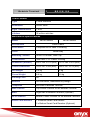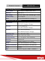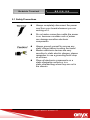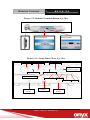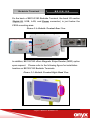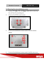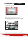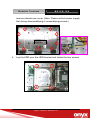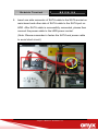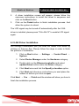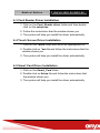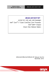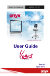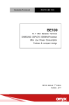
1
Bedside Terminal BE150/180 BE150/180 15.6”/18.5” Bedside Terminal Intel® AtomTM N270 Processor High Performance Low Power Consumption Wide LCD with Multimedia BE150/180 Manual 1st Edition June. 2010 Bedside Terminal BE150/180 Copyright Notice This document is copyrighted, 2010. All rights are reserved. The original manufacturer reserves the right to make improvements to the products described in this manual at any time without notice. No part of this manual may be reproduced, copied, translated, or transmitted in any form or by any means without the prior written permission of the original manufacturer. Information provided in this manual is intended to be accurate and reliable. However, the original manufacturer assumes no responsibility for its use, nor for any infringements upon the rights of third parties, which may result from its use. The material in this document is for product information only and is subject to change without notice. While reasonable efforts have been made in the preparation of this document to assure its accuracy, ONYX Healthcare Inc., assumes no liabilities resulting from errors or omissions in this document, or from the use of the information contained herein ONYX Healthcare Inc. reserves the right to make changes in the product design without notice to its users Bedside Terminal BE150/180 Acknowledgments Intel® and Atom™ N270 are registered trademarks of Intel ® Corporation. IBM, PC/AT, PS/2 are trademarks of International Business Machines Corporation. Microsoft® Windows is a registered trademark of Microsoft ® Corporation. RTL is a trademark of Realtek Semi-Conductor Co., Ltd. C&T is a trademark of Chips and Technologies, Inc. UMC is a trademark of United Microelectronics Corporation. ITE is a trademark of Integrated Technology Express, Inc. SiS is a trademark of Silicon Integrated Systems Corp. VIA is a trademark of VIA Technology, Inc. All other product names or trademarks are properties of their respective owners. Bedside Terminal BE150/180 Packing List Before you begin installing your Bedside Terminal, please make sure that the following items have been shipped: BE150 or BE180 Bedside Terminal. VESA Mount Screws Utility CD-ROM (Please insert the ONYX-BE150/180 CD-ROM into external CD-ROM drive.) which Contains User’s Manual (in PDF format), Drivers and Utilities If any of these items are missing or damaged, you should contact your distributor or sales representative immediately. Headquarters Onyx Healthcare Inc. 2F, No.135, Lane 235, Pao-Chiao Rd., Hsin-Tien City, Taipei 231, Taiwan, R.O.C. TEL: +886-2-8919-2188 FAX: +886-2-8919-1699 E-mail: [email protected] http://www.onyx-healthcare.com Bedside Terminal BE150/180 Worldwide Offices: Onyx Healthcare, USA Inc. 2663 Saturn street, Brea, CA 92821, USA Tel : +1-714-996-1800 Fax: +1-714-996-1811 Email: [email protected] Onyx Healthcare EUROPE B.V. Ekkersrijt 4002, 5692 DA Son, The Netherlands Tel : +31-(0)499-462020 Fax: +31-(0)499-462010 Email: [email protected] Onyx Healthcare Technology GmbH An der Trift65d 63303 Dreieich , Germany TEL: +49-(0)61033-7479-00 Fax: +49-(0)61033-7479-49 Email: [email protected] Bedside Terminal BE150/180 Onyx Healthcare (SU ZHOU) INC. Room 12, 2F, Building B, No.5 Xing Han Street, Suzhou Industrial Park, Jiang Su Province, China Tel: +86-512-67625700 Fax: +86-512-67617337 Email: [email protected] Onyx Healthcare Singapore PTE LTD 57 Genting Lane, #07-00, Singapore 349564 Tel: +65-67498749 Fax +65-67461595 Email: [email protected] Bedside Terminal BE150/180 Safety & Warranty 1. Read these safety instructions carefully. 2. Keep this user's manual for later reference. 3. Disconnect this equipment from any AC outlet before cleaning. Do not use liquid or spray detergents for cleaning. Use a damp cloth. 4. For pluggable equipment, the power outlet must be installed near the equipment and must be easily accessible. 5. Keep this equipment away from humidity. 6. Put this equipment on a reliable surface during installation. Dropping it or letting it fall could cause damage. 7. The openings on the enclosure are for air convection. Protect the equipment from overheating. DO NOT COVER THE OPENINGS. 8. Make sure the voltage of the power source is correct before connecting the equipment to the power outlet. 9. Position the power cord so that people cannot step on it. Do not place anything over the power cord. 10. All cautions and warnings on the equipment should be noted. 11. If the equipment is not used for a long time, disconnect it from the power source to avoid damage by transient over-voltage. 12. Never pour any liquid into an opening. This could cause fire or electrical shock. 13. Never open the equipment. For safety reasons, only qualified service personnel should open the equipment. Bedside Terminal BE150/180 14. If any of the following situations arises, get the equipment checked by service personnel: a. The power cord or plug is damaged. b. Liquid has penetrated into the equipment. c. The equipment has been exposed to moisture. d. The equipment does not work well, or you cannot get it to work according to the user’s manual. e. The equipment has been dropped and damaged. f. The equipment has obvious signs of breakage. 15. DO NOT LEAVE THIS EQUIPMENT IN AN UNCONTROLLED ENVIRONMENT WHERE THE STORAGE TEMPERATURE IS BELOW -20° C (-4°F) OR ABOVE 60° C (140° F). IT MAY DAMAGE THE EQUIPMENT. 16. External equipment intended for connection to signal input/output or other connectors, shall comply with relevant UL / IEC standard (e.g. UL 1950 for IT equipment and UL 60601-1 / IEC 60601 series for systems – shall comply with the standard IEC 60601-1-1, Safety requirements for medical electrical systems. Equipment not complying with UL 60601-1 shall be kept outside the patient environment, as defined in the standard. Caution: It may cause the danger of explosion if battery is incorrectly replaced. Replace only with same or equivalent type recommended by the manufacturer. Bedside Terminal BE150/180 Classification 1. Degree of production against electric shock: not classified 2. Degree of protection against the ingress of water: IPX1 3. Equipment not suitable for use in the presence of a flammable anesthetic mixture with air or with oxygen or nitrous oxide. 4. Mode of operation: Continuous 5. Type of protection against electric shock: Class I equipment Bedside Terminal BE150/180 FCC This device complies with Part 15 FCC Rules. Operation is subject to the following two conditions: (1) this device may not cause harmful interference, and (2) this device must accept any interference received including interference that may cause undesired operation. Bedside Terminal BE150/180 UL Module Description BE150/180 AC modules are developed to suitable for the Classification Mark requirement Bedside Terminal BE150/180 Safety Symbol Description The following safety symbols are the further explanations for your reference. Medical equipment with respect to electric shock, fire and mechanical hazards only in accordance with UL 60601-1, and CAN/CSA C22.2 NO. 601.1 Attention, consult ACCOMPANYING DOCUMENTS. Ground wire Protective Ground wire. Medical equipment with respect to electric shock, fire and mechanical hazards only in accordance with UL 60601-1, and CAN/CSA C22.2 NO. 601.1 Bedside Terminal BE150/180 Contents Chapter 1 General Information 1.1 Introduction ....................................................................1-2 1.2 Feature ............................................................................1-3 1.3 Specification...................................................................1-4 1.4 Dimension.......................................................................1-9 Chapter 2 Hardware Installation 2.1 Safety Precautions.........................................................2-2 2.2 A Quick Tour of the BE150/180.....................................2-3 2.3 Removing the rear maintenance cover........................2-6 2.4 Hard Disk Drive (2.5” HDD) Installation .......................2-7 Chapter 3 Award BIOS Setup 3.1 System Test and Initialization.......................................3-2 3.2 Award BIOS Setup. ........................................................3-3 3.3 Standard CMOS Features..............................................3-5 3.4 Advanced BIOS Features ..............................................3-5 3.5 Advanced Chipset Features..........................................3-5 3.6 Integrated Peripherals ...................................................3-5 3.7 Power management Setup ............................................3-5 3.8 PnP/PCI configuration ...................................................3-6 3.9 PC Health Status ............................................................3-6 3.10 Frequency/Voltage control..........................................3-6 3.11 Load Fail-Safe Defaults ...............................................3-6 Bedside Terminal BE150/180 3.12 Load Optimized Defaults.............................................3-7 3.13 Set Supervisor/User Password...................................3-7 3.14 Save & Exit Setup.........................................................3-8 3.15 Exit without saving ......................................................3-8 Chapter 4 Driver Installation 4.1 Installation ......................................................................4-2 4.2 Card Reader Driver Installation ....................................4-3 4.3 Touch Screen Driver Installation..................................4-4 4.4 Smart Card Driver Installation ......................................4-4 4.5 RFID Driver Installation .................................................4-4 Appendix A Miscellanea A.1 General Cleaning Tips.................................................. A-2 A.2 Cleaning Tools.............................................................. A-3 A.3 Scrap Computer Recycling ........................................ A-5 Bedside Terminal BE150/180 Chapter 1 General Information Chapter 1 General Information 1-1 Bedside Terminal BE150/180 1.1 Introduction —A bedside terminal solution for ultimate patient services that boosts patient satisfaction and well-beings. BE150/180 offers the highly scalable bedside infotainment solution to enhance patient experiences within the hospital. Packaged with renowned software solution partners, 15.6” BE150 and 18.5” BE180 bedside terminals provides patients with capabilities like Entertainment on Demand, Online Access, VoIP Phone, Nurse Call, etc. Clinical Applications Ward, Nursing Station/Cart Service Capabilities – BE150/180 Hospital Information Access – Patient Record Access Treatment Progress Reporting (i.e. Medical Charting) Dietary/Meal Ordering Service Monitoring/Communication – Doctor Consultation by Video Conference Internet Access VoIP Telephone Access Chapter 1 General Information 1-2 Bedside Terminal BE150/180 Entertainment on Demand Video-on-Demand TV/Radio Broadcasting 1.2 Feature 15.6”/18.5” Wide Color TFT LCD display Intel® ATOM™ N270 Processor Fanless & Compact Design VoIP phone, Web Camera, and High Quality Speaker Emergency Call/Nurse Call (Optional) Multimedia Entertainment: TV, Game, VoIP, Web Radio Mini PCI 802.11a/b/g Internal Wireless Antenna (optional) Chapter 1 General Information 1-3 Bedside Terminal BE150/180 1.3 Specification Model Number BE150/180 Model Description 15.6”/18.5” Low Power High Performance Bedside Terminal with Multimedia Main Specification CPU Processor Intel® Atom™ N270 1.6GHz Processor LCD Controller Intel®945GSE, Shared memory up to 224MB System Memory Up to 2GB DDRII 400/533/667 BE150: 15.6” Wide Color TFT LCD Display BE180: 18.5” Wide Color TFT LCD Windows® 7 (32 bit & 64 bit) Windows® XP Pro OS Support Windows® XP Embedded Fedora Core Internal Mini PCI for WLAN (Optional) TV Tuner Card (Optional) Magnetic Stripe Reader (Optional) Expansion Barcode Scanner (Optional) VoIP Phone Web Camera Bluetooth Chapter 1 General Information 1-4 Bedside Terminal BE150/180 Main Specification (Cont.) 1 x 2.5” HDD (SATA) 1 x Type II Compact Flash (internal on board Storage Disk Drive socket) 1 x Smart Card Reader 1 x Smart Card Reader/RFID Module (Optional) Brightness: “+” / ”-“; Sound: “+” / ”-“; LCD On/Off; Button Barcode Trigger (optional) /Nurse Call Button (optional) 1 x Web Camera (1.3M Pixel) 2 x Alarm Light (Can be removed by request) Accessory 1 x Nurse Call Connector (optional) 1 x Buzzer (GPIO Controllable – On/Off/Volume) 1 x MSR (TTL Interface) 1 x Bottom Barcode Reader (RS-232 Interface) Accessory (Optional) 1 x RFID (USB Interface shared with Smart Card Reader) Support Content IP TV, Web Gaming, MPEG 2/3/4, Web Radio I/O 1 x Line out / MIC in (GPIO controllable, Audio mute/volume) 2 x External USB2.0 (on bottom I/O), 3 x Internal USB USB2.0 Chapter 1 General Information 1-5 Bedside Terminal BE150/180 Serial port 1 x DIO Connector for Hardwire Nurse Call Ethernet 1 x Gigabit Ethernet (Support WOL) I/O (Cont.) Video 1 x Video-in through TV Tuner Card (Optional) Speaker 2 x 2W High Quality Speakers LCD Specification BE150 Series Model Display Type 15.6” Color TFT LCD 16.7M Max. Colors Luminance (cd/m2) 18.5” Color TFT LCD 1366 x 768 Max. Resolution Dot Size (mm) BE180 Series 0.252 x 0.252 0.3 x 0.3 250 nits 300 nits 55/55(H right/Left) View Angle 30/55 (V upper/lower) Contrast Ratio Back Light MTBF 500:1 1000:1 50,000 Hrs Note: All ONYX's LCD products are manufactured with High precision technology. However, there are a small number of defective pixels in all LCD panels that are not able to change color. This is a normal occurrence for all LCD displays from all manufacturers and should not be noticeable or objectionable under normal operation. ONYX LCD panels are qualified for industry standard conditions in the following: total 7 dead pixels on a screen or if there are 3 within 1 inch square area of each other on the display. Chapter 1 General Information 1-6 Bedside Terminal BE150/180 Touch Screen Type 5 Wire Resistive Resolution 2048 x 2048 Light Transmission > 80% Lifetime 35 million activities Mechanical Specifications BE150 Series Model Close-Frame Architecture Front Bezel BE180 Series Complete flat for ease of cleaning White/Gray Color Mounting / Holder VESA 75/100mm, Desk Top Construction 3mm ABS + PC Plastic Housing Dimension (WxHxD) 430 x 324 x 61.9 (mm) 510 x 385 x 60.9 (mm) Carton Dimension 724 x 327 x 545 (mm) 806 x 327 x 612 (mm) Net Weight 5.0 kg 6 kg Gross Weight 8.0 kg 10 kg Packing Filler PE Buttons On front bezel, membrane key design Telephone Left side of Bedside Terminal Web Camera Top Center Position on the Bedside Terminal MSR Right side of Bedside Terminal (Optional) RFID Scanner Bottom Center Position on the Bedside Terminal Smart Card Readers 1 x Bottom Smart Card Reader 2 x Bottom Smart Card Readers (Optional) Chapter 1 General Information 1-7 Bedside Terminal BE150/180 Power Supply Requirement Power Supply FSP Group Inc. Adapter Mode: 120 W Model No. PMP120-14 Input Voltage AC: 100 ~ 240V; 1.4A ~ 0.6A Max. @ 47 ~ 63Hz Output Voltage DC: 24V @ 5A MTBF 150,000 hrs minimum at full load @ 25°C Environmental Specification Temperature 10~35°C(Operating) / -20°C~60°C (Transport / Storage) Humidity 30~75%(Operating) / 10°C~90°C (Transport / Storage) Pressure 850~1000hPa(Operating) / 850~1000hPa(Transport / Storage) Operating Temp. 0°C ~ 35°C (32°F ~ 95°F) Storage Temp. -20°C ~ 60°C (-4°F ~140°F) Storage Humidity 5% ~ 95% @ 40°C, Non-Condensing Mounting VESA75/100 Vibration Random Operation 0.5G, 5~500Hz Shock 15G Peak Acceleration (11ms. Duration) Degree of Protection IP65 on Front Panel/IPX1 on Whole Unit Noise Fanless EMC CE/FCC Class B, UL 60601-1, EN60601-1 Chapter 1 General Information 1-8 Bedside Terminal BE150/180 1.4 Dimension Bedside Terminal BE150 Bedside Terminal BE180 Chapter 1 General Information 1-9 Bedside Terminal BE150/180 Chapter 2 Hardware Installation Chapter 2 Hardware Installation 2-1 Bedside Terminal BE150/180 2.1 Safety Precautions Always completely disconnect the power cord from your board whenever you are working on it. Do not make connections while the power is on, because a sudden rush of power can damage sensitive electronic components. Always ground yourself to remove any static charge before touching the board. Modern electronic devices are very sensitive to static electric charges; please remember to use a grounding wrist strap at all times. Place all electronic components on a static-dissipative surface or in a static-shielded bag when they are not in the chassis. Chapter 2 Hardware Installation 2-2 Bedside Terminal BE150/180 2.2 A Quick Tour of the BE150/180 Before you start to set up the BE150/180, please take a moment to familiarize yourself with the locations and purposes of the controls, drives, connections and ports. The following figures illustrate the fully loaded bedside terminal with all applicable options. Picture 2.1: Bedside Terminal Front Panel View Chapter 2 Hardware Installation 2-3 Bedside Terminal BE150/180 Picture 2.2: Bedside Terminal Bottom-Up View Picture 2.3: Front Panel Closer Up View LCD On/Off Brightness: + Volume: -- Barcode Scanner Trigger Brightness: -- Volume: -- Barcode Scanner USB Power on/off Line Out Smart Card Reader RFID Scanner Smart Card Reader Chapter 2 Hardware Installation 2-4 MIC-in Bedside Terminal BE150/180 On the back of BE150/180 Bedside Terminal, the back I/O section (Digital IO, USB, LAN, and Power connector) is just below the VESA mounting area. Picture 2.4: Bedside Terminal Rear View In addition, BE150/180 offers Magnetic Stripe Reader (MSR) option upon request. Please refer to the following figure for installation location on BE150/180 Bedside Terminals. Picture 2.5: Bedside Terminal Right Hand View Chapter 2 Hardware Installation 2-5 Bedside Terminal BE150/180 2.3 Removing the rear maintenance cover 1. Unplug USB, DIO, LAN, and Power cables before removing the unit from the mounting arm. 2. Unscrew the VESA mount screws. 3. Unscrew the attachment screws used to hold the fanless design. 4. Unscrew the attachment screws used to hold the rear cover Chapter 2 Hardware Installation 2-6 Bedside Terminal BE150/180 and remove the rear cover. 2.4 Hard Disk Drive (2.5” HDD) Installation 1. Remove the rear cover as previously instructed. 2. Unscrew the attachment screw on internal I/O section and remove internal I/O section cover. 3. Unscrew the attachment screws on internal rear cover and Chapter 2 Hardware Installation 2-7 Bedside Terminal BE150/180 remove internal rear cover. (Note: Please un/lock power supply first during disassemblying or assemblying process.) Un/lock Power Supply First 4. Lay the HDD over the HDD bracket and fasten the four screws Chapter 2 Hardware Installation 2-8 Bedside Terminal BE150/180 5. Insert one side connector of SATA cable to the SATA socket on main board and other side of SATA cable to the SATA port on HDD. After SATA cable is successfully connected, please then connect the power cable to the HDD power socket. (Note: Please remember to fasten the SATA and power cable to avoid short circuit.) Chapter 2 Hardware Installation 2-9 Bedside Terminal BE150/180 Chapter 3 Award BIOS Setup Chapter 3 Award BIOS Setup 3-1 Bedside Terminal BE150/180 3.1 System Test and Initialization These routines test and initialize board hardware. If the routines encounter an error during the tests, you will either hear a few short beeps or see an error message on the screen. There are two kinds of errors: fatal and non-fatal. The system can usually continue the boot up sequence with non-fatal errors. Non-fatal error messages usually appear on the screen along with the following instructions: Press <F1> to RESUME Write down the message and press the F1 key to continue the boot up sequence. System configuration verification These routines check the current system configuration against the values stored in the CMOS memory. If they do not match, the program outputs an error message. You will then need to run the BIOS setup program to set the configuration information in memory. There are three situations in which you will need to change the CMOS settings: 1. You are starting your system for the first time 2. You have changed the hardware attached to your system 3. The CMOS memory has lost power and the configuration information has been erased. The ONYX-BE150/180 SD CMOS memory has an integral lithium battery backup for data retention. However, you will need to replace the complete unit when it finally runs down. Chapter 3 Award BIOS Setup 3-2 Bedside Terminal BE150/180 3.2 Award BIOS Setup Awards BIOS ROM has a built-in Setup program that allows users to modify the basic system configuration. This type of information is stored in battery-backed CMOS RAM so that it retains the Setup information when the power is turned off. Entering setup Power on the computer and press <Del> immediately. This will allow you to enter Setup. Standard CMOS Features Use this menu for basic system configuration. (Date, time, IDE, etc.) Advanced BIOS Features Use this menu to set the advanced features available on your system. Advanced Chipset Features Use this menu to change the values in the chipset registers and optimize your system performance. Integrated Peripherals Use this menu to specify your settings for integrated peripherals. (Primary slave, secondary slave, keyboard, mouse etc.) Power Management Setup Use this menu to specify your settings for power management. (HDD power down, power on by ring etc.) Chapter 3 Award BIOS Setup 3-3 Bedside Terminal BE150/180 PnP/PCI Configurations This entry appears if your system supports PnP/PCI. PC Health Status This menu shows you the status of PC. Frequency/Voltage Control This menu shows you the display of frequency/Voltage Control. Load Fail-Safe Defaults Use this menu to load the BIOS default values for the minimal/ stable performance for your system to operate. Load Optimized Defaults Use this menu to load the BIOS default values that are factory settings for optimal performance system operations. While AWARD has designated the custom BIOS to maximize performance, the factory has the right to change these defaults to meet their needs. Set Supervisor/User Password Use this menu to set Supervisor/User Passwords. Save and Exit Setup Save CMOS value changes to CMOS and exit setup. Exit Without Saving Abandon all CMOS value changes and exit setup. Chapter 3 Award BIOS Setup 3-4 Bedside Terminal BE150/180 3.3 Standard CMOS Features Choosing the Standard CMOS Features option from the INITIAL SETUP SCREEN menu, and the standard Setup Menu allows users to configure system components such as date, time, hard disk drive, floppy drive and display. Once a field is highlighted, on-line help information is displayed in the right box of the Menu screen. 3.4 Advanced BIOS Features Choosing the Advanced BIOS Features option from the INITIAL SETUP SCREEN menu, and you will see this screen contains the manufacturer’s default values for the ONYX-BE150/BE180. 3.5 Advanced Chipset Features Choosing the Advanced Chipset Features option from the INITIAL SETUP SCREEN menu, and you will see the screen contains the manufacturer’s default values for the ONYX-BE150/BE180. 3.6 Integrated Peripherals Choosing the Integrated Peripherals from the INITIAL SETUP SCREEN menu, and you will see the screen contains the manufacturer’s default values for the ONYX-BE150/BE180. 3.7 Power management Setup Choosing the Power Management Setup from the INITIAL SETUP SCREEN menu, and the screen contains the Chapter 3 Award BIOS Setup 3-5 Bedside Terminal BE150/180 manufacturer’s default values for the ONYX-BE150/BE180. 3.8 PnP/PCI configuration Choosing the PnP/PCI configurations from the Initial Setup Screen menu, and you will see the screen contains the manufacturer’s default values for the ONYX-BE150/BE180. 3.9 PC Health Status Choosing the PC Health Status from the Initial Setup Screen menu, and you will see the screen contains the manufacturer’s default values for the ONYX-BE150/BE180. 3.10 Frequency/Voltage control Choosing the Frequency/Voltage Control from the Initial Setup Screen menu, and you will see the screen contains the manufacturer’s default values for the ONYX-BE150/BE180. 3.11 Load Fail-Safe Defaults When you press <Enter> on this item you get a confirmation dialog box with a message similar to: Load Fail-Safe Default (Y/N)? Pressing "Y" loads the BIOS default values for the most stable, minimal performance system operations. Chapter 3 Award BIOS Setup 3-6 Bedside Terminal BE150/180 3.12 Load Optimized Defaults When you press <Enter> on this item you get a confirmation dialog box with a message similar to: Load Optimized Defaults (Y/N)? Pressing "Y" loads the default values that are manufacturer’s settings for optimal performance system operations. 3.13 Set Supervisor/User Password You can set either SUPERVISOR or USER PASSWORD, or both of them. The difference between the two is that the supervisor password allows unrestricted access to enter and change the options of the setup menus, while the user password only allows entry to the program, but not modify options. To abort the process at any time, press Esc. In the Security Option item in the BIOS Features Setup screen, select System or Setup: System Enter a password each time the system boots and whenever you enter Setup. Setup Enter a password whenever you enter Setup. NOTE: To clear the password, simply press Enter when asked to enter a password. Then the password function is disabled. Chapter 3 Award BIOS Setup 3-7 Bedside Terminal BE150/180 3.14 Save & Exit Setup If you select this option and press <Enter>, the values entered in the setup utilities will be recorded in the chipset’s CMOS memory. The microprocessor will check this every time you turn on your system and compare this to what it finds as it checks the system. This record is required for the system to operate. 3.15 Exit without saving Selecting this option and pressing <Enter> allows you to exit the Setup program without recording any new value or changing old one. For more detailed information, you can refer to the "ONYX BIOS Item Description.pdf" file in the CD for the meaning of each setting in this chapter. Chapter 3 Award BIOS Setup 3-8 Medical Station ONYX-BE150/BE180 Chapter 4 Driver Installation Chapter 4 Driver Installation 4-1 Medical Station ONYX-BE150/BE180 There are several installation ways depending on the driver package under different Operating System application. Please insert the BE-150/180 Utility CD-ROM into the UL approved external CD-ROM drive. Please follow the sequence below to install the drivers: Step 1 – Install Intel INF Update for Windows 9x-2003 Driver Step 2 – Install Intel Graphics Media Accelerator Driver Step 3 – Install Intel LAN Driver Step 4 – Install Realtek AC97 codec Driver Touch Screen Driver Installation Card Reader Driver Installation Smart Card Driver Installation Barcode scanner Driver Installation USB 2.0 Drivers are available for download using Windows Update for both Windows XP and Windows 2000. For additional information regarding USB 2.0 support in Windows XP and Windows 2000, please visit www.microsoft.com/hwdev/usb/. For installation procedures of each driver, you may see the details in the following. 4.1 Installation Applicable for Windows 9x-2003 1. Place the CD into DVD-ROM. The CD automatically displays the drivers menu if Autorun is enabled in your computer. If Autorun is NOT enabled in your computer, browse the contents of the support to locate the file AUTORUN.EXE to run the CD. Chapter 4 Driver Installation 4-2 Medical Station ONYX-BE150/BE180 2. A driver installation screen will appear, please follow the onscreen instructions to install the driver in sequence and click on the Next button. 3. Click on the Finish button to finish installation process. And allow the system to reboot. The LCD signal may be turned off automatically after the VGA driver is installed, please press "Ctrl+Alt+F3" to enable LCD signal again. 4.2 LAN Driver Installation We strongly recommend that you shall not install LAN driver by clicking on Autorun Exe. Please follow the steps in order to finish the process of installation. 1. Click on Start button → Settings → Control Panel → System 2. Select Device Manager under the Hardware category. 3. Double click on the Ethernet controller and select update Driver button under the Driver category. 4. Click Next twice and tick the Specify a location option. 5. Click Next and choose a route where you want place the folders on before you click on open. Click Next → Yes → Finish and the window will show you how to finish the installation process. Chapter 4 Driver Installation 4-3 Medical Station ONYX-BE150/BE180 4.3 Card Reader Driver Installation 1. Click on the Card_Reader driver folder and then double click on the setup.exe 2. Follow the instructions that the window shows you 3. The system will help you install the driver automatically 4.4 Touch Screen Driver Installation 1. Click on the Touch folder and select an appropriate OS 2. Double click on *exe file and follow the instructions that the window shows you 3. The system will help you install the driver automatically 4.5 Smart Card Driver Installation 1. Click on the Smart_Card folder 2. Double click on Setup file and follow the instructions that the window shows you 3. The system will help you install the driver automatically Chapter 4 Driver Installation 4-4 Bedside Terminal BE150/180 Appendix A Miscellaneous Appendix A Miscellaneous A-1 Bedside Terminal BE150/180 A.1 General Cleaning Tips Please refer to the following precautions and fully understand the warning details prior to cleaning the device. 1. Never spray or squirt the liquids directly onto any computer component. If you need to clean the device, please rub it with a piece of dry cloth. 2. Be cautious of the tiny removable components when you use a vacuum cleaner to absorb the dirt on the floor. 3. Turn the system off before you start to clean up the component or computer. 4. Never drop the components inside the computer or get circuit board damp or wet. 5. Be cautious of all kinds of cleaning solvents or chemicals when you use it for the sake of cleaning. Some individuals may be allergic to the ingredients. 6. Try not to put any food, drink or cigarette around the computer. 7. Please remember to clean up the computer by weekly. 8. ONYX Healthcare Inc. has tested and verified these cleaning disinfectants, CIDEX, Viraguard, Control III Disinfectant Germicide, Caviwipes, Dispatch Disinfectant Cleaner CLH69101, Puregreen 24 Disinfectant, can be used with the BE150/180. Use of any other disinfectants will void the warranty. Appendix A Miscellaneous A-2 Bedside Terminal BE150/180 A.2 Cleaning Tools Although many companies have created products to help improve the process of cleaning your computer and peripherals users can also use household items to clean their computers and peripherals. Below is a listing of items you may need or want to use while cleaning your computer or computer peripherals. Keep in mind that some components in your computer may only be able to be cleaned using a product designed for cleaning that component, if this is the case it will be mentioned in the cleaning tips. Cloth - A piece of cloth is the best tool to use when rubbing up a component. Although paper towels or tissues can be used on most hardware as well, we still recommend you to rub it with a piece of cloth. Water or rubbing alcohol – You may moisten a piece of cloth a bit with some water or rubbing alcohol and rub it on the computer. Unknown solvents may be harmful to the plastics parts. Vacuum cleaner - Absorb the dust, dirt, hair, cigarette particles, and other particles out of a computer can be one of the best methods of cleaning a computer. Over time these items can restrict the airflow in a computer and cause circuitry to corrode. Appendix A Miscellaneous A-3 Bedside Terminal BE150/180 Cotton swabs - Cotton swaps moistened with rubbing alcohol or water are excellent tools for wiping hard to reach areas in your keyboard, mouse, and other locations. Foam swabs - Whenever possible it is better to use lint free swabs such as foam swabs. Note: 1. We strongly recommended that you should shut down the system before you start to clean any components. 2. Please remember to clean up your computer every day. Please follow the steps below before cleaning the device. 1. Close all application programs. 2. Close operating software. 3. Turn off power switch 4. Remove all device 5. Pull out power cable Appendix A Miscellaneous A-4 Bedside Terminal BE150/180 A.3 Scrap Computer Recycling If the computer equipments need the maintenance or are beyond repair, we strongly recommended that you should inform us as soon as possible for the suitable solution. For the computers that are no longer useful or work well, please contact with worldwide distributors for recycling. Note: Please follow the national requirement for unit disposal. Appendix A Miscellaneous A-5