1
Freescale Semiconductor
Application Note
Document Number: AN2573
Rev. 2, 01/2007
LINkits LIN Evaluation Boards
by: Peter Topping
East Kilbride
1
Introduction
This application note describes the demonstration
application that is programmed into the LINkits
evaluation boards. The LINkits boards comprise two
LIN masters (MC68HC9S12C32/D64 and
MC68HC908GZ60) and four slaves
(MC68HC908GR60, MC68HC908EY16,
MC68HC908QY4, and MC68HC908QL4). These
devices will be referred to as the 9S12C32, 9S12D64,
GZ60, GR60, EY16, QY4, and QL4, respectively. At the
time of publication, QL4 silicon was unavailable so this
board is not described.
The application runs using either of the masters and any
combination of as many as 16 slaves (maximum of 4
slaves of any one type). This is achieved by using
different default LIN IDs for each type of slave and by
allowing this ID to be easily changed to any one of the
three other IDs for that particular slave. If no more than
one slave of any type is in use, no modification from the
default IDs is necessary.
© Freescale Semiconductor, Inc., 2006. All rights reserved.
Contents
1
Introduction . . . . . . . . . . . . . . . . . . . . . . . . . . . . . . . . . . . 1
2
LINkits Demonstration Application. . . . . . . . . . . . . . . . . . 2
3
Hardware . . . . . . . . . . . . . . . . . . . . . . . . . . . . . . . . . . . . . 3
4
Master Software . . . . . . . . . . . . . . . . . . . . . . . . . . . . . . . 5
5
Slave Software . . . . . . . . . . . . . . . . . . . . . . . . . . . . . . . . 7
6
CodeWarrior Project . . . . . . . . . . . . . . . . . . . . . . . . . . . 10
7
References . . . . . . . . . . . . . . . . . . . . . . . . . . . . . . . . . . 11
8
MC68HC9S12C32 Master Software Listings . . . . . . . . 11
Appendix AMaster.h . . . . . . . . . . . . . . . . . . . . . . . . . . . . . . . 17
Appendix BMaster.id . . . . . . . . . . . . . . . . . . . . . . . . . . . . . . . 18
Appendix CMaster.cfg . . . . . . . . . . . . . . . . . . . . . . . . . . . . . . 19
Appendix DVector.c . . . . . . . . . . . . . . . . . . . . . . . . . . . . . . . . 20
9
MC68HC908EY16 Slave Software Listings. . . . . . . . . . 23
10 HC08EY16.h
(Register Definitions for the MC68HC908EY16) . . . . . . . . . . 27
Appendix ESlave.id (LIN Message ID File) . . . . . . . . . . . . . . 29
Appendix FSlave.cfg (LIN Configuration File) . . . . . . . . . . . . 29
Appendix G#define VECTOR_C . . . . . . . . . . . . . . . . . . . . . . 31
LINkits Demonstration Application
In order to retain versatility in the selection of the MCUs used for the master and slave nodes, the boards
are available separately. There is also an accessory kit that includes a 500-mA power supply, an RS-232
cable, and a CD containing the documentation and software. This includes the application programs and
the LIN drivers for each node, allowing users to develop their own LIN applications using the LINkits
boards. The RS-232 cable is required to connect the LINkits board to a PC running the Metrowerks’
CodeWarrior® development environment. This cable is not part of the programmed demonstration
application.
Each slave has four LEDs whose states can be controlled by a single push-button switch. The resulting
four bits of data is returned to the master and displayed on four of its eight LEDS. The other four LEDs on
the master are used to indicate the slave type and ID. Two LEDs show the slave type (GR, EY, QY, or QL)
and the other two correspond to the four IDs allocated to that particular type. If more than one slave is
connected, the master’s display cycles round all those present on the bus. The sending of header frames
from the master can also be switched off to demonstrate the slaves’ ability to enter low-power sleep mode
in the absence of LIN activity (not applicable to the QY4 slave).
NOTE
With the exception of mask set errata documents, if any other Motorola
document contains information that conflicts with the information in the
device data sheet, the data sheet should be considered to have the most
current and correct data.
2
LINkits Demonstration Application
The master has two modes selected by its slide switch. In one mode, a single lit LED sweeps up and down
the display indicating that no LIN header frames are being sent. In this mode any slaves connected should
be in sleep mode.
With the switch in the other position, the master sends headers for all the IDs used in the demonstration
application and checks to see which are actually present. If a slave is present, the identification code and
data is displayed in turn for all the IDs for which a response is received. The IDs used are shown in Table 1.
Table 1. The LIN IDs Used by Each Type of Slave
Slave
Default ID
Configurable IDs
Master LED ID Code
(d: default)
Alternative IDs
GR60
$29
$2A, $2B & $28
1101 (d), 1110, 1111 & 1100
$2C, $2D, $2E & $2F
EY16
$21
$22, $23 & $20
1001 (d), 1010, 1011 & 1000
$24, $25, $26 & $27
QY4
$19
$1A, $1B & $18
0101 (d), 0110, 0111 & 0100
$1C, $1D, $1E & $1F
QL4
$11
$12, $13 & $10
0001 (d), 0010, 0011 & 0000
$14, $15, $16 & $17
The master cycles round the IDs of all the slaves that it finds to be present and displays each slave’s ID
using the bottom (leftmost) four LEDs. The two leftmost LEDs show the slave type, and the next two
LEDs show the two LSBs of its ID using the code shown in Table 1.
LINkits LIN Evaluation Boards, Rev. 2
2
Freescale Semiconductor
Hardware
The choice of IDs, their display formats, and the skipping of zero in the data field ensure that there is at
least one 1 in each 4-bit field. These provisions eliminate the possibility of an all-zero slave display (which
would also be represented in the master display by no illuminated LEDs). The only exception to this is the
ID field displayed by the master for the last configurable QL ID ($10).
Slaves can be added or removed from the bus without powering down or resetting the boards. When the
master recognizes a new slave, it indicates this by sweeping the LED display once from 0 to 7. It then adds
this slave to its display sequence. When it loses a slave, it shows this by sweeping the LEDs from 7 to 0
and removing it from the display sequence.
Out of reset, each slave responds with two bytes of data using its default ID. When in normal mode (not
ID configuration mode), the push-button increments the LEDs through a binary cycle of 1–15, skipping
zero. This 4-bit number is displayed on the slave’s LEDs and also on the top (rightmost) four bits of the
master’s LED display. It is transferred to the master using the lower four bits of the first data byte of the
slave’s response.
The simple user interface uses a single push-button switch and four LEDs, and it allows the ID to be
changed to any of the three configurable IDs (or back to the default ID). This configuration mode is entered
by holding the button down for three seconds. In this mode, the LEDs flash and indicate the current ID.
The button then allows cycling through the four configurable IDs (first LED for ID --xx xx01, second for
--xx xx10, third for --xx xx11, and fourth for --xx xx00). If the button is not pressed for three seconds, the
mode returns to normal.
The sleep feature of the boards can be seen by switching off the master’s LIN activity while the slaves are
connected and running. After five seconds, the boards (GR60 and EY16 only) will go to sleep as
represented by all the LEDs switching off. This feature is not supported by the QY4 slave.
The allocation of the four alternative IDs for each slave type shown in Table 1 allows as many as eight
slaves of one type to be used without reallocating any other IDs. These alternative IDs are, however, not
supported by the programmed demonstration application.
3
Hardware
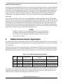
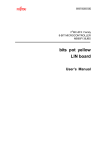
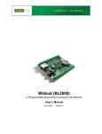
Figure 1 shows the main circuit diagram of the MC68HC908EY16 LINkits slave board. This constitutes
the complete LIN node and also shows the function of the three jumpers on the board. These jumpers are
only required when using the board to program or debug application software and should not be inserted
when running the demonstration program (a fourth jumper, J3, — only on the QY4 slave — should be
inserted when running the demonstration program).
When in the debug mode, additional hardware is required to connect the LINkits board to the PC
containing the development environment. For clarity, these interfaces are not shown in Figure 1. The
complete circuit diagram also shows the two 20-way connectors, P1 and P2. These allow access to all of
the MCU’s pins and facilitate the addition of a “top-board” incorporating user application hardware. Given
the different resources and pin-outs of the various devices, the pin-outs of P1 and P2 are as consistent as
possible across all the boards. The masters have additional pins available on a third 20-way connector, P3.
The basic circuit diagram of a LIN slave node is very simple. It comprises the MCU, the LIN physical
interface, and a 5-volt regulator. In this case, the physical interface used is the MC33399 (or MC33661)
LINkits LIN Evaluation Boards, Rev. 2
Freescale Semiconductor
3
Hardware
and the regulator is an LT1121, though these two chips can be replaced by a single chip, the MC33689
(LIN SBC systems base chip). The MCU enables the MC33399, which controls the regulator. When there
is no LIN activity, the MC33399 shuts down the regulator, thus powering down the MCU and putting the
node to sleep with an IDD of less than 50 μ1. This can be seen by the LEDs switching off because the
demonstration software is written in such a way that at least one LED is always on when the MCU is
powered up. An absence of LIN bus activity will not cause the MC68HC908QY4 to go to sleep.
~12 V
VBat
8
1
LT1121
5V
3
5
2.2 kΩ
1 kΩ
J2
(MONITOR
MODE)
J3
27 kΩ
LIN
6
7
VSup
8
INH
LIN
MC33399
3 WAKE
GND
5
10 kΩ
GND
17
5 V (DEBUG)
47 kΩ
IRQ
100 kΩ
47 kΩ
100 kΩ
28
29
30
VDD
VDDA
VREFH
100 nF
13
RESET
A4
RESET
31
PUSH-BUTTON
S1
9.1 V
ZENER
EN 2
9
Rx 1
Tx 4
24
E1
(ESCI)
23
E0
B5
OSCILLATOR MODULE
6
(DEBUG)
OSC1
J4
MC68HC908EY16
18
B0
14
B1
12
B2
11
B3
VSS
VSSA
VREFL
27
26
25
1 kΩ 1 kΩ 1 kΩ 1 kΩ
Figure 1. MC68HC908EY16 LINkits Slave
The other slaves are very similar to the EY16. The 48-pin GR60 is intended for use in high-end LIN nodes.
It does not have an on-chip clock generator and thus the PCB incorporates a crystal and its associated
passive components.
The QY4 is aimed at low-end nodes and, like the EY16, has an on-chip clock and thus does not require an
external crystal. It has an additional jumper (J3) to isolate PTA1 because it is required to be high for
monitor mode entry. This jumper should be fitted for normal use and removed only when entering monitor
mode.
The GZ60 master board is similar to the GR60 slave, but the GZ60 includes an MC33388 CAN interface.
The master boards also have a co-axial socket to allow the connection of the 12-V power supply included
in the accessory kit. This is primarily intended for use with the demonstration application because all the
LIN kits boards have two 4-pin, 8-amp Molex connectors (LIN, 12 volts and 2 grounds). These are
intended for daisy-chaining multiple slaves but can also be used to supply power.
The 9S12C32 master board is similar to the GZ60, but the MON08 interfaces of the 9S12C32 are replaced
by a 6-pin background debug mode (BDM) connector. As a possible low-cost alternative to the use of the
1. To achieve this current, the LED attached to the 12-V line should be removed from the board.
LINkits LIN Evaluation Boards, Rev. 2
4
Freescale Semiconductor
Master Software
BDM interface, the 9S12 PCB includes an RS-232 interface. This will, however, only be convenient to use
if the MCU fitted is an 9S12D64 (which has a second SCI) rather than an 9S12C32.
All the HC08 PCBs have two debug interfaces which allow engineering use of the boards in monitor mode.
These are the 16-pin Cyclone®/MultiLink® interface and an RS-232 connection directly to the PC via a
9-pin D connector. The RS-232 connection uses a level translator and an oscillator module. These are
powered up using the appropriate jumper (J3 for the EY16 board). This jumper also supplies a pullup on
the enable line to the MC33399 to prevent a power down when the reset button is pressed in the absence
of LIN activity. With no LIN activity, the node would normally be powered down, but this jumper prevents
this from happening in debug mode. This debug jumper should also be inserted when using the
Cyclone/MultiLink interface. Although this supply may not be required, applying 5 V to the RS-232
interface chip prevents contention on PTA0 I/O line. The inclusion of the jumper also ensures that the
oscillator module, which can optionally be used in this mode, is powered up.
When using the RS-232 MON08 interface, 9 V is required on the IRQ pin in order to enter monitor mode.
To achieve this, the appropriate jumper (J2 on the EY16 board) should be fitted. This mode also requires
a clock source and an additional jumper (J4 on the EY16 board) should be used to connect the oscillator
module to the OSC1 pin. This jumper is also required when using the Cyclone/MultiLink interface with
an external clock selected.
Cyclone® and MultiLink® are registered trademarks of P&E Microcomputer Systems, Inc.
4
Master Software
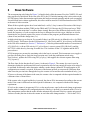
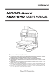
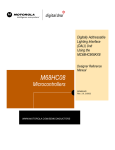
The flow chart of the master code is shown in Figure 2. The code itself is listed at the end of this document.
After MCU and LIN driver initialization, the slide switch on the PCB is checked to see if LIN activity
should be active. If not, a continuous sweeping LED display is enabled. If, however, LIN activity is
required, the while(1) loop in the master’s main() function continually cycles round the 16 IDs used in the
demonstration application (see Table 1). This is done using the array idList[16], which is initialized to
contain all the defined IDs. If LIN_MsgStatus() indicates that there is a response for a particular ID, its data
is read and its byte in the array activeList[16] is checked to see if this is a new node (it wasn’t previously
present). If so its byte is set to a 1 and NewNode() is executed to perform the LED display which indicates
that a node has been added.
If there is no response to a particular ID, activeList[16] is checked to determine whether there was a
response to that ID the previous time around the loop. If there was a response the previous time, the node
has since been removed. This is indicated on the LEDs using LostNode(). NewNode() and LostNode() are
also used to provide the continuous sweeping LED display when the LIN master is not active. This is
determined in the function LINActive(), which reads the slide switch on the master PCB.
LINkits LIN Evaluation Boards, Rev. 2
Freescale Semiconductor
5
Master Software
INITIALIZE PORTS AND LIN DRIVERS.
ENABLE INTERRUPTS.
READ SLIDE SWITCH
LIN ENABLED
?
NO
IDLE DISPLAY
NO LIN ACTIVITY
YES
YES
LastID
?
NO
SEND HEADER FRAME
CHECK LIN DRIVER STATUS
PENDING
?
YES
NO
NO
WAS ACTIVE
?
YES
“LOST NODE” DISPLAY
AND CLEAR FLAG
NO
RESPONSE
?
YES
GET DATA FROM SLAVE
ALREADY ACTIVE
?
YES
NO
“NEW NODE” DISPLAY
AND SET FLAG
DISPAY DATA AND ID
LOOP DELAY
NEXT ID
Figure 2. MC68HC9S012C32 Master Software Flow Chart
LINkits LIN Evaluation Boards, Rev. 2
6
Freescale Semiconductor
Slave Software
5
Slave Software
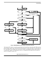
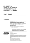
The accompanying code listing for Figure 3 is listed in back of this document. First, the CONFIG, I/O, and
timer registers are initialized. In the case of the EY16, the ICG initial trimming value is also written to the
ICGTR register. In the demonstration application, this has been entered manually and the code recompiled
for each board; but in volume applications, this value could be stored in FLASH and transferred to ICGTR
at the start of code execution.
When all the required registers have been initialized, a while(1) loop is entered. Execution of this loop is
timed by the timebase module (TBM) on the GR60 and EY16. Because the QY4 does not have a TBM
module, it uses the main timer’s overflow feature instead. Because of the different clocks used by each
board, the frequency of code execution in the loop is different for each slave type; #defines are used to
determine the two periods required for correct execution of the program: push-button debounce time
(about 60 ms) and mode change time (3 s).
A third critical time (go to sleep in five seconds if there is no LIN activity) is defined in slave.cfg (GR60
and EY16 only). This feature uses the LIN functions LIN_IdleClock() and LIN_driverStatus() as described
in the LIN driver manual (see Section 7, "References"). After the predetermined number of executions of
LIN_IdleClock(), with no LIN activity, LIN_driverStatus() ceases to return LIN_OK (0x01), and the
MC33399 is shut down by lowering its enable line. This switches off the 5-V regulator and the MCU
powers down.
If LIN messages are present, the remaining code in the loop is executed. This increments count, toggles a
port line (for debug use to check the loop execution rate), reads the push-button switch using
Read_button(), updates the LEDs using LED_display(), and supplies the relevant response data using
LIN_response().
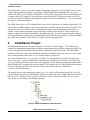
The flow chart for the function Read_button() is shown in Figure 4. The counter keycount is used to
determine whether the push-button has been in a particular state for long enough for action to be taken. It
is used both for debounce and to determine whether a mode change (normal to ID configuration or ID
configuration to normal) is required. If the state of the button (pressed or not pressed) is different from
what it was the previous time through the loop, the counter is reset and the state remembered in key_last.
If, however, the state of the button is the same, the counter value is compared with the required number for
a debounce time of about 60 ms.
If the counter value is equal and the key is pressed, the data or ID is incremented according to the current
mode. If the count is different from that required for debounce, it is compared with the mode change
requirement.
If it is less, the counter is incremented. If it is, or has now become, equal to the mode change requirement
then the mode is changed to ID configuration mode (if the key is pressed) or to normal mode (if it isn’t).
This arrangement ensures that the mode defaults automatically to normal if the key remains not pressed
for three seconds (the time it takes the counter to reach the mode change number — 224 for the EY16).
LINkits LIN Evaluation Boards, Rev. 2
Freescale Semiconductor
7
Slave Software
LIN WAKE-UP SWITCHES MCU
POWER ON
INITIALIZE CONFIG, PORTS, TBM, ICG,
AND LIN DRIVERS. ENABLE INTERRUPTS
NO
TBM FLAG SET
?
YES
CLEAR TBM FLAG
CHECK LIN BUS STATUS
ENTER SLEEP MODE BY PUTTING
THE REGULATOR INTO
STANDBY MODE VIA THE MC33399
(MCU IS SWITCHED OFF)
YES
INACTIVE FOR 5 s
?
NO
INCREMENT COUNT, TOGGLE “TICK”
READ PUSH-BUTTON SWITCH AND
TAKE APPROPRIATE ACTION (FIGURE 4)
WRITE DATA TO LEDS
NO
ID MODE
?
YES
COUNT BIT 4 HIGH
?
NO
ALL LEDS OFF
YES
WRITE ID TO LEDS
ADD RESPOND FIELD TO THE LIN
MESSAGE WITH SELECTED ID
Figure 3. MC68HC908EY16 Slave Software Main Flow Chart
LINkits LIN Evaluation Boards, Rev. 2
8
Freescale Semiconductor
Slave Software
READ PUSH-BUTTON
SAME
?
NO
RESET COUNTER AND
SAVE BUTTON STATUS
YES
DEBOUNCED
?
NO
YES
PUSH-BUTTON PRESSED
?
< MODECOUNT
?
NO
YES
NO
YES
NO
ID MODE
?
YES
INCREMENT DATA
INCREMENT ID
NO
DATA = 16
?
YES
ID = 4
?
NO
YES
DATA = 1
ID = 0
INCREMENT KEYCOUNT COUNTER
MODECOUNT
?
NO
YES
PUSH-BUTTON PRESSED
?
NO
BACK TO NORMAL MODE
YES
ID CONFIGURATION MODE
Figure 4. MC68HC908EY16 Slave Software Push-Button Flow Chart
The function LED_display() writes the required data to the four I/O lines connected to the LEDs, ensuring
that no change is made to any of the other bits on the same port. The data sent is the 4-bit variable data, or
the 2-bit variable ID, according to the current mode. The ID is not displayed in binary so the variable ID
is used to shift a single 1 to the appropriate position. To distinguish the ID display, this LED flashes at
about 2 Hz using the counter count.
LINkits LIN Evaluation Boards, Rev. 2
Freescale Semiconductor
9
CodeWarrior Project
The function LIN_response() uses the variable ID so that the appropriate LIN_PutMsg(ID, data) is active.
In order that the others are inactive, LIN_SEND_UPDATED should be specified in file slave.id (e.g.
#define LIN_MSG_20 LIN_SEND_UPDATED). If LIN_SEND is used, the LIN drivers will always send
a response after LIN_PutMsg(ID, data) has been executed for that ID. This does not apply to the QY4
because it uses the file LINmsg.c instead and the “type of send” can be defined there — see user’s manual
in <st-blue><st-bold>References.
The GR60 doesn’t have an ICG to initialize but its slave code is otherwise very similar to that of the EY16.
The QY4 has no TBM module so it uses the main timer’s overflow flag to pace its loop. This MCU also
doesn’t have an SCI; its LIN interface is implemented using I/O pins in conjunction with the timer’s
channel 1 input capture and output compare interrupts. For this reason, the QY4’s timer counter and
modulus registers should not be modified by the application code. To avoid compromising the timing of
LIN communications, no interrupts, other than those from the LIN drivers themselves, are allowed. Within
these limitations, channel 2 of the timer is available for use by the application.
6
CodeWarrior Project
The demonstration project is structured as shown in <st-blue><st-bold>Figure 5.. The folder sample
contains the demonstration application code that is programmed into the LINkits evaluation boards. This
is where any application being developed with the evaluation boards should reside. The other folders
contain the LIN driver code, which should not normally be modified by the user. Its source code, include
files, and user manual reside in the src, inc, and man folders, respectively.
The vector definition file vector.c is in the hc08 folder. The sample directory contains the application
source code, slave.c, and two additional files that determine the behavior of the slave node. The first is
slave.cfg, which specifies the SCI prescaler value appropriate for the frequency being used and the number
that determines the 5-second no-bus-activity timeout. The second is slave.id, which defines the messages
to be acted upon by this node. The use of these files is described in the user’s manual (see
<st-blue><st-bold>References).
The sample directory also contains the projects .prm, .mcp, and .ini files and an include file slave.h for
register definitions not already defined by the LIN drivers. Again, the QY4 is slightly different. It does not
have the vector.c file but uses its .prm file to define the vectors. It also does not have the slave.cfg or
slave.id file; it uses LINmsg.c for defining messages.
Figure 5. LINkits CodeWarrior Project Structure
LINkits LIN Evaluation Boards, Rev. 2
10
Freescale Semiconductor
References
7
References
AN2503/D: Slave LIN Driver for MC68HC08Q Family
LIN Protocol Specification, Version 1.3, 12 December 2002.
LIN Driver User’s Manual.
9S12C32DGV1/D: MC68HC9S12C32 Device Guide
MC68HC908GZ60/D: MC68HC908GZ60 Technical Data
MC68HC908GR60/D: MC68HC908GR60 Technical Data
MC68HC908EY16/D: MC68HC908EY16 Technical Data
MC68HC908QY4/D: MC68HC908QY4 Technical Data
8
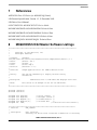
MC68HC9S12C32 Master Software Listings
/******************************************************************************
*
*
Copyright (C) 2003 Motorola, Inc.
*
All Rights Reserved
*
* Filename:
$RCSfile:
/net/sdt/vault-rte/cvsroot/lin/release/hc12star/sample/master/master.c,v $
* Author:
$Author: snl $
* Locker:
$Locker: $
* State:
$State: Exp $
* Revision:
$Revision: 1.2 $
*
* Functions:
Sample application for S12 LINKits Master Driver.
*
* History:
Use the RCS command log to display revision history
*
information.
*
* Description:
Communicates with 16 LIN nodes and displays their data.
*
* Notes:
Also serves as an example of use for the LIN driver.
*
******************************************************************************/
#include <linapi.h>
#include "master.h"
unsigned
unsigned
unsigned
unsigned
unsigned
char
char
char
char
int
ErrCount;
MsgCount;
MsgSent [2];
MsgRcvd [4];
Time;
/*
/*
/*
/*
errors counter
messages counter
transmited data
received deta
/*
*/
*/
*/
*/
time from real time counter */
/*****************************************************************************
* Function:
LIN_Command
*
* Description:
User call-back.
*
Called by the driver after successful transmission or receiving
LINkits LIN Evaluation Boards, Rev. 2
Freescale Semiconductor
11
MC68HC9S12C32 Master Software Listings
*
of the Master Request Command Frame (ID Field value '0x3C').
*
* Returns:
never return
*
* Notes:
*
*****************************************************************************/
void LIN_Command()
{
while(1)
{
}
}
/*****************************************************************************
* Function:
Delay
*
* Description:
Initialise RTI for use in Delay() function
*
*
* Returns:
none
*
* Notes:
busfreq indicates the bus operating frequency in KHz
*
*
*****************************************************************************/
void InitDelay(unsigned int busfreq)
{
switch (busfreq)
{
case 40000: RTICTL = 0x44;
break;
case 32000: RTICTL = 0x60;
break;
case 16000: RTICTL = 0x50;
break;
case 12000: RTICTL = 0x32;
break;
case 8000: RTICTL = 0x40;
break;
case 4915: RTICTL = 0x14;
break;
case 4000: RTICTL = 0x30;
break;
default: break;
}
/* Initialise RTI interrupt */
CRGINT = 0x80;
}
/*****************************************************************************
* Function:
RTI_ISR
*
* Description:
Handle RTI ISR
*
Add one tick to time
*
LINkits LIN Evaluation Boards, Rev. 2
12
Freescale Semiconductor
MC68HC9S12C32 Master Software Listings
* Returns:
none
*
* Notes:
*
*
*****************************************************************************/
#pragma TRAP_PROC
void RTI_ISR( void )
{
Time++;
/* Clear RTI flag */
CRGFLG = 0x80;
}
/*****************************************************************************
* Function:
Delay
*
* Description:
Simple delay routine.
*
Delay for n ms
*
* Returns:
after n ms
*
* Notes:
Uses real time interrupt function - must be initialised
*
elsewhere to give 1ms timeouts
*
*****************************************************************************/
void Delay(unsigned int n)
{
unsigned int stopTime;
stopTime = Time+n;
while (stopTime != Time);
}
/*****************************************************************************
* Function:
NewNode
*
* Description:
Flash LEDs in sequence low to high.
*
* Returns:
none
*
* Notes:
*
*****************************************************************************/
void NewNode()
{
char i;
unsigned char strip = 0x01;
for (i = 0; i < 8; i++)
{
PORTB = ~strip;
Delay(125);
strip = strip<<1;
LINkits LIN Evaluation Boards, Rev. 2
Freescale Semiconductor
13
MC68HC9S12C32 Master Software Listings
}
}
/*****************************************************************************
* Function:
LostNode
*
* Description:
Flash LEDs in sequence high to low.
*
* Returns:
none
*
* Notes:
*
*****************************************************************************/
void LostNode()
{
char i;
unsigned char strip = 0x80;
for (i = 0; i < 8; i++)
{
PORTB = ~strip;
Delay(125);
strip = strip>>1;
}
}
/*****************************************************************************
* Function:
LINActive
*
* Description:
Returns only if master switch has enabled LIN
*
* Returns:
none
*
* Notes:
Flashes LEDs if LIN is disabled
*
*****************************************************************************/
void LINActive()
{
/* Check switch position */
PERJ = 0x40;
while ((PTJ & 0x40) == 0)
{
NewNode();
LostNode();
}
/* Enable LIN interface */
PERJ = 0x80;
}
/*****************************************************************************
* Function:
main
*
* Description:
Sends and receives 2 bytes messages periodically
*
* Returns:
never return
*
* Notes:
LINkits LIN Evaluation Boards, Rev. 2
14
Freescale Semiconductor
MC68HC9S12C32 Master Software Listings
*
*****************************************************************************/
void main( void )
{
int
i,nodeId;
unsigned char
statusDisplay;
LINStatusType
ret;
unsigned char idList[16] = {0x10, 0x11, 0x12, 0x13, 0x18, 0x19, 0x1A, 0x1B, 0x20, 0x21,
0x22, 0x23, 0x28, 0x29, 0x2A, 0x2B};
char activeList[16] = {0,0,0,0,0,0,0,0,0,0,0,0,0,0,0,0};
char messageList = 16;
Time = 0;
/* Initialize driver */
LIN_Init();
/* Enable LED display */
PORTB = 0xFF;
DDRB = 0xFF;
/* Initialise RTI */
InitDelay(16000);
/* Enable interrupt */
#if defined (CW12)
asm cli;
#endif /* defined (CW12) */
#if defined (COSMIC12)
_asm("cli");
#endif /* defined (COSMIC12) */
/* Check/Enable LIN interface */
LINActive();
/* Test message for comms debug */
MsgSent[0] = 0x55;
MsgSent[1] = 0xAA;
/* Update message */
ret = LIN_PutMsg( 0x17, MsgSent );
/* Send a request for message */
ret = LIN_RequestMsg( 0x17 );
/* Wait for message processing */
do
{
ret = LIN_DriverStatus();
}
while( ret & LIN_STATUS_PENDING );
/* Check sent message status */
ret = LIN_MsgStatus( 0x17 );
if ( ret != LIN_OK )
LINkits LIN Evaluation Boards, Rev. 2
Freescale Semiconductor
15
MC68HC9S12C32 Master Software Listings
{
ErrCount = 1;
while(1)
{
}
}
/* Schedule Loop */
while( 1 )
{
/* Check/Enable LIN interface */
LINActive();
/* Slave received messages - cycle here */
for (i = 0; i < messageList; i++)
{
/* Send a request for message */
ret = LIN_RequestMsg( idList[i] );
/* Wait for message processing */
do
{
ret = LIN_DriverStatus();
}
while( ret & LIN_STATUS_PENDING );
/* Check received message status */
ret = LIN_MsgStatus( idList[i] );
if ( ret == LIN_OK )
{
/* Read message */
ret = LIN_GetMsg( idList[i], MsgRcvd );
/* Was message found last time? */
if (activeList[i] == 0)
{
/* No so new Id was added */
activeList[i] = 1;
/*Flash LEDs to indicate new node */
NewNode();
}
MsgCount++;
statusDisplay = MsgRcvd[0] & 0x0F;
nodeId = i*16;
statusDisplay = statusDisplay + nodeId;
PORTB = ~statusDisplay;
Delay(480);
}
else
{
/* Id not found */
/* Was message found last time? */
if (activeList[i] == 1)
{
LINkits LIN Evaluation Boards, Rev. 2
16
Freescale Semiconductor
MC68HC9S12C32 Master Software Listings
/* Yes so Id was lost */
/*Flash LEDs to indicate lost node */
LostNode();
}
activeList[i] = 0;
}
}
}
/* while (1) */
}
/* main */
Appendix A Master.h
/******************************************************************************
*
*
Copyright (C) 2003 Motorola, Inc.
*
All Rights Reserved
*
* Filename:
$RCSfile:
/net/sdt/vault-rte/cvsroot/lin/release/hc12star/sample/master/master.c,v $
* Author:
$Author: snl $
* Locker:
$Locker: $
* State:
$State: Exp $
* Revision:
$Revision: 1.2 $
*
* Functions:
Sample application for S12 LINKits Master Driver.
*
* History:
Use the RCS command log to display revision history
*
information.
*
* Description: Header file for master.c.
*
* Notes:
Also serves as an example of use for the LIN driver.
*
******************************************************************************/
void
void
void
void
void
Delay(unsigned int n);
LostNode();
NewNode();
RTI_ISR();
InitDelay(unsigned int busfreq);
#define
#define
IOBYTE(address)
IOWORD(address)
/* Registers undefined
#define
PORTA
#define
PORTB
#define
DDRA
#define
DDRB
#define
CRGFLG
#define
CRGINT
#define
RTICTL
#define
PTJ
#define
PERJ
(*(( volatile unsigned char*) (address)))
(*(( volatile unsigned int*) (address)))
in standard LIN drivers */
IOBYTE(0x1000)
/* PORTA moved */
IOBYTE(0x1001)
/* PORTB moved */
IOBYTE(0x1002)
/* DDRA moved */
IOBYTE(0x1003)
/* DDRB moved */
IOBYTE(0x1037)
/* CRGFLG moved */
IOBYTE(0x1038)
/* CRGINT moved */
IOBYTE(0x103B)
/* RTICTL moved */
IOBYTE(0x1268)
/* PTJ moved */
IOBYTE(0x126C)
/* PERJ moved */
LINkits LIN Evaluation Boards, Rev. 2
Freescale Semiconductor
17
MC68HC9S12C32 Master Software Listings
Appendix B Master.id
#ifndef LINMSGID_H
#define LINMSGID_H
/******************************************************************************
*
*
Copyright (C) 2003 Motorola, Inc.
*
All Rights Reserved
*
* Filename:
$RCSfile:
/net/sdt/vault-rte/cvsroot/lin/release/hc12star/sample/master/master.id,v $
* Author:
$Author: kam $
* Locker:
$Locker: $
* State:
$State: Exp $
* Revision:
$Revision: 1.3 $
*
* Functions:
Message Identifier configuration for LINS12 LINkits Master sample
*
*
* History:
Use the RCS command log to display revision history
*
information.
*
* Description:
*
* Notes:
*
******************************************************************************/
#define LIN_MSG_17
LIN_SEND
/* EY16
#define
#define
#define
#define
Slave IDs */
LIN_MSG_21 LIN_RECEIVE
LIN_MSG_22 LIN_RECEIVE
LIN_MSG_23 LIN_RECEIVE
LIN_MSG_20 LIN_RECEIVE
/* GR60
#define
#define
#define
#define
Slave IDs */
LIN_MSG_29 LIN_RECEIVE
LIN_MSG_2A LIN_RECEIVE
LIN_MSG_2B LIN_RECEIVE
LIN_MSG_28 LIN_RECEIVE
/* QY4 Slave IDs */
#define LIN_MSG_19
#define LIN_MSG_1A
#define LIN_MSG_1B
#define LIN_MSG_18
LIN_RECEIVE
LIN_RECEIVE
LIN_RECEIVE
LIN_RECEIVE
/* Reserved Slave IDs */
#define LIN_MSG_11 LIN_RECEIVE
#define LIN_MSG_12 LIN_RECEIVE
#define LIN_MSG_13 LIN_RECEIVE
#define LIN_MSG_10 LIN_RECEIVE
#define LIN_MSG_17_LEN
2
#define LIN_MSG_21_LEN
2
/* standard length */
LINkits LIN Evaluation Boards, Rev. 2
18
Freescale Semiconductor
MC68HC9S12C32 Master Software Listings
#define LIN_MSG_22_LEN
#define LIN_MSG_23_LEN
#define LIN_MSG_20_LEN
2
2
2
#define
#define
#define
#define
LIN_MSG_29_LEN
LIN_MSG_2A_LEN
LIN_MSG_2B_LEN
LIN_MSG_28_LEN
2
2
2
2
#define
#define
#define
#define
LIN_MSG_19_LEN
LIN_MSG_1A_LEN
LIN_MSG_1B_LEN
LIN_MSG_18_LEN
2
2
2
2
#define
#define
#define
#define
LIN_MSG_11_LEN
LIN_MSG_12_LEN
LIN_MSG_13_LEN
LIN_MSG_10_LEN
2
2
2
2
#endif /* defined(LINMSGID_H)*/
Appendix C Master.cfg
#ifndef LINCFG_H
#define LINCFG_H
/******************************************************************************
*
*
Copyright (C) 2003 Motorola, Inc.
*
All Rights Reserved
*
* Filename:
$RCSfile:
/net/sdt/vault-rte/cvsroot/lin/release/hc12star/sample/master/master.cfg,v $
* Author:
$Author: kam $
* Locker:
$Locker: $
* State:
$State: Exp $
* Revision:
$Revision: 1.4 $
*
* Functions:
LIN Driver static configuration file for LINS12 LINKits Master sample
*
*
* History:
Use the RCS command log to display revision history
*
information.
*
* Description: Example file that can be modified by the user.
*
* Notes:
*
******************************************************************************/
/* CPU bus freq = 8 MHz */
/* SCI (LIN) freq = 9.6 Kbit */
/*
This definition set the number of user-defined timer clocks
(LIN_IdleClock service calls), recognized as "no-bus-activity"
condition.
LINkits LIN Evaluation Boards, Rev. 2
Freescale Semiconductor
19
MC68HC9S12C32 Master Software Listings
This number shall not be greater than 0xFFFF.
*/
#define LIN_IDLETIMEOUT
100u
/*
This definition configures the LIN bus baud rate.
This value shall be set according to target MCU
SCI register usage.
MC9S12DP256: the 16-bit value is
masked by 0x1FFF and put into SCI0BD register;
*/
#define LIN_BAUDRATE
52u
/*
This definition configures the timer clock rate.
Only for Master node.
This value shall be set according to target MCU
timer prescaler register usage.
MC9S12DP256: the 8-bit value is
masked by 0x07 and put into TSCR2 register;
*/
#define LIN_TIMERPRESCALER
3u
/*
This definition set the length of one bit transmission
period on the target MCU.
Only for Master node.
Due to 16-bit counters on target MCU this value
shall not be greater than 0xFFFF.
For correct timeouts computation this value
shall have qualificator 'l'.
*/
#define LIN_BITTIME
104ul
#endif /* !define (LINCFG_H) */
Appendix D Vector.c
#define VECTOR_C
/******************************************************************************
*
*
Copyright (C) 2003 Motorola, Inc.
*
All Rights Reserved
*
* Filename:
$RCSfile: vector.c,v $
* Author:
$Author: ttz778 $
* Locker:
$Locker: ttz778 $
* State:
$State: Exp $
* Revision:
$Revision: 1.0 $
*
* Functions:
Vectors table for LINS12 Drivers with Motorola API
*
* History:
Use the RCS command log to display revision history
*
information.
*
* Description: This file contains vectors tables for MC9S12DP256 MCU.
LINkits LIN Evaluation Boards, Rev. 2
20
Freescale Semiconductor
MC68HC9S12C32 Master Software Listings
*
It used for LIN Drivers with Motorola API.
*
The users can add their own vectors into the table,
*
but they should not replace LIN Drivers vectors.
*
* Notes:
Timer Channel 0 vector used for Master driver only.
*
*
The following variables shall be defined
*
(this is controlled by the compiler option, which in turn is
*
to be adjusted in 'makefile' or batch file):
*
C32
*
MASTER or SLAVE
*
******************************************************************************/
extern void LIN_ISR_SCI_Interrupt();
/* SCI interrupt routine
extern void LIN_ISR_Timer0();
/* Timer channel 0 interrupt routine */
extern void LIN_Startup();
extern void RTI_ISR();
/* LIN Startup routine
/* LIN Startup routine
*/
*/
*/
/******************************************************************************
INTERRUPT VECTORS TABLE
User is able to add another ISR into this table instead NULL pointer.
******************************************************************************/
#if !defined(NULL)
#define NULL
(0)
#endif /* !defined(NULL) */
#undef
LIN_VECTF
#if defined(CW12)
#define LIN_VECTF
( void ( *const near )( ) )
#endif /* defined(CW12) */
#if defined(COSMIC12)
#define LIN_VECTF
( void *const )
#endif /* defined(COSMIC12) */
/* Vector table function specifier
*/
/* Vector table function specifier
*/
#if defined(CW12)
#pragma CONST_SEG VECTORS_DATA
#endif /* defined(CW12) */
#if defined(CW12)
void near ( * const near _vectab[] )( ) =
#endif /* defined(CW12) */
#if defined(COSMIC12)
void @near ( * const @near _vectab[] )( ) =
#endif /* defined(COSMIC12) */
/***************************************************************************/
/*
C32
*/
/***************************************************************************/
#if defined(C32)
{
LIN_VECTF NULL,
/* 0xFF80: Reserved
*/
LIN_VECTF NULL,
/* 0xFF82: Reserved
*/
LINkits LIN Evaluation Boards, Rev. 2
Freescale Semiconductor
21
MC68HC9S12C32 Master Software Listings
LIN_VECTF NULL,
LIN_VECTF NULL,
LIN_VECTF NULL,
LIN_VECTF NULL,
LIN_VECTF NULL,
LIN_VECTF NULL,
LIN_VECTF NULL,
LIN_VECTF NULL,
LIN_VECTF NULL,
LIN_VECTF NULL,
LIN_VECTF NULL,
LIN_VECTF NULL,
LIN_VECTF NULL,
LIN_VECTF NULL,
LIN_VECTF NULL,
LIN_VECTF NULL,
LIN_VECTF NULL,
LIN_VECTF NULL,
LIN_VECTF NULL,
LIN_VECTF NULL,
LIN_VECTF NULL,
LIN_VECTF NULL,
LIN_VECTF NULL,
LIN_VECTF NULL,
LIN_VECTF NULL,
LIN_VECTF NULL,
LIN_VECTF NULL,
LIN_VECTF NULL,
LIN_VECTF NULL,
LIN_VECTF NULL,
LIN_VECTF NULL,
LIN_VECTF NULL,
LIN_VECTF NULL,
LIN_VECTF NULL,
LIN_VECTF NULL,
LIN_VECTF NULL,
LIN_VECTF NULL,
LIN_VECTF NULL,
LIN_VECTF NULL,
LIN_VECTF NULL,
LIN_VECTF NULL,
LIN_VECTF LIN_ISR_SCI_Interrupt,
LIN_VECTF NULL,
LIN_VECTF NULL,
LIN_VECTF NULL,
LIN_VECTF NULL,
LIN_VECTF NULL,
LIN_VECTF NULL,
LIN_VECTF NULL,
LIN_VECTF NULL,
LIN_VECTF NULL,
LIN_VECTF NULL,
LIN_VECTF NULL,
#if defined(MASTER)
LIN_VECTF LIN_ISR_Timer0,
#endif /* defined(MASTER) */
#if defined(SLAVE)
/*
/*
/*
/*
/*
/*
/*
/*
/*
/*
/*
/*
/*
/*
/*
/*
/*
/*
/*
/*
/*
/*
/*
/*
/*
/*
/*
/*
/*
/*
/*
/*
/*
/*
/*
/*
/*
/*
/*
/*
/*
/*
/*
/*
/*
/*
/*
/*
/*
/*
/*
/*
/*
0xFF84:
0xFF86:
0xFF88:
0xFF8A:
0xFF8C:
0xFF8E:
0xFF90:
0xFF92:
0xFF94:
0xFF96:
0xFF98:
0xFF9A:
0xFF9C:
0xFF9E:
0xFFA0:
0xFFA2:
0xFFA4:
0xFFA6:
0xFFA8:
0xFFAA:
0xFFAC:
0xFFAE:
0xFFB0:
0xFFB2:
0xFFB4:
0xFFB6:
0xFFB8:
0xFFBA:
0xFFBC:
0xFFBE:
0xFFC0:
0xFFC2:
0xFFC4:
0xFFC6:
0xFFC8:
0xFFCA:
0xFFCC:
0xFFCE:
0xFFD0:
0xFFD2:
0xFFD4:
0xFFD6:
0xFFD8:
0xFFDA:
0xFFDC:
0xFFDE:
0xFFE0:
0xFFE2:
0xFFE4:
0xFFE6:
0xFFE8:
0xFFEA:
0xFFEC:
/* 0xFFEE:
Reserved
Reserved
Reserved
Reserved
PWM Emergency Shutdown
Port P
MSCAN 4 transmit
MSCAN 4 receive
MSCAN 4 errors
MSCAN 4 wake-up
MSCAN 3 transmit
MSCAN 3 receive
MSCAN 3 errors
MSCAN 3 wake-up
MSCAN 2 transmit
MSCAN 2 receive
MSCAN 2 errors
MSCAN 2 wake-up
MSCAN 1 transmit
MSCAN 1 receive
MSCAN 1 errors
MSCAN 1 wake-up
MSCAN 0 transmit
MSCAN 0 receive
MSCAN 0 errors
MSCAN 0 wake-up
FLASH
EEPROM
SPI 2
SPI 1
IIC Bus
DLC
SCME
CRG lock
Pulse acc B overf
Down Counter overf
Port H
Port J
ATD 1
ATD 0
SCI 1
SCI 0
SPI 0
Pulse acc input
Pulse acc A overf
Timer Overflow
Timer Channel 7
Timer Channel 6
Timer Channel 5
Timer Channel 4
Timer Channel 3
Timer Channel 2
Timer Channel 1
*/
*/
*/
*/
*/
*/
*/
*/
*/
*/
*/
*/
*/
*/
*/
*/
*/
*/
*/
*/
*/
*/
*/
*/
*/
*/
*/
*/
*/
*/
*/
*/
*/
*/
*/
*/
*/
*/
*/
*/
*/
*/
*/
*/
*/
*/
*/
*/
*/
*/
*/
*/
*/
Timer Channel 0
*/
LINkits LIN Evaluation Boards, Rev. 2
22
Freescale Semiconductor
MC68HC908EY16 Slave Software Listings
LIN_VECTF NULL,
#endif /* defined(SLAVE) */
LIN_VECTF RTI_ISR,
LIN_VECTF NULL,
LIN_VECTF NULL,
LIN_VECTF NULL,
LIN_VECTF NULL,
LIN_VECTF NULL,
LIN_VECTF NULL,
LIN_VECTF LIN_Startup,
};
/* 0xFFEE:
Timer Channel 0
*/
/*
/*
/*
/*
/*
/*
/*
/*
Real Time Interrupt
IRQ
XIRQ
SWI
instr trap
cop fail
cop clock fail
Reset
*/
*/
*/
*/
*/
*/
*/
*/
0xFFF0:
0xFFF2:
0xFFF4:
0xFFF6:
0xFFF8:
0xFFFA:
0xFFFC:
0xFFFE:
#endif /* defined(C32) */
#if defined(CW12)
#pragma CONST_SEG DEFAULT
#endif /* defined(CW12) */
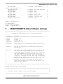
9
MC68HC908EY16 Slave Software Listings
/******************************************************************************
*
*
Copyright (C) 2003 Motorola, Inc. All Rights Reserved
*
* Filename:
$RCSfile:
/net/sdt/vault-rte/cvsroot/lin/release/hc12star/sample/slave/slave.c,v $
* Author:
$Author: snl $
* Locker:
$Locker: $
* State:
$State: Exp $
* Revision:
$Revision: 1.2 $
*
* Functions:
Sample application for LIN08EY16 LINKits Slave Driver
*
* History:
Use the RCS command log to display revision history
*
information.
*
* Function:
Slave supplies a 2-byte response with a selectable ID.
*
The data in the lower nibble of the first byte is the
*
hexadecimal number displayed on the 4 LEDs. This number
*
can be incremented using the button on port A, bit 4.
*
The default ID is $29 with $2A, $2B & $28 selectable
*
using an ID comfiguration mode. This mode is entered by
*
holding the button down for 3 seconds. After this the
*
LEDs flash and display the ID (0:29, 1:2A, 2:2B, 3:28).
*
Pressing the button in this mode increments the ID.
*
After three seconds of no activity on the button, the
*
mode returns to normal.
*
******************************************************************************/
#pragma DATA_SEG SHORT _DATA_ZEROPAGE
/******************************************************************************
*
*
*
Includes, defines, globals and function prototypes
*
*
*
******************************************************************************/
LINkits LIN Evaluation Boards, Rev. 2
Freescale Semiconductor
23
MC68HC908EY16 Slave Software Listings
#include "slave.h"
#include <linapi.h>
#define debounce 4
#define modecount 224
unsigned char data = 1;
unsigned char ID = 0;
unsigned char key_last;
unsigned char count;
unsigned char mode;
unsigned char LIN_data[2];
int keycount;
void Read_button (void);
void LED_display (void);
void LIN_response (void);
/* 13.3ms x (4+1) = 67ms
/* 13.3ms x (224+1) = 3s
*/
*/
/******************************************************************************
*
*
*
Function name: Main
*
*
Originator:
P. Topping
*
*
Date:
18th June 2003
*
*
Function:
Loop at 75Hz. Switch off if no LIN activity for 5s (375). *
*
*
******************************************************************************/
void main (void)
{
CONFIG1 = 0x01;
CONFIG2 = 0x45;
ICGMR = 64;
DDRA = 0x00;
DDRB = 0x3F;
DDRC = 0x80;
PTB = 0x20;
TBCR = 0x20;
TBCR = 0x22;
/*
/*
/*
/*
/*
/*
/*
/*
/*
ICGTR = 158;
asm cli;
LIN_Init();
while (1)
{
if (TBCR & 0x80)
{
TBCR |= 0x08;
LIN_IdleClock ();
if (LIN_DriverStatus () != 0x01)
{
PTB &= ~(0x20);
}
count++;
PTB ^= 0x10;
Read_button ();
LED_display ();
LIN_response ();
dissable COP
slow clock for TBM
ICG nominal 19.6608 MHz
button on A4
LEDS on B0-3, LPI on B5
MCLK on C2 [tick on B4
enable MC33399 LPI
/ by 262144 for 75Hz @
19.661MHz & enable TBM
*/
*/
*/
*/
*/
*/
*/
*/
*/
/* insert trim value here
*/
/* enable interrupts
/* initialise LIN drivers
*/
*/
/* is TBM flag set?
*/
/* yes, clear it
*/
/* check for LIN activity */
/* bus idle for 375 trys ? */
/* yes, power down MCU
*/
/*
/*
/*
/*
/*
*/
*/
*/
*/
*/
used for LED flashing
toggle tick output
read button on PTA4
update LEDs on PTB0-3
send LIN response msg.
LINkits LIN Evaluation Boards, Rev. 2
24
Freescale Semiconductor
MC68HC908EY16 Slave Software Listings
}
}
}
/******************************************************************************
*
*
*
Function name: Read_button
*
*
Originator:
P. Topping
*
*
Date:
19th June 2003
*
*
Function:
The port line is read and its level compared with what
*
*
it was the previous time through the loop. If it is the
*
*
same, the counter "keycount" is used for debounce (80ms) *
*
and to decide if the same state has been present long
*
*
enough (3 seconds) for a mode change. In each mode the
*
*
appropriate increment (data or ID) takes place.
*
*
If the switch status changes the counter is reset.
*
*
*
******************************************************************************/
void Read_button (void)
{
unsigned char key;
key = PTA & 0x10;
if (key == key_last)
{
if (keycount == debounce)
{
if (key == 0)
{
if (mode)
{
ID++;
if (ID == 4) ID = 0;
}
else
{
data++;
if (data == 16) data = 1;
}
}
keycount ++;
}
else if (keycount < modecount)
{
keycount ++;
}
if (keycount == modecount)
{
if (key == 0)
{
mode = 1;
}
else
{
mode = 0;
}
/* read button on A4
/* same as last time ?
*/
*/
/* yes, (debounce + 2)th ? */
/* yes, key pressed ?
*/
/* yes, ID mode ?
*/
/* yes, increment ID
/* wrap round from 3 to 0
*/
*/
/* no, normal mode
*/
/* increment data
/* wrapping from 15 to 1
*/
*/
/* prevents re-entry
*/
/* prevents wraparound
*/
/* time for modechange ?
*/
/* yes, key pressed ?
*/
/* yes, change to ID mode
*/
/* no, not pressed
*/
/* so back to normal mode
*/
LINkits LIN Evaluation Boards, Rev. 2
Freescale Semiconductor
25
MC68HC908EY16 Slave Software Listings
}
}
else
{
keycount = 0;
key_last = key;
/* no, different, so reset */
/* count and save status
*/
}
}
/******************************************************************************
*
*
*
Function name: LED_display
*
*
Originator:
P. Topping
*
*
Date:
19th June 2003
*
*
Function:
According to mode the LEDs display the 4-bit data field
*
*
or the flashing ID (0:21, 1:22, 2:23, 3:20).
*
*
*
******************************************************************************/
void LED_display (void)
{
if (mode)
{
if (count & 0x08)
{
PTB = (PTB & 0xF0) | (1 << ID);
}
else
{
PTB &= 0xF0;
}
}
else
{
PTB = (PTB & 0xF0) | (data & 0x0F);
}
}
/* ID mode LED display
*/
/* ID mode flash, LEDs off */
/* normal mode so
*/
/* drive LEDs with data
*/
/******************************************************************************
*
*
*
Function name: LIN_response
*
*
Originator:
P. Topping
*
*
Date:
19th June 2003
*
*
Function:
According to ID (0:21, 1:22, 2:23, 3:20), a 2-byte
*
*
response field is sent using "data" for the lower nibble *
*
of the first byte. All the other bits are zero.
*
*
*
******************************************************************************/
void LIN_response (void)
{
LIN_data[0] = data;
LIN_data[1] = 0;
switch (ID)
{
case 0:
LINkits LIN Evaluation Boards, Rev. 2
26
Freescale Semiconductor
HC08EY16.h (Register Definitions for the MC68HC908EY16)
LIN_PutMsg (0x21, LIN_data);
break;
/* LIN response to ID21
*/
case 1:
LIN_PutMsg (0x22, LIN_data);
break;
/* LIN response to ID22
*/
case 2:
LIN_PutMsg (0x23, LIN_data);
break;
/* LIN response to ID23
*/
/* LIN response to ID20
*/
case 3:
LIN_PutMsg (0x20, LIN_data);
break;
}
}
/******************************************************************************
* Function:
LIN_Command
* Description:
User call-back. Called by the driver after transmission or
*
reception of the Master Request Command Frame (ID: 0x3C).
******************************************************************************/
void LIN_Command()
{
while(1)
{
}
}
10
HC08EY16.h (Register Definitions for the
MC68HC908EY16)
/******************************************************************************
*
*
Copyright (C) 2003 Motorola, Inc.
*
All Rights Reserved
*
* Filename:
$RCSfile:
/net/sdt/vault-rte/cvsroot/lin/release/hc12star/sample/master/master.c,v $
* Author:
$Author: snl $
* Locker:
$Locker: $
* State:
$State: Exp $
* Revision:
$Revision: 1.2 $
*
* Functions:
Sample application for 08EY16 LINKits Slave Driver.
*
* History:
Use the RCS command log to display revision history
*
information.
*
* Description: Header file for slave.c.
*
* Notes:
Also serves as an example of use for the LIN driver.
*
******************************************************************************/
LINkits LIN Evaluation Boards, Rev. 2
Freescale Semiconductor
27
HC08EY16.h (Register Definitions for the MC68HC908EY16)
void
void
void
void
void
Read_button (void);
LED_display (void);
LIN_response (void);
LIN_Command(void);
Dummy_ISR( void );
#define
#define
IOBYTE(address)
IOWORD(address)
(*(( volatile unsigned char*) (address)))
(*(( volatile unsigned int*) (address)))
/* Registers undefined in standard LIN drivers */
#define
PTA
IOBYTE(0x0000)
/* PORT A */
#define
PTB
IOBYTE(0x0001)
/* PORT B */
#define
PTC
IOBYTE(0x0002)
/* PORT C */
#define
PTD
IOBYTE(0x0003)
/* PORT D */
#define
PTE
IOBYTE(0x0008)
/* PORT E */
#define
#define
#define
#define
#define
DDRA
DDRB
DDRC
DDRD
DDRE
IOBYTE(0x0004)
IOBYTE(0x0005)
IOBYTE(0x0006)
IOBYTE(0x0007)
IOBYTE(0x000A)
#define
#define
SCBR
SCPSC
IOBYTE(0x0016)
IOBYTE(0x0017)
#define
#define
CONFIG1
CONFIG2
IOBYTE(0x001F)
IOBYTE(0x001E)
#define
TBCR
IOBYTE(0x001C)
#define
#define
#define
#define
#define
#define
#define
#define
#define
#define
#define
TASC
TACNTH
TACNTL
TAMODH
TAMODL
TASC0
TACH0H
TACH0L
TASC1
TACH1H
TACH1L
IOBYTE(0x0020)
IOBYTE(0x0021)
IOBYTE(0x0022)
IOBYTE(0x0023)
IOBYTE(0x0024)
IOBYTE(0x0025)
IOBYTE(0x0026)
IOBYTE(0x0027)
IOBYTE(0x0028)
IOBYTE(0x0029)
IOBYTE(0x002A)
#define
#define
#define
#define
#define
#define
#define
#define
#define
#define
#define
TBSC
TBCNTH
TBCNTL
TBMODH
TBMODL
TBSC0
TBCH0H
TBCH0L
TBSC1
TBCH1H
TBCH1L
IOBYTE(0x002B)
IOBYTE(0x002C)
IOBYTE(0x002D)
IOBYTE(0x002E)
IOBYTE(0x002F)
IOBYTE(0x0030)
IOBYTE(0x0031)
IOBYTE(0x0032)
IOBYTE(0x0033)
IOBYTE(0x0034)
IOBYTE(0x0035)
#define ICGCR
#define ICGMR
/*
/*
/*
/*
/*
DDR
DDR
DDR
DDR
DDR
A
B
C
D
E
*/
*/
*/
*/
*/
IOBYTE(0x0036)
IOBYTE(0x0037)
LINkits LIN Evaluation Boards, Rev. 2
28
Freescale Semiconductor
HC08EY16.h (Register Definitions for the MC68HC908EY16)
#define ICGTR
IOBYTE(0x0038)
#define DDIV
#define DSTG
IOBYTE(0x0039)
IOBYTE(0x003A)
Appendix E Slave.id (LIN Message ID File)
#ifndef LINMSGID_H
#define LINMSGID_H
/******************************************************************************
*
*
Copyright (C) 2003 Motorola, Inc.
*
All Rights Reserved
*
* Filename:
$RCSfile:
/net/sdt/vault-rte/cvsroot/lin/release/hc12star/sample/master/master.id,v $
* Author:
$Author: kam $
* Locker:
$Locker: $
* State:
$State: Exp $
* Revision:
$Revision: 1.3 $
*
* Functions:
Message Identifier configuration for LIN08 LINkits Slave sample
*
*
* History:
Use the RCS command log to display revision history
*
information.
*
* Description:
*
* Notes:
*
******************************************************************************/
#define
#define
#define
#define
LIN_MSG_20
LIN_MSG_21
LIN_MSG_22
LIN_MSG_23
LIN_SEND_UPDATED
LIN_SEND_UPDATED
LIN_SEND_UPDATED
LIN_SEND_UPDATED
#define
#define
#define
#define
LIN_MSG_20_LEN
LIN_MSG_21_LEN
LIN_MSG_22_LEN
LIN_MSG_23_LEN
2
2
2
2
/*
/*
/*
/*
non-standard
non-standard
non-standard
non-standard
length
length
length
length
*/
*/
*/
*/
#endif /* defined(LINMSGID_H)*/
Appendix F Slave.cfg (LIN Configuration File)
#ifndef LINCFG_H
#define LINCFG_H
/******************************************************************************
LINkits LIN Evaluation Boards, Rev. 2
Freescale Semiconductor
29
HC08EY16.h (Register Definitions for the MC68HC908EY16)
*
*
Copyright (C) 2003 Motorola, Inc.
*
All Rights Reserved
*
* Filename:
$RCSfile:
/net/sdt/vault-rte/cvsroot/lin/release/hc08/sample/master/master.cfg,v $
* Author:
$Author: kam $
* Locker:
$Locker: $
* State:
$State: Exp $
* Revision:
$Revision: 1.12 $
*
* Functions:
LIN Driver static configuration file for LIN08 LINkitsMaster sample
*
*
* History:
Use the RCS command log to display revision history
*
information.
*
* Description: It is allowed to modify by the user.
*
* Notes:
*
******************************************************************************/
/* External MCU frequency = 8.000MHz
/* SCI Baud rate
= 9600
/*
This definition configures the ESCI Prescaler divide ratio
#define LIN_SCIPRESCALER
/*
/*
/*
/*
*/
*/
0x60u
*/
/* divide by 4
*/
This definition configures the LIN bus baud rate. This value
shall be set according to target MCU SCI register usage.
HC08EY16: the 8-bit SCBR value will be masked by 0x37.
The following numbers assume that the ESCI prescaller = 4
*/
*/
*/
*/
/* Selects 9600 baud for a nominal 2.4576 MHz clock (ICGMR=32)
//#define LIN_BAUDRATE
0x00u
*/
/* Selects 9600 baud for a nominal 4.9152 MHz clock (ICGMR=64)
#define LIN_BAUDRATE
0x01u
*/
/* Enable ESCI (fractional divide prescaler) baudrate synch.
*/
#define LIN_SYNC_SLAVE
/* The following numbers assume that the ESCI prescaller = 1
*/
/* Selects 9600 baud rate if using a 4.9152MHz crystal
//#define LIN_BAUDRATE
0x03u
*/
/* Selects 9600 baud rate if using an 8.000MHz crystal
//#define LIN_BAUDRATE
0x30u
*/
/* Selects 9600 baud rate if using a 16.000MHz crystal
*/
LINkits LIN Evaluation Boards, Rev. 2
30
Freescale Semiconductor
HC08EY16.h (Register Definitions for the MC68HC908EY16)
//#define LIN_BAUDRATE
0x31u
/* Selects 9600 baud rate if using a 32.000MHz crystal
//#define LIN_BAUDRATE
0x32u
/*
*/
This definition sets the number of user-defined time clocks
(LIN_IdleClock service calls), recognized as "no-bus-activity"
condition. This number shall not be greater than 0xFFFF.
*/
#define LIN_IDLETIMEOUT
375u
#endif /* !define (LINCFG_H) */
vector.c
Appendix G #define VECTOR_C
/******************************************************************************
*
*
Copyright (C) 2003 Motorola, Inc.
*
All Rights Reserved
*
* Filename:
RCSfile: \\\\Zuk07fil02\\8_16BitMCU\\Strategic\040Mktg_Sys\\RCS\\
D\\Projects\\CW\\LIN08EY16_src\\hc08\\vector.c,v $
* Author:
$Author: ttz778 $
* Locker:
$Locker: $
* State:
$State: Exp $
* Revision:
$Revision: 1.0 $
*
* Functions:
Vectors table for LIN08EY16 Drivers
*
* History:
Use the RCS command log to display revision history
*
information.
*
* Description: Vector table and node's startup for HC08.
*
The users can add their own vectors into the table,
*
but they should not replace LIN Drivers vectors.
*
* Notes:
1. The only one of the following variables may be defined, while
*
all others are undefined. This is controlled by the compiler
*
option, which in turn is to be adjusted in 'makefile' or batch
*
file:
*
HC08EY16
*
******************************************************************************/
#if defined(HC08EY16)
extern void LIN_ISR_SCI_Receive();
extern void LIN_ISR_SCI_Error();
extern void TimerA0();
extern void TimerA1();
// extern void TimerB();
// extern void BREAK_Command();
#endif /* defined(HC08EY16) */
/*
/*
/*
/*
/*
/*
ESCI receive ISR
ESCI error ISR
Timer Module A Channel 0 ISR
Timer Module A Channel 1 ISR
Timer Module B Overflow ISR
SWI ISR
*/
*/
*/
*/
*/
*/
/******************************************************************************
NODE STARTUP
By default compiler startup routine is called.
User is able to replace this by any other routine.
******************************************************************************/
LINkits LIN Evaluation Boards, Rev. 2
Freescale Semiconductor
31
HC08EY16.h (Register Definitions for the MC68HC908EY16)
#if defined(CW08)
#define Node_Startup
_Startup
extern void _Startup();
#endif /* defined(CW08) */
#if defined(COSMIC08)
#define Node_Startup
_stext
extern void _stext();
#endif /* defined(COSMIC08) */
/* CW08 compiler startup routine declaration */
/* Cosmic compiler startup routine declaration
*/
/******************************************************************************
INTERRUPT VECTORS TABLE
User is able to add another ISR into this table instead NULL pointer.
******************************************************************************/
#if !defined(NULL)
#define NULL
(0)
#endif /* !defined(NULL) */
#undef
LIN_VECTF
#if defined(CW08)
#define LIN_VECTF ( void ( *const ) ( ) )
#pragma CONST_SEG VECTORS_DATA
void (* const _vectab[])( ) =
#endif /* defined(CW08) */
/* vectors segment declaration */
#if defined(COSMIC08)
#define LIN_VECTF (void *const)
void *const _vectab[] =
#endif /* defined(COSMIC08) */
#if defined(HC08EY16)
LINkits LIN Evaluation Boards, Rev. 2
32
Freescale Semiconductor
HC08EY16.h (Register Definitions for the MC68HC908EY16)
/***************************************************************************/
/*
*/
/*
HC08EY16
*/
/*
*/
/*
These vectors are appropriate for the 2L31N mask set of the
*/
/*
MC68HC908EY16 and all subsequent versions.
*/
/*
*/
/*
Older mask sets, e.g. 0L38H, 1L38H, 0L31N and 1L31N had a fault
*/
/*
in their interrupt vector table and hence in the priorities.
*/
/*
For these older mask sets the order of the SCI vectors was:
*/
/*
*/
/*
SCI_Error_ISR,
// 0xFFE6
ESCI error
*/
/*
SCI_Transmit_ISR,
// 0xFFE8
ESCI transmit
*/
/*
SCI_Receive_ISR,
// 0xFFEA
ESCI receive
*/
/*
*/
/*
All other vectors are unchanged.
*/
/*
*/
/***************************************************************************/
{
LIN_VECTF
LIN_VECTF
LIN_VECTF
LIN_VECTF
LIN_VECTF
NULL,
NULL,
NULL,
NULL,
NULL,
/*
/*
/*
/*
/*
#if defined(MASTER)
LIN_VECTF LIN_ISR_SCI_Transmit,
#endif /* defined(MASTER) */
#if defined(SLAVE)
LIN_VECTF NULL,
#endif /* defined(SLAVE) */
LIN_VECTF LIN_ISR_SCI_Receive,
LIN_VECTF LIN_ISR_SCI_Error,
//
LIN_VECTF
LIN_VECTF
LIN_VECTF
LIN_VECTF
LIN_VECTF
LIN_VECTF
LIN_VECTF
LIN_VECTF
LIN_VECTF
LIN_VECTF
LIN_VECTF
NULL,
NULL,
NULL,
NULL,
NULL,
NULL,
NULL,
NULL,
BREAK_Command,
NULL,
Node_Startup
0xFFDC
0xFFDE
0xFFE0
0xFFE2
0xFFE4
Timebase
SPI transmit
SPI receive
ADC
Keyboard
*/
*/
*/
*/
*/
/* (used for Master node only)*/
/* 0xFFE6
ESCI transmit
*/
/* 0xFFE6
ESCI transmit
*/
/* 0xFFE8
/* 0xFFEA
ESCI receive
ESCI error
*/
*/
/*
/*
/*
/*
/*
/*
/*
/*
/*
/*
/*
TIMER B
TIMER B
TIMER B
TIMER A
TIMER A
TIMER A
CMIREQ
IRQ
SWI
SWI
RESET
*/
*/
*/
*/
*/
*/
*/
*/
*/
*/
*/
0xFFEC
0xFFEE
0xFFF0
0xFFF2
0xFFF4
0xFFF6
0xFFF8
0xFFFA
0xFFFC
0xFFFC
0xFFFE
overflow
channel 1
channel 0
overflow
channel 1
channel 0
};
#endif
/* defined(HC08EY16) */
#if defined(CW08)
#pragma CONST_SEG DEFAULT
#endif /* defined(CW08) */
LINkits LIN Evaluation Boards, Rev. 2
Freescale Semiconductor
33
How to Reach Us:
Home Page:
www.freescale.com
E-mail:
[email protected]
USA/Europe or Locations Not Listed:
Freescale Semiconductor
Technical Information Center, CH370
1300 N. Alma School Road
Chandler, Arizona 85224
+1-800-521-6274 or +1-480-768-2130
[email protected]
Europe, Middle East, and Africa:
Freescale Halbleiter Deutschland GmbH
Technical Information Center
Schatzbogen 7
81829 Muenchen, Germany
+44 1296 380 456 (English)
+46 8 52200080 (English)
+49 89 92103 559 (German)
+33 1 69 35 48 48 (French)
[email protected]
Japan:
Freescale Semiconductor Japan Ltd.
Headquarters
ARCO Tower 15F
1-8-1, Shimo-Meguro, Meguro-ku,
Tokyo 153-0064
Japan
0120 191014 or +81 3 5437 9125
[email protected]
Asia/Pacific:
Freescale Semiconductor Hong Kong Ltd.
Technical Information Center
2 Dai King Street
Tai Po Industrial Estate
Tai Po, N.T., Hong Kong
+800 2666 8080
[email protected]
For Literature Requests Only:
Freescale Semiconductor Literature Distribution Center
P.O. Box 5405
Denver, Colorado 80217
1-800-441-2447 or 303-675-2140
Fax: 303-675-2150
[email protected]
Document Number: AN2573
Rev. 2
01/2007
Information in this document is provided solely to enable system and software
implementers to use Freescale Semiconductor products. There are no express or
implied copyright licenses granted hereunder to design or fabricate any integrated
circuits or integrated circuits based on the information in this document.
Freescale Semiconductor reserves the right to make changes without further notice to
any products herein. Freescale Semiconductor makes no warranty, representation or
guarantee regarding the suitability of its products for any particular purpose, nor does
Freescale Semiconductor assume any liability arising out of the application or use of any
product or circuit, and specifically disclaims any and all liability, including without
limitation consequential or incidental damages. “Typical” parameters that may be
provided in Freescale Semiconductor data sheets and/or specifications can and do vary
in different applications and actual performance may vary over time. All operating
parameters, including “Typicals”, must be validated for each customer application by
customer’s technical experts. Freescale Semiconductor does not convey any license
under its patent rights nor the rights of others. Freescale Semiconductor products are
not designed, intended, or authorized for use as components in systems intended for
surgical implant into the body, or other applications intended to support or sustain life,
or for any other application in which the failure of the Freescale Semiconductor product
could create a situation where personal injury or death may occur. Should Buyer
purchase or use Freescale Semiconductor products for any such unintended or
unauthorized application, Buyer shall indemnify and hold Freescale Semiconductor and
its officers, employees, subsidiaries, affiliates, and distributors harmless against all
claims, costs, damages, and expenses, and reasonable attorney fees arising out of,
directly or indirectly, any claim of personal injury or death associated with such
unintended or unauthorized use, even if such claim alleges that Freescale
Semiconductor was negligent regarding the design or manufacture of the part.
Freescale™ and the Freescale logo are trademarks of Freescale Semiconductor, Inc.
All other product or service names are the property of their respective owners.
© Freescale Semiconductor, Inc. 2006. All rights reserved.
RoHS-compliant and/or Pb-free versions of Freescale products have the functionality
and electrical characteristics as their non-RoHS-compliant and/or non-Pb-free
counterparts. For further information, see http://www.freescale.com or contact your
Freescale sales representative.
For information on Freescale’s Environmental Products program, go to
http://www.freescale.com/epp.