1
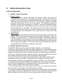
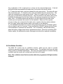
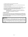
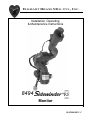
ELKHART BRASS MFG. CO., INC.
1302 WEST BEARDSLEY AVENUE • P.O. BOX 1127 • ELKHART IN 46515 • (574) 295-8330 • FAX (574) 293-9914
Installation, Operating,
& Maintenance Instructions
8494
Monitor
98429000 REV. C
SYSTEM INFORMATION:
MONITOR SERIAL NUMBER: ___________________________________________
MONITOR ACCESSORIES (NOZZLE GALLONAGE AND TYPE, TYPES OF TRANSMITTERS,
WATER VALVE (Y/N), ETC.):
_______________________________________________________________
_______________________________________________________________
_______________________________________________________________
_______________________________________________________________
_______________________________________________________________
_______________________________________________________________
_______________________________________________________________
_______________________________________________________________
TABLE OF CONTENTS
I.
PRODUCT SAFETY ...................................................................................................1
II.
SYSTEM COMPONENT DESCRIPTIONS ....................................................................3
A.
B.
C.
RF Monitor.................................................................................................. 3
RF Receiver/Control Module ............................................................................................... 3
RF Transmitters..................................................................................................................... 4
1. Primary Transmitter .......................................................................................................... 5
2. Secondary Hand Held Transmitter ................................................................................. 6
D.
5000 Series Nozzles............................................................................................................. 6
E.
81181501 Water Valve Kit (Optional) ................................................................................ 7
F.
SM-10FE De/Anti-Icing Nozzle ........................................................................................... 7
III.
CONTROL SYSTEM SPECIFICATIONS .......................................................................8
IV.
INSTALLATION INSTRUCTIONS .................................................................................9
A.
1.
2.
3.
4.
B.
C.
V.
Component Mounting ........................................................................................................... 9
RF Monitor .................................................................................................. 9
RF Receiver/Control Module Wiring ............................................................................ 10
Joystick Control Box ....................................................................................................... 11
81181501 Water Valve Kit (Optional) .......................................................................... 11
RF Settings .......................................................................................................................... 13
Left/Right Rotation Envelope Programming ................................................................... 14
OPERATING INSTRUCTIONS ...................................................................................16
A.
1.
2.
B.
C.
VI.
Normal Operation................................................................................................................ 16
81498001 Joystick Transmitter ..................................................................................... 16
81502001 Handheld Transmitter .................................................................................. 16
Oscillation Function ............................................................................................................ 17
Manual Override.................................................................................................................. 18
MAINTENANCE .......................................................................................................19
A.
B.
C.
Preventive Maintenance .................................................................................................... 19
Understanding the RF Receiver/Control Module Circuit Board LEDs ........................ 19
Handheld Transmitter ......................................................................................................... 20
1. Battery Type..................................................................................................................... 20
2. Replacing the Batteries .................................................................................................. 20
VII.
MONITOR & NOZZLE HYDRAULIC DATA ................................................................21
VIII.
PARTS DRAWINGS..............................................................................................24
I.
PRODUCT SAFETY
Important:
Before installing and operating this equipment, read & study this manual thoroughly.
Proper installation is essential to safe operation. In addition, the following points
should be adhered to in order to ensure the safety of equipment and personnel:
1. All personnel who may be expected to use this equipment must be
thoroughly trained in its safe and proper use.
2. Before flowing water from this device, check that all personnel (fire
service and civilian) are out of the stream path. Also, check to make
sure stream direction will not cause avoidable property damage.
3. Become thoroughly familiar with the hydraulic characteristics of this
equipment, and the pumping system used to supply it. To produce
effective fire streams, operating personnel must be properly trained.
4. Whenever possible, this equipment should be operated from a remote
location. Do not needlessly expose personnel to dangerous fire
conditions.
5. Open water valve supplying this equipment slowly, so that the piping
fills slowly, thus preventing possible water hammer occurrence.
6. After each use, and on a scheduled basis, inspect equipment per
instructions in section VI.
7. Any modifications to the electrical enclosures will destroy the NEMA 4
rating and void warranty coverage of the enclosure and all components
within.
Page 1
Figure 1
8494
Monitor
Page 2
II.
A.
SYSTEM COMPONENT DESCRIPTIONS
RF Monitor
The
RF Monitor is specially designed for use on off-road or wild land fire
RF is controlled from inside the cab through a wireless
fighting apparatus. The
transmitter or by handheld transmitter so risk to firefighters is significantly reduced.
The
RF features durable Elk-O-Lite® construction combined with rugged,
stainless steel gears and motors that are completely enclosed and sealed for maximum
protection from the elements. The
RF has a flow efficient 2.0” vaned waterway
to minimize turbulence and provide superior fire streams. Water supply is provided through
the monitor base by 2” National Pipe Thread connection. The discharge nozzle connection is
a 1½” National Hose Thread. Nozzle stream direction is controlled by two permanent
magnet type gear motors, one controlling rotation about the axis of the water inlet, and the
other controlling nozzle elevation and depression.
An optional 2.0” electric valve kit is available to allow the user to control water flow directly
from the
RF control box. This enables “pump and roll” functionality with
complete control by the operator in the cab of the truck via wireless joystick control. The
electric valve can also be controlled using the optional handheld wireless transmitter.
B. RF Receiver/Control Module
The monitor control circuit uses a state-of-the-art PIC (Programmable Integrated Circuit) chip
design. This device allows numerous control features while keeping circuit board size to a
minimum. Relays within this box provide motor reversing control for the Up/Down, Left/Right,
valve Open/Close and nozzle Straight Stream/Fog functions.
All functions are sent to the RF receiver/control module via an encoded radio frequency link.
The radio link reduces the number of control wires down to just the two power leads,
dramatically simplifying the installation procedure. The link also allows wireless control from
up to ¼ mile away using a battery powered handheld transmitter.
A rotary pulse counter, part of the horizontal motor, provides horizontal motion control
feedback. The counter in combination with the PIC controller enables the monitor to move
between programmable endpoints that are programmed by the user for rotation up to
360°total (+/- 180° from center). This feature also allows the unit to be programmed to
oscillate between positions within the total travel setting. This feature can be programmed
easily with any of the wireless transmitters. No mechanical stops to adjust.
The control circuit also provides secondary motor protection with the use of electronic current
sensing circuitry. If the monitor encounters an obstruction before reaching a pre-set limit,
this circuitry quickly senses motor stall current and automatically shuts off power to the
motor. As soon as the control switch is released, the circuit resets to allow subsequent
operation of the monitor.
Page 3
Figure 2
81496001 RF Receiver/Control Module
Caution:
Any modification of the enclosure will destroy the NEMA 4 rating, and will void the warranty
coverage of the RF Receiver/Control Module.
The following additional functions/features are provided in the RF receiver/control module:
Reverse Polarity Protection: If battery connections are reversed, this feature
prevents power from being applied to circuits, and prevents damage to
electronic components.
Circuit Board Moisture Protection: In addition to being protected within a
NEMA 4 sealed enclosure, the circuit board and circuit components are
protected from moisture by an acrylic resin conformal coating.
C. RF Transmitters
The 8494 RF monitor uses W.E.T. (Wireless Electronic Technology), an innovative wireless
radio link, to send all commands from the RF transmitters to the RF Receiver/Control
Module. The new W.E.T. wireless link gives the operator the ability to view the discharge
stream and target from virtually any point of view. The 8494-RF monitor comes standard
with a joystick or a twin joystick transmitter. An optional handheld transmitter can be
purchased from Elkhart Brass and can be programmed to work with any W.E.T. enabled
monitor.
Page 4
1.
Primary Transmitter
The Sidewinder RF has two joystick transmitter options. Either joystick transmitter can be
used and will override the handheld transmitter.
81498001 Joystick Transmitter
(Figure 3) The RF joystick is suitable for
mounting inside the apparatus cab. The joystick
controls all four monitor functions plus
oscillation. Up/Down and Left/Right monitor
functions can be operated simultaneously. The
water valve is controlled with a trigger switch on
the front of the joystick. The water valve can
also be locked open by activating the button
located on the enclosure top. Nozzle pattern is
changed using the rocker switch on the top of
the joystick. The monitor direction is changed by
moving the joystick in the desired direction.
Oscillation is programmed by using the joystick
in conjunction with the oscillate button.
Figure 3
81498001 Joystick Transmitter
Caution: Joysticks are not environmentally sealed.
only. Use outside of cab will void the warranty coverage.
Page 5
They are meant for in cab use
2.
Secondary Hand Held Transmitter
81502001 Handheld Transmitter
(Figure 4) A sealed handheld remote contains all the controls
necessary for operation of the monitor, oscillation, nozzle, and
water valve. The handheld remote allows the operator to
direct the monitor from a significantly improved point of view.
With the wireless remote, the operator can view the stream
from the side and confirm it is hitting the target. Separate
push button switches are provided for up, down, left, right, fog,
stream, valve open, and valve close functions. The handheld
remote has user selectable frequency and security codes that
allow multiple monitors to operate on the same fire ground at
the same time. The remote has an automatic power down
feature that will shut down the power after 5 minutes of no
activity. As an additional power saving feature, the radio
signal is only transmitted while a button is pushed. The
handheld remote case has a NEMA 4 rating.
Figure 4
81502001 Handheld Transmitter
Caution: Any modification of the enclosure of the handheld transmitter will destroy
the NEMA 4 rating, and will void the warranty coverage of the remote control.
D. 5000 Series Nozzles
Three constant flow electric nozzles are offered with the
RF monitor with flows ranging from 15
to 350 GPM. The nozzle pattern is electrically actuated
and controlled by the monitor control box. The 5000-04
Series nozzles have a flush feature to clear debris from
the nozzle without shutting down the water flow.
5000-04; 15, 30, or 45 GPM
5000-14; 60, 95, 125, or 150 GPM
5000-24; 175, 200, 250, or 350 GPM
Figure 5
5000-24 Electrically Actuated Nozzle
Page 6
E. 81181501 Water Valve Kit (Optional)
The
RF water valve kit provides a
convenient remote on-off control of the water
supply to the 8494
RF. This allows
the operator complete control of the unit from the
safety of the vehicle cab or radio handheld
transmitter. The water valve motor speed
prevents water hammer, yet closes quickly
enough to help preserve the limited on-board
water supply.
Figure 6
2920E Electrically Actuated Valve
F. SM-10FE De/Anti-Icing Nozzle
Designed for the aircraft deicing industry, this nozzle has
been designed for use with type 1 de-icing, type 2 antiicing, or type 4 anti-icing fluids. The SM-10FE has Viton®
O-rings to withstand the use of the Ethylene Glycol and
Propylene Glycol solutions used to de-ice aircraft. The
nozzle is constant gallonage at pressures below 90 Psi
and becomes automatic at 95 Psi. It is designed to deliver
20 GPM at 50 Psi and 30 –120 GPM from 90-110 Psi.
Figure 7
SM-10FE De/Anti-Icing Nozzle
Page 7
III. CONTROL SYSTEM SPECIFICATIONS
Handheld Transmitter Specifications
•
•
Input power
Output power
•
•
•
•
Transmitter dimensions
Transmitter weight
Operating temperature range
FCC ID
2 AA batteries (Alkaline recommended)
Meets FCC part 15 requirements for license free
operation
6” x 3 1/4” x 1 3/8”
10 ½ oz.
-40°F to 150°F (-40°C to 65°C)
QT8PTSS2003
Fixed Transmitter Specifications
•
•
Input power
Output power
•
•
•
Transmitter dimensions
Operating temperature range
FCC ID
12/24 VDC (11VDC to 27 VDC)
Meets FCC part 15 requirements for license free
operation
Joystick:
4 3/4” x 4 11/16” x 10 5/8”
-40°F to 150°F (-40°C to 65°C)
QT8PTSS2003
RF Receiver/Control Module Specifications
•
•
•
•
12VDC (11VDC to 14VDC)
16 1/4” x 10 1/2” x 3 3/16”
0.15 A*
-40°F to 176°F (-40°C to 80°C)
Power requirements
RF Receiver/Control Module dimensions
Control current
Operating temperature range
Table 1
Motor Current Specifications
Monitor
Run I
Stall I
Current Trip Point
Left/Right
2A
12 A
9.2 A
Up/Down
2A
14 A
8A
Nozzle
0.5 A
NA
4A
Shock:
•
30 G's (55 Hz. @ .2 inch double amplitude)
Vibration:
•
15.5 G's (55 Hz. @ .05 inch double amplitude) continuous operation
Drop Test:
•
Both the transmitter and RF receiver/control module must meet operating specifications after drop from
1-meter height onto concrete surface.
Environmental:
•
*
NEMA 4 rating (except 81498001 Joystick Assembly) (must withstand a 1 inch stream of water (65
gpm) from a distance of ten feet for five minutes, with no water entering the enclosure).
All current ratings are at 12 volts
Page 8
IV. INSTALLATION INSTRUCTIONS
A. Component Mounting
1.
RF Monitor
RF monitor, ensure that both the horizontal and vertical
Before mounting the
rotation envelopes are clear of all obstructions. See
Figure 8 and Figure
9 for envelope dimensions. The left-right rotation limits are programmable. [They are factory
set at 180° (+/- 90° from zero position)].
Caution: Using the manual override feature will alter the programmed travel limits
when used when the left-right motor is not powered. This could cause possible damage to
the vehicle or monitor unit.
1) Ensure the left-right and up-down motors are aligned as shown in
Figure 8. This is zero position.
2) Ensure that all of the electrical connections have been disconnected.
3) Tighten the Sidewinder® RF monitor to a securely mounted 2.0” NPT (additional
support may be necessary). The monitor can be mounted in any orientation, although
some orientations will reverse the directions of movement relative to the function labeling
on the transmitter(s). Apply a suitable thread sealant, thread the monitor onto the pipe
connection, and tighten it securely with a strap wrench. Do not use motors or discharge
as a lever to tighten monitor. Make sure the motor on the monitor base is facing away
from the intended center of rotation. Harness will not allow monitor to rotate more than
180° from zero position for a total 360° rotation.
4) Reconnect the electrical connections according to Figure 12. Check all of the
electrical connections to make sure they are tight. Allow enough slack in the monitor
harness to permit travel to the limits allowed by the RF Receiver/Control Module without
straining the wires.
Warning:
The harness is not designed for continuous 360° rotation. The monitor
will travel more than 360° if travel limits are not programmed. Be sure travel limits are
programmed to prevent damage from over traveling.
ZERO
POSITION
90
O
FACTORY
SETTING
90
O
90
O
FACTORY
SETTING
R12.63
45
O
180 MAX
O
180 MAX
O
Figure 8
Programmable Left-Right Rotation Envelope
Page 9
Figure 9
Up-Down Rotation Envelope
2. RF Receiver/Control Module Wiring
1) Place a 10A fuse between the red lead of the RF Receiver/Control Module power
connector and a switched positive power lead on the vehicle. Attach the black lead from
the RF Receiver/Control Module power connector to the vehicle ground.
2) All control functions are sent to the monitor via an encoded RF signal from the
transmitter; no control wiring is needed.
3) Mark the mounting screw pattern per dimensions in Figure 10.
4) Drill four ∅0.203” (13/64” drill) holes.
5) Secure the unit to the panel with four #10-32 screws with nuts and lock washers (not
supplied). The length of the screws should be the panel thickness plus 3/8” minimum.
Figure 10
81496001 RF Receiver/Control Module Mounting Layout
Page 10
Figure 11
81498001 Joystick Transmitter Mounting Layout
3. Joystick Control Box
1) Mark the mounting screw pattern per dimensions in Figure 11.
2) Drill four ∅0.203” (13/64” drill) holes.
3) Secure the unit to the panel with four #10-32 screws with nuts and lock washers (not
supplied). The length of the screws should be the panel thickness plus 3/8” minimum.
4) Place a 1A fuse between the red lead of the transmitter and a switched positive power
lead on the vehicle. Attach the black lead from the monitor base to the vehicle ground.
5) All control functions are sent to the monitor via an encoded RF signal from the
transmitter.
4. 81181501 Water Valve Kit (Optional)
Install the valve inline with the
RF monitor. Install power/sensor cable
between RF Receiver/Control Module and valve. The cables should be routed away from
any heat sources, and be protected from sharp corners. It should be tied down securely
to prevent fretting or fraying due to vehicular vibrations. Two cable lengths (five foot
[standard] and 10 feet [optional]) are available for the valve to allow it to be mounted in a
convenient location. Connect the motor power and sensor lead to the valve harness.
Page 11
MONITOR
8494 RF
MONITOR HARNESS
5 FT STANDARD
(10 FT OPTIONAL)
RECEIVER/CONTROL
MODULE
HARNESS FOR
OPTIONAL WATER VALVE
5 FT STANDARD
(10 FT OPTIONAL)
TRUCK POWER
11-14 VDC
8 AMP CONT.
11 AMP PEAK
10 AMP FUSE
HANDHELD
TRANSMITTER
2 AA BATTERIES
OPTIONAL WATER VALVE
JOYSTICK
TRANSMITTER
TRUCK POWER
11-27 VDC
1 AMP PEAK
5 AMP FUSE
Figure 12
8494 RF 12VDC Layout
Page 12
B. RF Settings
Caution:
The RF Receiver/Control Module and all transmitters’ communication
addresses have been set at the factory. They should not require any additional address
settings. The left-right rotation envelope has been set at the factory for 360° (+/- 180° from
center). If an alternate rotational envelope is desired or if manual override is used without
power provided to the left-right motor, see section IV.C Left/Right Rotation Envelope
Programming for reprogramming of the left-right rotation envelop.
A RF transmitter controls the 8494 RF monitor. The transmitter uses a security code to
ensure that it does not accidentally control the wrong monitor. The RF Receiver/Control
Module verifies the security code and then interprets commands. The security code is a 15bit selectable code that is set on both the transmitter and the RF Receiver/Control Module.
The 8494 RF monitor is tested and shipped with a security code based upon the monitor
serial number, ensuring each monitor leaves the factory with a unique code assigned to it.
The security settings will normally not need to be changed. In cases where a replacement
transmitter, new transmitter, or RF Receiver/Control Module circuit board is needed, Elkhart
Brass will require the 8494 RF monitor’s serial number. This allows the address to be set at
the factory on the new unit.
Danger: DO NOT attempt to set two or more systems with identical addresses.
Using two W.E.T. monitors with the same, security code may cause the inadvertent control of
the wrong monitor, resulting in possible property damage and injury to personnel. Using the
factory specified codes will prevent this problem.
Page 13
Red Programming
Button
A
B
Status LED
Figure 13
24263001 RF Receiver/Control Module Circuit Board Layout
C. Left/Right Rotation Envelope Programming
The 8494 RF monitor is set with a 180° (+/- 90° from center) left/right rotation envelope.
The up/down travel limits are provided by magnets placed in the monitor at assembly and
are not adjustable. The range is -45°to 90°.
Caution:
To prevent damage to the monitor RF Receiver/Control Module, keep all
metallic objects away from the circuit board while it is energized. Ensure all O-ring and
gaskets are properly installed when closing receiver or controller enclosures.
1) Open the RF Receiver/Control Module enclosure (P/N 81496001). See Figure 2.
2) Supply power to the RF Receiver/Control Module.
3) To program the left/right rotation envelope, perform the following three steps
NOTE – All three programming steps must be completed otherwise the changes
will not be stored to permanent memory!
(1)
Press and hold the Red Programming Button (see Figure 13) on the
circuit board until the status LED (DS5) flashes 3 times (approximately 8
seconds). Once the LED starts flashing, release the red button.
(2)
To set the left limit of the travel envelope, run the monitor left until it
has reached the desired position. Quickly press and release the Red
Programming Button. The status LED will flash once to acknowledge the
new travel limit position.
Page 14
(3)
To set the right limit of the travel envelope, run the monitor right
until it has reached the desired position. Quickly press and release the
Red Programming Button. The status LED will flash rapidly
approximately 8-10 times to acknowledge the new travel limit position as
well as the completion of the programming sequence.
(4)
Replace the RF Receiver/Control Module cover removed earlier.
Caution:
Left/Right rotation travel envelope should be verified to be correct after
programming. If the monitor does not stop at the programmed rotational limit positions then
re-program the rotational limits. Checking rotational limits should be part of normal truck
maintenance.
Caution:
Using the left-right override nut when the power to the receiver module is off or the horizontal
motor is disconnected will move the horizontal limits from their original programmed
positions.
Page 15
V.
OPERATING INSTRUCTIONS
A. Normal Operation
1. 81498001 Joystick Transmitter
A. Monitor Control
With the 81498001 Joystick Transmitter, the monitor, nozzle, and valve are
controlled with the joystick and accompanying switches. Simply push and hold the
joystick to move the monitor to the desired stream direction. Release the joystick
when the proper stream position is achieved. The nozzle spray pattern is controlled
using the rocker switch on the top of the joystick. The controller provides an
automatic left-right speed adjustment to allow the user better directional control.
During normal operation, the left-right motor will move slowly for about two seconds
before accelerating to full speed. This allows the user to be able to position the
monitor quickly but also gives the fine control needed to aim the monitor accurately
at a distant target. Any combination of left or right and up or down can be used
simultaneously.
B. Valve Control
To flow water for short durations operate the valve with the trigger on the front of the
joystick. The valve will remain open as long as the trigger is squeezed. When it is
released, the valve will close. To continuously flow water, simultaneously push the
lock open pushbutton and squeeze the water valve trigger on the joy stick; once the
water valve starts moving the operator may release both switches and the valve will
travel to the full open position. To close the valve, push and release either the lock
open pushbutton or the water valve trigger on the joystick.
2. 81502001 Handheld Transmitter
The 8494 RF Monitor uses the standard Left/Right, Up/Down, and Fog/Stream
commands to provide stream direction and pattern adjustments. The transmitter provides
an automatic speed adjustment to allow the user better directional control. During normal
operation, the left-right motor will move slowly for about two seconds before accelerating
to full speed. This allows the user to be able to position the monitor quickly but also gives
the fine control needed to aim the monitor accurately at a distant target.
To move the monitor left or right, press and hold the left or right button until the monitor
discharge is in the correct position. The left-right motor will begin to turn the monitor
slowly and then accelerate to full speed after a couple of seconds. If any of the up-down
or fog-stream buttons are selected while the left-right motion is in slow speed, the leftright motor will immediately go to high speed until the monitor stops moving. The unit will
revert to normal operation when the buttons are released.
1) To move the monitor up or down, press and hold the up or down button until the
monitor is in the correct position or an electrical stop is reached.
2) To adjust the stream pattern, press and hold the fog or stream button until the desired
stream pattern is reached. Elkhart electric nozzles have a unique ball screw drive which
when it reaches the end of travel will continue spinning until the button is released.
Page 16
Any combination of left or right and up or down can be used simultaneously. If the left
and right buttons are pressed at the same time, the monitor will stop all motion.
3) To open the water valve, push and release the valve open button. The valve will open
fully and remain open. To close the valve, push and release the valve close button. The
valve will completely close and remain closed. There is no need to wait for the valve to
fully open or close before reversing direction. The close button for the water valve on the
handheld will disengage the lock open feature of the primary transmitter and close the
water valve. This feature allows the operator to exit the vehicle with the water valve
locked open and operates the monitor via the handheld. When and if the operate
chooses to take over command of the water valve, a push of the close button releases
the “lock open” feature and transfers water valve control to the handheld.
4) The handheld transmitter has a power saving feature that turns the transmitter power
off if no signal is sent for 5 minutes. Press and hold the “ON/OFF” button until the Power
LED illuminates to reactivate the transmitter. The “Low Battery” LED will flash slowly
when the battery voltage drops below a predetermined level. When the low battery LED
flashes rapidly, the batteries are nearly discharged and should be replaced immediately.
B. Oscillation Function
The 8494 RF monitor has an oscillation function, which can be used to provide
continuous exposure protection with no operator input. The oscillation limits are set using
either joystick or handheld transmitters. The motor two-speed feature is turned off during
oscillation and the monitor will oscillate back and forth at full speed.
Note: The oscillation travel limits must be within the programmed left/right rotation
envelope.
Page 17
1) Position the monitor at one of the oscillation travel limits.
2) Press and hold the oscillate button.
3) Move the monitor to the other oscillation travel limit and release the direction button
4) Release the oscillate button.
5) Quickly press and release the oscillate button to start the oscillation function.
6) The monitor will oscillate between the programmed limits until the oscillation button is
pressed again or initiating a left or right command from any transmitter.
7) Changing up-down position stream setting or operating the water valve will not
interrupt the oscillation program.
For safety reasons, once oscillation has stopped the oscillation travel
limits need to be reprogrammed. See steps 1-7.
C. Manual Override
In the event of power failure, the monitor, nozzle, and water valve may be actuated manually.
To operate a function manually, simply apply a 3/4" ratcheting type wrench (either socket
type or ratcheting box end type) to the hex fitting on the motor shaft extension. The override
functions can be made much easier if the motor power wire connector is unplugged from the
control harness where possible.
Caution:
Do not use any power tools to operate the manual override nuts. Serious damage to the
motor gear heads will result. Using the left/right override nut when the power to the control
module is off or the left/right motor is disconnected will move the left-right rotation envelope
limits from their original programmed position, which may result in damage to the vehicle
and/or monitor. The left/right rotation envelope should be reprogrammed after power has
been restored.
Page 18
VI. MAINTENANCE
A. Preventive Maintenance
The complete monitor and control system should be inspected during each apparatus check.
Careful inspection for damage to the monitor, valve, or nozzle is especially important after
use of the
RF Monitor in emergency operations.
1. Operate all possible functions from each control point.
2. Flow water to check the nozzle pattern. If the pattern is disrupted, clear the debris.
The 5000-04 nozzle has a flush feature to clear the debris. If the obstruction still
remains, remove the nozzle and check for debris lodged between the nozzle stem and
body.
3. During nozzle flow test, inspect monitor swivel joints and water valve for leaks.
4. Inspect all exposed wiring for signs of damage.
Note: Although grease fittings are provided for the up-down and left-right gear cases,
routine greasing should not be necessary. If the monitor is exposed to high level of radiant
heat for a prolonged period, it may be possible for the factory grease to thin and run out of
the gear cases. In such an event, fresh grease should be applied. It is recommended that
Mobilith AW2 grease be used to lubricate the monitor gearing.
B. Understanding the RF Receiver/Control Module Circuit Board LEDs
LED Notations
DS1 (Figure 13) - Lights when either nozzle direction is engaged.
DS2 (Figure 13) – Lights when either of the VALVE OPEN/CLOSED buttons are pushed.
DS3 (Figure 13) – Comes on when the UP or the DOWN button is depressed.
DS4 (Figure 13) – Comes on with any horizontal movement.
DS5 (Figure 13) – See Table 2.
Table 2
DS5 Status LED (Indication VS. Meaning)
Reference
1
Indication
On solid when monitor stops
2
Blinks 6 times at 1 second rate
during startup
3
Blinks 6 times at 1 second rate
during startup then blinks at ¼
second rate continuously
Blinks at ½ second rate
4
Page 19
Meaning
Motor has reached stall current and
performing normal shutdown
Visual indication that the controller is
initializing – normal operation during
power up
SW4 (Figure 13) in wrong position – must
be in certain positions for proper
Sidewinder operation
Truck battery voltage <8 volts - light will
blink until power is lost or is restored –
early power fail (EPF) indication
C. Handheld Transmitter
1. Battery Type
The 8494 RF handheld transmitter uses two AA batteries. Alkaline batteries are
recommended. The low battery light will illuminate with approximately two hours of
transmission time remaining before the batteries are completely discharged. Due to the
time-voltage characteristics of rechargeable batteries, this time could be drastically
reduced if rechargeable batteries are used.
2. Replacing the Batteries
The batteries can be replaced with any standard fresh AA alkaline batteries.
1) Turn the transmitter power off.
2) Remove the battery cover.
3) Remove both of the old AA batteries at the same time.
4) Insert the new AA alkaline batteries.
5) Replace the battery cover.
Page 20
VII. MONITOR & NOZZLE HYDRAULIC DATA
5000-04 Flow Data (GPM)
15 GPM Stem
9
11
12
15
17
18
20
22
PSI
40
50
75
100
125
150
175
200
30 GPM Stem
20
22
26
30
34
37
39
41
45 GPM Stem
32
35
40
45
49
52
56
58
5000-04 Reach Data (ft)
40
50
75
100
125
150
175
200
15 GPM Stem
SS
N. FOG W. FOG
SS
48
56
58
61
63
65
66
65
70
81
85
90
91
92
20
22
24
26
28
31
32
11
14
15
17
19
21
22
30 GPM Stem
N. FOG W. FOG
30
35
41
44
47
48
49
15
16
17
21
23
25
26
SS
69
75
83
91
96
98
101
45 GPM Stem
N. FOG W. FOG
32
37
44
46
48
50
51
17
18
21
23
25
26
28
5000-14 Flow Data (GPM)
40
50
75
100
125
150
175
200
60 GPM Stem
38
43
51
60
68
73
79
85
95 GPM Stem
63
68
83
95
107
115
126
134
40
50
75
100
125
150
175
200
60 GPM Stem
N. FOG W. FOG
38
31
41
33
44
35
49
41
55
43
61
47
66
51
71
58
125 GPM Stem
82
91
110
125
140
153
165
177
150 GPM Stem
97
107
132
150
169
182
198
212
5000-14 Reach Data (ft)
SS
69
76
89
96
104
110
115
124
SS
77
86
101
111
118
126
130
138
95 GPM Stem
N. FOG W. FOG
40
29
41
30
46
33
55
36
59
40
64
44
67
47
70
51
SS
78
86
103
113
121
128
138
146
125 GPM Stem
N. FOG W. FOG
44
32
48
36
55
37
62
44
67
49
71
52
77
56
84
59
Figure 14
5000-04 and 5000-14 Flow and Reach Data
Page 21
SS
80
89
108
124
138
148
156
162
150 GPM Stem
N. FOG W. FOG
46
34
51
37
53
43
56
46
58
48
60
51
62
52
64
55
5000-24 Flow Data (GPM)
200 GPM Stem
126
141
173
200
224
245
265
283
175 GPM Stem
111
124
150
175
192
210
231
247
40
50
75
100
125
150
175
200
250 GPM Stem
172
192
230
250
279
306
331
353
350 GPM Stem
220
240
289
325
362
398
429
459
5000-24 Reach Data (ft)
175 GPM Stem
SS
N. FOG W. FOG
88
47
32
98
51
34
114
59
36
126
69
39
141
76
44
152
81
48
165
88
51
178
95
54
40
50
75
100
125
150
175
200
200 GPM Stem
SS
N. FOG W. FOG
91
51
34
101
54
36
117
61
40
132
73
44
148
78
48
159
83
52
-
250 GPM Stem
SS
N. FOG W. FOG
91
53
35
102
56
40
118
62
43
136
75
48
152
79
51
164
83
54
179
89
58
193
95
62
350 GPM Stem
SS
N. FOG W. FOG
97
57
39
108
61
43
126
67
47
142
70
52
160
86
55
173
89
59
188
95
63
203
102
67
Figure 15
5000-24 Flow and Reach Data
8494 RF Sidewinder Losses
2.0" Inlet & 1.5" Outlet
50
45
40
Pressure (PSI)
35
30
25
20
15
10
5
0
0
50
100
150
200
250
300
Flow Rate (GPM)
Total Static Pressure Drop
8494 RF
Friction Loss
Figure 16
RF Monitor Losses
Page 22
350
400
450
Interpreting Flow Data
The following graphs offer the pressure losses for the monitor (and other devices) in terms of
Total Static Pressure Drop. This Total Static Pressure Drop can be found by measuring the
difference between the static inlet pressure and the static outlet pressure. The static
pressure at either of these points can be found using a simple pressure gauge. An
illustration of this method can be seen below.
In mathematical terms, the Total Static Pressure Drop is the change in Velocity Pressure
plus Friction Loss. The change in Velocity Pressure results from the change in velocity of
water caused by the change in the cross section of a waterway. Friction Loss results from
the drag and sidewall interference of the water through a device. A simple equation can be
seen below.
ΔPS = HF + ΔPV
ΔPS = Total Static Pressure Drop
HF = Friction Loss
ΔPV = Velocity Pressure Loss
In the firefighting industry, the terms Total Static Pressure Drop and Friction Loss tend to be
used interchangeably. However, these are significantly different measurements. This
misconception could ultimately lead to lower than anticipated performance from equipment.
When designing a system and determining performance, Total Static Pressure Drop is
the value that should always be used. The Friction Loss curve is also supplied in order to
make a comparison with competitor products that may only supply Friction Loss curves. If
there are any further questions regarding this matter, please contact Elkhart Brass.
Page 23
VIII. PARTS DRAWINGS
Please visit our website at www.elkhartbrass.com for the most current parts drawing.
Page 24
Elkhart Brass Mfg. Co., Inc.
Mailing Address:
P.O. Box 1127
Elkhart, IN 46515
Shipping Address:
1302 W. Beardsley Ave.
Elkhart, IN 46514
Tel. 1-574-295-8330
1-800-346-0250
Fax 1-574-293-9914
e-mail: [email protected]
Visit
www.elkhartbrass.com
for viewing this manual on line.
98429000 Rev. C