1
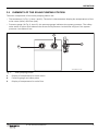
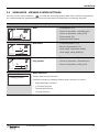
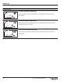
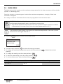
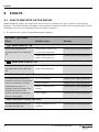
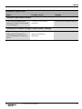
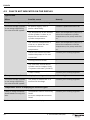
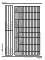
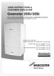
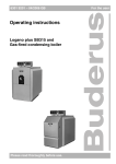
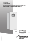
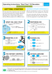
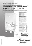
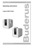
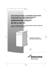
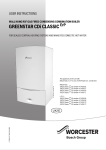
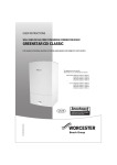
USER MANUAL
SOLAR THERMAL SYSTEM CONTROLLER
6720613720 00.1 SD
TDS 300
6 720 644 594 (2010/04)
UK/IE
CONTENTS
CONTENTS
1
1.1
1.2
Safety instructions and explanation of symbols
General safety instructions
Symbols
3
3
3
2
2.1
2.2
Details of the product
EU Declaration of Conformity
Product description
5
5
5
3
3.1
3.2
3.3
3.4
Operation
Elements of the solar pumping station
controller controls
View mode - viewing system settings
Main menu
8
9
10
11
13
4
4.1
4.2
Faults
Faults indicated on the display
Faults not indicated on the display
14
14
16
5
5.1
5.2
5.3
5.4
5.5
Notes for the user
Why is regular maintenance important?
Important notes on heat transfer fluids
Checking the solar thermal system
Checking operating pressure, with possible re-adjustment
Cleaning the collectors
18
18
18
18
19
19
6
User's log
20
2
6 720 644 594 (2010/04)
SAFETY INSTRUCTIONS AND EXPLANATION OF SYMBOLS
1
SAFETY INSTRUCTIONS AND EXPLANATION OF
SYMBOLS
1.1
GENERAL SAFETY INSTRUCTIONS
ABOUT THIS MANUAL
This manual contains important information about the safe and correct installation and operation of
the solar thermal system.
B Ask your heating engineer to provide you with all the technical documentation relating to the solar
thermal system.
B Read this manual carefully and keep it for future reference.
B Always observe the safety instructions to prevent injury and damage to property.
INTENDED USE
The solar controller (referred to from now on as the controller) may only be used for operating solar
thermal systems under the permissible ambient conditions (0 - 50 °C).
The programmer must not be used outdoors, in damp rooms or in rooms where easily combustible gas
mixtures could form.
B Only operate the solar thermal system as intended and when the system is in proper working order.
DOMESTIC HOT WATER TEMPERATURE
The recommended DHW storage temperature is 60 °C. Where storage temperatures in excess of 60 °C
may be achieved it is essential that the drawn hot water is controlled with a thermostatic blending
valve.
DISPOSAL
B Dispose of packaging in an environmentally responsible manner.
B When replacing components, dispose of the old parts in an environmentally responsible manner.
6 720 644 594 (2010/04)
3
SAFETY INSTRUCTIONS AND EXPLANATION OF SYMBOLS
1.2
SYMBOLS
Safety instructions in this document are identified by a warning-triangle symbol and are
printed on a grey background.
Signal words indicate the seriousness of the hazard in terms of the consequences of not following the
safety instructions.
•
Caution indicates that minor damage to property could result.
•
Warning indicates that minor personal injury or serious damage to property could result.
•
Danger indicates that serious personal injury could result. In particularly serious cases, lives could
be at risk.
Notes are identified by the symbol shown on the left. They are bordered by horizontal
lines above and below the text.
Notes contain important information in cases where there is no risk of personal injury or damage to
property.
4
6 720 644 594 (2010/04)
DETAILS OF THE PRODUCT
2
DETAILS OF THE PRODUCT
2.1
EU DECLARATION OF CONFORMITY
The design and operation of this product conform to the applicable European directives and
supplementary national requirements. Confirmity has been demonstrated.
2.2
PRODUCT DESCRIPTION
DIAGRAM OF SOLAR THERMAL SYSTEM
4
1
2
3
7747006071.01-1.SD
Fig. 1
1
2
3
4
System diagram
Collector array
Solar pumping station
Solar cylinder
Controller TDS 300
6 720 644 594 (2010/04)
5
DETAILS OF THE PRODUCT
Main components of the solar thermal system
Collector array
•
Consists of flat plate collectors or evacuated tube collectors
Solar pumping
station
•
Consists of the pump together with safety valves and shut-off valves for the
solar thermal circuit
Solar cylinder
•
Used for storing the collected solar energy
•
There are three different types:
– Domestic hot water cylinder (indirect)
– Thermal store (to back up a domestic heating system)
– Combination cylinder (for domestic heating back-up and for domestic
hot water)
Controller
TDS 300
•
Includes two temperature sensors
Tab. 1
OPERATING PRINCIPLE
When the set temperature difference between the collector array (Æ Fig. 1, Item 1) and the solar
storange cylinder (Æ Fig. 1, Item 3) is exceeded, the pump in the solar pumping station is switched on.
The pump transports the heat transfer fluid through the collector array to the solar cylinder. There is
a heat exchanger in the solar cylinder that transfers the free heat collected via the sun from the transfer
medium to the water intended for washing or heating.
6
6 720 644 594 (2010/04)
DETAILS OF THE PRODUCT
CONTROLLER
The controller is designed for use with a solar heating system. It can be mounted on a wall or is
integrated in a solar thermal centre.
In normal operating mode, the display screen (Æ Fig. 2) on the controller stays illuminated in green/
yellow for 5 minutes after the last button was pressed (activated by pressing the rotary selector ok
,
for example).
The display shows the following:
•
Pump and valve status (as simple schematic diagram not representative of actual system)
•
System values (e.g. temperatures)
•
Selected functions
•
Fault messages
1 5
Fig. 2
Possible display indications
6 720 644 594 (2010/04)
7
OPERATION
3
OPERATION
Your professional heating technician will set the solar thermal system when commissioning it, and it
will run automatically.
B Have your heating engineer explain to you how the solar thermal system works, and how to operate
it.
B Do not switch off the solar thermal system during long absences (e.g. when going on holiday).
When installed according to the manufacturer's specifications, the solar heating system is
intrinsically safe.
B After a power failure or a long absence, check the operating pressure on the pressure gauge of the
solar thermal system (Æ Section 5.4, page 19).
WARNING: Risk of damage to system if programmer settings are changed.
B Do not make any changes to any settings not described here.
8
6 720 644 594 (2010/04)
OPERATION
3.1
ELEMENTS OF THE SOLAR PUMPING STATION
The main components of the solar pumping station are:
•
Thermometers (Æ Fig. 3, Item 1 and 3): The built-in thermometers display the temperatures of the
solar return (blue) and flow (red).
•
Pressure gauge (Æ Fig. 3, Item 2): the pressure gauge indicates the system pressure. The safety
valve above it opens and releases the excess fluid pressure via the blow-off pipe if the system
pressure rises above 6 bar.
1
2
3
7747004985.09-1.SD
Fig. 3
1
2
3
Solar pumping station
Display of temperature for solar return
Pressure gauge and safety valve
Display of temperature for solar flow
6 720 644 594 (2010/04)
9
OPERATION
3.2
CONTROLLER CONTROLS
1
2
5
8
1
2
3
4
5
6
7
8
7
7747006072-23.1 SD
controller and display
Display
Rotary selector
Back button
Menu button
Symbol for temperature sensor
Displays of temperatures, hours of operation, etc.
Valve symbol (black = open outlet)
Active circulation diagram
Control
Rotary selector
(can be turned
and pressed)
Menu button
Symbol
+
ok
Functions
•
Selecting system settings
•
Opens the main menu
•
Returns display to collector temperature
-
menu
Back button
Tab. 2
SWITCHING OFF THE SYSTEM
B Disconnect the programmer from the mains power supply by means of the isolating device
(e.g. mains plug).
10
6
1 5
3
4
Fig. 4
1
6 720 644 594 (2010/04)
OPERATION
3.3
VIEW MODE - VIEWING SYSTEM SETTINGS
+
You can use the rotary selector
to view the following system data if the relevant components
are installed and the supplementary functions have been activated by your heating engineer.
Display
1 5
Supplementary function
System data
None
•
Temperature (°C)
•
Hours of operation, cumulative (h)
•
Hours of operation, today (h/d)
•
Pump speed (%)
•
Pump and valve status
•
Flow temperature (°C)
•
Return temperature (°C)
•
Heat usage, cumulative (kWh)
•
Heat usage, today (kWh/d)
•
Flow temperature (°C)
•
Hours of operation, cumulative (h)
•
Hours of operation, today (h/d)
Heat meter
5
7
8
Heat exchanger antiicing system
5
4
Other functions
Cooling function
Tab. 3
Other functions
Shows other active functions.
Possible indications (display flashes when function is active):
•
Evacuated tube collector
•
S. Europe function
•
Thermal disinfection
•
Cooling function
Overview of system data
6 720 644 594 (2010/04)
11
OPERATION
Status display
Cylinder maximum temperature
max.
min.
4
1 5
The cylinder maximum temperature is displayed if the set limit is
exceeded.
Collector minimum temperature
The collector minimum temperature is displayed if the temperature
drops below the set limit.
max.
1 5
Collector maximum temperature
The collector maximum temperature is displayed if the set limit is
exceeded.
Tab. 4
12
Status indications
6 720 644 594 (2010/04)
OPERATION
3.4
MAIN MENU
The Main menu can be used to set the maximum temperatures for the heat consumers (solar cylinder,
cylinder C, swimming pool).
Once the cylinder or swimming pool reaches the maximum temperature, charging of that heat
consumer is stopped.
If no entry is made for more than 60 seconds, the programmer exits the main menu.
WARNING: Risk of scalding if maximum cylinder temperature is set to more than 60 °C
and hot water thermostatic mixer is not fitted or set too high.
B Only set the maximum temperature of the solar cylinder to higher than 60 °C if a builtin thermostatic hot water mixer limits the outlet temperature to 60 °C.
If the domestic water supply is very hard, the maximum temperature of the solar cylinder
should not be set higher than 60 °C.
B Press the menu button to switch to the Main menu.
Main menu
Maximum solar
cylinder temp.
60°C
B Turn the rotary selector
+
-
to select the energy consumer
B To change the maximum temperature, press the rotary selector
flashing).
B To change the setting, turn the rotary selector
+
-
B To save the new setting, press the rotary selector
B To exit the Main menu, press the Back button
Setting range
Default setting
10 - 95 °C
60 °C
6 720 644 594 (2010/04)
ok
(temperature starts
.
.
ok
.
New setting
13
FAULTS
4
FAULTS
4.1
FAULTS INDICATED ON THE DISPLAY
When indicating a fault, the display is back-lit in red. In addition, the type of fault is indicated by
symbols. The individual fault messages can be retrieved using the rotary selector (by turning it). Fault
messages continue to be displayed until the fault is rectified.
B If a fault occurs, contact a qualified heating engineer.
Indication / Type of fault
Effect
Possible causes
Remedy
Temperature sensor not/
incorrectly connected.
Contact your heating engineer.
Temperature sensor or
sensor lead defective.
Contact your heating engineer.
Sensor failure S1 ...S8
Associated components
(pumps/valves) are switched
off.
Sensor short circuit S1 ...S8
Associated components
(pumps/valves) are switched
off.
Temperature sensor or
sensor lead defective.
Contact your heating engineer.
“No fluid flow in solar systems”/“secondary system”
The temperature difference
between collector temperature
sensor and bottom cylinder
temperature sensor or
between heat exchanger flow
temperature sensor and
bottom cylinder temperature
sensor is too great.
Air in the system.
Contact your heating engineer.
Pump is stalled.
Contact your heating engineer.
Valves or shut-offs are
closed.
Contact your heating engineer.
Pipe clogged.
Contact your heating engineer.
“Therm. disinfection running time error”
The thermal disinfection has
not been carried out.
Tab. 5
14
Target temperature not
reached.
Contact your heating engineer.
Possible faults indicated on the display
6 720 644 594 (2010/04)
FAULTS
Indication / Type of fault
Effect
Possible causes
Remedy
Collector connections
reversed.
Contact your heating engineer.
“Collector connections reversed”
The collector temperature
drops 15 K within 10 seconds
of switching on.
“Gravity fed circulation (at night) ”(Expert menu > Settings)
The cut-in temperature
differential for pump SP is
reached between 22:00 and
06:00.
Tab. 5
Gravity-feed restrictor
opened manually or
defective.
Contact your heating engineer.
Possible faults indicated on the display
6 720 644 594 (2010/04)
15
FAULTS
4.2
FAULTS NOT INDICATED ON THE DISPLAY
Type of fault
Effect
Possible causes
Remedy
Pump not running even though conditions for switching on are met.
The solar storage cylinder
is not being supplied by
the solar thermal system.
No power supply; fuse or
power cable faulty.
Contact a qualified electrician.
The temperature at the bottom
of the cylinder is close to, or
above the set maximum
cylinder temperature.
When the temperature drops 3 K
below the maximum cylinder
temperature, the pump switches
on.
The collector temperature is
close to, or above the set
maximum collector
temperature.
When the temperature drops 5 K
below the maximum collector
temperature, the pump switches
on.
There is no electrical power
lead to the pump or it is not
connected.
Contact your heating engineer.
Cooling function active.
–
The controller checks which
cylinder can be charged (only
in systems with two cylinders)
–
Pump is faulty.
Contact your heating engineer.
The system animation on the display is running and the pump is “humming”.
The solar storage cylinder
is not being supplied by
the solar thermal system.
The pump is stalled due to a
mechanical blockage.
Contact your heating engineer.
Temperature sensor is displaying an incorrect figure.
Pump is being activated/
deactivated too early/too
late.
Tab. 6
16
Temperature sensor incorrectly
fitted.
Incorrect temperature sensor
fitted.
Contact your heating engineer.
Possible faults not indicated on the display
6 720 644 594 (2010/04)
FAULTS
Type of fault
Effect
Possible causes
Remedy
Domestic hot water is too hot.
Risk of scalding
Cylinder temperature limit and
hot water mixing valve are set
too high.
Set the cylinder temperature limit
lower, inform engineer if
necessary.
Domestic hot water too cold (or domestic hot water flow volume too low).
Domestic hot water
temperature is set too low on
boiler control, on heating
programmer or on hot water
mixing valve.
Tab. 6
Contact your heating engineer.
Possible faults not indicated on the display
6 720 644 594 (2010/04)
17
NOTES FOR THE USER
5
NOTES FOR THE USER
5.1
WHY IS REGULAR MAINTENANCE IMPORTANT?
Your solar domestic hot water system or domestic hot water and space heating system is virtually
maintenance free.
However, we recommend that you have your system serviced at least every 2 years by your heating
engineer. In that way you can ensure smooth and efficient operation and early detection and
elimination of any possible damage.
5.2
IMPORTANT NOTES ON HEAT TRANSFER FLUIDS
WARNING: Risk of injury from contact with heat transfer fluid (water and propylene
glycol mixture).
B If heat transfer fluid comes into contact with eyes: hold eyelids wide open and
thoroughly rinse eyes with running water.
B Keep heat transfer fluid out of reach of children.
The heat transfer fluid is biodegradable.
Your engineer has been instructed to ensure, when commissioning the solar thermal system, that the
heat transfer fluid provides protection against freezing at temperatures down to at least – 30 °C.
5.3
CHECKING THE SOLAR THERMAL SYSTEM
You can contribute to the smooth functioning of your solar thermal system by doing the following:
•
Checking the temperature difference between flow and return and between the collector and
cylinder twice a year,
•
Checking the operating pressure for solar thermal stations
•
Checking the heat quantity (if a calorimeter has been installed) and/or the operating hours.
Enter the values in the log on page 20 (which may also be copied).
The completed log can help qualified technicians when checking your solar thermal
system and performing maintenance.
18
6 720 644 594 (2010/04)
NOTES FOR THE USER
5.4
CHECKING OPERATING PRESSURE, WITH POSSIBLE RE-ADJUSTMENT
Pressure fluctuations in the solar thermal circuit due to temperature changes are normal
and do not lead to faults in the solar thermal system.
B Check the system pressure on the pressure gauge (Æ Fig. 3) when the system is cold (about 20 °C).
IF PRESSURE DROPS
A pressure drop can be caused by the following:
•
There is a leak in the solar thermal circuit.
•
An automatic air vent has expelled air or vapour.
If the pressure of the solar thermal system has dropped:
B Check whether heat transfer fluid has collected in the storage vessel under the solar pumping
station.
B Call in a qualified heating engineer if the system pressure drops 0.5 bar below the level recorded in
the commissioning log (Æ Installation and servicing instructions for the solar station).
5.5
CLEANING THE COLLECTORS
DANGER: Risk of death by falling from roof
B Inspection, maintenance and cleaning work on the roof must only be carried out by
qualified technicians.
Due to the self-cleaning effect when rain falls, the collectors do not usually need cleaning.
6 720 644 594 (2010/04)
19
20
Tab. 8
Date
Log for solar thermal system values (can be copied)
Cylinder
System pressure
bottom (°C) in bar
Collector
(°C)
Solar flow (red) Solar return
in °C
(blue) in °C
Pressure gauge on
solar pumping
station
Solar pumping station:
Direction facing:
Temperatures displayed
on controller
Roof pitch:
Cylinder type:
Thermometers on solar pumping
station
Collector type:
Number of collectors:
Tab. 7
Date commissioned:
USER'S LOG
System operator:
6
Operating hours
in h and/or heat
quantity in kWh
Weather
conditions
1=clear sky
2=partly cloudy
3=very cloudy
4=overcast
USER'S LOG
6 720 644 594 (2010/04)
NOTES
6 720 644 594 (2010/04)
21
NOTES
22
6 720 644 594 (2010/04)
NOTES
6 720 644 594 (2010/04)
23
WORCESTER, BOSCH GROUP:
TECHNICAL SUPPORT: 0844 892 4010
APPOINTMENTS:
SPARES:
LITERATURE:
6 720 644 594
01905 752571
0844 892 9800
TRAINING:
01905 752526
SALES:
01905 752640
WEBSITE:
Worcester, Bosch Group
Cotswold Way, Warndon, Worcester WR4 9SW.
Tel. 0844 892 9900
Worcester, Bosch Group is a brand name of
Bosch Thermotechnology Ltd.
worcester-bosch.co.uk
0844 892 3000
worcester-bosch.co.uk