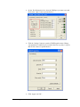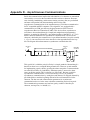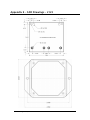
1
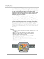
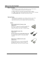
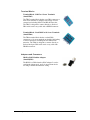
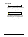
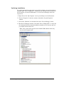
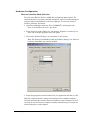
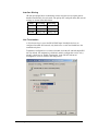
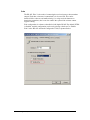
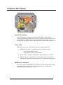
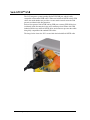
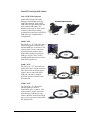
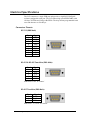
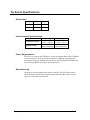
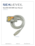
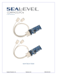
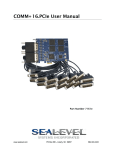
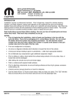
SeaLINK.SC User Manual Item Number 2123 www.sealevel.com PO Box 830 – Liberty, SC 29657 864.843.4343 Table of Contents INTRODUCTION......................................................................................................................... 1 BEFORE YOU GET STARTED................................................................................................. 2 WHAT’S INCLUDED ...................................................................................................................... 2 OPTIONAL ITEMS.......................................................................................................................... 2 INSTALLATION & CONFIGURATION.................................................................................. 4 SOFTWARE INSTALLATION ........................................................................................................... 4 HARDWARE INSTALLATION.......................................................................................................... 5 VERIFYING INSTALLATION ........................................................................................................... 6 HARDWARE CONFIGURATION ...................................................................................................... 7 HARDWARE DESCRIPTION.................................................................................................. 10 SEALATCH™ USB.................................................................................................................... 11 ELECTRICAL SPECIFICATIONS ......................................................................................... 13 CONNECTOR PINOUTS ................................................................................................................ 13 TECHNICAL SPECIFICATIONS ........................................................................................... 14 DIMENSIONS .............................................................................................................................. 14 ENVIRONMENTAL SPECIFICATIONS ............................................................................................ 14 POWER REQUIREMENTS ............................................................................................................. 14 MANUFACTURING ...................................................................................................................... 14 APPENDIX A - TROUBLESHOOTING ................................................................................. 15 APPENDIX B - HOW TO GET ASSISTANCE ...................................................................... 18 APPENDIX C – ELECTRICAL INTERFACES..................................................................... 19 APPENDIX D – ASYNCHRONOUS COMMUNICATIONS................................................ 20 APPENDIX E – CAD DRAWINGS – 2123 .............................................................................. 21 APPENDIX F - COMPLIANCE NOTICES ............................................................................ 22 FEDERAL COMMUNICATIONS COMMISSION STATEMENT ........................................................... 22 WARRANTY............................................................................................................................... 23 © Sealevel Systems, Inc. SL9200 Revision 8/2008 SeaLINK.SC User Manual Introduction Sealevel’s SeaLINK® 2123 USB to serial interface adapter offers an easy way to connect a DB9 serial device to a USB port. All configuration and electrical interface selections are handled through the driver, eliminating the need to open the enclosure to set jumpers or switches. The serial port is software configurable for RS-232, RS422, or RS-485 (full and half duplex) with the electrical interface settings maintained locally, allowing the host computer to be repaired or upgraded without reconfiguring the serial ports. Additionally, the 2123 can be configured at one computer and deployed to other computers. Sealevel SeaCOM USB software drivers and utilities make installation and operation easy for Windows 98SE, ME, 2000, XP, and Vista operating systems. Once the software is installed, plug the 2123 into an available USB port and the serial port is recognized as a standard COM port by the host system enabling compatibility with legacy software. Serial data rates to 921.6K bps are supported. To prevent accidental cable disconnection, the 2123 integrates a patent-pending SeaLATCH locking USB port, which is fully compatible with standard USB cables. When used with the included USB cable with a SeaLATCH USB type B connector, the metal thumbscrew provides a secure connection to the device. Standard operating temperature range is 0°C to 70°C and extended temperature range (-40°C to +85°C) is optional. Status LEDs display electrical interface selection and serial data activity. Features Serial port is software configurable for RS-232, RS-422, and two-wire or fourwire RS-485 Electrical interface settings maintained across multiple computers High speed UART with 128-byte Tx FIFO and 384-byte Rx FIFO Automatic hardware RS-485 enable/disable DB9M connector – serial port supports data rates to 921.6K bps Powered by USB host connection Full modem control signals implemented in RS-232 mode Status LEDs indicate power, electrical interface, and serial data activity Flexible mounting options DIN rail clips are available as an option © Sealevel Systems, Inc. -1- SeaLINK.SC User Manual Before You Get Started What’s Included The SeaLINK.SC is shipped with the following items. If any of these items is missing or damaged please contact Sealevel for replacement. 2123 – USB to RS-232/422/485 Two Port Serial Interface Adapter CA356 – USB Type A to SeaLATCH USB Type B Device Cable, 6’ in Length Sealevel Software CD – SeaCOM software and user manual Optional Items Depending upon your application, you are likely to find one or more of the following items useful. All items can be purchased from our website (http://www.sealevel.com) or by calling our sales team at 864-843-4343. Cables DB9F to DB25M (RS-232) Extension Cable (Item# CA177) The CA177 is a standard AT-style RS-232 modem cable with a DB9F connector on one end and a DB25M connector on the other. This cable is 72 inches in length. DB9F to DB9M Extension Cable (Item# CA127) The CA127 allows users to extend a DB9 cable up to six feet. The connectors are pinned one-to-one so the cable is compatible with any device or cable that has DB9 connectors. DB9F (RS-422) to DB25M (RS-530) Cable (Item# CA176) The CA176 allows users to convert any Sealevel RS422 DB9 Male asynchronous adapter to an RS-530 DB25 Male pinout. This cable is ten inches in length. © Sealevel Systems, Inc. -2- SeaLINK.SC User Manual Terminal Blocks Terminal Block – DB9F to 9 Screw Terminals (Item# TB05) The TB05 terminal block breaks out a DB9 connector to nine screw terminals to simplify field wiring of serial connections including RS-422 and RS-485 networks. The TB05 is designed to connect directly to Sealevel DB9 serial cards or any cable with a DB9M connector. Terminal Block – Dual DB9F to 18 Screw Terminals (Item# TB06) The TB06 terminal block breaks out dual DB9 connectors to 18 screw terminals to simplify field wiring of serial connections including RS-422 and RS-485 networks. The TB06 is designed to connect directly to Sealevel dual port DB9 serial cards or any cable with DB9M connectors. Adapters and Converters DB9F to RJ45 Modular Adapter (Item# RJ9S8) The RJ9S8 is a DB9 female to RJ45 adapter. It can be configured without tools, and it is an excellent choice for using available infrastructure wiring. © Sealevel Systems, Inc. -3- SeaLINK.SC User Manual Installation & Configuration Software Installation Windows 98/ME/ 2000/XP/Vista™ Operating Systems 1. Start Windows. 2. Insert the Sealevel Software CD in to your CD/DVD drive. 3. If ‘Auto-Start’ is enabled the installation window will automatically appear. Otherwise, navigate to the root directory of your CD drive and double-click the ‘autorun.exe’ application to launch the installation window. 4. Click the ‘Install’ button. 5. Type in your part number (2123) or select your adapter from the listing. 6. Click the ‘Install Drivers’ button. 7. The setup file will automatically detect the operating environment and install the proper components. To confirm that the SeaCOM driver has been successfully installed, click on the ‘Start’ button, and then select ‘All Programs’. You should see the ‘SeaCOM’ program folder listed. You are now ready to proceed with connecting the 2123 to your system. Refer to the Hardware Installation section for details. Windows NT is not USB aware and thus cannot support this device. © Sealevel Systems, Inc. -4- SeaLINK.SC User Manual Hardware Installation Do not connect the device to a USB port until the software has been successfully installed. To install the 2123, plug the device into an available USB port using the supplied USB cable. The following instructions were tested with Windows XP and may vary based on your version of Windows. Once the device has been connected, the Found New Hardware wizard will appear first for the root hub and then for each port that you are installing. Follow the instructions on the following page to finish installation. The installation will repeat twice for the COM port. This is a limitation in the way Windows installs external serial devices. 1. Click on ‘Install the software automatically’ followed by the ‘Next’ button. 2. Windows will show a warning message that the hardware has not passed Windows logo testing. Click on ‘Continue Anyway’. Note: all applications and drivers have been fully tested to maintain the integrity of your operating system. Clicking on ‘Continue anyway’ will not harm your system in any way. 3. Click on ‘Finish’. © Sealevel Systems, Inc. -5- SeaLINK.SC User Manual Verifying Installation To confirm that the drivers have been successfully installed, you can look in Device Manager under ‘Ports (COM &LPT)’ and the port you installed will be included on the list with the associated COM number. To access Device Manager, follow the steps below: 1. Right-click on the ‘My Computer’ icon on your desktop or in the Start menu. 2. Click on ‘Properties’ in the fly out menu to launch the ‘System Properties’ window. 3. Click on the ‘Hardware’ tab and then click on the ‘Device Manager’ button. 4. When Device Manager launches, look under ‘Ports (COM & LPT)’ to verify that the serial port has been correctly installed (screenshot of 2833 shown; only one port will be listed for the 2123). Note: Your system will assign the next available COM numbers which may vary for each computer used. © Sealevel Systems, Inc. -6- SeaLINK.SC User Manual Hardware Configuration Electrical Interface Mode Selection The 2123 offers RS-232, RS-422, and RS-485 (full and half duplex) modes. The electrical interface is a software selectable feature that can be accessed and changed using the Sealevel SeaCOM driver via Device Manager. To select the electrical interface, follow the steps below: 1. Open Device Manager and locate ‘Ports (COM&LPT)’ following the steps above. You should see the 2123’s port listed. 2. Select the port by right-clicking on it and selecting ‘Properties’ from the fly out menu. The serial port properties menu will appear 3. Click on the ‘Interface Settings’ tab (screenshot of 2833 shown) Note: The Sealevel SeaCOM driver adds the ‘Interface Settings’ tab. If this tab is missing, SeaCOM is not correctly installed. 4. Select the appropriate electrical interface for your application and click on ‘OK’. Note: The electrical interface settings are maintained across multiple computers. Once the SeaCOM software driver has been installed on target computers, the 2123 can easily be moved from one computer to another without having to configure the electrical interface at each computer. © Sealevel Systems, Inc. -7- SeaLINK.SC User Manual Interface Biasing 1K-ohm pull up/pull down combination resistors bias the receiver inputs and are handled automatically for each mode. The pull-up (PU) and pull-down (PD) resistor settings are shown in the table below. Mode PU Setting PD Setting RS-232 Always Off Always Off RS-422 Always Off Always Off RS-485 Always On Always On Line Termination A 120-ohm resistor is across the RS-422/485 input. If multiple devices are configured in an RS-485 network, only the devices on each end should have the termination in place. Termination configuration is software selectable for both full- and half-duplex RS485. By default, line termination is disabled, and this configuration can be set by placing a check next to ‘Enable Termination’ in the ‘RS-485 Advanced Configuration’ field, as shown in the image below. © Sealevel Systems, Inc. -8- SeaLINK.SC User Manual Echo The RS-485 ‘Echo’ is the result of connecting the receiver inputs to the transmitter outputs. Each time a character is transmitted; it is also received. This can be beneficial if the software can handle echoing (i.e. using received characters to throttle the transmitter), but it can also confuse the system if the software cannot support echoing. Echo configuration is software selectable for half-duplex RS-485. By default, ECHO is disabled, and this configuration can be set by placing a check next to ‘Enable Echo’ in the ‘RS-485 Advanced Configuration’ field, as pictured below. © Sealevel Systems, Inc. -9- SeaLINK.SC User Manual Hardware Description SeaLATCH™ USB Port The 2123 integrates a patent-pending SeaLATCH USB port, which is fully compatible with standard USB cables. When used with the included USB cable with a SeaLATCH type B USB connector, the metal thumbscrew provides a secure metal-to-metal connection to the device and prevents accidental cable disconnection. Status LEDs Status LEDs on the front of the 2123 indicate the following information: MODE (Red or Green) – Indicates the electrical interface selected o Green indicates RS-232 mode o Red indicates RS-422 or RS-485 mode DATA (Green) – Blinks to indicate data is being transmitted or received EN[able] (Green) – Lights when the hub is properly powered through the USB port and communication between the device and host has been enabled DB9M Serial Connectors The 2123 includes a single DB9M serial connector with full modem control signals implemented in RS-232 mode. Pin outs for the connector are included in the following Electrical Specifications section. © Sealevel Systems, Inc. - 10 - SeaLINK.SC User Manual SeaLATCH™ USB The 2123 integrates a patent-pending SeaLATCH USB port, which is fully compatible with standard USB cables. When used with SeaLATCH locking USB cables, the metal thumbscrew provides a secure metal-to-metal connection and prevents accidental cable disconnection. Sealevel incorporates SeaLATCH locking USB ports on many USB I/O devices. Accidental cable disconnection is the most common point of failure with USB industrial I/O devices and SeaLATCH cables and connectors prevents that while being fully compatible with standard USB cables. The image below shows the 2123 secured with the included SeaLATCH cable. © Sealevel Systems, Inc. - 11 - SeaLINK.SC User Manual SeaLATCH Locking USB Cables SeaLATCH USB Connectors SeaLATCH locking USB cables integrate a small thumbscrew into each USB connector. SeaLATCH USB cables are fully interchangeable with standard USB cables. The thumbscrew provides a secure metalto-metal connection preventing accidental disconnection. SeaLATCH USB cables are available in three configurations. Item# CA356 The CA356 is a 72” USB cable with a SeaLATCH type B connector and a standard USB type A connector. This cable provides a secure connection between Sealevel products with a SeaLATCH type B port and legacy USB type A ports. The CA356 is included with Sealevel devices with a SeaLATCH type B port. Item# CA332 The CA332 is a 72” cable with both SeaLATCH type A and B connectors. This cable secures both ends of the cable to devices with SeaLATCH USB ports and offers complete protection against accidental cable disconnection. Item# CA355 The CA355 is a 72” cable with a standard USB type B and a SeaLATCH type A connector. This cable provides a secure connection between legacy USB devices and Sealevel products with a SeaLATCH type A port, such as the isolated USB hub (Item# 270U). © Sealevel Systems, Inc. - 12 - SeaLINK.SC User Manual Electrical Specifications The 2123 connects to a single USB port and provides a single RS-232/422/485 software configurable serial port. The 2123 utilizes high speed USB/UARTs with 128-byte Tx FIFOs and 384-byte Rx FIFOs. The chips feature programmable baud rates and data rates to 921.6K bps. Connector Pinouts RS-232 (DB9 Male) Pin # 1 2 3 4 5 6 7 8 9 Signal DCD RX TX DTR GND DSR RTS CTS RI RS-422 & RS-485 Four-Wire (DB9 Male) Pin # 1 2 3 4 5 Signal RX+ RXTXTX+ GND Note: Pins 6-9 are ‘no connect’ RS-485 Two-Wire (DB9 Male) Pin # 3 4 5 Signal DATADATA+ GND Note: Pins 1, 2, 6-9 are ‘no connect’ © Sealevel Systems, Inc. - 13 - SeaLINK.SC User Manual Technical Specifications Dimensions Length Width Height 4.3” 3.4” 1.3” 10.9cm 8.6cm 3.3cm Environmental Specifications Specification Temperature Range Humidity Range Operating 0°C – 70°C (32°F – 158°F) 10 to 90% R.H. Non-Condensing Storage -50°C – 105°C (-58°F – 221°F) 10 to 90% R.H. Non-Condensing Power Requirements This device is a high power USB device. It must be plugged directly into a USB port on your computer or a self-powered hub capable of supplying 200 mA per port. Some laptop computers running on battery power and non-powered USB hubs may not provide the 200mA necessary to power this device. Manufacturing All Sealevel Systems printed circuit boards are built to UL 94V0 rating and are 100% electrically tested. These printed circuit boards are solder mask over bare copper or solder mask over tin nickel. © Sealevel Systems, Inc. - 14 - SeaLINK.SC User Manual Appendix A - Troubleshooting The adapter should provide years of trouble-free service. However, in the event that it appears to be functioning incorrectly, the following tips can eliminate most common problems without the need to call Technical Support. 1. Ensure that the Sealevel Systems SeaCOM software has been installed on the machine so that the necessary files are in place to complete the installation. To confirm installation, click on the Windows ‘Start’ button and then select ‘All Programs’. You should see the ‘SeaCOM’ program folder listed. Note: The SeaCOM driver must be installed before the adapter is connected to your computer. 2. Check to make sure that USB support is enabled and functioning properly in the operating system. The presence of the ‘Universal Serial Bus controllers’ listing in Device Manager will confirm that USB support is enabled in Windows 98SE, ME, 2000, XP, or Vista operating systems. 3. While Device Manager is open, locate the COM ports (described under “Verifying Installation” in the Installation and Configuration section of this manual). 4. Once you have confirmed that the COM ports are listed in Device Manager, you can use the Sealevel WinSSD utility and a loopback plug to test communications. Detailed help is included in the WinSSD utility. If you have a loopback plug, put it on the DB9 connector that you want to test. If you don’t have a loopback plug, contact Technical Support for assistance. If you’re testing RS-485 mode, you’ll need to have ECHO enabled otherwise the following test will fail. Refer to the Hardware Configuration section for instructions on enabling ECHO. To test communications, launch the WinSSD utility in the SeaCOM folder under the ‘Start’ menu. © Sealevel Systems, Inc. - 15 - SeaLINK.SC User Manual On the ‘Port Information’ tab, select the COM port you want to test and click on the ‘Open’ button. (pictured below) Click the ‘Settings’ button to open the COM Properties menu. Change your parameters to 9600 bits per second, 8 data bits, no parity, 1 stop bit, and no flow control, as pictured below. Click ‘Apply’ and ‘Ok’. © Sealevel Systems, Inc. - 16 - SeaLINK.SC User Manual Select the ‘BERT’ tab and with the loopback connected to the port you wish to test, click on the ‘Start’ button. If testing RS-485, be sure that ECHO is enabled. (Pictured below) If the COM port is working properly, the green light will glow and the Transmit Frames and Receive Frames will increase. The Tx and Rx Data Rates will show the calculated data rate. (Pictured below) You can continue testing this port with different configurations or proceed with testing other ports, if necessary. If these steps do not solve your problem, please call Sealevel Systems’ Technical Support, (864) 843-4343. Our technical support is free and available from 8:00 AM to 5:00 PM Eastern Time Monday through Friday. For email support, contact [email protected]. © Sealevel Systems, Inc. - 17 - SeaLINK.SC User Manual Appendix B - How To Get Assistance Begin by reading the Troubleshooting Guide in Appendix A. This will help solve most common problems. When calling for technical assistance, please have the device installed and ready to run diagnostics. If possible, have your user manual and current adapter settings ready. The Sealevel website is an excellent resource. Our homepage is located online at http://www.sealevel.com. The most current software updates and user manuals are available via our homepage by clicking on the 'Drivers' or 'Manuals' links located under ‘Technical Support.’ Manuals and software can also be downloaded from the product page for your device. The FAQ section of our website answers many common questions. Refer to this helpful resource by visiting http://www.sealevel.com/faq.asp. Technical support is available Monday through Friday from 8:00am to 5:00pm EST and can be reached by phone at +1 (864) 843-4343 or via email at [email protected]. RETURN AUTHORIZATION MUST BE OBTAINED FROM SEALEVEL SYSTEMS BEFORE RETURNED MERCHANDISE WILL BE ACCEPTED. AUTHORIZATION CAN BE OBTAINED BY CALLING SEALEVEL SYSTEMS AND REQUESTING A RETURN MERCHANDISE AUTHORIZATION (RMA) NUMBER. © Sealevel Systems, Inc. - 18 - SeaLINK.SC User Manual Appendix C – Electrical Interfaces RS-232 Quite possibly the most widely used communication standard is RS-232. This implementation has been defined and revised several times and is often referred to as RS232 or EIA/TIA-232. The IBM PC computer defined the RS-232 port on a 9 pin D sub connector and subsequently the EIA/TIA approved this implementation as the EIA/TIA574 standard. This standard is defined as the 9-Position Non-Synchronous Interface between Data Terminal Equipment and Data Circuit-Terminating Equipment Employing Serial Binary Data Interchange. Both implementations are in wide spread use and will be referred to as RS-232 in this document. RS-232 is capable of operating at data rates up to 20 Kbps at distances less than 50 ft. The absolute maximum data rate may vary due to line conditions and cable lengths. RS-232 is a single ended or unbalanced interface, meaning that a single electrical signal is compared to a common signal (ground) to determine binary logic states. The RS-232 and the EIA/TIA-574 specification define two types of interface circuits, Data Terminal Equipment (DTE) and Data Circuit-Terminating Equipment (DCE). RS-422 The RS-422 specification defines the electrical characteristics of balanced voltage digital interface circuits. RS-422 is a differential interface that defines voltage levels and driver/receiver electrical specifications. On a differential interface, logic levels are defined by the difference in voltage between a pair of outputs or inputs. In contrast, a single ended interface, for example RS-232, defines the logic levels as the difference in voltage between a single signal and a common ground connection. Differential interfaces are typically more immune to noise or voltage spikes that may occur on the communication lines. Differential interfaces also have greater drive capabilities that allow for longer cable lengths. RS-422 is rated up to 10 Megabits per second and can have cabling 4000 feet long. RS-422 also defines driver and receiver electrical characteristics that will allow one driver and up to 32 receivers on the line at once. RS-422 signal levels range from 0 to +5 volts. RS-422 does not define a physical connector. RS-485 RS-485 is backwardly compatible with RS-422; however, it is optimized for party line or multi-drop applications. The output of the RS-422/485 driver is capable of being Active (enabled) or Tri-State (disabled). This capability allows multiple ports to be connected in a multi-drop bus and selectively polled. RS-485 allows cable lengths up to 4000 feet and data rates up to 10 Megabits per second. The signal levels for RS-485 are the same as those defined by RS-422. RS-485 has electrical characteristics that allow for 32 drivers and 32 receivers to be connected to one line. This interface is ideal for multi-drop or network environments. RS-485 tri-state driver (not dual-state) will allow the electrical presence of the driver to be removed from the line. Only one driver may be active at a time and the other driver(s) must be tri-stated. RS-485 can be cabled in two ways, two-wire and fourwire mode. Two-wire mode does not allow for full duplex communication, and requires that data be transferred in only one direction at a time. For half-duplex operation, the two transmit pins should be connected to the two receive pins (Tx+ to Rx+ and Tx- to Rx-). Four-wire mode allows full duplex data transfers. RS-485 does not define a connector pinout or a set of modem control signals. RS-485 does not define a physical connector. © Sealevel Systems, Inc. - 19 - SeaLINK.SC User Manual Appendix D – Asynchronous Communications Serial data communications implies that individual bits of a character are transmitted consecutively to a receiver that assembles the bits back into a character. Data rate, error checking, handshaking, and character framing (start/stop bits) are pre-defined and must correspond at both the transmitting and receiving ends. Asynchronous communications is the standard means of serial data communication for PC compatible and PS/2 computers. The original PC was equipped with a communication or COM: port that was designed around an 8250 Universal Asynchronous Receiver Transmitter (UART). This device allows asynchronous serial data to be transferred through a simple and straightforward programming interface. A starting bit followed by a pre-defined number of data bits (5, 6, 7, or 8) defines character boundaries for asynchronous communications. The end of the character is defined by the transmission of a pre-defined number of stop bits (usually 1, 1.5 or 2). An extra bit used for error detection is often appended before the stop bits. The diagram below demonstrates asynchronous communication bits. Idle state of line 5 to 8 Data Bits Odd, Even or Unused Remain Idle or next start bit 1 P BIT STOP 0 1 1.5 2 This special bit is called the parity bit. Parity is a simple method of determining if a data bit has been lost or corrupted during transmission. There are several methods for implementing a parity check to guard against data corruption. Common methods are called (E)ven Parity or (O)dd Parity. Sometimes parity is not used to detect errors on the data stream. This is refereed to as (N)o parity. Because each bit in asynchronous communications is sent consecutively, it is easy to generalize asynchronous communications by stating that each character is wrapped (framed) by pre-defined bits to mark the beginning and end of the serial transmission of the character. The data rate and communication parameters for asynchronous communications have to be the same at both the transmitting and receiving ends. The communication parameters are baud rate, parity, number of data bits per character, and stop bits (i.e. 9600,N,8,1). © Sealevel Systems, Inc. - 20 - SeaLINK.SC User Manual Appendix E – CAD Drawings – 2123 © Sealevel Systems, Inc. - 21 - SeaLINK.SC User Manual Appendix F - Compliance Notices Federal Communications Commission Statement FCC - This equipment has been tested and found to comply with the limits for Class A digital device, pursuant to Part 15 of the FCC Rules. These limits are designed to provide reasonable protection against harmful interference when the equipment is operated in a commercial environment. This equipment generates, uses, and can radiate radio frequency energy and, if not installed and used in accordance with the instruction manual, may cause harmful interference to radio communications. Operation of this equipment in a residential area is likely to cause harmful interference in such case the user will be required to correct the interference at the users expense. EMC Directive Statement Products bearing the CE Label fulfill the requirements of the EMC directive (89/336/EEC) and of the low-voltage directive (73/23/EEC) issued by the European Commission. To obey these directives, the following European standards must be met: EN55022 Class A - “Limits and methods of measurement of radio interference characteristics of information technology equipment” EN55024 – “Information technology equipment Immunity characteristics Limits and methods of measurement”. EN60950 (IEC950) - “Safety of information technology equipment, including electrical business equipment” Warning This is a Class A Product. In a domestic environment, this product may cause radio interference in which case the user may be required to take adequate measures to prevent or correct the interference. Always use cabling provided with this product if possible. If no cable is provided or if an alternate cable is required, use high quality shielded cabling to maintain compliance with FCC/EMC directives. © Sealevel Systems, Inc. - 22 - SeaLINK.SC User Manual Warranty Sealevel's commitment to providing the best I/O solutions is reflected in the Lifetime Warranty that is standard on all Sealevel manufactured products. We are able to offer this warranty due to our control of manufacturing quality and the historically high reliability of our products in the field. Sealevel products are designed and manufactured at its Liberty, South Carolina facility, allowing direct control over product development, production, burn-in and testing. Sealevel Systems, Inc. (hereafter "Sealevel") warrants that the Product shall conform to and perform in accordance with published technical specifications and shall be free of defects in materials and workmanship for life. In the event of failure, Sealevel will repair or replace the product at Sealevel's sole discretion. Failures resulting from misapplication or misuse of the Product, failure to adhere to any specifications or instructions, or failure resulting from neglect or abuse are not covered under this warranty. Warranty service is obtained by delivering the Product to Sealevel and providing proof of purchase. Return authorization must be obtained from Sealevel Systems before returned merchandise will be accepted. Authorization is obtained by calling Sealevel Systems and requesting a Return Merchandise Authorization (RMA) number. The Customer agrees to insure the Product or assume the risk of loss or damage in transit, to prepay shipping charges to Sealevel, and to use the original shipping container or equivalent. Warranty is valid only for original purchaser and is not transferable. Sealevel Systems assumes no liability for any damages, lost profits, lost savings or any other incidental or consequential damage resulting from the use, misuse of, or inability to use this product. Sealevel Systems will not be liable for any claim made by any other related party. This warranty applies to Sealevel manufactured Product. Product purchased through Sealevel but manufactured by a third party will retain the original manufacturer's warranty. Sealevel Systems, Incorporated 2779 Greenville Highway P.O. Box 830 Liberty, SC 29657 USA (864) 843-4343 FAX: (864) 843-3067 www.sealevel.com email: [email protected] Technical Support is available Monday - Friday from 8 a.m. to 5 p.m. Eastern time Trademarks Sealevel Systems, Incorporated acknowledges that all trademarks referenced in this manual are the service mark, trademark, or registered trademark of the respective company. © Sealevel Systems, Inc. - 23 - SeaLINK.SC User Manual