1
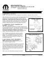
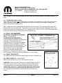
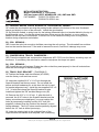
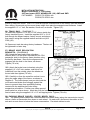
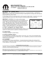
INSTALLATION INSTRUCTIONS Mopar Performance 2” Lift System 2007 and newer JEEP WRANGLER (JK) 4WD and 2WD PART NUMBER P5155207, P5155789 4-door P5155208, P5155790 2-door INTRODUCTION Installation requires a professional mechanic. Prior to beginning, inspect the vehicles steering, driveline, and brake systems, paying close attention to the suspension link arms and bushings, stabilizer bars and bushings, tie rod ends, pitman arm, ball joints and wheel bearings. Also check the steering sector-to-frame and all suspension-to-frame attaching points for stress cracks. The overall vehicle must be in excellent working condition; repair or replace all worn parts. Read instructions several times before starting. Be sure you have all needed parts and know where they install. Read each step completely as you go. NOTES: • Prior to beginning the installation, check all parts and hardware in the box with the parts list below. If you find a packaging error, contact Mopar directly. Do not contact the dealer where the system was originally purchased. You will need the control number from each box when calling; this number is located at the bottom of the part number label and to the right of the bar code. • Front end realignment is necessary. • An arrow on diagrams indicates which direction is toward the front of the vehicle. • A foot-pound torque reading is given in parenthesis ( ) after each appropriate fastener. • Do not fabricate any components to gain additional suspension height. • Prior to drilling or cutting, check behind the surface being worked on for any wires, lines, or hoses that could be damaged. • After drilling, file smooth any burrs and sharp edges. • Paint or undercoat all exposed metal surfaces. • Prior to attaching components, be sure all mating surfaces are free of grit, grease, excessive undercoating, etc. • A factory service manual should be on hand for reference. • Use the check-off box “” found at each step to help you keep your place. Two “” denotes that one check-off box is for the driver side and one is for the passenger side. K6857183 06/15/10 ©2008, Chrysler, LLC. Mopar is a registered trademark of Chrysler, LLC. All rights reserved. Page 1 of 17 INSTALLATION INSTRUCTIONS Mopar Performance 2” Lift System 2007 and newer JEEP WRANGLER (JK) 4WD and 2WD PART NUMBER P5155207, P5155789 4-door P5155208, P5155790 2-door Wheel and Tire Recommendations NOTE: The use of 35” diameter tires may require modification to Mopar rock rails, and certain model Mopar bumpers, for adequate clearance. Tire Diameter: 33” to 35” Tire Width: No greater than 12.5” NOTE: Tires wider than 10.5” may require wheels with dimensions as follows: Wheel Diameter: No less than 17” Wheel Width: 8”- 9” Wheel Back Spacing: 3.25” to 4.75”. As backspacing dimension decreases, track width and stability increases. NOTE: Vehicle RPM and speedometer readings are based on the stock vehicle’s tire and wheel combinations. Installing larger wheels and tires with your Mopar Performance lift kit could result in incorrect RPM, speedometer and odometer readings. PARTS LIST … The part number is stamped into each part or printed on an adhesive label. Identify each part and place the appropriate mounting hardware with it. PART NO. DESCRIPTION NEW ATTACHING HARDWARE (Qty.) (Qty.- if more than one) BAG # 780178………………….(2) Coil spring, front 2” 780180 ......................... (2) Coil spring, rear, 2” four-door model only OR 780171 ........................ (2) Coil spring, rear, 2” two-door model only 07-5702 ....................... (2) compression travel dampener, rear 716236 ........................ track bar, front ............................. (2) 9/16” x 3” bolt……………...716247 (4) 9/16” SAE washer (2) 9/16” Stover nut (1) 1” OD x 1-9/16” sleeve (2) bushing half (1) 1/4” grease fitting (1) Heim joint end (2) Heim spacer (1) 3/4” jam nut K6857183 06/15/10 ©2008, Chrysler, LLC. Mopar is a registered trademark of Chrysler, LLC. All rights reserved. Page 2 of 17 INSTALLATION INSTRUCTIONS Mopar Performance 2” Lift System 2007 and newer JEEP WRANGLER (JK) 4WD and 2WD PART NUMBER P5155207, P5155789 4-door P5155208, P5155790 2-door 55-33-5704 ................. front brake hose relocation .......... (1) 1/4” x 3/4” bolt……………. 716238 bracket, driver side (1) 1/4” SAE washer (1) 1/4” Nyloc nut 55-34-5704 ................. front brake hose relocation .......... (1) 1/4” x 3/4” bolt……………..716238 bracket, passenger side (1) 1/4” SAE washer (1) 1/4” Nyloc nut 55-21-5704 ................. bracket, brake hose ..................... (1) 1/4” x 3/4” bolt……………..716238 relocation, driver side / rear (1) 1/4” SAE washer (1) 1/4” Nyloc nut (1) 1/4" x 1/2" self-tapping bolt (1) Adel line clamp 55-22-5704 ................. bracket, brake hose……………….(1) 1/4” x 3/4” bolt……………..716238 relocation, pass. side / rear (1) 1/4” SAE washer (1) 1/4” Nyloc nut (1) 1/4" x 1/2" self-tapping bolt (1) Adel line clamp 716242 ......................... bracket, track bar, rear ................ (1) 9/16” x 3-1/4” bolt………… 716237 (1) 9/16” SAE washer (1) 12-5700 tab nut (1) 1/2” x 1” bolt (1) 1/2” Stover nut (1) 1/2” SAE washer (1) 1-1/4” OD x 1-5/8” sleeve (2) 3/8” x 3” x 3-1/4” U-bolt (4) 3/8” serrated flange nut 26-5704 ........................ (2) alignment cam bolt assembly………………………………………716245 716244 ......................... (2) stabilizer bar link, rear………...(2) 1/2" Nyloc nut, fine thread.….716239 (2) 1/2" jam nut (4) 1/2" SAE washer (2) hourglass bushing (2) 3/4” OD x 1-7/16” sleeve (2) link upper end, 90 degree front stabilizer bar link………….....(2) washer, front stabilizer bar.…716245 hardware .5” ID x 1.6” OD x .1875” thick 716243….. ……….…. . (2) compression dampener...……(2) 5/16” x 1-3/4”…….……………716245 K6857183 06/15/10 ©2008, Chrysler, LLC. Mopar is a registered trademark of Chrysler, LLC. All rights reserved. Page 3 of 17 INSTALLATION INSTRUCTIONS Mopar Performance 2” Lift System 2007 and newer JEEP WRANGLER (JK) 4WD and 2WD PART NUMBER P5155207, P5155789 4-door P5155208, P5155790 2-door pad spacer, front self-tapping bolt parking brake cable relocation ..... (2) 1/4” x 1/2” …………….………716238 hardware self-tapping bolt Part numbers depend on type ordered…………………….. (4) shock absorbers w/ boot (2) hardware pack, cable tie 55-03-92075 ................ bracket, steering stabilizer-to- ..... (1) 1/2” x 2-1/2” bolt…………...…716248 tie rod (1) 1/2" Stover nut (1) 7/16” USS washer (2) 3/8” x 2-1/2” U-bolt (4) 3/8” flange nut (1) 1/2” ID x 1-3/8” sleeve 55-02-92075 ................ bracket, steering stabilizer-to- ..... (1) 1/2” x 1” bolt…………………..716248 axle (1) 1/2” Stover nut (1) 1/2” SAE washer (1) 1/2” mounting stud *(1) 1/2” nut *(1) 1/2” lockwasher *(1) 7/16” nut *(1) 7/16” lockwasher *(1) 7/16” USS washer * Denotes that this hardware is bagged with 1/2” mounting stud. 01-81195 ..................... steering stabilizer cylinder 716249…......................Mopar decal sheet………………….……...in Installation Instructions packet 118X238AP……………alcohol cleaning pad……………………..…in Installation Instructions packet K6857183 06/15/10 ©2008, Chrysler, LLC. Mopar is a registered trademark of Chrysler, LLC. All rights reserved. Page 4 of 17 INSTALLATION INSTRUCTIONS Mopar Performance 2” Lift System 2007 and newer JEEP WRANGLER (JK) 4WD and 2WD PART NUMBER P5155207, P5155789 4-door P5155208, P5155790 2-door FRONT DISASSEMBLY NOTE: Save all factory components and hardware for reuse, unless noted. 1) PREPARE VEHICLE… Place vehicle in neutral. Raise front of vehicle with a jack and secure a jack stand beneath each frame rail, behind the front / lower link arms. Ease the frame down onto the stands, place transmission in low gear or “park”, and chock rear tires. Remove front tires. Position a jack so that it supports, but does not raise, the front axle. 2) TRACK BAR… Remove the bolts securing the front track bar-to-axle and frame. The bar and hardware will not be re-used. 3) STABILIZER BAR LINKS, SHOCK ABSORBERS… Remove and discard the front stabilizer bar links. Remove and discard the shock absorbers. 4) BRAKE HOSES, WIRING, AXLE VENT HOSE… Detach the factory brake hose bracket (one per side) at the frame. This bracket holds the connection between the rubber brake hose and the metal brake line. The following steps provide adequate wiring / vent hose length to accommodate additional suspension extension travel: On each side, a clip attaches the ABS wire loom to the top / inboard side of the shock tower. Remove and discard the clip. The upper end of the axle vent hose is clamped to the driver side frame rail. Leave the hose attached to frame; simply pull down approximately 3” of hose. On Rubicon models, the wiring loom for the locking differential is attached to the axle-to-frame upper link. Remove and discard the clip. 5) DRIVESHAFT… Unbolt the front driveshaft at the front axle then tie it up and out of the way. Do not let the shaft “hang”; this risks pinching / damaging the grease boot at the transfer case end. 6) AXLE LINK ARMS, COIL SPRINGS… Loosen, but do not remove, the upper and lower link arm bolts at the axle and frame. Lower the axle enough to facilitate removing the front coil springs. Remove the coil springs. K6857183 06/15/10 ©2008, Chrysler, LLC. Mopar is a registered trademark of Chrysler, LLC. All rights reserved. Page 5 of 17 INSTALLATION INSTRUCTIONS Mopar Performance 2” Lift System 2007 and newer JEEP WRANGLER (JK) 4WD and 2WD PART NUMBER P5155207, P5155789 4-door P5155208, P5155790 2-door FRONT ASSEMBLY 7) CAM BOLTS… [DIAGRAM 1] NOTE: If the vehicle has ever been realigned, it may already be equipped with cam bolts. One side at a time, remove the bolt securing the lower link arm-to-axle then remove the rear knock-outs that change the opening from a square hole to a slotted hole. A special tool is available for this, or use a die grinder with a small cutting wheel. Install the cam bolts from the outside. Rotate the cams so that the front axle is shifted as far forward as possible (the bolt head will be in its most rearward position). Snug-up the bolts; do not fully tighten at this time. 8) COMPRESSION TRAVEL DAMPENER PAD SPACERS… [DIAGRAM 2] The compression pad spacer (#716243) installs on top of the coil spring’s lower seat. The otherwise round seat has a flat edge that faces outboard. Locate center for the hole to be drilled by using the dimensions in Diagram 2; note that the compression pad spacer is installed slightly outboard of seat center. Drill at the marked location using a 17/64” bit. Thread the just-drilled hole using the supplied 5/16” x 1-3/4” self-tapping bolt then remove the bolt. NOTE: The compression pad spacer must first be inserted into the coil spring before it is bolted to the coil seat; see next step. 9) COIL SPRINGS, SHOCK ABSORBERS… NOTE: Perform step 9 one side at a time. Be sure the factory rubber isolators are still in place inside the upper coil tower. Insert the compression pad spacer into the bottom of the coil spring and hold it in place. Insert the coil spring into the upper tower first, followed by the lower seat. Be sure that the coils are indexed so they seat properly then raise the axle enough to hold the coil springs in place. Position the compression pad spacer onto the K6857183 06/15/10 ©2008, Chrysler, LLC. Mopar is a registered trademark of Chrysler, LLC. All rights reserved. Page 6 of 17 INSTALLATION INSTRUCTIONS Mopar Performance 2” Lift System 2007 and newer JEEP WRANGLER (JK) 4WD and 2WD PART NUMBER P5155207, P5155789 4-door P5155208, P5155790 2-door lower spring seat then secure it using the supplied 5/16” x 1-3/4” selftapping bolt and tighten (200 in-lb). Install shock absorber. Tighten the upper hardware until bushings swell slightly. Install the lower shock bolts, but do not tighten at this time. Apply Mopar decals. After the shock absorber installation is complete, the jack can be lowered and relocated to allow installation on the opposite side. 10) TRACK BAR… Thoroughly coat the supplied Urethane bushing halves and the 1” OD x 1-9/16” sleeve with a light, Silicone or Lithium based grease. Insert bushings / sleeve into the track bar eye. Install the supplied grease fitting. Apply anti-seize to the Mopar Heim joint. Thread the supplied jam nut onto the Mopar Heim joint then loosely thread the Heim into the bar. Set the overall length of the bar to 32-5/8" measured between eye centers. This will serve as a baseline prior to final adjustment. Do not tighten the jam nut at this time. Place one supplied Heim spacer on each side of the Heim end then position the assembly in the track bar mount on the axle. Insert the supplied 9/16” x 3” bolt to temporarily hold the track bar in place. This end of the track bar must be detached from the axle again in a later step so do not install its nut and washers at this time. Connect upper end of bar-to-frame using the supplied 9/16” x 3” bolt, SAE washers, and Stover nut; place a washer on both the bolt head and nut side. Do not tighten at this time. NOTE: Final track bar adjustment and tightening are performed in later steps. NOTE: The track bar must be greased during each oil change / service. 11) BRAKE HOSES… [DIAGRAM 3] Attach the appropriate brake hose relocation bracket (#5533-5704 driver side; #55-34-5704 passenger side) to the factory brake hose. Use the supplied 1/4” x 3/4” bolt, facing outward. The washer is used on the bolt head side. Install the supplied Nyloc nut and tighten (76 in-lb). K6857183 06/15/10 ©2008, Chrysler, LLC. Mopar is a registered trademark of Chrysler, LLC. All rights reserved. Page 7 of 17 INSTALLATION INSTRUCTIONS Mopar Performance 2” Lift System 2007 and newer JEEP WRANGLER (JK) 4WD and 2WD PART NUMBER P5155207, P5155789 4-door P5155208, P5155790 2-door Carefully re-form the metal brake line then attach the Mopar bracket to the factory location. (76 in-lb). 12) STABILIZER BAR LINKS… Remove the factory rear stabilizer bar-to-axle links, and install them on the front of the vehicle. Attach the swivel (upper) end of the stabilizer bar link-to-bar body (the stud faces inboard) then secure using factory hardware (66). Attach the lower (eye ring) end of stabilizer bar link-to-axle. The eye ring seats against the inboard side of the mounting tab. The factory mounting bolt installs from the outboard side through the mounting tab then through the eye ring. Position one .5” ID x 1.6” OD x .1875” thick washer onto the factory mounting bolt, install factory nut then tighten (75). 13) FRONT CROSSMEMBER, AUTOMATIC TRANSMISSION MODEL ONLY… [DIAGRAM 4] Most models with automatic transmissions are equipped with a transmission pan skid plate / crossmember assembly. The forward lip of the crossmember must be trimmed to create adequate clearance between it and the driveshaft during full extension travel. The trimming process can be accomplished without removing the crossmember. Check for adequate clearance with suspension a full extension (with the front axle “hanging”). Excessive trimming weakens the crossmember. 14) FRONT DRIVESHAFT… Connect the front driveshaft-to-axle using the factory hardware (81). 15) TIRES / WHEELS… [DIAGRAM 5] Tighten the lug nuts (115) in the sequence shown. WARNING: When the tires / wheels are installed, always check for and remove any corrosion, dirt, or foreign material on the wheel mounting surface, or anything that contacts the wheel mounting surface (hub, rotor, etc.). Installing wheels without the proper metalto-metal contact at the wheel mounting surfaces can cause the lug nuts to loosen and the wheel to come off while the vehicle is in motion. K6857183 06/15/10 ©2008, Chrysler, LLC. Mopar is a registered trademark of Chrysler, LLC. All rights reserved. Page 8 of 17 INSTALLATION INSTRUCTIONS Mopar Performance 2” Lift System 2007 and newer JEEP WRANGLER (JK) 4WD and 2WD PART NUMBER P5155207, P5155789 4-door P5155208, P5155790 2-door WARNING: Retighten lug nuts at 500 miles after any wheel change, or anytime the lug nuts are loosened. Failure to do so could cause wheels to come off while vehicle is in motion. 16) INITIAL CLEARANCE CHECK, FRONT… With the vehicle still on jack stands, and the suspension “hanging” at full extension travel, cycle steering lock-to-lock and check all components for proper operation and clearances. Pay special attention to the clearance between the tires / wheels and brake hoses, wiring, driveshaft-tocrossmember, etc. Lower vehicle to the floor. Final tightening and adjustments to the front suspension, and steering stabilizer installation will take place once rear lift is completed. REAR DISASSEMBLY 17) PREPARE VEHICLE… Place vehicle in neutral. Raise rear of vehicle with a jack and secure a jack stand beneath each frame rail, just ahead of the rear / lower link arms. Ease the frame down onto the stands, place transmission in low gear or “park”, and chock front tires. Remove rear tires. Position a jack so that it supports, but does not raise, the rear axle. 18) TRACK BAR AND LINK ARMS… Disconnect the factory track bar from both its axle and frame attachment points. Set the bar aside. Loosen, do not remove, the bolts securing both lower link arms to the axle and frame. Loosen, do not remove, the bolts securing both upper link arms to the axle and frame. 19) BRAKE HOSES AND WHEEL SPEED SENSOR WIRES… Detach the factory brake hose bracket at the frame. This bracket holds the connection between the rubber brake hose and the metal brake line. Located on the driver side upper link arm mount there are two clips that retain the wheel speed sensor wires. Disconnect the forward-most clip from the arm mount. 20) SHOCK ABSORBERS AND COMPRESSION TRAVEL DAMPENERS… Remove and discard the factory rear shock absorbers. Pry the factory compression travel dampeners from their mounting cups. Discard the compression travel dampeners. K6857183 06/15/10 ©2008, Chrysler, LLC. Mopar is a registered trademark of Chrysler, LLC. All rights reserved. Page 9 of 17 INSTALLATION INSTRUCTIONS Mopar Performance 2” Lift System 2007 and newer JEEP WRANGLER (JK) 4WD and 2WD PART NUMBER P5155207, P5155789 4-door P5155208, P5155790 2-door 21) PARKING BRAKE CABLE BRACKETS, DIFFERENTIAL WIRING… Locate the wire bracket securing the parking brake cables to the bottom of the rear floorboard, above and slightly in front of the rear axle. Unbolt the wire bracket. On Rubicon models, a wiring loom for the locking differential clips to a bracket bolted to the top of the differential cover. Un-clip the wiring loom then either remove the bracket, or use a mallet to flatten-out the clip side of the bracket. Failure to do so will cause the wiring loom to snag on the bracket during suspension articulation. 22) COIL SPRINGS… Lower the axle just enough to facilitate removing the coil springs. The driveshaft has a rubber boot on the transfer case end. If the axle is lowered too much, boot bind / damage may occur. REAR ASSEMBLY 23) COMPRESSION TRAVEL DAMPENERS… Press the supplied rear compression dampeners (#07-5702) into the factory mounting cups on the frame. If necessary, the axle can be raised to help press the stops into place. 24) COIL SPRINGS… Install the new coil springs. Rotate the coils so that they seat properly in the coil buckets then raise the axle enough to seat the springs. 25) TRACK BAR BRACKET… [DIAGRAM 6] Position the Mopar track bar bracket (#716242) over the factory rear track bar mount. Insert the supplied 9/16” x 3-1/4” bolt through the Superlift bracket and factory mount. Do not install the sleeve and bolt hardware yet; at this time the bolt is used for bracket alignment only. Install the two supplied 3/8” x 31/4” ” U-bolts that clamp the Superlift bracket-to-axle. Install and tighten the 3/8” serrated flange nuts (35). Remove the 9/16” x 3-1/4” bolt. If, after this bolt is removed, the 9/16” holes in the Superlift bracket and the factory mount become misaligned, you must realign the holes by temporarily installing a short 9/16” bolt (not supplied), inserted from the inside of the bracket / mount, facing rearward. The 9/16” holes must be perfectly aligned before the 1/2” hole is drilled (next step). Using the existing hole in the outboard face of the Superlift track bar bracket as a template, use a centering K6857183 06/15/10 ©2008, Chrysler, LLC. Mopar is a registered trademark of Chrysler, LLC. All rights reserved. Page 10 of 17 INSTALLATION INSTRUCTIONS Mopar Performance 2” Lift System 2007 and newer JEEP WRANGLER (JK) 4WD and 2WD PART NUMBER P5155207, P5155789 4-door P5155208, P5155790 2-door punch to mark hole center. Drill a 1/2” hole through the outboard side of the factory track bar bracket. After drilling, file smooth any burrs and sharp edges then paint the exposed metal surfaces. Install the supplied 1/2” x 1” bolt, flat washer, Stover nut, as shown. Tighten (57). 26) TRACK BAR… [DIAGRAM 7] Insert the supplied 1-1/4” OD x 1-5/8” sleeve inside the factory track bar mount. Install the supplied 9/16” x 3-1/4” bolt through the Mopar bracket, factory mount, and sleeve then secure using the supplied washer and tab nut (#125700) (82). Reconnect track bar using factory hardware. The bar will be tightened in a later step. 27) BRAKE HOSE RELOCATION BRACKETS… [DIAGRAM 8] Attach the rear brake hose relocation bracket (#55-21-5704 driver side and #55-22-5704 passenger side) to the factory frame location using the factory hardware. Be sure the alignment tab engages with the hole in the frame, as shown. Tighten (76 in-lb). Attach the brake hose-to-bracket using the supplied 1/4” x 3/4” bolt, washer, and Nyloc nut. Install bolt from the outside, place the washer on the nut side then tighten (76 in-lb). Carefully re-form the metal line so that it runs along the upper edge of the frame, as shown in Diagram 8. The Adel clamps (one per side) hold the re-formed metal brake lines snuggly against the frame to prevent them from potentially making contact with the stabilizer bar links during suspension articulation. Position one clamp around each brake line, where shown. Mark then drill the frame using a 13/64” drill bit. Secure each clamp / line-to-frame using the supplied 1/4" x 1/2” self-tapping bolts. Tighten (75 in-lb). 28) PARKING BRAKE CABLES, 2-DOOR MODEL ONLY… The parking brake cables are routed beneath the vehicle body (along the transmission tunnel), above a frame crossmember then down to each wheel. On each side, disconnect the cables at the axle and re-route them to below the frame crossmember. Re-attach cables-to-axle. K6857183 06/15/10 ©2008, Chrysler, LLC. Mopar is a registered trademark of Chrysler, LLC. All rights reserved. Page 11 of 17 INSTALLATION INSTRUCTIONS Mopar Performance 2” Lift System 2007 and newer JEEP WRANGLER (JK) 4WD and 2WD PART NUMBER P5155207, P5155789 4-door P5155208, P5155790 2-door 29) PARKING BRAKE CABLES, 4- DOOR MODEL ONLY… [DIAGRAM 9] The parking brake cables are routed beneath the vehicle body (along the transmission tunnel), above a frame crossmember, then through a wire hanger bracket that is attached to the floorboard. Detach the two parking brake cables from the wire hanger bracket then detach the wire hanger bracket from the floorboard. Position the wire hanger bracket at the center of the frame crossmember, as shown. Using the wire hanger bracket as a template, mark the location for the two mounting holes to be drilled. Drill the mounting holes using a 13/64” bit. Attach the wire hanger bracket-to-frame crossmember using the supplied 1/4” x 1/2” self-tapping bolts and tighten (75 in-lb). On each side, disconnect the parking brake cable at the axle and re-route them to below the frame crossmember. Insert each parking brake cable into the relocated wire hanger bracket then reconnect parking brake cables-to-axle. 30) STABILIZER BAR LINKS… [DIAGRAM 10] Drill out the holes in the ends of the stabilizer bar to 1/2". Lubricate the supplied bushings and sleeves with a light, Silicone or Lithium based grease then install bushings / sleeves into the bottom (eyeing) end of the Mopar stabilizer bar links (#716244). Apply anti-seize to the top (stud) end of the Mopar stabilizer bar links. Install the ½” jam nut onto the link then the 90° swivel end. Adjust the swivel end to reach a center swivel to center eye length of 11” then tighten the jam nut. From the factory, the stabilizer bar links mount outboard of the stabilizer bar body with their upper studs facing inboard. The Mopar links install opposite; mount them inboard of the stabilizer bar body with their upper studs facing up and outboard. As shown, first position one ½” SAE washer onto the link stud then insert stud through the stabilizer bar body attachment hole. Position remaining ½” SAE washer, Nyloc nut and tighten (80). K6857183 06/15/10 ©2008, Chrysler, LLC. Mopar is a registered trademark of Chrysler, LLC. All rights reserved. Page 12 of 17 INSTALLATION INSTRUCTIONS Mopar Performance 2” Lift System 2007 and newer JEEP WRANGLER (JK) 4WD and 2WD PART NUMBER P5155207, P5155789 4-door P5155208, P5155790 2-door Attach the Mopar links’ lower ends using the factory hardware. Tighten (75). 31) SHOCK ABSORBERS… Install shocks with the body of the shock cylinder at the top, using the factory hardware. Do not tighten at this time. Apply Mopar decals. FINAL PROCEDURES 32) TIRES / WHEELS… Install the tires / wheels and torque lug nuts as per step 15. 33) INITIAL CLEARANCE CHECK, REAR… With the vehicle still on jack stands, and the suspension “hanging” at full extension travel, check all components for proper operation and clearances. Pay special attention to clearance between the tires / wheels and brake hoses, driveshaft, etc. 34) HARDWARE TIGHTENING SEQUENCE… Rear track bar, both ends (125). Rear / lower link arm bolts-to-axle (125). Rear / lower link arm bolts-to-frame (125). Rear / upper link arm bolts-to-axle (125). Rear / upper link arm bolts-to-frame (125). Front / lower link arm bolts-to-axle (125). NOTE: Be sure that cam bolts are positioned as per step 7. Front / lower link arm bolts-to-frame (125). Front / upper link arm bolts-to-axle (75). Front / upper link arm bolts-to-frame (75). All shock absorber eyes (56). 35) FRONT TRACK BAR ADJUSTMENT… Verify that the tires (not the steering wheel) are pointed straight ahead. Position a plumb bob, or similar tool, against the inside edge of the frame. Measure the distance between the line K6857183 06/15/10 ©2008, Chrysler, LLC. Mopar is a registered trademark of Chrysler, LLC. All rights reserved. Page 13 of 17 INSTALLATION INSTRUCTIONS Mopar Performance 2” Lift System 2007 and newer JEEP WRANGLER (JK) 4WD and 2WD PART NUMBER P5155207, P5155789 4-door P5155208, P5155790 2-door of the plumb bob and the inside edge of the wheel. Record this measurement, then repeat the procedure on the other side. Compare the two measurements; the goal is to make them equal. If the driver side measurement is greater than the passenger side, the track bar needs to be lengthened. If the passenger side measurement is greater than the driver side, the track bar needs to be shortened. Disconnect the lower (Heim joint) end of the track bar from the axle and make the appropriate adjustments. Tighten the Heim jam nut firmly. The Mopar Replacement Steering Stabilizer is installed prior to installing the track bar-to-axle bolt. Both the axle and frame end of the track bar is tightened after the steering stabilizer is installed in the next step. WARNING: No more than 3/8” of Heim end threads can be exposed once the jam nut is tightened. 36) REMOVE FACTORY STABILIZER… Remove the factory steering stabilizer cylinder. Remove factory cylinder-to-tie rod bracket. 37) STEERING STABILIZER AXLE BRACKET… [DIAGRAM 11] Locate the small hole on the track bar mount above and to the outboard side of the track bar mounting hole. Drill out this hole using a 17/32” bit. Position the axle bracket (#55-02-92075) on the front face of the factory track bar mount. Note there is a notch in the edge of the bracket that should face the passenger side of the vehicle. Attach axle bracket using the supplied 9/16” x 3” bolt and Stover nut with a 9/16” SAE washer on both the bolt head and nut sides. Also insert the supplied 1/2” x 1” bolt, SAE washer and Stover nut; place the washer on the bolt head side. Tighten both the axle and frame ends of the track bar (125). Tighten the 1/2” bolt (57). K6857183 06/15/10 ©2008, Chrysler, LLC. Mopar is a registered trademark of Chrysler, LLC. All rights reserved. Page 14 of 17 INSTALLATION INSTRUCTIONS Mopar Performance 2” Lift System 2007 and newer JEEP WRANGLER (JK) 4WD and 2WD PART NUMBER P5155207, P5155789 4-door P5155208, P5155790 2-door Install the supplied 1/2” mounting stud through the remaining hole in the axle bracket and secure using the supplied 1/2” nut and lockwasher. The stud should point forward. Tighten (57). 38) STEERING STABILIZER TIE ROD BRACKET… [DIAGRAM 12] Verify the tires, not the steering wheel, are pointed straight ahead. To ensure that the tie rod assembly is in proper position in relation to the knuckles, verify that the upper face of each tie rod end body is perfectly parallel with the bottom face of the knuckles (where the tie rod ends attach). If not parallel, rotate the tie rod assembly (by hand) as necessary. The distance from center of the mounting stud to center of the tie rod bracket mounting hole is 15-1/2”. Position the tie rod bracket (#55-03-92075) onto the tie rod accordingly. Also, the tie rod bracket should point “up”, as shown, and from a side view be 90 degrees perpendicular to the tie rod. Attach the tie rod bracket using the supplied 3/8” x 2-1/2” U-bolts and flange nuts. Tighten the tie rod bracket U-bolt nuts (23). Note that the tie rod bracket’s positioning may require fine tuning; a clearance check is performed in a later step. 39) STABILIZER CYLINDER… [DIAGRAM 12] Install the supplied 1/2" ID x 1-3/8” long sleeve into the eyering on the body end of the stabilizer cylinder. Attach the body end of the stabilizer cylinder to the tie rod bracket using the supplied 1/2” x 2-1/2” bolt, 7/16” USS flat washer, and Stover nut, pointing forward, as shown. Tighten (75). Attach the rod end of the stabilizer cylinder to the axle bracket stud using the supplied 7/16” USS washer, lockwasher and nut. Tighten until the bushings swell slightly. Have an assistant cycle the steering lock to lock while you observe the steering stabilizer. Verify that the stabilizer operates smoothly and does not contact the steering linkage or other components. Also verify that the stabilizer does not “bottom” or “top” out, which will limit the steering before it contacts the steering stops. It may be necessary to adjust the position of the tie rod bracket until the necessary clearance / travel is achieved. Install Mopar stabilizer cylinder decal. K6857183 06/15/10 ©2008, Chrysler, LLC. Mopar is a registered trademark of Chrysler, LLC. All rights reserved. Page 15 of 17 INSTALLATION INSTRUCTIONS Mopar Performance 2” Lift System 2007 and newer JEEP WRANGLER (JK) 4WD and 2WD PART NUMBER P5155207, P5155789 4-door P5155208, P5155790 2-door 40) CENTER THE STEERING WHEEL… IMPORTANT: The steering wheel must be centered prior to driving the vehicle, or an Electronic Stability Program sensor may be activated resulting in a dash light and a warning chime that requires 20 plus ignition key cycles to clear. Start engine and turn the steering wheel so that tires point straight ahead. Loosen the nuts on the drag link adjustment sleeve then rotate the sleeve until steering wheel center is achieved. IMPORTANT: [DIAGRAM 13] In order to achieve proper adjustment sleeve clamping force, clamp / bolt assemblies (found on the drag link and tie rod assemblies) must be positioned as shown. The open side of each clamp must align with the slot in the threaded adjustment sleeve. Improper positioning and bolt torque will promote linkage deflection, which may contribute to tire shimmy. Tighten clamp bolts (26). Also relay this information to the alignment shop that performs the final alignment. 41) FINAL CLEARANCE and TORQUE CHECK… Cycle steering lock-to-lock and inspect the tires / wheels, and the steering, suspension, and brake systems for proper operation, tightness, and adequate clearance. 42) HEADLIGHTS… Readjust headlights to proper setting. 43) MOPAR WARNING DECAL… The WARNING TO DRIVER decal installs on the inside / top / center of the windshield frame, just below the windshield frame’s tie-down loop. Prior to installation, pre-clean the surface with the supplied alcohol cleaning pad. 44) ALIGNMENT… Realign vehicle to factory specifications. A precise alignment, including the centering of the steering wheel, is required in order for the vehicle’s Electronic Stability Program to function properly. A laser alignment is recommended. Important Maintenance Information It is the ultimate buyer’s responsibility to have all bolts / nuts checked for tightness after the first 100 miles and then every 1000 miles. The steering, suspension and driveline systems, plus wheel alignment should be inspected by a qualified professional mechanic at least every 3000 miles. Mopar® Performance Suspension Limited Lifetime Warranty by LKI Inc. Your warrantor is LKI Enterprises, Inc. (LKI). The entire product warranty process is handled by LKI, not by Chrysler LLC, any Jeep® or Dodge® vehicle dealership, or any Mopar® distributor or retailer. K6857183 06/15/10 ©2008, Chrysler, LLC. Mopar is a registered trademark of Chrysler, LLC. All rights reserved. Page 16 of 17 INSTALLATION INSTRUCTIONS Mopar Performance 2” Lift System 2007 and newer JEEP WRANGLER (JK) 4WD and 2WD PART NUMBER P5155207, P5155789 4-door P5155208, P5155790 2-door This product is covered by the Limited Warranty explained below that gives you specific legal rights. This Limited Warranty is the only warranty LKI, or any other manufacturer, dealer or distributor makes in connection with your performance suspension accessories. Your performance suspension involves several unique WARNINGS, and installation of these parts may affect other portions of your Jeep® vehicle warranties… read carefully. What is covered? Subject to the terms below, LKI will repair or replace its products found defective in materials or workmanship for so long as the original purchaser owns the vehicle on which the product was originally installed. What is not covered? The addition of performance parts does not by itself void a vehicle’s warranty. However, added performance parts (parts not originally supplied on the vehicle from the factory) are not covered by the vehicle’s warranty, and any failure that they may cause is also not covered by the vehicle’s warranty. Additionally, your LKI Limited Warranty does not cover products, parts or vehicles LKI determines to have been damaged by or subjected to: • Alteration, modification or failure to maintain. • Normal wear and tear (bushings, tie-rod ends, etc.). Scratches or defects in product finishes (powder coating, plating, etc.), • Damage to or resulting from vehicle’s electronic stability system, related components or other vehicle systems. • Racing or other vehicle competitions or contests. Accidents, impact by rocks, trees, obstacles or other aspects of the environment. • Theft, vandalism or other intentional damage. Remedy Limited to Repair / Replacement. The exclusive remedy provided hereunder shall, upon LKI’s inspection and at LKI’s option, be either repair or replacement of product or parts covered under this Limited Warranty. Customers requesting warranty consideration should contact LKI by phone (1-800-551-4955) to obtain a Returned Goods Authorization number. All removal, installation and shipping costs are customer’s responsibility. If a replacement part is needed before the Mopar® part in question can be returned to LKI, you must first purchase the replacement part from LKI. Then, if the part in question is deemed warrantable, you will be credited / refunded by LKI. Other Limitations - Exclusion of Damages - Your Rights Under State Law • Neither LKI, Chrysler LLC, nor your Jeep®, Dodge® or Mopar® dealer are responsible for any time loss, rental costs, nor for any incidental, consequential or other damages you may have. • This Limited Warranty gives you specific rights. You may also have other rights that vary from state to state. For example, while all implied warranties are disclaimed herein, any implied warranty required by law is limited to the terms of our Limited Lifetime Warranty as described above. Some states do not allow limitations of how long an implied warranty lasts and / or do not allow the exclusion or limitation of incidental or consequential damages, so the limitations and exclusions herein may not apply to you. MOPAR® DIRECT CONNECTION TECH LINE 1-888-528-HEMI (4364) K6857183 LKI WARRANTY LINE 1-800-551-4955 06/15/10 ©2008, Chrysler, LLC. Mopar is a registered trademark of Chrysler, LLC. All rights reserved. Page 17 of 17