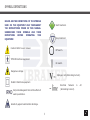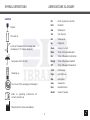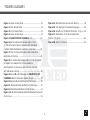
1
Instruction Manual
NEURODYN
10 CHANNELS
Manufactured by
Ibramed - Indústria Brasileira de Equipamentos Médicos EIRELI
Made in Brazil
rd
10 edition (12/2012) Anvisa nº 10360310023
TABLE OF CONTENTS
SYMBOL DEFINITIONS.................................................3
CARTON ............................................................4
ABREVIATIONS GLOSSARY...........................................4
FIGURES GLOSSARY....................................................5
FOREWORD................................................................6
PRODUCT DESCRIPTION . ............................................6
SAFETY PRECAUTIONS.................................................7
PRECAUTIONARY DEFINITIONS.............................7
ELECTROTHERAPY INDICATIONS,
CONTRAINDICATIONS, PRECAUTIONS
AND ADVERSE REACTIONS...........................................9
SPECIFICATIONS.......................................................23
SYSTEM SPECIFICATIONS...................................23
ACCESSORIES USED .........................................26
OPERATING INSTRUCTIONS .......................................27
PROGRAMMING EQUIPMENT ......................................28
ELECTRODE GUIDELINE ............................................30
ELECTROTHERAPY PATIENT
PREPARATION...................................................30
ELECTRODE POSITIONING..................................30
USING THE PROG/MENU BUTTON................................34
USING THE MENU BUTTON..................................34
USING THE PROG BUTTON..................................34
CLINICAL RESOURCES LIBRARY -
INDICATIONS FOR USE........................................9
CONTRAINDICATIONS..........................................10
WARNINGS.........................................................10
PRECAUTIONS.....................................................10
ADVERSE REACTIONS .........................................11
GENERAL EQUIPMENT CARE..........................................11
SHIPPING DAMAGE..............................................11
INSTALLATION, CARE AND CLEANING.....................11
Electromagnetic Compatibility Guidance.......12
ELETROMAGNECTIC COMPATIBILITY..............................13
NOMENCLATURE..........................................................19
CONTROLS, INDICATORS AND
CONNECTIONS....................................................19
SYMBOL DEFINITIONS.................................................20
2
CLINICAL PROTOCOLS...............................................35
REFERENCES............................................................38
ACCESSORIES ACCOMPANYING
NEURODYN 10 CHANNELS..........................................51
TROUBLESHOOTING..................................................53
MAINTENANCE, WARRANTY AND
TECHNICAL SUPPORT.................................................53
MAINTENANCE..................................................53
WARRANTY.......................................................53
WARRANTY TERMS.............................................54
TECHNICAL ASSISTANCE ...................................55
CEFAI – IBRAMED Center for
Education and Advanced Training.................................56
SYMBOL DEFINITIONS
BELOW ARE THE DEFINITIONS OF THE SYMBOLS
USED ON THE EQUIPMENT AND THROUGHOUT
THE INSTRUCTIONS FOUND IN THIS MANUAL.
UNDERSTAND THESE SYMBOLS AND THEIR
DEFINITIONS
BEFORE
OPERATING
THIS
EQUIPMENT.
Start treatment.
Stop treatment.
Caution! Refer to user manual.
Off switch.
TYPE BF Electrical equipment.
On switch.
Dangerous voltage.
Voltage in AC (Alternating Current).
CLASS II Electrical equipment.
Electrical
Network
(Alternating Current).
Not protected against the harmful effects of
water penetration.
Sensitivity against electrostatic discharge.
3
in
AC
SYMBOL DEFINITIONS
ABREVIATIONS GLOSSARY
CARTON
Fragile.
This side up.
Limits of temperature for storage and
packaging in °C (Celsius Degrees).
Keep away from the rain.
Stacking up.
Do not use if the packaging is damaged.
Refer to operating
correct product use.
instructions
for
Manufacturer’s name and address.
4
Hz
Hertz (pulses per second)
kHz
Kilohertz
mA
Milliampere
VA
Volt Ampere
ms
Miliseconds
kg
kilograms
Russ
Russian Current
Rise
Time of Increase Gradient
On
Time of Muscular Contraction
Decay
Time of Decrease Gradient
Off
Time of Muscular Relaxation
Cont
Continuous
Sync
Synchronous
Rec
Reciprocal
Seq
Sequential
Des
Desobstruction
Burst
Series of pulses
FIGURES GLOSSARY
Figure 1. Upper Access Panel......................................19
Figure 2. Rear Access Panel .......................................19
Figure 3. Front Access Panel.......................................19
Figure 4. Lower Access Panel......................................19
Figure 5. NEURODYN 10 CHANNELS LCD..................20
Figure 6. A. Pin cables with banana ends (2 mm)
(in the same cable has two channels with individual
controls); B. Self-adhesive conductive electrodes. .........26
Figure 7. Pens for facial stimulation with conductive
electrodes on the tips ................................................26
Figure 8. Pin cables with banana ends (2 mm) connected
to alligator clip adapters to fix the needles to
electrolypolisis (in the same cable has two channels
with individual controls)..............................................26
Figure 9. A. and B. LCD Messages; C. NEURODYN 10
CHANNELS Electro Stimulator Default Screen................27
Figure 10. Bipolar Electrode Placement Technique...........30
Figure 11. Monopolar Electrode Placement Technique........31
Figure 12. Facial Electrode Placement Technique..............31
Figure 13. A. Electrolypolisis Electrode-Needles Placement
Technique..................................................32
Figure 14. Electrode sizes and current density.............33
Figure 15. LCD displays the selected language............34
Figure 16. Selection of Treatment Protocols - Prog 1....34
Figure 17. Parameters of the Pre-Programmed
Protocol 1 Program...................................................34
Figure 18. User 01 Protocol......................................35
5
FOREWORD
PRODUCT DESCRIPTION
This user manual allows the user to efficiently use the
NEURODYN
NEURODYN 10 CHANNELS Electro Stimulator. It also
neuromuscular stimulator is a ten-channel stimulator
gives suggestions for treatment protocols so that you
with independent controls for current therapies used in:
can use your equipment to its full potential.
RUSSIAN
Consult other resources for additional information
Frequency) and AUSSIE CURRENT (Burst Modulated
regarding the uses of electrotherapy before attempting
Medium Frequency).
10
CURRENT
CHANNELS
(Burst
transcutaneous
Modulated
Medium
any treatment on a patient. Users must read, understand
and follow the information in this manual for each
Treatment should be administered only under the direct
mode of treatment available, as well as the indications,
supervision of a health care professional.
contraindications, warnings and precautions.
The specifications and instructions in this manual are in
effect at the time of its publication. These instructions
may be updated at any time at the manufacturer’s
discretion. Visit our website for updates.
6
SAFETY PRECAUTIONS
PRECAUTIONARY DEFINITIONS
The precautionary instructions found in this section and
throughout this manual are indicated by specific symbols.
• Read, understand, and practice the precautionary and
Understand these symbols and their definitions before
operating instructions. Know the limitations and hazards
operating this equipment prior to therapy session.
associated with the use of any electrical stimulation.
Observe the precautionary and operational labels placed
on the unit.
Text with a “CAUTION” indicator refers to potential safety
• DO NOT operate this unit in an environment where other
infractions that could cause minor to moderate injury or
devices intentionally radiate electromagnetic energy in
damage to equipment.
an unshielded manner.
• Check cables and associated connectors before each
use.
Text with a “WARNING” indicator refers to potential
• The NEURODYN 10 CHANNELS Electro Stimulator is
safety infractions that could cause serious injury and
not designed to prevent the infiltration of water or other
equipment damage.
liquids. The infiltration of water or other liquids could
cause malfunction of internal components of the system
and therefore create a risk of injury to the patient.
• Disconnect the power plug from the outlet when left
Text with a “DANGER” indicator refers to potential safety
unused for long periods of time.
infractions that represent immediately life threatening
situations that would result in death or serious injury.
7
SAFETY PRECAUTIONS
• Stimulation should not be applied over the anterior neck
or mouth.
• Severe spasm of the laryngeal and pharyngeal muscles
• To protect against the risk of fire, only use replacement
may occur and the contractions may be strong enough
fuses of the same types and ratings.
to close the airway or cause breathing difficulties.
• Be sure the unit is grounded by connecting it to a
• Stimulation should not be applied transthoracically to
grounded electrical outlet compliant with the applicable
avoid the introduction of electrical current into the heart
national and local electrical codes.
which may cause cardiac arrhythmia.
• Powered muscle stimulators should be used only with
• Stimulation should not be applied over swollen, infected,
the lead wires and electrodes recommended for use by
and inflamed areas or skin eruptions such as phlebitis,
the manufacturer.
thrombophlebitis, varicose veins, etc.
• Prior to patient treatment become familiar with the
• Stimulation should not be applied on or near cancerous
operating procedures for each mode of treatment
lesions.
available, as well as the indications, contraindications,
• Output current density depends on the electrode size.
warnings and precautions. Consult other resources for
Improper application may result in patient injury. For any
additional information regarding the applications of
question related to the correct electrode size, consult a
• Electrotherapy.
licensed practitioner prior to therapy session.
To prevent electrical shock, disconnect the unit from the
• power source before performing any maintenance task.
Keep electrodes separated during treatment. Electrodes
in contact with each other could result in improper
stimulation or skin burns.
8
INDICATIONS, CONTRAINDICATIONS,
PRECAUTIONS AND ADVERSE REACTIONS
SAFETY PRECAUTIONS
INDICATIONS FOR USE
Indications for Russian and Aussie
(1 kHz/2 ms) waveforms
• Patients with an implanted neurostimulation device must
• Relaxation of muscle spasms.
not be treated with or be in close range of any shortwave
Prevention or retardation of disuse atrophy.
diathermy, microwave diathermy, therapeutic ultrasound
diathermy
or
laser
diathermy
anywhere
on
• Increase local blood circulation.
their
Muscle re-education.
body. Energy from diathermy (shortwave, microwave,
Maintaining or increasing range of motion.
ultrasound and laser) can be transferred through the
implanted neurostimulation system, can cause tissue
damage, and can result in severe injury or death. Injury,
Additional Indications for Aussie
(4 kHz/4 ms) waveform
damage or death can occur during diathermy therapy
• Symptomatic relief and management of chronic intractable
even if the implanted neurostimulation system is powered
pain.
“off.”
• Increase local blood circulation.
• Post-traumatic acute pain.
• It is not envisaged the use of these units in places where
• Post-surgical acute pain.
risk of explosion, such as departments anesthesia or in
the presence of an anesthetic mixture flammable with
Indications for Electrolipolysis
air, oxygen or nitrous oxide.
• Stimulation of lipolysis in the treatment of fat located.
• Temporary reduction in the appearance of cellulite.
• Temporary improvement of local blood circulation.
9
INDICATIONS, CONTRAINDICATIONS,
PRECAUTIONS AND ADVERSE REACTIONS
INDICATIONS, CONTRAINDICATIONS,
PRECAUTIONS AND ADVERSE REACTIONS
CONTRAINDICATIONS
WARNINGS
• Powered muscle stimulators should not be used on patients
• Stimulation should not be applied over the neck or mouth.
with cardiac demand pacemakers.
• Severe spasm of the laryngeal and pharyngeal muscles
• This device should not be used for symptomatic local
may occur and the contractions may be strong enough to
pain relief unless etiology is established or unless a pain
close the airway or cause breathing difficulties.
syndrome has been diagnosed.
• Stimulation should not be applied transthoracically to
• Other contraindications include patients suspected of
avoid the introduction of electrical current into the heart
carrying infectious diseases and/or disease where it is
which may cause cardiac arrhythmias.
advisable for general medical purposes to suppress heat or
• Stimulation should not be applied transcerebrally.
fevers.
• Stimulation should not be applied over swollen, infected,
or inflamed areas or skin eruptions, such as phlebitis,
thrombophlebitis, varicose veins, etc.
WARNINGS
• Stimulation should not be applied on or near cancerous
• The long-term effects of chronic electrical stimulation are
not known.
lesions.
• Stimulation should not be applied in the presence of
• Stimulation should not be applied over the carotid sinus
electronic control equipment (eg, heart monitors, ECG
nerves, particularly in patients with a known sensitivity to
alarms), which can not work properly when the device
the carotid sinus reflex.
electrical stimulation is in use.
• Stimulation should not be applied when the patient is in
the bath or shower.
10
INDICATIONS, CONTRAINDICATIONS,
PRECAUTIONS AND ADVERSE REACTIONS
INDICATIONS, CONTRAINDICATIONS,
PRECAUTIONS AND ADVERSE REACTIONS
PRECAUTIONS
c. Over the menstruating or pregnant uterus; and
d. Over areas of the skin which lack normal sensation.
• Stimulation should not be applied while the patient is
• Some patients may experience skin irritation or
hypersensitivity caused by the electrical stimulation or
electrical conductive medium. The irritation can usually
be reduced by using an alternate conductive medium or
alternate electrode placement.
sleeping.
• Stimulation should not be applied while the patient is
driving, operating machinery, or during any activity in
which electrical stimulation can putting the patient at risk
of injury.
• Electrode placement and stimulation settings should be
based on the guidance of the prescribing practitioner.
• Consult the patient’s physician before using this device
• Powered muscle stimulators should be kept out of the
reach of children.
because the device may cause disturbances lethal rhythm
cardiac individuals.
• Powered muscle stimulators should be used only with
the lead wires and electrodes recommended by the
manufacturer.
• The stimulation should be applied only in normal skin,
intact, clean and healthy.
• Safety of powered muscle stimulators for use during
pregnancy has not been established.
ADVERSE REACTIONS
• Caution should be used for patients with suspected or
• Skin irritation and burns beneath the electrodes have been
diagnosed heart problems.
reported with the use of powered muscle stimulators.
• Caution should be used for patients with suspected or
• Patients may experience headaches and other sensations
diagnosed epilepsy.
pain during or after application of stimulation electric near
Caution should be used in the presence of the following:
a. When there is a tendency to hemorrhage following acute
trauma or fracture;
b. Following recent surgical procedures when muscle
the eyes, head and face.
contraction may disrupt the healing process;
use of the device.
• Patients should stop using the appliance and should
consult their therapists feel the adverse reactions from the
11
GENERAL CARE WITH THE EQUIPMENT
SHIPPING DAMAGE
INSTALLATION, CARE AND CLEANING
Your NEURODYN 10 CHANNELS Electro Stimulator is
Installation instructions
shipped complete in one carton. Upon receipt, inspect
1. Connect the line cord to the back of the NEURODYN
10 CHANNELS Electro Stimulator.
2. Plug the line cord into a grounded wall outlet (100/240V
- 50/60 Hz).
3. Plug the electrode cables into the electrode cable
connections.
4. Switch on your equipment.
carton and unit for visible and hidden damage. In case of
damage, keep all shipping materials including carton and
contact the shipping agent responsible for the delivery of
the unit. All claims relating to damage during transport
should be filed directly with them. The manufacturer will
not be liable for any damage during shipping, nor allow
for adjustments unless proper formal claim has been filed
by the receiver against the carrier. The carton in which
Electro Stimulator Care Instructions
your NEURODYN 10 CHANNELS Electro Stimulator was
received is specially designed to protect the unit during
• Avoid areas subject to vibrations.
Install the equipment on a firm and level surface, in open
air.
• Do not block ventilation.
• Avoid humid, hot and dusty environments.
• Make sure the area around the network cable is free.
• Do not insert objects into device holes.
shipping. Please keep all shipping materials in case you
need to return your unit for servicing.
12
GENERAL CARE WITH THE EQUIPMENT
Cleaning the NEURODYN 10 CHANNELS Electro
Stimulator
Disconnect the system from the power source, wipe with
a clean, lint free cloth moistened with water and mild
antibacterial soap. If a more sterile cleaning is needed,
use a cloth moistened with an antimicrobial cleaner. Do
not place the system in liquids.
THE DEVICE AND PARTS CONSUMABLES
BE ELIMINATED, THE END OF LIFE
USEFUL IN ACCORDANCE WITH FEDERAL
STANDARDS AND /
OR STATE AND / OR LOCAL COUNTRY.
Environmental protection
NEURODYN 10 CHANNELS is an electronic device
and
has
heavy
metals
such
as
lead.
Thus,
there are risks of contamination to the environment
associated with the disposal of this equipment and its
accessories at the end of their useful lives. NEURODYN
10 CHANNELS, parts and accessories should not be
disposed of as waste. Contact the distributor
site for information on rules and laws concerning
disposal of waste electrical electronic equipment
and its accessories.
13
ELECTROMAGNETIC COMPATIBILITY GUIDANCE
• It is not envisaged the use of this unit where there is risk of explosion such as anesthesia departments or
presence of a flammable anesthetic mixture with air, oxygen or nitrous oxide.
• Using cables, electrodes and other accessories from other manufacturers and / or different from those specified herein
and replacement of internal components NEURODYN 10 CHANNELS may result in increased emissions or decreased
immunity of the equipment.
• NEURODYN 10 CHANNELS, is intended for use only by health care professionals. NEURODYN 10 CHANNELS, may
cause radio interference or disrupt equipment operations nearby. It may be necessary adopt mitigation procedures, such
as reorienting or relocating the equipment or shielding the location.
• RF communication equipment, mobile or portable, can cause interference and affect the functioning of NEURODYN
10 CHANNELS.
14
ELETROMAGNECTIC COMPATIBILITY
NEURODYN 10 CHANNELS is an electromedical equipment that belongs to Group 2 Class A. Electromedical devices require
special attention in relation to electromagnetic compatibility (EMC) and must be installed and operated in accordance with the
EMC information provided in the following tables:
Guidance and Manufacturer’s Declaration - Electromagnetic Emissions
The NEURODYN 10 CHANNELS is intended for use in the electromagnetic environment specified below. The
customer or the user of the NEURODYN 10 CHANNELS should ensure that it is used in such an environment.
Emission Test
Compliance
RF Emissions
CISPR 11
Group 1
RF Emissions
CISPR 11
Class B
Harmonic
Emissions
IEC 61000-3-2
Applicable
Voltage fluctuations/
flicker emissions
IEC 61000-3-3
Applicable
Electromagnetic environment - Guidance
The NEURODYN 10 CHANNELS must emit
electromagnetic energy in order to perform it’s intend
function. Nearby electronic equipment may be affected.
The NEURODYN 10 CHANNELS is suitable for use in
all establishments other than domestic those directly
connected to the public low-voltage power supply network
that supplies buildings used for domestic purposes.
15
ELETROMAGNECTIC COMPATIBILITY
Guidance and Manufacturer’s Declaration - Electromagnetic Immunity
The NEURODYN 10 CHANNELS is intended for use in the electromagnetic environment specified below. The
customer or the user of the NEURODYN 10 CHANNELS should assure that it is used in such an environment.
IEC 60601
Test Level
Immunity Test
Electrostatic
discharge (ESD)
IEC 61000-4-2
Electrical fast
transitory/burst
IEC 61000-4-4
Surge
IEC 61000-4-5
Compliance Level
+6
-
kV by contact
+ 8 kV by air
-
+6
-
+2
-
kV for power
supply lines
+ 1 kV for input/
output lines
+2
-
+1
-
+1
-
kV diferencial
mode
+ 2 kV common
mode
kV by contact
+ 8 kV by air
-
kV for power
supply lines
+ 1 kV for input/
output lines
kV diferencial
mode
+ 2 kV common
mode
16
Electromagnetic Environment - Guidance
Floors should be wood, concrete or ceramic tile.
If floors are covered with synthetic material, the
relative humidity should be at least 30%.
Mains power quality should be that of a typical
commercial or hospital environment.
Mains power quality should be that of a typical
commercial or hospital environment.
ELETROMAGNECTIC COMPATIBILITY
Guidance and Manufacturer’s Declaration - Electromagnetic Immunity
The NEURODYN 10 CHANNELS is intended for use in the electromagnetic environment specified below. The
customer or the user of the NEURODYN 10 CHANNELS should assure that it is used in such an environment.
Immunity Test
Voltage dips,
short interruptions
and voltage
variations in
power input lines
IEC 61000-4-11
Power frequency
(50/60 Hz)
magnetic fild
IEC 60601
Test Level
Compliance Level
< 5% UT
(> 95% voltage drops
in UT ) 0.5 by cycle
< 5% UT
(> 95% voltage drops
in UT )by 0,5 ciclo
40% UT voltage drops
in
(60% UT ) by 5 cycles
40% UT
(60% de voltage drops
in UT )by 5 cycles
70% UT
(30% voltage drops in
UT ) by 25 cycles
70% UT
(30% voltage drops in
UT ) by 25 cycles
< 5% UT
(> 95% voltage drops
in UT ) by 5 seconds
< 5% UT
(> 95% voltage drops
in UT ) by 5 seconds
3 A/m
Electromagnetic Environment - Guidance
Mains power quality should be that of a typical
commercial or hospital environment. If the
user of the NEURODYN 10 CHANNELS
requires continued operation during power
mains interruptions, it is needed that the
NEURODYN 10 CHANNELS be powered from
an uninterruptible power supply or battery.
Power frequency magnetic fields should be at
levels characteristic of a typical location in a
typical commercial or hospital environment.
3 A/m
IEC 61000-4-8
NOTE: UT is the A.C. mains voltage prior to applications of the test level.
17
ELETROMAGNECTIC COMPATIBILITY
Guidance and Manufacturer’s Declaration - Electromagnetic Immunity
The NEURODYN 10 CHANNELS is intended for use in the electromagnetic environment specified below. The
customer or the user of the NEURODYN 10 CHANNELS should assure that it is used in such an environment.
Immunity Test
IEC 60601
Test Level
Compliance
Level
Electromagnetic Environment - Guidance
Portable and mobile RF communication equipment should
not be used no closer to any part of NEURODYN 10
CHANNELS, including cable than be separation distance
calculated from the equation applicable to the frequency of
the transmitter.
3 Vrms
150 kHz to 80 MHz
Conducted RF
IEC 61000-4-6
Radiated RF
IEC 61000-4-3
Recommended separation distance
d = 1.2 P
d = 1.2 P 80 MHz to 800 MHz
d = 2.3 P 800 MHz to 2.5 GHz
3V
10 V/m
80 MHz to 2.5 GHz
10 V/m
Where p is the maximum output power rating of the
transmitter in watts (W) according to the transmitter
manufacturer and d is the recommended separation
distance in meters (m).
Field strengths from fixed RF transmitters, as determined
by an electromagnetic site survey,a should be less than the
compliance level in each frequency range.b
18
ELETROMAGNECTIC COMPATIBILITY
Guidance and Manufacturer’s Declaration - Electromagnetic Immunity
The NEURODYN 10 CHANNELS is intended for use in the electromagnetic environment specified below. The
customer or the user of the NEURODYN 10 CHANNELS should assure that it is used in such an environment.
Immunity Test
IEC 60601
Test Level
Compliance
Level
Conducted RF
IEC 61000-4-6
3 Vrms
150 kHz to 80 MHz
3V
Radiated RF
IEC 61000-4-3
10 V/m
80 MHz to 2.5 GHz
10 V/m
Electromagnetic Environment - Guidance
Interference may occur in the vicinity of equipment
marked with the following symbol:
NOTE 1: At 80 MHz and 800 MHz the higher frequency range applies.
NOTE 2: These guidelines may not apply in all situations. Electromagnetic propagation is affected by absorption and
reflection from structures, objects and people.
Field strengths set by fixed transmitters, such as radio base stations, telephone (cellular/cordless) telephones and land mobile
radios, amateur radio, AM / FM radio broadcast and TV broadcast cannot be predicted theoretically with accuracy. To assess the
electromagnetic environment due to fixed RF transmitters, an electromagnetic site survey should be considered. If the measured
field strength at the location in which the NEURODYN 10 CHANNELS is used exceeds the applicable RF compliance level above,
the NEURODYN 10 CHANNELS should be observed to verify normal operation. If abnormal performance is observed, additional
measures may be necessary, such as reorientation or relocating the NEURODYN 10 CHANNELS.
a
b
Over the frequency range 150 kHz to 80 MHz, field strengths should be less than 10 V/m.
19
ELETROMAGNECTIC COMPATIBILITY
Recommended separation distances between the mobile RF communication equipment and NEURODYN 10 CHANNELS
The NEURODYN 10 CHANNELS is intended for use in an electromagnetic environment in which radiated RF disturbances are
controlled. The customer or the user of the NEURODYN 10 CHANNELS can help prevent electromagnetic interference by
maintaining a minimum distance between portable and mobile RF communications equipment (transmitters) and the NEURODYN
10 CHANNELS as recommended below, according to the maximum output power of the communications equipment.
Rated maximum power
output of transmitter
w
Separation distance according to frequency of transmitter
m
150 KHz to 80 MHz
d = 1.2
80 MHz to 800 MHz
P
d = 0.35
P
800 MHz to 2.5 GHz
d = 0.7
P
0.01
0.12
0.035
0.07
0.1
0.38
0.11
0.22
1
1.2
0.35
0.7
10
3.8
1.1
2.2
100
12
3.5
7
For transmitters rated at a maximum output power not listed above, the recommended separation distance d in meters
(m) can be estimated using the equation applicable to the frequency of the transmitter, where P is the maximum output
power rating of the transmitter in watts (W) according to the transmitter manufacturer.
NOTE 1: 80 MHz to 800 MHz, the separation distance for the higher frequency range applies.
NOTE 2 These guidelines may not apply in all situations. Electromagnetic propagation is affected by absorption and
reflection from structures, objects and people.
20
NOMENCLATURE
CONTROLS, INDICATORS AND CONNECTIONS
1- Power ON/OFF Switch.
2- Power On Indicator LED.
3- BACK/NEXT Buttons.
4- SET + /SET - Buttons.
5- LED Display.
6- START/STOP.
7- PROG/MENU Button. PROG: Clinical
Resources Library; MENU: Select Language.
8- Channel indicator LEDs
9- UP/DOWN Buttons.
Figure 1. Upper Access Panel.
21
NOMENCLATURE
Figure 2. Rear Access Panel.
Figure 4. Lower Access Panel.
10- Channel Lead Wire Connectors.
11- Line Cord Connection.
12- Fuse.
13- General Technical Information.
Figure 3. Front Access Panel.
14- Current output Label characteristics.
15 - Serial Number.
16 - Federal Law (USA).
22
SYMBOL DEFINITIONS
Read and Understand these symbols and their definitions before operating this equipment.
Before using and operating the NEURODYN 10 CHANNELS Electro Stimulator, please read and learn the symbols on the
LCD device (Figure 5).
Figure 5. NEURODYN 10 CHANNELS LCD.
23
SYMBOL DEFINITIONS
Russian Current (Russ. and Electrolypolisis)
Aussie Current (Aussie)
Time of Decrease Gradient: Russian Current
and Aussie Current: 1 to 20 seconds.
Cont.: Continuous; Sync.: Synchronous; Seq.:
Sequential; Rec.: Reciprocal;
Des.: Desobstruction.
Time of Muscular Relaxation: Russian Current
and Aussie Current: 1 to 60 seconds.
Treatment Time: 1 to 60 minutes.
Burst Duration Aussie Current: 2 ms or 4 ms.
Burst Duration Russian Current: 50%.
Burst Frequency Aussie Current: 1 Hz to 120 Hz.
Burst Frequency Russian Current: 1 Hz to 120 Hz.
Channels 1 and 2 Lead
Wire Connectors.
Channels 3 and 4 Lead
Wire Connectors.
Carrier Frequency Aussie Current: 1 kHz or 4 kHz.
Channels 5 and 6 Lead
Wire Connectors.
Time of Increase Gradient: Russian Current
and Aussie Current: 1 to 20 seconds.
Channels 7 and 8 Lead
Wire Connectors.
Time of Muscular Contraction: Russian Current
and Aussie Current: 1 to 60 seconds.
Channel 9 and 10 Lead
Wire Connectors.
24
SYMBOL DEFINITIONS
Button used to start or stop the
treatment. Always press the
center key.
Move Next
Move Back
Dual function Button: PROG
selection of pre-programmed
protocols
(20
programs)
or
programming
of
new
protocols;
MENU - function
menu
to
select
language
(Portuguese, English or Spanish).
Parameters increase
Parameters decrease
Up or Down Intensity: Channels 1, 2, 3, 4, 5, 6, 7, 8, 9 and 10. Observe the colors related to channels.
Note the colors related to channels.
25
SPECIFICATIONS
SYSTEM SPECIFICATIONS
Regulatory Compliance
Dimensions
Width:
17.5 cm (6.8’’ in)
Depth:
31.5 cm in (12.40’’)
Height:
12.5 cm (4.8” in)
Standard Weight
(without accessories):
2.5 kg
IEC 60601-1
IEC 60601-1-2
IEC 60601-2-10
Temperature Range During Transport and
Storage: Between 55 - 50 °C / 59 and 104°F.
Power
Input:
100 / 240V~
Input Power:
85 VA
Fuses:
5A
Electrical Class:
CLASS II
Electrotherapy:
TYPE BF
250V~
Environment operating temperature range:
50/60 Hz
5 - 45 °C/ 41- 113 °F.
(20AG)
26
SPECIFICATIONS
WAVEFORM SPECIFICATIONS
Output Mode: Electrodes
Russian Current
Output Intensity: 0-140 mA
Russian Current is a medium frequency alternating current
Current Mode
(2.5 kHz) modulated bursts with rectangular frequency 50
CNT: Continuous (1, 2, 3, 4, 5, 6, 7, 8, 9 &10 channels)
Hz and a duty cycle of 50% is used to produce muscle
SYN: Synchronous (1, 2, 3, 4, 5, 6, 7, 8, 9 &10 channels)
strengthening.
REC: Reciprocal (1, 2, 3, 4, 5 & 6, 7, 8, 9, 10 channels)
SEQ: Sequential (1, 2, 3, 4, 5, 6, 7, 8, 9 &10 channels)
DES: Desobstruction (1, 2, 3, 4, 5, 6, 7, 8, 9 &10 channels)
Burst Duration: 50%
Burst Frequency: 1-120 Hz
Ramp
Rise (Time of Increase Gradient): 1-20 s
On (Time of Muscular Contraction): 1-60 s
Decay (Time of Decrease Gradient): 1-20 s
Off (Time of Muscular Relaxation): 1-60 s
Treatment Time: 1-60 min
Set Intensity: Individual Channel Intensity Setting
Available on Channels: 1, 2, 3, 4, 5, 6, 7, 8, 9 or 10 Option
27
SPECIFICATIONS
Aussie Current
The Aussie current (Australian current) is a medium frequency
alternating current released in short bursts (1 kHz / burst duration
of 2 ms or 4 kHz / burst length of 4 ms) used to produce maximum
muscle torque or analgesia respectively.
Output Mode: Electrodes
Output Intensity: 0-140 mA
Current Mode
CNT: Continuous (1, 2, 3, 4, 5, 6, 7, 8, 9 &10 channels)
SYN: Synchronous (1, 2, 3, 4, 5, 6, 7, 8, 9 &10 channels)
REC: Reciprocal (1, 2, 3, 4, 5 & 6, 7, 8, 9, 10 channels)
SEQ: Sequential (1, 2, 3, 4, 5, 6, 7, 8, 9 &10 channels)
DES: Desobstruction (1, 2, 3, 4, 5, 6, 7, 8, 9 &10 channels)
Burst Duration: 2 or 4 ms
Carrier Frequency: 1 or 4 kHz
Burst Frequency: 1-120 Hz
1 kHz/2 ms
Ramp
Rise (Time of Increase Gradient): 1-20 s
On (Time of Muscular Contraction): 1-60 s
Decay (Time of Decrease Gradient): 1-20 s
Off (Time of Muscular Relaxation): 1-60 s
Treatment Time: 1-60 min
Set Intensity: Individual Channel Intensity Setting
Available on Channels: 1, 2, 3, 4, 5, 6, 7, 8, 9 or 10 Option
4 kHz/4 ms
28
ACCESSORIES USED
RUSSIAN CURRENT and AUSSIE CURRENT: pin connector
cables with banana ends (2 mm) and conductive rubber
electrodes and neutral gel (Figure 6).
ELECTROLIPOLYSIS
A
B
Figure 8. Pin cables with banana ends (2 mm) connected to
alligator clip adapters to fix the needles to electrolypolisis (in
the same cable has two channels with individual controls).
C
Figure 6. A. Pin cables with banana ends (2 mm) (in the
same cable has two channels with individual controls); B.
Conductive electrodes.
The connector screws must be firmly affixed to your
connection on the back panel of the device.
To remove the electrodes conductive rubber pins banana is
required to pull them by their protective cover, never pull
the cord.
Figure 7. Pens for facial stimulation with conductive
electrodes on the tips.
29
OPERATING INSTRUCTIONS
Note that entering the default screen will cause the word
Russ. to flash. This is to do with the ‘selection cursor
parameters’ function which displays whenever the device
is being programmed.
Prepare Device
Turn the power switch. LCD displays the message device
presentation for a few seconds, followed by the software
model of the device default screen programming (Figure 9).
Edit Waveform Parameters
A.
The BACK/NEXT buttons allow you to select the parameters
required for the treatment. Press the NEXT button for the
cursor to move to the next parameter. Press the BACK button
for the cursor to move back to the previous setting.
The SET + / SET - buttons allow you to select the values
of each parameter required for the treatment.
B.
Select Waveform
Press SET + or SET - to select the device waveform you
want to use for the treatment: RUSSIAN CURRENT (Burst
Modulated Medium Frequency) or AUSSIE CURRENT (Burst
Modulated Medium Frequency).
C.
Time Parameters
Set the session time. At the end of the scheduled time, you
will hear a beep indicating that the emission current has been
interrupted. Press the STOP button, the sound signal turns
Figure 9. A. and B. LCD Messages; C. NEURODYN 10
CHANNELS Electro Stimulator Default Screen.
30
OPERATING INSTRUCTIONS
PROGRAMMING EQUIPMENT
off and the equipment goes back to the programming
status.
Example: Suppose that to treat a specific pathology,
you need to select the following parameters:
Current Type: Aussie (Aussie Current)
Current Mode: Sync. (Synchronous)
Carrier Frequency = 1 kHz
Burst frequency = 60 Hz
Burst Duration= 4 ms
Rise= 3 s
On= 2 s
Decay= 2 s
Off= 5 s
Treatment time= 15 min
Prepare and Install Patient Switch
Prepare the patient for therapy as described and read
about the use of electrodes.
Start Treatment:
Press the START button to begin
therapy session.
Stop Treatment:
1. Connect the equipment to start programming the
pattern described above. Note the blinking cursor in the
CURRENT TYPE field.
Press the STOP button to end
therapy session.
Waveform Intensity
The Waveform Intensity may be increased or decreased at
any time during the session. Press the INTENSITY button
up or down.
31
PROGRAMMING EQUIPMENT
3. With the NEXT/BACK and SET + / SET - keys, scroll
through the other parameters and select the values shown
in the example.
2. Press the SET + button until Aussie (Aussie Current)
displays, as shown below:
4. Now press the START button to start treatment. Note
that the “flashing” cursor disappears while the LDC display
now shows the intensity.
6. At the end of the programmed time, the emission
current is interrupted and an audible alarm will signal
the treatment end.
5. Press the UP or DOWN channel in use to select the
amount of current needed to treat.
7. Press the STOP button to stop the alarm. The equipment can now be switched off, repeat the same programming task, or undertake a new programming task.
32
ELECTRODE GUIDELINE
ELECTROTHERAPY PATIENT PREPARATION
are placed at each end of the muscle or muscle group.
The symmetrical waveforms of the Biphasic and Medium
Frequency are usually applied to the body using the Bipolar
Technique. The NEURODYN 10 CHANNELS Electro
Stimulator offers waveforms of the RUSSIAN CURRENT
and AUSSIE CURRENT.
• Electrode Placement can be achieved using the Bipolar
or Monopolar Techniques. Proper positioning and contact
will insure treatment comfort and efficiency.
• Examine the skin for any wounds and clean the treatment
area by rubbing the skin with medical grade alcohol.
• Before placing the electrodes, clean the area with soft soap
and water to remove oil and possible skin fragments, thus
reducing the resistance to the passage of the electrical
current. Rinse and dry the area well before placing the
electrodes.
• Remove the self-adhesive electrodes from the protective
backing and apply to the treatment area as prescribed.
• Ensure the entire electrode surface is in contact with
patient skin by pressing into place.
• Check the electrode contact regularly during treatment.
• Examine the skin again after the treatment.
Figure 10. Bipolar Electrode Placement Technique.
ELECTRODE POSITIONING
Monopolar Electrode Placement Technique
Bipolar Electrode Placement Technique
The Monopolar Electrode Placement
found to be especially useful for
of the upper extremities and small
smaller electrode is placed over
Bipolar Electrode Placement Techniques should be used
to provide stimulation to larger muscle groups, such as
the quadriceps or the hamstrings. Equal size electrodes
33
Technique has been
muscle stimulation
muscle groups. The
the muscle motor
ELECTRODE GUIDELINE
point and the larger electrode is placed over the painful
area. Monopolar Techniques may be used with the
Waveforms Symmetrical Biphasic and Medium Frequency.
The NEURODYN 10 CHANNELS Electro Stimulator offers
Waveforms of the RUSSIAN CURRENT and AUSSIE
CURRENT.
or muscle group. The symmetrical waveforms of the
Biphasic and Medium Frequency are usually applied to
the face using the Facial Technique. The NEURODYN
10 CHANNELS Electro Stimulator offers waveforms
of the RUSSIAN CURRENT and AUSSIE CURRENT.
Figure 11. Monopolar Electrode Placement Technique.
Figure 12. Facial Electrode Placement Technique.
Facial Electrode Placement Technique
Electrolypolisis Electrode-Needles Placement
Technique
Facial Electrode Placement Techniques should be
used to provide stimulation to facial muscles groups.
Electrodes are placed at each end of the muscle
The NEURORYN 10 CHANNELS offers the possibility
34
ELECTRODE GUIDELINE
subcutaneous stimulator for treatment with Electrolipolysis
for treatment of localized fat (Aesthetics Medicine)
and Electro-Acupuncture (Practice of Medicine Chinese
Acupuncture). We suggest Vinco Brand Acupuncture
B.
A.
Figure 13. A. Electrolypolisis and B. Electro-Acupuncture Electrode-Needles Placement Technique.
Placement of the electrodes near the chest may increase the risk of cardiac fibrillation.
35
ELECTRODE GUIDELINE
Electrode Sizes and Current Density
The size of the electrodes and the energy density used during therapy must comply with IEC 60601-2-10, i.e., the current
density per area of electrode should not exceed 2 mA/cm2. Follow the manufacturer’s instructions.
We recommend the use of electrodes provided by Axelgaard Manufacturing Co., Ltd. Fallbrook, CA 92028, USA. FAX +1 (760)
723 2356. www.axelgaard.com.
Figure 14. Electrode sizes and current density.
36
USING THE PROG/MENU BUTTON
USING THE MENU BUTTON
The PROG/MENU button is used to select the language.
Press PROG/MENU until you hear three “beeps.” Select
the desired language: ‘Português’, ‘Español or ‘English’
(Figure 15). Short press PROG/MENU to set the chosen
language.
Figure 16. Selection of Treatment Protocols - Prog 1.
If this is the protocol chosen, press the PROG key once
again. The LCD displays the parameters of the equipment
scheduled for the selected protocol (Figure 17). Then simply
press the START button and select the desired current
density.
Proceed the same way to select any of the 8 protocols
available. Simply follow the steps above.
Figure 15. LCD displays the selected language.
USING THE PROG BUTTON
Connect the equipment as described above. Briefly press
PROG and the following information will appear on the LCD
(Figure 16). This is the first equipment to offer a choice of
Treatment Protocols. Use the SET + / SET - buttons to
select another protocol.
Figure 17. Parameters of the Pre-Programmed Protocol 1
Program.
37
CLINICAL RESOURCES LIBRARY - CLINICAL PROTOCOLS
PROGRAMMING USER PROTOCOLS
Prog: 1 – Russ.
To program new protocols, briefly press the key PROG. With
the SET + or SET - buttons choose one of the available
protocols from User 01 to 10. Enter the parameters
according to therapeutic needs. Press START. The last
set parameters will be recorded in the device memory. To
access Protocols saved by the user, simply select the PROG
key and the SET + or SET - keys to choose the protocol
number desired (Figure 18).
Original Russian current for
flaccidity 1– IIa fibers
Parameters values
Description:
Increase
of
muscular strength, emphasis on
type IIa fibers (initial phase).
Figure 18. User 01 Protocol.
38
Current Mode
Sync. (Synchronous)
Burst Frequency
50 Hz
Rise
3s
On
6s
Decay
3s
Off
12 s
Treatment time
15 min
Intensity
Strong motor
stimulation
Positioning of electrodes
Bipolar
CLINICAL RESOURCES LIBRARY - CLINICAL PROTOCOLS
Prog: 2 - Russ.
Original Russian current for
flaccidity 2 - IIa Fibers
Prog: 3 - Russ.
Parameters values
Original Russian current for
flaccidity 3 - IIa Fibers
Description:
Increase
of
muscular strength, emphasis
on type IIa fibers (intermediate
phase).
Parameters values
Description:
Increase
of
muscular strength, emphasis
on type IIa fibers (advanced
phase).
Current Mode
Sync. (Synchronous)
Current Mode
Sync. (Synchronous)
Burst Frequency
50 Hz
Burst Frequency
50 Hz
Rise
3s
Rise
3s
On
9s
On
12 s
Decay
3s
Decay
3s
Off
15 s
Off
18 s
Treatment time
15 min
Treatment time
15 min
Intensity
Strong motor
stimulation
Intensity
Strong motor
stimulation
Positioning of electrodes
Bipolar
Positioning of electrodes
Bipolar
39
CLINICAL RESOURCES LIBRARY - CLINICAL PROTOCOLS
Prog: 4 - Russ.
Original Russian current for
flaccidity 1 - IIb Fibers
Prog: 5 - Russ.
Parameters values
Original Russian current for
flaccidity 2 - IIb Fibers
Parameters values
Description:
Increase
of
muscular strength, emphasis
on type IIb fibers (intermediate
phase).
Description:
Increase
of
muscular strength, emphasis on
type IIb fibers (initial phase).
Current Mode
Sync. (Synchronous)
Current Mode
Sync. (Synchronous)
Burst Frequency
70 Hz
Burst Frequency
70 Hz
Rise
3s
Rise
3s
On
6s
On
9s
Decay
3s
Decay
3s
Off
12 s
Off
15 s
Treatment time
15 min
Treatment time
15 min
Intensity
Strong motor
stimulation
Intensity
Strong motor
stimulation
Positioning of electrodes
Bipolar
Positioning of electrodes
Bipolar
40
CLINICAL RESOURCES LIBRARY - CLINICAL PROTOCOLS
Prog: 6 - Russ.
Original Russian current for
flaccidity 3 - IIb Fibers
Prog: 7 – Russ.
Parameters values
Russian current for lymphatic
drainage
Description:
Increase
of
muscular strength, emphasis
on type IIb fibers (advanced
phase).
Parameters values
Description: Stimulation for
increase of lymphatic drainage.
Current Mode
Sync. (Synchronous)
Burst Frequency
70 Hz
Rise
3s
On
12 s
Decay
3s
Off
18 s
Treatment time
15 min
Intensity
Strong motor
stimulation
Positioning of electrodes
Bipolar
Current Mode
Seq. (Sequential) –
4 channels
Burst Frequency
35 Hz
Rise
3s
Treatment time
4 min
Intensity
Above threshold
motor
Positioning of electrodes
41
Bipolar from distal
to proximal in the
direction
of
the
lympho nodes.
CLINICAL RESOURCES LIBRARY - CLINICAL PROTOCOLS
Prog: 8 - Aussie
Aussie current for flaccidity
1 - IIa fibers
Prog: 9 - Aussie
Parameters values
Aussie current for flaccidity
2 - IIa fibers
Parameters values
Description:
Increase
of
muscular strength, emphasis
on type IIa fibers (intermediate
phase).
Description:
Increase
of
muscular strength, emphasis on
type IIa fibers (initial phase).
Current Mode
Sync. (Synchronous)
Current Mode
Sync. (Synchronous)
Carrier Frequency
1 Hz
Carrier Frequency
1 Hz
Burst Duration
2 ms
Burst Duration
2 ms
Burst Frequency
50 Hz
Burst Frequency
50 Hz
Rise
3s
Rise
3s
On
6s
On
9s
Decay
3s
Decay
3s
Off
12 s
Off
15 s
Treatment time
20 min
Treatment time
20 min
Intensity
Strong motor
stimulation
Intensity
Strong motor
stimulation
Positioning of electrodes
Bipolar
Positioning of electrodes
Bipolar
42
CLINICAL RESOURCES LIBRARY - CLINICAL PROTOCOLS
Prog: 10 - Aussie
Aussie current for flaccidity
3 – IIa fibers
Prog: 11 - Aussie
Parameters values
Aussie current for flaccidity
1 – IIb fibers
Description:
Increase
of
muscular strength, emphasis
on type IIa fibers (advanced
phase).
Parameters values
Description:
Increase
of
muscular strength, emphasis on
type IIb fibers (initial phase).
Current Mode
Sync. (Synchronous)
Current Mode
Sync. (Synchronous)
Carrier Frequency
1 Hz
Carrier Frequency
1 Hz
Burst Duration
2 ms
Burst Duration
2 ms
Burst Frequency
50 Hz
Burst Frequency
50 Hz
Rise
3s
Rise
3s
On
12 s
On
9s
Decay
3s
Decay
3s
Off
18 s
Off
15 s
Treatment time
20 min
Treatment time
20 min
Intensity
Strong motor
stimulation
Intensity
Strong motor
stimulation
Positioning of electrodes
Bipolar
Positioning of electrodes
Bipolar
43
CLINICAL RESOURCES LIBRARY - CLINICAL PROTOCOLS
Prog: 12 - Aussie
Aussie current for flaccidity
2 – IIb fibers
Prog: 13 - Aussie
Parameters values
Aussie current for flaccidity
3 - IIb fibers
Description:
Increase
of
muscular strength, emphasis
on type IIb fibers (intermediate
phase).
Parameters values
Description:
Increase
of
muscular strength, emphasis
on type IIb fibers (advanced
phase).
Current Mode
Sync. (Synchronous)
Current Mode
Sync. (Synchronous)
Carrier Frequency
1 Hz
Carrier Frequency
1 Hz
Burst Duration
2 ms
Burst Duration
2 ms
Burst Frequency
70 Hz
Burst Frequency
70 Hz
Rise
3s
Rise
3s
On
9s
On
12 s
Decay
3s
Decay
3s
Off
15 s
Off
18 s
Treatment time
20 min
Treatment time
20 min
Intensity
Strong motor
stimulation
Intensity
Strong motor
stimulation
Positioning of electrodes
Bipolar
Positioning of electrodes
Bipolar
44
CLINICAL RESOURCES LIBRARY - CLINICAL PROTOCOLS
Prog: 14 - Aussie
Strengthening for athletes
Prog: 15 - Aussie
Parameters values
Motor re-education
Description: Increase of the
muscular strength in health
individuals
Parameters values
Description:
For
motor
facilitation and motor relearning
Current Mode
Sync. (Synchronous)
Current Mode
Sync. (Synchronous)
Carrier Frequency
1 Hz
Carrier Frequency
4 kHz
Burst Duration
2 ms
Burst Duration
4 ms
Burst Frequency
50 Hz
Burst Frequency
50 Hz
Rise
1s
Rise
1s
On
9s
On
3s
Decay
1s
Decay
1s
Off
50 s
Off
3s
Treatment time
20 min or the number of
required contractions
Treatment time
15 min
Intensity
Above threshold
motor
Positioning of electrodes
Bipolar or monopolar
Intensity
Positioning of electrodes
Motor stimulation at
maximum muscular
contraction
Bipolar or monopolar
45
CLINICAL RESOURCES LIBRARY - CLINICAL PROTOCOLS
Prog: 16 - Aussie
Strengthening
disuse atrophy
Prog: 17 - Aussie
following
Parameters values
FES post-stroke
Description:
Electrical
functional
stimulation
after
stroke to prevent muscular
atrophy due to lack of use,
prevent the shoulder subluxation after stroke and to
facilitate the motor re-learning
Description: For patients that
present muscular atrophy due
to lack of use
Current Mode
Sync. (Synchronous)
Carrier Frequency
1 kHz
Burst Duration
4 ms
Burst Frequency
15 Hz
Rise
1s
On
9s
Decay
1s
Off
9s
Treatment time
20 min
Intensity
Above threshold
motor
Positioning of electrodes
Bipolar or monopolar
Parameters values
46
Current Mode
Sync. (Synchronous)
Carrier Frequency
4 kHz
Burst Duration
4 ms
Burst Frequency
15 Hz
Rise
1s
On
9s
Decay
1s
Off
9s
Treatment time
15 min
Intensity
Above threshold
motor
Positioning of electrodes
Bipolar or monopolar
CLINICAL RESOURCES LIBRARY - CLINICAL PROTOCOLS
Prog: 18 - Aussie
Oedema
reduction/
lymphatic drainage
Prog: 19 - Aussie
Parameters values
Pain
control
mechanism)
Sync. (Synchronous)
Carrier Frequency
4 kHz
Burst Duration
4 ms
Burst Frequency
35 Hz
Rise
1s
On
5s
Decay
1s
Off
4s
Treatment time
20 min
Intensity
Above threshold
motor
Positioning of electrodes
Bipolar: in the center
of the skeletal muscles
that correlates directly
with the edema
Parameters values
Description: Modulation of
pain through activation of
the ascending mechanism to
promote analgesia by activation
of the pain gate
Description: To control and
reduce the edema as well as for
lymphatic drainage procedures
Current Mode
(ascending
Current Mode
Cont. (Continuous)
Carrier Frequency
4 kHz
Burst Duration
4 ms
Burst Frequency
100 Hz
Treatment time
20 min. Short and
preferably equal to
the time of a second
intervention,
such
as
kinesiotherapy
exercises
Intensity
Intense sensorial
stimulation
Positioning of electrodes
47
Bipolar:
on
the
dermatome related to
the referred pain
CLINICAL RESOURCES LIBRARY - CLINICAL PROTOCOLS
Prog: 20 - Aussie
Pain control
mechanism)
(descending
Prog: 21 - Aussie
Parameters values
Electrolipolysis 1
Description: Stimulation of
lipolysis in the treatment of fat
located
Description: Modulation of
pain through activation of
the
descending
mechanism
to promote the analgesia by
release of endorphins
Current Mode
Cont. (Continuous)
Carrier Frequency
4 kHz
Burst Duration
4 ms
Burst Frequency
100 Hz
Treatment time
20 min
Intensity
Intense sensorial
stimulation
Positioning of electrodes
Parameters values
Current Mode
Cont. (Continuous)
Carrier Frequency
4 kHz
Burst Duration
4 ms
Burst Frequency
10 Hz
Treatment time
30 min
According to the
sensitivity and
patient’s tolerance
Intensity
Positioning
electrodes
Bipolar: one pair of
electrodes positioned
on the pain point
and the other pair of
electrodes on the neural
root corresponding to
the pain point
48
of
needles-
Bipolar: cables with
banana probe (2 mm),
alligator clip adapters
and
acupuncture
needles,
which
must be inserted in
pairs at the place of
treatment, respecting
the techniques for
inserting the needle
properly
into
the
tissue.
CLINICAL RESOURCES LIBRARY - CLINICAL PROTOCOLS
Prog: 22 - Aussie
Electrolipolysis 2
Prog: 23 - Aussie
Parameters values
Electro-Acupuncture
Frequency
Description: Stimulation of
lipolysis in the treatment of fat
located
Current Mode
Cont. (Continuous)
Carrier Frequency
4 kHz
Burst Duration
4 ms
Burst Frequency
30 Hz
Treatment time
Intensity
Positioning of needleselectrodes
Low
Parameters values
Description: Use of electroacupuncture for diseases and
disorders that can be treated
with acupuncture
Current Mode
Cont. (Continuous)
Carrier Frequency
4 kHz
30 min
Burst Duration
4 ms
According to the
sensitivity and
patient’s tolerance.
Burst Frequency
2 Hz
Treatment time
10 min
Intensity
Intense sensorial
stimulation
Positioning of needleselectrodes
Acupuncture points
Bipolar: cables with
banana probe (2 mm),
alligator clip adapters
and
acupuncture
needles,
which
must be inserted in
pairs at the place of
treatment, respecting
the techniques for
inserting the needle
properly
into
the
tissue.
49
CLINICAL RESOURCES LIBRARY - CLINICAL PROTOCOLS
Prog: 24 - Aussie
Electro-Acupuncture
Frequency
Prog: 01 to 10 - User Protocols
High
Parameters values
Description: Use of electroacupuncture for diseases and
disorders that can be treated
with acupuncture
Current Mode
Cont. (Continuous)
Carrier Frequency
4 kHz
Burst Duration
4 ms
Burst Frequency
100 Hz
Treatment time
10 min
Intensity
Intense sensorial
stimulation
Positioning of needleselectrodes
Acupuncture points
50
REFERENCES
DeSantana JM, Walsh DM, Vance C, Rakel BA, Sluka KA.
Effectiveness of transcutaneous electrical nerve stimulation
for treatment of hyperalgesia and pain. Curr Rheumatol
Rep. 2008; 10(6): 492-9.
Laufer Y, Ries JD, Leininger PM, Alon G. Quadriceps
femoris
muscle torques produced and fatigue generated by
neuromuscular electrical stimulation with three different
waveforms. Phys Ther. 2001; 81(7): 1307-1316.
Delitto A, Rose SJ, McKowen JM et al. Electrical stimulation
versus voluntary exercise in strengthening thigh musculature
after anterior cruciate ligament surgery. Phys. Ther. 1988;
68 (5): 660 – 663.
McManus FJ, Ward AR, Robertson VJ. The analgesic effects
of interferential therapy on two experimental pain models:
cold and mechanically induced pain. Physiotherapy. 2006;
92 (2): 95-102.
Gersh, MR, Wolf, SL. Applications of Transcutaneous
Electrical Nerve Stimulation in the management of patients
with pain. Phys. Ther.1985; 65 (3): 314-336.
Ozcan J, Ward AR, Robertson VJ. A comparison of true and
premodulated interferential currents. Archives of Physical
Medicine and Rehabilitation. 2004; 85(3): 409-415.
Guirro R, Nunes CV, Davini R. Comparação dos efeitos de
dois protocolos de estimulação elétrica neuromuscular
sobre a força muscular isométrica do quadriceps. Rev.
fisioter.Univ.São Paulo. 2000; 7(1/2): 10-15.
Robertson VJ, Ward AR. Use of electrical stimulation to
strengthen the vastus medialis muscle following a lateral
patellar retinacular release. Journal of Orthopaedic and
Sports Physical Therapy. 2002; 32(9): 437-446.
Kwon YD, Pittler MH, Ernst E. Acupuncture for peripheral
joint osteoarthritis: a systematic review and meta-analysis.
Rheumatology (Oxford). 2006 Nov;45(11):1331-7. Epub
2006 Aug 27.
Selkowitz DM. High frequency electrical stimulation in muscle
strengthening. A review and discussion. Am. J. Sports Med.
1989; 17(1): 103 – 111.
51
REFERENCES
Shanahan C, Ward AR, Robertson VJ. A Comparison of
the analgesic efficacy of interferential therapy and TENS.
Physiotherapy. 2006; 92(4): 247-253.
Ward AR, Robertson VJ. The variation in torque production
with frequency using medium-frequency alternating current.
Archives of Physical Medicine & Rehabilitation. 1998; 79(11):
1399 – 1404.
Snyder-Mackler L, Garrett M, Roberts M. A comparison of
torque generating capabilities of three different electrical
stimulating currents. J Orthop Sports Phys Ther. 1989;
10(8): 297-301.
Ward AR, Robertson VJ. The variation in fatigue rate with
frequency using kHz frequency alternating current. Medical
Engineering and Physics. 2000; 22(9): 637-646.
Snyder-Mackler L, Delitto A, Stralka SW, Bailey SL. Use of
electrical stimulation to enhance recovery of quadriceps
femoris muscle force production in patients following
anterior cruciate ligament reconstruction. Phys. Ther. 1994;
Ward AR, Robertson VJ. The variation in motor threshold
with frequency using kHz frequency alternating current.
Muscle and Nerve. 2001; 24: 1303-1311.
74(10): 901 – 907.
Ward AR, Robertson VJ, Makowski RJ., Optimal frequencies
for electrical stimulation using medium frequency alternating
current. Archives of Physical Medicine and Rehabilitation.
2002; 83(7): 1024-1027.
ST Pierre D, Taylor AW, Lavoie M. et al. Effects of 2500-Hz
sinusoidal current on fibre area and strength of quadriceps
femoris. J Sports Med Phys Fitness. 1986; 26(1):60-66.
Ward AR, Shkuratova N. Russian electrical stimulation: the
early experiments. Phys. Ther. 2002; 82(10): 1019-1030.
Ward AR, Robertson VJ. Sensory, motor and pain thresholds
for stimulation with medium frequency alternating current.
Archives of Physical Medicine and Rehabilitation. 1998;
79(3): 273-278.
Ward AR, Robertson VJ, Ioannou H. The effect of duty cycle
and frequency on muscle torque production using kHz
52
REFERENCES
frequency range alternating current. Medical Engineering
and Physics. 2004; 26(7): 569-579.
Ward AR. Electrical stimulation using kilohertz-frequency
alternating current. Phys. Ther. 2009; 89(2): 181-190.
Ward AR, Oliver W, Buccella D. Wrist extensor torque
production and discomfort associated with low frequency
and burst modulated kHz frequency currents. Phys. Ther.
2006; 86(10): 1360-1367.
Ward AR, Chuen WL. Lowering of sensory, motor, and paintolerance thresholds with burst duration using kilohertzfrequency alternating current electric stimulation: part II.
Arch Phys Med Rehabil. 2009; 90(9): 1619-1627.
Ward AR, Lucas-Toumbourou S. Lowering of sensory, motor
and pain-tolerance thresholds with burst duration using
kHz frequency alternating current electrical stimulation.
Archives of Physical Medicine and Rehabilitation. 2007;
88(8): 1036-1041.
Ward AR, Lucas-Toumbourou S, McCarthy B. A comparison
of the analgesic efficacy of medium-frequency alternating
current and TENS. Physiotherapy. 2009; 95(4): 280-288.
Wu HC, Liu YC, Ou KL, Chang YH, Hsieh CL, Tsai AH, Tsai HT,
Chiu TH, Hung CJ, Lee CC, Lin JG. Effects of acupuncture
on post-cesarean section pain. Chin Med J (Engl). 2009 Aug
5;122(15):1743-8.
Ward AR, OLiver W. A comparison of the hypoalgesic
effectiveness of low frequency and burst modulated kHz
frequency currents. Phys. Ther. 2007; 87(8): 1056-1063.
Ward AR, Laufer Y, Tausher H, Esh R. Sensory transcutaneous
electrical stimulation fails to decrease discomfort associated
with neuromuscular electrical stimulation in healthy
individuals. Am J Phys Med Rehabil. 2011; 90(5):399- 406
53
ACCESSORIES ACCOMPANYING NEURODYN 10 CHANNELS
Ibramed NEURODYN 10 CHANNELS contains accessories designed to meet the requirements of electromagnetic comparability
accessories (accessories code C-008, K-652; K-653; K-654; K-655; K-656).
54
ACCESSORIES ACCOMPANYING NEURODYN
PART
NUMBER
QUANTITY
ITEM DESCRIPTION
C-008
01
Plug line cord (Length 1.5 m)
K-652
01
Electrotherapy Lead Wire Banana Plug - Channel 1– orange/Channel 2 black (1.5 m)
K-653
01
Electrotherapy Lead Wire Banana Plug - Channel 3 –blue / Channel 4 – green (1.5 m)
K-654
01
Electrotherapy Lead Wire Banana Plug - Channel 5 –pink / Channel – gray -– (1.5 m)
K-655
01
Electrotherapy Lead Wire Banana Plug - Channel 7 –white / Channel 8 – yellow (1.5 m)
K-656
01
Electrotherapy Lead Wire Banana Plug - Channel 9 –brown / Channel 10– purple (1.5 m)
G-066
10
Black alligator clip – Cod. GJ0705
G-067
10
Red alligator clip – Cod. GJ0705
E-284
05
Electrode - Valu Trode - Model CFF202 (four/electrode/pkg)
M-124
01
CD user manual
F-019
01
Protection fuse 20AG 5A
C-314
01
Protection Fuse Chart
Edit Waveform Parameters
This list of replacement accessories are designed for use with the NEURODYN 10 CHANNELS Electro Stimulator. When
ordering, provide the respective part numbers, description, and quantity desired.
The use of accessories, cables and electrodes other than those intended for this specific equipment may significantly degrade
the performance of the emissions and immunity. DO NOT USE accessories, cables and electrodes from NEURODYN 10
CHANNELS equipment on other equipment or medical electro systems.
55
MAINTENANCE, WARRANTY AND
TECHNICAL SUPPORT
TROUBLESHOOTING
MAINTENANCE
What may initially look like a problem is rarely a defect.
Before calling customer support, please check the items
described below:
PROBLEMS
SOLUTIONS
The equipment does • Is the power cable properly
connected?
not turn on 1.
If not, connect it. Also check the wall
socket.
The equipment does • Have you checked the safety fuse?
not turn on 2.
Check if there is a bad contact. Check
if the value is correct as stated in the
instructions.
The equipment is
turned on but does
not emit current to
patient 1.
• Have you followed the recommendations
for correct use the equipment as
mentioned in the instructions?
Check and repeat the steps in the
controllers, indications and operation
section.
The equipment is
turned on but does
not emit current to
patient 2.
• Have you checked the electrodes and
the connecting cables to the patient?
Check if the cable plug is adequately
inserted in the equipment.
Check if the electrodes are adequately
placed on the patient’s body.
The equipment does • Check if the amount of gel is
not turn on and/or enough.
• Check if the electrodes are worn
work properly.
properly.
56
For safe use of the equipment, it is recommended to have it
inspected and undergo preventive maintenance at IBRAMED
or an authorized technical center every 12 months. The
manufacturer IBRAMED only assumes liability for the
technical features and equipment safety provided the unit
is used according to the instructions for use contained in
the manual, when maintenance, repairs and modifications
are undertaken solely by the factory or authorized agents,
and in the event of a breakdown when the components
that can cause a security risk to the appliance are replaced
by original spare parts. If requested, IBRAMED will provide
technical documentation (circuit diagrams, lists of parts and
components etc) necessary for the repair of any equipment.
We assume no responsibility for repairs without prior explicit
written permission from IBRAMED.
WARRANTY
IBRAMED, Indústria Brasileira de Equipamentos Médicos
EIRELI, here identified to the consumer through the
following address and telephone number: Av. Dr. Carlos
Burgos, 2800, Jd Itália, Amparo/SP; Tel.: 55 19 3817 9633
provides product-warranty for eighteen (18) months insofar
as the conditions set for warranty terms are followed by
the user as mentioned below.
MAINTENANCE, WARRANTY AND TECHNICAL SUPPORT
WARRANTY TERMS
c) Misuse, lack of reasonable care, product alterations,
modifications or repairs undertaken by individuals or
repairs undertaken by individuals or entities not authorized
by IBRAMED.
1) IBRAMED warrants that this product is free of
manufacturing defects for eighteen (18) continuous months,
provided the set terms presented in these instructions for
use are followed.
d) Removal or adulteration of the equipment serial
number.
2) The warranty period takes effect from the date of
purchase and applies to the original purchaser only, even
in the event of a product being transferred to a third party.
The warranty covers the replacement of component parts
and labor required to repair defects whenever the presence
of such manufacturing defects can be determined.
e) Damage during Transport.
5) The legal warranty does not cover: expenses incurred
during product installation or transport to the plant or sale
point, labor, materials, parts and adjustments necessary to
the readiness of the premises in view of the installation of
the device, such as but not limited to electric net, masonry,
hydraulic network, grounding system, as well as their
requirements.
3) Customer Service during the warranty period will be
provided exclusively at IBRAMED sale points by IBRAMED
itself or another agent designated by the manufacturer.
6)
The warranty does not cover parts subjected to
natural wear, such as but not limited to control buttons,
control keys, handles and moving parts, radiofrequency
applicators, cooling applicator, cables, connectors, device
cabinets, pedal, infrared thermometer.
4)
The warranty does not cover damage caused to the
product resulting from:
a) Failure to follow the specifications and
recommendations detailed in these instructions for use
during installation or use of the product.
7)
b) Accidents or acts of God, connections to electrical
system with inappropriate voltage and/or subjected to
excessive fluctuation or overcharge.
The selling points are neither authorized to alter
the conditions mentioned in this document nor take any
commitment on behalf of IBRAMED.
57
MAINTENANCE, WARRANTY AND TECHNICAL SUPPORT
TECHNICAL ASSISTANCE
If you have any doubts or problems related to the operation
of your equipment, please contact:
IBRAMED USA REPRESENTATIVE
18851 NE 29th Avenue
Suite 720
Aventura; Florida USA
Zip Code: 33180
Telephone: 305.377.0077 or 305.206-6777
E-mail: [email protected]
Website: www.ibramed.com.br
Do not alter this equipment. Any unauthorized
modification can affect the safety of this
equipment.
Never make unauthorized repairs.
58
CEFAI – IBRAMED Center for Education and Advanced Training
Whatever your professional development needs, we’ll
be right by your side to provide you with unconditional
support.
IBRAMED Equipment goes beyond technology. It also
provides knowledge! Science constitutes our differential
value and we effectively take advantage of its benefits in
order to ensure patient safety and thereby maximize results.
We are happy to assist you!
Contact – [email protected]
55 19 3817. 9633
Access to the knowledge database is guaranteed by CEFAI
(IBRAMED Center for Education and Advanced Training)
whose goal is to provide technical and scientific support as
well as current literature on therapies and their applicability
while our treatment choices are always thoroughly
selected according to the best and latest clinical criteria.
Thanks,
IBRAMED – A matter of respect!
IBRAMED Scientific Committee designs scientific support in
view of developing new products and services and so all our
equipment and actions are based on the results of the most
recent medical studies published in major scientific journals.
CEFAI takes into account the personal and professional
development of all its partners and customers. With
our “Hold My Hand” concept, we invite both students
and professionals in the fields of Physical Rehabilitation,
Esthetics, Physiotherapy, Dermatology and Esthetic
Medicine to take part in free courses, workshops, and
the best Postgraduate Lato Sensu courses in the areas
of physical rehabilitation and esthetics. Special attention
is also given to those interested in visiting our structure.
59
Manufactured by:
IBRAMED
Indústria Brasileira de Equipamentos Médicos EIRELI
Av. Dr. Carlos Burgos, 2800 - Jd. Itália
13901-080 - Amparo - SP - Brazil
phone: +55 19 3817 9633
www.ibramed.com.br
[email protected]