1
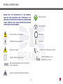
Instructions Manual
NEURODYN II
Manufactured by
Ibramed - Indústria Brasileira de Equipamentos Médicos EIRELI
Made in Brazil
nd
2 edition (LASTREV_08/2014)
TABLE OF CONTENTS
Caution: Federal Law restricts this device to sale by or on the order of a practitioner licensed by the law of the State
in which he/she practices to use or order the use of this device.
OPERATING INSTRUCTIONS.....................................30
SYMBOL DEFINITIONS..................................................3
ELECTRODE GUIDELINE...........................................36
CARTON..............................................................4
USING THE MENU/PROG BUTTON..............................40
ABREVIATIONS GLOSSARY.............................................4
CLINICAL RESOURCES LIBRARY - CLINICAL PROTOCOLS..42
FOREWORD.................................................................6
REFERENCES..........................................................45
PRODUCT DESCRIPTION................................................6
ACCESSORIES ACCOMPANYING NEURODYN II............46
SAFETY PRECAUTIONS..................................................7
TROUBLESHOOTING................................................47
PRECAUTIONARY DEFINITIONS..............................7
ELECTROTHERAPY INDICATIONS....................................9
MAINTENANCE, WARRANTY AND TECHNICAL SUPPORT...48
CONTRAINDICATIONS, WARNINGS AND PRECAUTIONS....10
CEFAI – IBRAMED Center for Education and
PREACAUTIONS AND ADVERSE REACTIONS....................11
Advanced Training.............................................50
GENERAL CARE WITH THE EQUIPMENT..........................12
INSTALLATION, CARE AND CLEANING....................12
ELETROMAGNECTIC COMPATIBILITY..............................14
NOMENCLATURE.........................................................20
CONTROLS, INDICATORS AND CONNECTIONS........20
SYMBOL DEFINITIONS........................................21
SPECIFICATIONS........................................................22
SYSTEM SPECIFICATIONS....................................22
WAVEFORM SPECIFICATIONS...............................23
REPLACEMENT ACCESSORIES..........................47
ACCESSORIES USED...................................................27
USING THE MENU/PROG BUTTON.................................29
2
SYMBOL DEFINITIONS
BELOW ARE THE DEFINITIONS OF THE SYMBOLS
USED ON THE EQUIPMENT AND THROUGHOUT THE
INSTRUCTIONS FOUND IN THIS MANUAL. UNDERSTAND
THESE SYMBOLS AND THEIR DEFINITIONS BEFORE
OPERATING THIS EQUIPMENT.
Start treatment.
Stop treatment.
Caution! Refer to user manual.
Off switch.
TYPE BF Electrical equipment.
On switch.
Dangerous voltage.
Voltage in AC (Alternating Current).
Electrical Network in AC
(Alternating Current).
CLASS II Electrical equipment.
Not protected against the harmful effects of
water penetration.
Sensitivity against electrostatic discharge.
3
SYMBOL DEFINITIONS
ABREVIATIONS GLOSSARY
CARTON
Fragile.
This side up.
Limits of temperature for storage and
packaging in °C (Celsius Degrees).
Keep away from the rain.
Stacking up.
Do not use
damaged.
if
the
packaging
Hz
Hertz (pulses per second)
mA
Milliampere
VA
Volt Ampere
TENS
Transcutaneous Electrical Nerve Stimulation
FES
Functional Electrical Stimulation
Cont
Continuous
Sync
Synchronous
Rec
Reciprocal
VIF
Variation/Phase Duration Frequency
Rise
Time of Increase Gradient
On
Time of Muscular Contraction
Decay
Time of Decrease Gradient
Off
Time of Muscular Relaxation
Manual stm
Manual Stimulation
is
Refer to operating instructions for
correct product use.
Manufacturer’s name and address.
4
FIGURES GLOSSARY
Figure 1. Upper Access Panel........................................20
Figure 2. Rear Access Panel..........................................20
Figure 3. Front Access Panel.........................................20
Figure 4. Lower Access Panel........................................20
Figure 5. A, Pin cables with banana ends (2 mm) and B,
Self-adhesive conductive electrodes................................27
Figure 6. A, the connectors must be affixed to your connection
on the panel of the device; B, the connector screws must be
firmly affixed; and C, put the banana pins cable inside the
electrode connector and not forget that the electrodes must
be positioned in pairs on the patient in accordance with the
colors of each channel..................................................28
Figure 7. LCD displays the selected language..................29
Figure 8. A, LCD Messages; B, NEURODYN II Electro
Stimulator Default Screen..............................................30
Figure 9. Bipolar Electrode Placement Technique.............37
Figure 10. Monopolar Electrode Placement Technique.......37
Figure 11.Positioning of the electrodes on the gastrocnemius
muscle.......................................................................38
Figure 12. Positioning of the electrodes on the posterior tibial
muscle.......................................................................38
Figure 13. Electrode sizes and current density................39
Figure 14. LCD displays the selection of Programmed and
User protocols..............................................................41
5
FOREWORD
PRODUCT DESCRIPTION
This user manual allows the user to efficiently use the
NEURODYN II Electro Stimulator. It also gives suggestions
for treatment protocols so that you can use your equipment
to its full potential.
NEURODYN II transcutaneous neuromuscular stimulator
is a four-channels stimulator with independent controls
for current therapies used in: TENS (Transcutaneous
Electrical Nerve Stimulation), FES (Functional Electrical
Stimulation) and Russian Current (Burst Modulated
Medium Frequency).
Consult other resources for additional information regarding
the uses of electrotherapy before attempting any treatment
on a patient. Users must read, understand and follow the
information in this manual for each mode of treatment
available, as well as the indications, contraindications,
warnings and precautions.
The equipment is to be used only under the prescription
and supervision of a licensed practioner.
The specifications and instructions in this manual are in
effect at the time of its publication. These instructions may
be updated at any time at the manufacturer’s discretion.
Visit our website for updates.
6
SAFETY PRECAUTIONS
PRECAUTIONARY DEFINITIONS
The precautionary instructions found in this section and
throughout this manual are indicated by specific symbols.
Understand these symbols and their definitions before
operating this equipment prior to therapy session.
• Read, understand, and practice the precautionary and
operating instructions. Know the limitations and hazards
associated with the use of any electrical stimulation.
Observe the precautionary and operational labels placed
on the unit.
• DO NOT operate this unit in an environment where other
devices intentionally radiate electromagnetic energy in an
unshielded manner.
Text with a “CAUTION” indicator refers to potential safety
infractions that could cause minor to moderate injury or
damage to equipment.
• This unit should be operated, transported and stored at
temperatures between 41°F and 122°F (5°C and 50°C);
Avoid damp and dusty environments.
Text with a “WARNING” indicator refers to potential
safety infractions that could cause serious injury and
equipment damage.
• Check cables and associated connectors before each
Text with a “DANGER” indicator refers to potential safety
infractions that represent immediately life threatening
situations that would result in death or serious injury.
a risk of injury to the patient.
use.
• The NEURODYN II Electro Stimulator is not designed
to prevent the infiltration of water or other liquids. The
infiltration of water or other liquids could cause malfunction
of internal components of the system and therefore create
• Disconnect the power plug from the outlet when left
unused for long periods of time.
7
SAFETY PRECAUTIONS
• To protect against the risk of fire, only use replacement
fuses of the same types and ratings.
• Stimulation should not be applied over the anterior neck
or mouth.
• Be sure the unit is grounded by connecting it to a grounded
electrical outlet compliant with the applicable national and
local electrical codes.
• Severe spasm of the laryngeal and pharyngeal muscles
may occur and the contractions may be strong enough to
close the airway or cause breathing difficulties.
• Powered muscle stimulators should be used only with
the lead wires and electrodes recommended for use by the
manufacturer.
• Stimulation should not be applied transthoracically to
avoid the introduction of electrical current into the heart
which may cause cardiac arrhythmia.
• Prior to patient treatment become familiar with the
operating procedures for each mode of treatment available,
as well as the indications, contraindications, warnings
and precautions. Consult other resources for additional
information regarding the applications of Electrotherapy.
• Stimulation should not be applied over swollen, infected,
and inflamed areas or skin eruptions such as phlebitis,
thrombophlebitis, varicose veins, etc.
• To prevent electrical shock, disconnect the unit from the
power source before performing any maintenance task.
• Output current density depends on the electrode size.
Improper application may result in patient injury. For any
question related to the correct electrode size, consult a
licensed practitioner prior to therapy session.
• Stimulation should not be applied on or near cancerous
lesions.
• Keep electrodes separated during treatment. Electrodes in
contact with each other could result in improper stimulation
or skin burns.
8
ELECTROTHERAPY INDICATIONS
SAFETY PRECAUTIONS
INDICATIONS FOR USE
Indications for Russian waveform:
• Patients with an implanted neurostimulation device must
not be treated with or be in close range of any shortwave
diathermy, microwave diathermy, therapeutic ultrasound
diathermy or laser diathermy anywhere on their
body. Energy from diathermy (shortwave, microwave,
ultrasound and laser) can be transferred through the
implanted neurostimulation system, can cause tissue
damage, and can result in severe injury or death. Injury,
damage or death can occur during diathermy therapy
even if the implanted neurostimulation system is powered
‘off’.
• Temporary relaxation of muscle spasms
• Prevention or retardation of disuse atrophy in post-injury
type conditions.
• Increase local blood circulation.
• Muscle re-education.
• Maintaining or increasing range of motion.
• Equipment not suitable for use in the presence of a
flammable anesthetic mixture with air, oxygen or nitrous
oxide.
Indications for TENS waveform:
Indications for FES waveform:
• Stimulation of the leg and ankle muscles of partially
paralyzed patients to provide flexion of the foot, thus
improving the patient’s gait.
• Symptomatic relief of chronic (long term) intractable
pain.
• Symptomatic relief of post-traumatic acute pain and
post-surgical acute pain.
Powered muscle stimulators should only be used under
medical supervision for adjunctive therapy for the treatment
of medical diseases and conditions.
9
CONTRAINDICATIONS, WARNINGS AND PRECAUTIONS
CONTRAINDICATIONS
• Do not apply stimulation when the patient is in the bath
or shower.
• Do not apply stimulation while the patient is sleeping;
• Do not apply stimulation while the patient is driving,
operating machinery, or during any activity in which
electrical stimulation can put the patient at risk of injury.
• Consult with the patient’s physician before using this
device, because the device may cause lethal rhythm
disturbances to the heart insusceptible individuals
• Apply stimulation only to normal, intact, clean and
healthy skin.
• Do not use this device on patients who have a cardiac
pacemaker, implanted defibrillator, or other implanted
metallic or electronic device because this may cause
electric shock, burns, electrical interference, or death.
• Do not user this device on patients whose pain syndromes
are undiagnosed.
WARNINGS
• Do not apply stimulation over the patient’s neck because
this could cause severe muscle spasms resulting in closure
of the airway, difficulty in breathing, or adverse effects on
heart rhythm or blood pressure.
• Do not apply stimulation across the patient’s chest,
because the introduction of electrical current into the chest
PRECAUTIONS
may cause rhythm disturbances to the patient’s heart,
which could be lethal.
• Do not apply stimulation over open wounds or rashes,
or over swollen, red, infected, or inflamed areas or skin
eruptions (e.g., phlebitis, thrombophlebitis, varicose
veins).
• Do not apply stimulation over, or in proximity to, cancerous
lesions.
• Do not apply stimulation in the presence of electronic
monitoring equipment (e.g., cardiac monitors, ECG
alarms), which may not operate properly when the electrical
stimulation device is in use.
• TENS is not effective for pain of central origin, including
headache;
• TENS is not a substitute for pain medications and other
pain management therapies;
• TENS devices have no curative value;
• TENS is a symptomatic treatment and, as such,
suppresses the sensation of pain that would otherwise
serve as a protective mechanism;
• Effectiveness is highly dependent upon patient selection
by a practitioner qualified in the management of pain
patients.;
10
PREACAUTIONS AND ADVERSE REACTIONS
PRECAUTIONS
• Use this device only with the leads, electrodes,
and accessories recommended by the manufacturer.
• Use this device only under the continued supervision of a
licensed practitioner.
• The long-term effects of electrical stimulation are unknown.
• Since the effects of stimulation of the brain are unknown,
stimulation should not be applied across the head, and
electrodes should not be placed on opposite sides of the
head.
• The safety of electrical stimulation during pregnancy has
not been established.
• Some patients may experience skin irritation or hypersensitivity due to the electrical stimulation or electrical
conductive medium (gel).
• Patients with suspected or diagnosed heart disease should
follow precautions recommended by their physicians;.
• Patients with suspected or diagnosed epilepsy should follow precautions recommended by their physicians.
• Use caution when the patient has a tendency to bleed
internally, such as following an injury or fracture.
• Use caution following recent surgical procedures when
stimulation may disrupt the patient’s healing process.
• Use caution if stimulation is applied over the menstruating
or pregnant uterus.
• Use caution if stimulation is applied over areas of skin
that lack normal sensation.
• Keep this device out of the reach of children.
ADVERSE REACTIONS
• Patients may experience skin irritation and burns
beneath the stimulation electrodes applied to the skin.
• Patients may experience headache and other painful
sensations during or following the application of electrical
stimulation near the eyes and to the head and face.
• Patients should stop using the device and should consult
with their physicians if they experience adverse reactions
from the device.
11
GENERAL CARE WITH THE EQUIPMENT
SHIPPING DAMAGE
NEURODYN II Electro Stimulator Care Instructions
Your NEURODYN II Electro Stimulator is shipped
complete in one carton. Upon receipt, inspect carton and
unit for visible and hidden damage. In case of damage,
keep all shipping materials including carton and contact
the shipping agent responsible for the delivery of the unit.
All claims relating to damage during transport should
be filed directly with them. The manufacturer will not
be liable for any damage during shipping, nor allow for
adjustments unless proper formal claim has been filed
by the receiver against the carrier. The carton in which
your NEURODYN II Electro Stimulator was received is
specially designed to protect the unit during shipping.
Please keep all shipping materials in case you need to
return your unit for servicing.
• Avoid areas subject to vibrations.
• Install the equipment on a firm and level surface, in open
air.
• Do not block ventilation.
• Avoid humid, hot and dusty environments.
• Make sure the area around the network cable is free.
• Do not insert objects into device holes.
Cleaning the NEURODYN II Electro Stimulator
Disconnect the system from the power source, wipe with
a clean, lint free cloth moistened with water and mild
antibacterial soap. If a more sterile cleaning is needed,
use a cloth moistened with an antimicrobial cleaner. Do
not place the system in liquids.
INSTALLATION, CARE AND CLEANING
Installation Instructions
• Connect the line cord to the back of the NEURODYN II
Electro Stimulator.
• Plug the line cord into a grounded wall outlet (100/240V
- 50/60 Hz).
• Plug the electrode cables into the electrode cable
connections.
• Switch on your equipment.
CORRECT EQUIPMENT INSTALLATION
PREVENTS SECURITY RISKS
12
GENERAL CARE WITH THE EQUIPMENT
Electromagnetic Compatibility Guidance
Medical Electrical Devices require special attention
regarding Electromagnetic Compatibility (EMC) and
must be installed and put into service according
to the EMC information provided in the following
tables.
The use of accessories, other than those listed, except
when supplied or sold by Ibramed Indústria Brasileira
de Equipamentos Médicos Ltda. as replacement parts
for internal or external components, may result in
increased emission or decreased immunity of the
NEURODYN II Electro Stimulator.
Portable and Mobile Radio Frequency (RF)
communications equipment can affect Medical
Electrical Devices.
13
ELETROMAGNECTIC COMPATIBILITY
Guidance and Manufacturer’s Declaration - Electromagnetic Emissions
The NEURODYN II is intended for use in the electromagnetic environment specified below. The customer or the
user of the NEURODYN II should ensure that it is used in such an environment.
Emission Test
Compliance
RF Emissions
CISPR 11
Group 1
RF Emissions
CISPR 11
Class A
Harmonic
Emissions
IEC 61000-3-2
Class A
Voltage fluctuations/
flicker emissions
IEC 61000-3-3
Class A
Electromagnetic environment - guidance
The NEURODYN II must emit electromagnetic energy
in order to perform it’s intend function. Nearby electronic
equipment may be affected.
The NEURODYN II is suitable for use in all establishments
other than domestic those directly connected to the public
low-voltage power supply network that supplies buildings
used for domestic purposes.
14
ELETROMAGNECTIC COMPATIBILITY
Guidance and Manufacturer’s Declaration - Electromagnetic Immunity
The NEURODYN II is intended for use in the electromagnetic environment specified below. The customer or the
user of the NEURODYN II should assure that it is used in such an environment.
IEC 60601
Test Level
Immunity Test
Electrostatic
discharge (ESD)
IEC 61000-4-2
Electrical fast
Transitories/burst
IEC 61000-4-4
Surge
IEC 61000-4-5
+
+
-
6 kV by contact
8 kV by air
+2
-
Compliance Level
+
+
-
6 kV by contact
8 kV by air
kV for power
supply lines
+ 1 kV for input/
output lines
+2
-
+1
-
+1
-
kV diferencial
mode
+ 2 kV common
mode
kV for power
supply lines
+ 1 kV for input/
output lines
kV diferencial
mode
+ 2 kV common
mode
15
Electromagnetic Environment - Guidance
Floors should be wood, concrete or ceramic tile.
If floors are covered with synthetic material, the
relative humidity should be at least 30%.
Mains power quality should be that of a typical
commercial or hospital environment.
Mains power quality should be that of a typical
commercial or hospital environment.
ELETROMAGNECTIC COMPATIBILITY
Guidance and Manufacturer’s Declaration - Electromagnetic Immunity
The NEURODYN II is intended for use in the electromagnetic environment specified below. The customer or the
user of the NEURODYN II should assure that it is used in such an environment.
Immunity Test
Voltage dips,
short interruptions
and voltage
variations in
power input lines
IEC 61000-4-11
Power frequency
(50/60 Hz)
magnetic field
IEC 60601
Test Level
Compliance Level
< 5% UT
(> 95% voltage drops
in UT ) 0.5 by cycle
< 5% UT
(> 95% voltage drops
in UT )by 0.5 ciclo
40% UT voltage drops
in
(60% UT ) by 5 cycles
40% UT
(60% de voltage drops
in UT )by 5 cycles
70% UT
(30% voltage drops in
UT ) by 25 cycles
70% UT
(30% voltage drops in
UT ) by 25 cycles
< 5% UT
(> 95% voltage drops
in UT ) by 5 seconds
< 5% UT
(> 95% voltage drops
in UT ) by 5 seconds
3 A/m
Electromagnetic Environment - Guidance
Mains power quality should be that of a typical
commercial or hospital environment. If the
user of the NEURODYN II requires continued
operation during power mains interruptions, it
is needed that the NEURODYN II be powered
from an uninterruptible power supply or battery.
Power frequency magnetic fields should be at
levels characteristic of a typical location in a
typical commercial or hospital environment.
3 A/m
IEC 61000-4-8
NOTE: UT is the A.C. mains voltage prior to applications of the test level.
16
ELETROMAGNECTIC COMPATIBILITY
Guidance and Manufacturer’s Declaration - Electromagnetic Immunity
The NEURODYN II is intended for use in the electromagnetic environment specified below. The customer or the
user of the NEURODYN II should assure that it is used in such an environment.
Immunity Test
IEC 60601
Test Level
Compliance
Level
Electromagnetic Environment - Guidance
Portable and mobile RF communication equipment should
not be used no closer to any part of NEURODYN II, including
cable than be separation distance calculated from the
equation applicable to the frequency of the transmitter.
Recommended separation distance
Conducted RF
IEC 61000-4-6
3 Vrms
150 kHz to 80 MHz
3V
Radiated RF
IEC 61000-4-3
3 V/m
80 MHz to 2.5 GHz
3 V/m
d = 1.2
d = 1.2
80 MHz to 800 MHz
d = 2.3
800 MHz to 2.5 GHz
Where p is the maximum output power rating of the
transmitter in watts (W) according to the transmitter
manufacturer and d is the recommended separation
distance in meters (m).
Field strengths from fixed RF transmitters, as determined
by an electromagnetic site survey,a should be less than the
compliance level in each frequency range.b
17
ELETROMAGNECTIC COMPATIBILITY
Guidance and Manufacturer’s Declaration - Electromagnetic Immunity
The NEURODYN II is intended for use in the electromagnetic environment specified below. The customer or the
user of the NEURODYN II should assure that it is used in such an environment.
Immunity Test
IEC 60601
Test Level
Compliance
Level
Conducted RF
IEC 61000-4-6
3 Vrms
150 kHz to 80 MHz
3V
Radiated RF
IEC 61000-4-3
3 V/m
80 MHz to 2.5 GHz
3 V/m
Electromagnetic Environment - Guidance
Interference may occur in the vicinity of equipment marked
with the following symbol:
NOTE 1: At 80 MHz and 800 MHz the higher frequency range applies.
NOTE 2: These guidelines may not apply in all situations. Electromagnetic propagation is affected by absorption and
reflection from structures, objects and people.
Field strengths set by fixed transmitters, such as radio base stations, telephone (cellular/cordless) telephones and land
mobile radios, amateur radio, AM / FM radio broadcast and TV broadcast cannot be predicted theoretically with accuracy.
To assess the electromagnetic environment due to fixed RF transmitters, an electromagnetic site survey should be
considered. If the measured field strength at the location in which the NEURODYN II is used exceeds the applicable RF
compliance level above, the NEURODYN II should be observed to verify normal operation. If abnormal performance is
observed, additional measures may be necessary, such as reorientation or relocating the NEURODYN II.
a
b
Over the frequency range 150 kHz to 80 MHz, field strengths should be less than 3 V / m.
18
ELETROMAGNECTIC COMPATIBILITY
Recommended separation distances between the mobile RF communication equipment and NEURODYN II
The NEURODYN II is intended for use in an electromagnetic environment in which radiated RF disturbances are
controlled. The customer or the user of the NEURODYN II can help prevent electromagnetic interference by
maintaining a minimum distance between portable and mobile RF communications equipment (transmitters) and the
NEURODYN II as recommended below, according to the maximum output power of the communications equipment.
Rated maximum power
output of transmitter
w
Separation distance according to frequency of transmitter
m
150 kHz to 80 MHz
80 MHz to 800 MHz
800 MHz to 2.5 GHz
d = 1.2
d = 1.2
d = 2.3
0.01
0.12
0.12
0.23
0.1
0.38
0.38
0.73
1
1.2
1.2
2.3
10
3.8
3.8
7.3
100
12
12
23
For transmitters rated at a maximum output power not listed above, the recommended separation distance d in meters
(m) can be estimated using the equation applicable to the frequency of the transmitter, where P is the maximum output
power rating of the transmitter in watts (W) according to the transmitter manufacturer.
NOTE 1: 80 MHz to 800 MHz, the separation distance for the higher frequency range applies.
NOTE 2 These guidelines may not apply in all situations. Electromagnetic propagation is affected by absorption and
reflection from structures, objects and people.
19
NOMENCLATURE
CONTROLS, INDICATORS AND CONNECTIONS
15
16
13
1
11
12
14
Figure 2. Rear Access Panel.
Figure 4. Lower Access Panel.
Figure 1. Upper Access Panel.
1- Power ON/OFF Switch.
2- Power On Indicator LED.
3- BACK/NEXT Buttons.
4- SET + /SET - Buttons.
5- LED Display.
6- START/STOP.
Figure 3. Front Access Panel.
7- PROG/MENU Button. PROG: Select
Protocols, Clinical Resources Library and
MENU: Select Language.
8- Channel indicator LEDs.
9- UP/DOWN Intensity Buttons; Channel 1, 2, 3
and 4.
10- Channel Lead Wire Connectors.
20
11- Fuse.
12- Line Cord Connection.
13- General Characteristics Label.
14- Current output label characteristics.
15- Caution: Federal Law (USA).
16- Serial Number.
NOMENCLATURE
SYMBOL DEFINITIONS
Read and Understand these symbols and their definitions before operating this equipment.
Before using and operating the NEURODYN II, please read and learn the symbols on the LCD device.
Switch used to start or stop treatment.
Always press the center of the switch.
Channel Lead Wire Connectors. Channel 1, 2, 3 and 4.
Switch with double function:
PROG Selection of pre programmed
protocols and private protocols;
MENU – Selection of language (Portuguese,
English or Spanish).
SELECT: switch for the selection of parameters.
Up or Down Intensity: Channel 1, 2, 3 and 4. Observe
the colors related to channels.
SET: switch for selection of values of the parameters.
21
SPECIFICATIONS
SYSTEM SPECIFICATIONS
Dimensions
Width:
6.89 in (17.5 cm)
Depth:
10.83 in (27.5 cm)
Height:
4.53 in (11.5 cm)
Standard Weight
(without accessories): 1.3 kg
Power
Input:
100 - 240V~
Input Power:
85 VA
Fuses:
5A
Electrical Class:
CLASS II
Electrotherapy:
TYPE BF
250V~
50/60 Hz
(20AG)
Regulatory Compliance
IEC
IEC
IEC
IEC
60601-1
60601-1-2
60601-1-4
60601-2-10
Temperature Range During Transport and Storage:
Between 59 and 104°F.
Environment operating temperature range:
5 - 45 °C / 41- 113 °F.
22
SPECIFICATIONS
WAVEFORM SPECIFICATIONS
Between the minimum and maximum frequency the polarity
changes by 1 second to 2 milliseconds for TENS/FES and
The frequency for Russian is fixed; therefore, the rate of
inversion of polarity is also fixed. The frequency is 2500 Hz
which represent a period of 0.4 milliseconds, so this inversion
0.2 milliseconds for Russian.
of polarity occurs at every 0.2 milliseconds.
Minimum
Russian Fixed in 2500 Hz/ period =0.4 milliseconds /polarity
Period = 1/250 Period =4 milliseconds.
Inversion Polarity= Period/2
inversion = 0.2 milliseconds.
Maximum
onds.
Russian Fixed in 2500 Hz/ period =0.4 milliseconds /polarity
The polarity changes through the type of current chosen
(i.e. Russian, TENS or FES) and frequency chosen. There
is no direct option to control the polarity. The rate charge
depends on the frequency set by the User. There are no
For example: (Frequency =250Hz):
Period = 1/Frequency
Inversion Polarity = 4/2, Inversion Polarity =2millisec-
inversion = 0.2 milliseconds.
For TENS and FES currents, the frequency can be adjusted
specific modes the user can choose to change the polarity.
by the user; therefore, the polarity varies according to the
frequency. The frequency may be adjusted between 0.5 to
250 Hz which represents a period from 2s to 4 milliseconds,
so the inversion of polarity may vary between 1 second to 2
milliseconds.
Minimum
TENS and FES Frequency minimum = 0.5 Hz /period = 2
seconds / polarity inversion =1 second.
Maximum
TENS and FES Frequency maximum = 250 Hz /period = 4
milliseconds / polarity inversion =2 milliseconds.
23
SPECIFICATIONS
WAVEFORM SPECIFICATIONS
TENS
Symmetrical Biphasic
TENS and FES Current
Russian Current
Output Mode
Electrodes
Output Intensity (CC*)
Frequency
Phase Duration
Burst Frequency Modulation of Burst Frequency
0-120 mA peak to peak
0,5-250 Hz
Adjustable 50-500 μs
2 Hz
250 Hz
Frequency/Phase Duration Variation: VIF Frequency
VIF Phase Duration
Note: The TENS, FES and Russian are depolarized currents.
The Russian current has a fixed frequency of 2.5 kHz (rate
of reversal) and TENS and FES current frequency can be
adjusted from 0.5 - 250 Hz (reversal rate).
The user chooses the frequency rate (reversal) for the
TENS and FES (0.5-250 Hz) modes, according to the
desired treatment.
The TENS, FES and Russian presents automatic polarity
reversal according to the frequency.
VIF
2-247 Hz
50-500 μs
Current Mode
Conventional (Normal) TENS (R 0.5-250 Hz; T 50-500 μs)
Burst Modulation
TENS Burst (R 250 Hz; T 50-500 μs)
Treatment Time
Set Intensity
CC*= Constant Current
24
1-60 min
Individual channel intensity
setting 1, 2, 3 or 4.
SPECIFICATIONS
WAVEFORM SPECIFICATIONS
FES
Output Mode: Electrodes
Output Intensity (CC*): 0 - 120 mA peak to peak
Current Mode
Synchronous: FES Sync (1, 2, 3 &4 channel)
Reciprocal: FES Rec (1&3, 2 & 4 channel)
Frequency/Phase Duration Variation: VIF
(R 2 - 247 Hz; T 50 - 500 μs)
Frequency: 0.5 - 250 Hz
Phase Duration (Pulse): 50 - 500 μs
VIF Frequency: 2 - 247 Hz
VIF Phase duration: 50 - 500 μs
Ramp
Rise (Time of Increase Gradient): 1 - 9 s
On (Time of Muscular Contraction):1 - 60 s
Decay (Time of Decrease Gradient): 1 - 9 s
Off (Time of Muscular Relaxation): 1 - 60 s
Treatment Time: 1 - 60 min
Set Intensity: Individual Channel Intensity Setting
Functional Electrical Stimulation
CC*= Constant Current
Available on Channels: 1, 2, 3 or 4
25
SPECIFICATIONS
WAVEFORM SPECIFICATIONS
Russian Current
Output Mode: Electrodes
Output Intensity (CC*): 0 - 120 mA peak to peak
Current Mode
Continuous: Russian Cont (1, 2, 3 & 4 channel)
Synchronous: Russian Sync (1, 2, 3 & 4 channel)
Reciprocal: Russian Rec (1 & 3, 2 & 4 channel)
Burst Duration (Duty cycle): 10%, 20%, 30%, 40% or
50%
Burst Frequency: 10 - 100 Hz (steps of 10 Hz)
Ramp
CC*= Constant Current
Rise (Time of Increase Gradient): 1 - 9 s
On (Time of Muscular Contraction): 1 - 60 s
Decay (Time of Decrease Gradient): 1 - 9 s
Off (Time of Muscular Relaxation): 1 - 60 s
Treatment Time: 1 - 60 min
Set Intensity: Individual Channel Intensity Setting
Available on Channels: 1, 2, 3 or 4
26
ACCESSORIES USED
TENS, FES or RUSSIAN: pin connector cables with banana ends (2 mm) and conductive self-adhesive electrodes
(Figure 5).
A.
B.
Figure 5. A, Pin cables with banana ends (2 mm) and B, Self-adhesive conductive electrodes.
27
ACCESSORIES USED
A
B
C
Figure 6. A, the connectors must be fixed to your connection on the panel of the device; B, the connector screws must be firmly
fixed; and C, put the banana pin cable inside the electrode connector and remember that the electrodes must be positioned in
pairs on the patient in accordance with the colors of each channel.
NOTE: To remove the banana pins from the self-adhesive electrodes, pull them by their protective cover. Never pull the cord.
The TENS, FES and RUSSIAN currents are depolarized currents and they do not require specific positioning for the cathode and
anode electrodes, unlike polarized currents. The electrodes must be positioned in pairs on the patient in accordance with the
colors of each channel (orange, black, blue and green).
Continuous Current (Polarized) - Charges move always in the same direction it is that in which the continuous
flow follows only one direction (Unidirectional).
Alternating Current (Depolarized) - There is the inversion of polarity ate regular time intervals, it is that in which the current
flows first in one direction then another (Bidirectional continuous flow).
28
USING THE MENU/PROG BUTTON
USING THE MENU BUTTON
SELECT THE LANGUAGE
The MENU/PROG button is used to select the language.
Press MENU/PROG until you hear three “beeps.” Select the
desired language: ‘Português’, ‘Español or ‘English’ (figure
7).
Figure 7. LCD displays the selected language.
29
OPERATING INSTRUCTIONS
PREPARE DEVICE
Edit Waveform Parameter
The SELECT buttons allow you to select the parameters
required for the treatment. Press the cursor keys to move
to the next parameter or rewind the cursor back to the
previous setting.
The SET buttons allow you to select the values of each
parameter required for the treatment.
Turn the power switch on. LCD displays the message device
presentation for a few seconds, followed by the software
model of the device default screen programming (Figure 8).
A
B
Time Parameters
Set the session time using the SELECT and SET keys. Using
the SELECT key scroll through the parameters until the
timer parameter is located. Press SET key to select and to
choose the timer desired. At the end of the scheduled time,
you will hear a beep indicating that the emission current has
been interrupted. Press the STOP button, the sound signal
turns off and the equipment goes back to the programming
status.
Start Treatment
Press the START button to begin therapy
session.
Stop Treatment
Press the STOP button to end therapy
session.
Figure 8. A, LCD Messages; B, NEURODYN II Electro
Stimulator Default Screen.
Note that entering the default screen will cause the word
TENS to flash. The ‘selection cursor parameters’ will
appear in the Current word and now the device can be
programmed.
30
OPERATING INSTRUCTIONS
The Waveform Intensity may be increased or decreased at
any time during the session. Press the INTENSITY button
UP or DOWN.
2. Using the SELECT key scroll through the parameters until
the desired parameter is located. Press SET key to select and
to choose the status of the parameter desired. With SELECT
key press the arrow down or up to move to the next input.
Continue in this manner until all parameters are chosen.
PROGRAMMING EQUIPMENT
A
Waveform Intensity
Example 1 (TENS): Suppose the clinical practice or
literature to suggest certain pathology TENS current type
with automatic variation of intensity and frequency (VIF ON)
and the treatment time of 40 min.
1. Connect the equipment to start programming the pattern
described above. Using the SELECT key scroll through the
parameters until appear “Current”. After this, press SET key
to select and to choose the status TENS. Note the blinking
cursor in the TENS field as shown in the figure below.
B
31
OPERATING INSTRUCTIONS
PROGRAMMING EQUIPMENT
A
Example 2 (FES): Suppose the clinical practice or literature
to suggest certain pathology FES current type, synchronous,
50 Hz, 200 μs, ramp: Rise 2 s, On 10 s, Decay 2 s, Off 10 s
Manual stm and the treatment time of 15 min.
1. Connect the equipment to start programming the pattern
described above. Using the SELECT key scroll through the
parameters until appear “Current”. After this, press SET key
to select and to choose the status FES. Note the blinking
cursor in the FES field as shown in the figure below.
B
C
2. Using the SELECT key scroll through the parameters until
the desired parameter is located. Press SET key to select and
to choose the status of the parameter desired. With SELECT
key press the arrow down or up to move to the next input.
Continue in this manner until all parameters are chosen.
32
OPERATING INSTRUCTIONS
D
G
E
H
F
33
OPERATING INSTRUCTIONS
2. Using the SELECT key scroll through the parameters until
the desired parameter is located. Press SET key to select and
to choose the status of the parameter desired. With SELECT
key press the arrow down or up to move to the next input.
Continue in this manner until all parameters are chosen.
PROGRAMMING EQUIPMENT
Example 3 (Russian): Suppose the clinical practice or
literature to suggest certain pathology Russian current type,
synchronous, 50 Hz, 50%, ramp: Rise 2 s, On 10 s, Decay 2
s, Off 10 s and the treatment time of 15 min.
A
1. Connect the equipment to start programming the pattern
described above. Using the SELECT key scroll through the
parameters until appear ‘Current”. After this, press SET key
to select and to choose the status Russian. Note the blinking
cursor in the Russian field as shown in the figure below.
B
34
OPERATING INSTRUCTIONS
C
F
D
G
E
H
35
ELECTRODE GUIDELINE
OPERATING INSTRUCTIONS
PATIENT PREPARATION
3. Once all parameter are chosen, press the START button
to begin treatment.
Prepare the patient for therapy as described and read about
the use of electrodes.
• Electrode Placement can be achieved using the Bipolar or
Monopolar Techniques. Proper positioning and contact will
insure treatment comfort and efficiency.
• Examine the skin for any wounds and clean the treatment
area by rubbing the skin with medical grade alcohol.
• Remove the self-adhesive electrodes from the protective
backing and apply to the treatment area as prescribed.
• Ensure the entire electrode surface is in contact with
patient skin by pressing into place.
• Check the electrode contact regularly during treatment.
• Examine the skin again after the treatment.
4. Press the UP or DOWN channel in use to select the
amount of current needed to treat.
Note: The intensity adjustment may be made before or
after pressing the START button. In order to make the
intensity adjustment before pressing START, the operator
must adjust the quantity of current necessary for a particular
patient and after pressing the START button, a gradual
increase in intensity will occur until the quantity of current
previously adjusted is reached. In case during the gradual
increase in intensity the operator notices that the intensity
of current is above the tolerable limit for the patient, press
the DOWN button so that there is decrease in the quantity
of current until the ideal quantity of current for the patient
is reached.
ELECTRODE - BIOCOMPATIBILITY (ISO 10993):
Ibramed declares that the electrodes supplied with the
equipment do not cause allergic reactions. These electrodes
must only be put in contact with the integral surface of the
skin, respecting the time limit of the duration of this contact
of up to 24 hours.
5. At the end of the programmed time, the emission current
is interrupted and an audible alarm will signal the treatment
end.
6. Press the STOP button to stop the alarm. The equipment
can now be switched off, repeat the same programming
task, or undertake a new programming task.
36
ELECTRODE GUIDELINE
ELECTRODE POSITIONING
Bipolar Electrode Placement Technique
Monopolar Electrode Placement Technique
The technique of positioning the bipolar electrodes is used to
provide stimulation of the large groups of muscles, such as
the quadriceps or ischiotibial muscles. Electrodes of similar
size are placed over each extremity of the muscle or muscle
group. The Neurodyn II electrostimulator offers wave formats for bipolar stimulation: Transcutaneous Nervous Electrical Stimulation (TENS), Functional Electrical Stimulation
(FES) and Russian Current (Russian).
The Monopolar Electrode Placement Technique has been
found to be especially useful for muscle stimulation of the
upper extremities and small muscle groups. The smaller
electrode is placed over the muscle motor point and the
lager electrode is placed over the painful area. The Neurodyn
II Electrostimulator offers wave forms for monopolar
stimulation: Functional Electrical Stimulation (FES) and
Russian Current (Russian).
Figure 9. Bipolar Electrode Placement Technique.
Figure 10. Monopolar Electrode Placement Technique
37
ELECTRODE GUIDELINE
ELECTRODE POSITIONING
Positioning of the Electrodes for Foot Drop
Positioning of the Electrodes for Foot Drop
Positioning of the electrodes on the gastrocnemius muscle
- motor point (on the muscle belly).
Positioning of the electrodes on the posterior tibial muscle
- motor point (on the muscle belly).
Figure 11. Positioning of the electrodes on the
gastrocnemius muscle.
Figure 12. Positioning of the electrodes on the
posterior tibial muscle.
38
ELECTRODE GUIDELINE
Placement of the electrodes near the chest may
increase the risk of cardiac fibrillation.
Electrode Sizes and Current Density
The size of the electrodes and the energy density used during therapy must comply with IEC 60601-2-10, i.e., the current
density per area of electrode should not exceed 2 mA/cm2. The smallest electrode size that may be used with this device is
25 cm².
We recommend the use of electrodes provided by Axelgaard Manufacturing Co., Ltd. Fallbrook, CA 92028, USA. FAX +1 (760)
723 2356. www.axelgaard.com.
Figure 13. Electrode sizes and current density.
39
USING THE MENU/PROG BUTTON
USING THE PROG BUTTON
SELECT THE PRE-PROGRAMMED PROTOCOLS
Turn the equipment on as described above. Press briefly
the PROG button and press the SET button to select the
PROGRAMMED protocols. Next, the information of the
first treatment protocol in the equipment will appear on
the display. Use the SET button to select another protocol.
See the details in the tables below. If this is the chosen
protocol, press the PROG button once more. The display
will show the parameters for the selected protocol, including
or not including the intensity desired. Then, just press the
START button and, in case the intensity was not adjusted
previously, select the intensity of current desired.
Proceed the same way to select any of the protocols
available. Just follow the steps above.
40
USING THE MENU/PROG BUTTON
PROGRAMMING USER PROTOCOLS
PROGRAMMING THE MANUAL STIMULATION
In order to program the manual stimulation, it is necessary to
adjust the parameters which will be used in the Therapy with
the FES Sync (Synchronized FES) or FES Rec (Reciprocal
FES) modes, except the parameter OFF, because it is the
therapist who will trigger the stimulation manually. When
the Manual stm function (Manual Stimulation) is selected,
the stimulation is performed manually. For this function to
be active, (ON), the therapist must select the Manual stm
mode using the SELECT buttons and with the SET buttons
choose the Status ON. After that, press the START button
to start the therapy. In this function, the equipment will
execute the rise, on and decay ramps, and stop, that is,
remain in off (rest) for the time the therapist considers
To program new protocols, press the PROG key briefly and
press the SET button to select the USER protocols. With the
SET button, choose one of the 20 USER protocols available.
Adjust the parameters according to the therapeutic needs and
press START. The last parameters defined will be recorded in
the equipment memory. To access the protocols saved by the
user, just select the PROG button and use the SET buttons to
choose the number of the desired protocol.
necessary. To start the stimulation again, it is necessary
to press PROG button, which, once pressed, will make the
equipment execute the stimulation again following the rise,
on and decay ramps programmed for the type of current
FES Sync (Synchronized FES) or FES Rec (Reciprocal FES).
The manual stimulation mode will be active until the end of
the programmed treatment time. To cancel it the therapist
must press the STOP button.
Figure 14. LCD displays the selection of Programmed
and User protocols.
41
CLINICAL RESOURCES LIBRARY - CLINICAL PROTOCOLS
Prog: 1 - TENS
Prog: 2 -TENS
Post-traumatic Acute Pain
Description: Modulation
Post-traumatic acute pain
Parameters values
Post-surgical Acute Pain
Description: Modulation
post-surgical acute pain
of
Parameters values
of
Current
TENS
Current
TENS
Mode
Conv
Mode
Conv
Frequency
100 Hz
Frequency
150 Hz
Phase duration (Pulse)
200 μs
Phase duration (Pulse)
75 μs
Treatment time (Timer)
30 min
Intensity
1 to 120 mA*
Treatment time (Timer)
30 min
Positioning of electrodes
On the painful area
Intensity
1 to 120 mA*
Positioning of electrodes
On the painful area
*Manufacturer does not preset the intensity because it needs to be adjusted by the therapist in accordance to the patient’s
needs and treatment plan. It can be increased or decreased on the appropriate channel by pushing the up and down button.
42
CLINICAL RESOURCES LIBRARY - CLINICAL PROTOCOLS
Prog: 3 - TENS
Chronic Intractable Pain
Prog: 4 - RUSSIAN
Parameters values
Muscle re-education
Description: Modulation of
chronic intractable pain
Parameters values
Description: Muscle
re-education
Current
TENS
Current
Russian
Mode
Conv
Mode
Sync
Frequency
40 Hz
Burst duration (Duty cycle)
10%
Phase duration (Pulse)
150 μs
Burst Frequency (Burst freq)
50 Hz
Treatment time (Timer)
30 min
Rise
1s
Intensity
1 - 120 mA*
On
3s
Decay
1s
Off
3s
Treatment time (Timer)
15 min
Intensity
1 - 120 mA*
Positioning of electrodes
On the muscular
center or on the
motor muscular point
Positioning of electrodes
One electrode channel
on the dermatome
corresponding to the
pain and the second
on the nerve root
corresponding to the
dermatome in which
the pain is localized
*Manufacturer does not preset the intensity because it needs to be adjusted by the therapist in accordance to the patient’s
needs and treatment plan. It can be increased or decreased on the appropriate channel by pushing the up and down button.
43
CLINICAL RESOURCES LIBRARY - CLINICAL PROTOCOLS
Prog: 5 - RUSSIAN
Maintaining or Increasing
Range of Motion
Description: Maintaining or
increasing range of motion
Parameters values
Current
Mode
Russian
Sync
Burst duration (Duty cycle)
50%
Burst Frequency (Burst freq)
50 Hz
Rise
3s
On
8s
Decay
3s
Off
16 s
Treatment time (Timer)
25 min
Intensity
1 to 120 mA*
Positioning of electrodes
On
the
muscular
center or on the motor
muscular point
*Manufacturer does not preset the intensity because it needs to be adjusted by the therapist in accordance to the patient’s
needs and treatment plan. It can be increased or decreased on the appropriate channel by pushing the up and down button.
44
REFERENCES
Medicine and Rehabilitation. 2004; 85(3): 409-415.
DeSantana JM, Walsh DM, Vance C, Rakel BA, Sluka KA.
Effectiveness of transcutaneous electrical nerve stimulation
for treatment of hyperalgesia and pain. Curr Rheumatol
Rep. 2008; 10(6): 492-9.
Robertson VJ, Ward AR. Use of electrical stimulation to
strengthen the vastus medialis muscle following a lateral
patellar retinacular release. Journal of Orthopaedic and
Sports Physical Therapy. 2002; 32(9): 437-446.
Delitto A, Rose SJ, McKowen JM et al. Electrical stimulation
versus voluntary exercise in strengthening thigh musculature
after anterior cruciate ligament surgery. Phys. Ther. 1988;
68 (5): 660 – 663.
Selkowitz DM. High frequency electrical stimulation in muscle
strengthening. A review and discussion. Am. J. Sports Med.
1989; 17(1): 103 – 111.
Gersh, MR, Wolf, SL. Applications of Transcutaneous
Electrical Nerve Stimulation in the management of patients
with pain. Phys. Ther.1985; 65 (3): 314-336.
Shanahan C, Ward AR, Robertson VJ. A Comparison of
the analgesic efficacy of interferential therapy and TENS.
Physiotherapy. 2006; 92(4): 247-253.
Guirro R, Nunes CV, Davini R. Comparação dos efeitos de
dois protocolos de estimulação elétrica neuromuscular
sobre a força muscular isométrica do quadriceps. Rev.
fisioter.Univ.São Paulo. 2000; 7(1/2): 10-15.
Snyder-Mackler L, Garrett M, Roberts M. A comparison of
torque generating capabilities of three different electrical
stimulating currents. J Orthop Sports Phys Ther. 1989;
10(8): 297-301.
Laufer Y, Ries JD, Leininger PM, Alon G. Quadriceps
femoris muscle torques produced and fatigue generated
by neuromuscular electrical stimulation with three different
waveforms. Phys Ther. 2001; 81(7): 1307-1316.
McManus FJ, Ward AR, Robertson VJ. The analgesic effects
Snyder-Mackler L, Delitto A, Stralka SW, Bailey SL. Use of
electrical stimulation to enhance recovery of quadriceps
femoris muscle force production in patients following anterior
cruciate ligament reconstruction. Phys. Ther. 1994; 74(10):
901 – 907.
of interferential therapy on two experimental pain models:
cold and mechanically induced pain. Physiotherapy. 2006;
92 (2): 95-102.
ST Pierre D, Taylor AW, Lavoie M. et al. Effects of 2500-Hz
sinusoidal current on fibre area and strength of quadriceps
femoris. J Sports Med Phys Fitness. 1986; 26(1):60-66.
Ozcan J, Ward AR, Robertson VJ. A comparison of true and
premodulated interferential currents. Archives of Physical
45
ACCESSORIES ACCOMPANYING NEURODYN II
Ibramed NEURODYN II contains accessories designed to meet the requirements of electromagnetic comparability accessories
(accessories code 03018108, 02049011 and 02049031).
PART NUMBER
QUANTITY
ITEM DESCRIPTION
03018108
01
Cable PP 2 X 0,75 with 1,50MT Black Plug 180º NEMA 2P
with Plug 180º FDA
02049011
01
Cable 09 Kit for NeuroII (Blue/Green 2 ways each)
02049031
01
Cable 38 Electrostimulation Kit (Black/Orange 2 ways)
03026031
02
Electrode - Valu Trode - Model VL4545 (four/electrode/
pkg)
03040008
01
Digital Operations Manual Neurodyn II FDA
03019012
01
Protection fuse 20AG 2A
03026009
01
Protection Fuse Chart
03026003
01
Bag sapphire line
46
ACCESSORIES ACCOMPANYING
NEURODYN II
TROUBLESHOOTING
PROBLEMS
REPLACEMENT ACCESSORIES
This list of replacement accessories are designed for use
with the NEURODYN II Electro Stimulator. When ordering,
provide the respective part numbers, description, and
quantity desired.
The use of accessories, cables and electrodes other than
those intended for this specific equipment may significantly
degrade the performance of the emissions and immunity.
DO NOT USE accessories, cables and electrodes from
NEURODYN II equipment on other equipment or medical
electro systems.
TROUBLESHOOTING
The equipment does
not turn on 1.
• Is the power cable properly
connected?
If not, connect it. Also check the
wall socket.
The equipment does
not turn on 2.
• Have you checked the safety fuse?
Check if there is a bad contact.
Check if the value is correct as
stated in the instructions.
The equipment is
turned on but does
not emit current to
patient 1.
•
Have
you
followed
the
recommendations for correct use
the equipment as mentioned in
the instructions?
Check and repeat the steps in
the controllers, indications and
operation section.
The equipment is
turned on but does
not emit current to
patient 2.
• Have you checked the electrodes
and the connecting cables to the
patient?
Check if the cable plug is adequately
inserted in the equipment.
Check if the electrodes are
adequately placed on the patient’s
body.
The equipment does
not turn on and/or
work properly.
• Check if the amount of gel is
enough.
• Check if the electrodes are worn
properly.
What may initially look like a problem is rarely a defect.
Before calling customer support, please check the items
described below:
47
SOLUTIONS
MAINTENANCE, WARRANTY AND TECHNICAL SUPPORT
MAINTENANCE
WARRANTY TERMS
For safe use of the equipment, it is recommended to have it
inspected and undergo preventive maintenance at IBRAMED
or an authorized technical center every 12 months. The
manufacturer IBRAMED only assumes liability for the
technical features and equipment safety provided the unit
is used according to the instructions for use contained in
the manual, when maintenance, repairs and modifications
are undertaken solely by the factory or authorized agents,
and in the event of a breakdown when the components
that can cause a security risk to the appliance are replaced
by original spare parts. If requested, IBRAMED will provide
technical documentation (circuit diagrams, lists of parts and
1) IBRAMED warrants that this product is free of
manufacturing defects for eighteen (18) continuous months,
provided the set terms presented in these instructions for
use are followed.
components etc) necessary for the repair of any equipment.
We assume no responsibility for repairs without prior explicit
written permission from IBRAMED.
3) Customer Service during the warranty period will be
provided exclusively at IBRAMED sale points by IBRAMED
itself or another agent designated by the manufacturer.
2) The warranty period takes effect from the date of
purchase and applies to the original purchaser only, even
in the event of a product being transferred to a third party.
The warranty covers the replacement of component parts
and labor required to repair defects whenever the presence
of such manufacturing defects can be determined.
WARRANTY
4) The warranty does not cover damage caused to the
product resulting from:
a) Failure to follow the specifications and
recommendations detailed in these instructions for use
during installation or use of the product.
b)
Accidents or acts of God, connections to
electrical system with inappropriate voltage and/or
subjected to excessive fluctuation or overcharge.
IBRAMED, Indústria Brasileira de Equipamentos Médicos.,
here identified to the consumer through the following
address and telephone number: Av. Dr. Carlos Burgos,
2800, Jd Itália, Amparo/SP, Brazil; Phone: +55 19 3817
9633 provides product-warranty for eighteen (18) months
insofar as the conditions set for warranty terms are followed
by the user as mentioned below.
48
MAINTENANCE, WARRANTY AND TECHNICAL SUPPORT
c)
Misuse, lack of reasonable care, product
alterations, modifications or repairs undertaken by
individuals or entities not authorized by IBRAMED.
d)
Removal or adulteration of the equipment serial
number.
e)
Damage during Transport.
TECHNICAL SUPPORT
If you have any doubts or problems related to the operation
of your equipment, please contact:
IBRAMED USA REPRESENTATIVE
QS Health
223 E Flager Street, Suite 402
Miami – FL 33131
Sales: 1.888.275.0025 x 2
Phone: 1.786.254.7723
Fax: 786.358.6072
Email: [email protected]
Website: www.ibramed.us
5)
The legal warranty does not cover: expenses incurred
during product installation or transport to the plant or sale
point, labor, materials, parts and adjustments necessary to
the readiness of the premises in view of the installation of
the device, such as but not limited to electric net, masonry,
hydraulic network, grounding system, as well as their
requirements.
6)
The warranty does not cover parts subjected to
natural wear, such as but not limited to control buttons,
control keys, handles and moving parts, radiofrequency
applicators, cooling applicator, cables, connectors, device
cabinets, pedal, infrared thermometer.
Do not alter this equipment. Any unauthorized
modification can affect the safety of this
equipment.
Never make unauthorized repairs.
7)
The selling points are neither authorized to alter
the conditions mentioned in this document nor take any
commitment on behalf of IBRAMED.
49
CEFAI – IBRAMED Center for Education and Advanced Training
IBRAMED Equipment goes beyond technology. It also provides knowledge! Science constitutes our differential value
and we effectively take advantage of its benefits in order to
ensure patient safety and thereby maximize results.
Special attention is also given to those interested in visiting
our structure. Whatever your professional development
needs, we’ll be right by your side to provide you with
unconditional support.
IBRAMED develops products with scientific support of the
most recent medical studies published in major scientific
journals in the areas of biological, health and exact.
We are happy to assist you!
Contact – [email protected]
www.conexaocefai.com.br
+55 19 3808. 2348
Access to the knowledge database is guaranteed by CEFAI
(IBRAMED Center for Education and Advanced Training)
whose goal is to provide technical and scientific support
as well as current literature on therapies and their appli-
Thanks,
cability while our treatment choices are always thoroughly
selected according to the best and latest clinical criteria.
CEFAI takes into account the personal and professional development of all its partners and customers.
IBRAMED – A matter of respect!
CEFAI invites both students and professionals in the fields
of Physical Rehabilitation, Esthetics, Physiotherapy, Dermatology and Esthetic Medicine to take part in free courses,
workshops, and the best Postgraduate Lato Sensu courses
in the areas of physical rehabilitation and esthetics.
50
Manufactured by IBRAMED
Indústria Brasileira de Equipamentos Médicos EIRELI
Av. Dr. Carlos Burgos, 2800 - Jd. Itália
13901-080 - Amparo - SP - Brazil
Phone: +55 19 3817 9633
www.ibramed.us
[email protected]