1
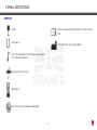
Instruction Manual
NEURODYN
Compact
Manufactured by IBRAMED
Indústria Brasileira de Equipamentos Médicos EIRELI
ANVISA nº 10360310012
th
6 edition (REV. 08/2012)
TABLE OF CONTENTS
SYMBOL DEFINITIONS................................................3
CARTON............................................................4
ACCESSORIES USED.................................................34
ABREVIATIONS GLOSSARY...........................................5
OPERATING INSTRUCTIONS.......................................35
LIST OF FIGURES.......................................................5
PREPARE DEVICE.............................................35
FOREWORD...............................................................6
PROGRAMMING EQUIPMENT...............................36
ELECTROTHERAPY PATIENT PREPARATION...........37
ESSENTIAL PERFORMANCE..................................6
WAVEFORM SPECIFICATIONS.............................31
PRODUCT DESCRIPTION..............................................6
ELECTRODE GUIDELINE.............................................37
SAFETY PRECAUTIONS................................................7
USING THE MS/PROG BUTTON...................................40
INDICATIONS, CONTRAINDICATIONS, PRECAUTIONS AND
SELECT THE LANGUAGE....................................40
ADVERSE REACTIONS...............................................10
USING THE PROG BUTTON.................................40
POPULATION AND CONDITIONS OF USE.......................14
PROGRAMMING USER PROTOCOLS.....................41
GENERAL CARE WITH THE EQUIPMENT........................15
CLINICAL RESOURCES LIBRARY - CLINICAL PROTOCOLS..42
SHIPPING DAMAGE...........................................15
REFERENCES...........................................................58
INSTALLATION, CARE AND CLEANING..................15
ACCESSORIES ACCOMPANYING NEURODYN COMPACT.......60
ENVIRONMENTAL PROTECTION...................................16
ELECTRICAL FEED.....................................................17
TROUBLESHOOTING.................................................62
ELECTROMAGNETIC COMPATIBILITY GUIDANCE............18
MAINTENANCE, WARRANTY AND TECHNICAL SUPPORT...62
ELETROMAGNECTIC COMPATIBILITY............................19
NOMENCLATURE.......................................................27
CONTROLS, INDICATORS AND CONNECTIONS......27
SYMBOL DEFINITIONS......................................29
SPECIFICATIONS......................................................30
SYSTEM SPECIFICATIONS..................................30
2
REPLACEMENT ACCESSORIES............................61
SYMBOL DEFINITIONS
BELOW ARE THE DEFINITIONS OF THE SYMBOLS USED ON THE EQUIPMENT AND THROUGHOUT THE INSTRUCTIONS
FOUND IN THIS MANUAL.UNDERSTAND THESE SYMBOLS AND THEIR DEFINITIONS BEFORE OPERATING THIS
EQUIPMENT
Caution! Refer to user manual.
Sensitivity against electrostatic discharge.
Start treatment.
TYPE BF Electrical equipment.
Stop treatment.
Dangerous voltage.
Off switch.
CLASS II Electrical equipment.
On swith.
Not protected against the harmful effects of
water penetration.
Voltage in AC (Alternating Current).
3
SYMBOL DEFINITIONS
CARTON
Refer to operating instructions for correct product
use.
Fragile.
This side up.
Manufacturer’s name and address.
Limits of temperature for storage and packaging
in °C (Celsius Degrees).
Keep away from the rain.
Stacking up.
Do not use if the packaging is damaged.
4
ABREVIATIONS GLOSSARY
Hz
kHz
mA
ms
min
s
VA
On
Off
Rise
Decay
LIST OF FIGURES
Hertz
Kilohertz
Milliampere
Milliseconds
Minute
Second
Volt ampaere
Time of Muscular Contraction
Time of Muscular Relaxation
Time of Increase Gradient
Time of Decrease Gradient
Figure 1. Upper Access Panel.....................................27
Figure 2. Rear Access Panel .....................................27
Figure 3. Front Access Panel....................................27
Figure 4. Lower Access Panel....................................26
Figure 5. A, Pin cables with banana ends (2 mm);......34
B, Self-adhesive conductive electrodes ;........35
C, neutral conductive gel.............................38
Figure 6. A e B, LCD Messages; C, NEURODYN COMPACT
Electro Stimulator Default Screen...............................38
Figure 7. Bipolar Electrode Placement Technique.........39
Figure 8. Monopolar Electrode Placement Technique.....40
Figure 9. Electrode sizes and current density...............41
5
FOREWORD
PRODUCT DESCRIPTION
ESSENTIAL PERFORMANCE
This user manual allows the user to efficiently use the
NEURODYN Compact Electro Stimulator. It also gives
suggestions for treatment protocols so that you can use
your equipment to its full potential.
Consult other resources for additional information regarding
the uses of electrotherapy before attempting any treatment
on a patient. Users must read, understand and follow the
information in this manual for each mode of treatment
available, as well as the indications, contraindications,
warnings and precautions.
The specifications and instructions in this manual are in
effect at the time of its publication. These instructions may
be updated at any time at the manufacturer’s discretion.
Visit our website for updates.
NEURODYN Compact transcutaneous neuromuscular
stimulator is a two-channel stimulator with independent
controls for current therapies used in:
TENS (Transcutaneous Electrical Nerve Stimulation), FES
(Functional Electrical Stimulation) and RUSSIAN CURRENT
(Burst Modulated Medium Frequency).
Treatment should be administered only under the direct
supervision of a health care professional.
6
SAFETY PRECAUTIONS
PRECAUTIONARY DEFINITIONS
The precautionary instructions found in this section and
throughout this manual are indicated by specific symbols.
Understand these symbols and their definitions before
operating this equipment prior to therapy session.
• Read, understand, and practice the precautionary and
operating instructions. Know the limitations and hazards
associated with the use of any electrical stimulation.
Observe the precautionary and operational labels placed on
the unit.
• DO NOT operate this unit in an environment where other
devices intentionally radiate electromagnetic energy in an
unshielded manner.
• This unit should be operated, transported and stored at
temperatures between 41°F and 122°F (5°C and 50°C);
Avoid damp and dusty environments.
Check cables and associated connectors before each use.
• The NEURODYN Compact Electro Stimulator is not
designed to prevent the infiltration of water or other
liquids. The infiltration of water or other liquids could cause
malfunction of internal components of the system and
therefore create a risk of injury to the patient.
• Disconnect the power plug from the outlet when left
Text with a “CAUTION” indicator refers to potential safety
infractions that could cause minor to moderate injury or
damage to equipment.
Text with a “WARNING” indicator refers to potential safety
infractions that could cause serious injury and equipment
damage.
unused for long periods of time.
Text with a “DANGER” indicator refers to potential safety
infractions that represent immediately life threatening
situations that would result in death or serious injury.
7
SAFETY PRECAUTIONS
avoid the introduction of electrical current into the heart
which may cause cardiac arrhythmia.
• Stimulation should not be applied over swollen, infected,
and inflamed areas or skin eruptions such as phlebitis,
thrombophlebitis, varicose veins, etc.
• Stimulation should not be applied on or near cancerous
lesions.
• Output current density depends on the electrode size.
Improper application may result in patient injury. For any
question related to the correct electrode size, consult a
licensed practitioner prior to therapy session.
• To protect against the risk of fire, only use replacement
fuses of the same types and ratings.
• Be sure the unit is grounded by connecting it to a grounded
electrical outlet compliant with the applicable national and
local electrical codes.
• Powered muscle stimulators should be used only with
the lead wires and electrodes recommended for use by the
manufacturer.
• Prior to patient treatment become familiar with the
operating procedures for each mode of treatment available,
as well as the indications, contraindications, warnings
and precautions. Consult other resources for additional
information regarding the applications of Electrotherapy.
• To prevent electrical shock, disconnect the unit from the
power source before performing any maintenance task.
• Keep electrodes separated during treatment. Electrodes in
contact with each other could result in improper stimulation
or skin burns.
• Stimulation should not be applied over the anterior neck
or mouth.
• Severe spasm of the laryngeal and pharyngeal muscles
may occur and the contractions may be strong enough to
close the airway or cause breathing difficulties.
• Stimulation should not be applied transthoracically to
8
SAFETY PRECAUTIONS
• Patients with an implanted neurostimulation device must
not be treated with or be in close range of any shortwave
diathermy, microwave diathermy, therapeutic ultrasound
diathermy or laser diathermy anywhere on their body.
Energy from diathermy (shortwave, microwave, ultrasound
and laser) can be transferred through the implanted
neurostimulation system, can cause tissue damage, and can
result in severe injury or death. Injury, damage or death
can occur during diathermy therapy even if the implanted
neurostimulation system is powered “off.”
• Equipment not suitable for use in the presence of a
flammable anesthetic mixture with air, oxygen or
nitrous oxide.
9
INDICATIONS, CONTRAINDICATIONS, PRECAUTIONS AND ADVERSE REACTIONS
INDICATIONS FOR USE
CONTRAINDICATIONS
Indications for the currents: Russian and FES
• Do not use this device on patients who have a cardiac
pacemaker, implanted defibrillator, or other implanted
metallic or electronic device because this may cause electric
shock, burns, electrical interference, or death.
• This device must not be used for the relief of local
symptomatic pain without known etiology, unless a pain
syndrome is diagnosed.
• The stimulation must not be applied in patients with
suspicion of transmittable infectious diseases and/or
diseases in which it is advisable, for medical purposes, to
suppress heat or fever.
• Stimulation must not be applied on the nerves of the carotid
sheath, particularly in patients with altered sensitivity to
reflex of the carotid sinus.
• Stimulation must not be applied over the neck or mouth.
Spasms of the larynx and pharynx muscles may occur and
the contractions may cause the closure of the upper airways
or cause respiratory difficulties.
• Stimulation must not be applied over the cardiac area
because it might cause cardiac arrhythmia.
• Stimulation must not be applied over the brain area.
• Stimulation must not be applied over swollen, infected or
inflamed areas, neither over skin eruptions such as phlebitis,
thrombophlebitis, varicosis, etc
•
•
•
•
•
Prevention or treatment of atrophy for disuse.
Increase in local blood circulation.
Muscle reeducation.
Maintenance or increase in amplitude of movement.
Relaxation of spasmodic muscles.
Indications for TENS current
•
•
•
•
Symptomatic relief and treatment of chronic pain.
Increase in local blood circulation.
Symptomatic relief of acute post-traumatic pain.
Acute postoperative pain.
10
INDICATIONS, CONTRAINDICATIONS, PRECAUTIONS AND ADVERSE REACTIONS
PRECAUTIONS
• Stimulation must not be applied over or next to cancerous
lesions.
• Stimulation must not be applied when the patient is in the
shower or bathtub.
• Stimulation must not be applied when the patient is
sleeping.
• Stimulation must not be applied when the patient is
driving, operating machines, or during any activity in which
electrical stimulation may put the patient in risk of lesion.
• Stimulation with polarized current must not be applied
over areas with metal implants.
• Stimulation must be applied only on normal, intact, clean
healthy skin.
• Consult with a doctor before using this device, because the
device may cause lethal disturbances in cardiac patients.
• The long term effects of chronic electrical stimulations are
not known.
• The safety of neuromuscular stimulators for use during
pregnancy has not been established.
• Extreme care must be taken with patients with suspicion
of cardiac problems or diagnosed cardiac problems.
• Extreme care must be taken with stimulation treatment in
the presence of the following:
a) When there is a tendency of hemorrhage after
acute trauma or fracture;
b) Subsequently to recent surgical procedures, when
the muscle contraction may disturb the wound healing
process;
c) During the menstruating uterus or pregnancy;
d) Over areas of the skin which lack normal
sensitivity.
11
INDICATIONS, CONTRAINDICATIONS, PRECAUTIONS AND ADVERSE REACTIONS
ADVERSE REACTIONS
• Some patients present skin irritation or hypersensitivity
caused by electrical stimulation or electrical conducting
medium.
• The electrode placement and the stimulation configurations
must be in accordance with the prescriptions and directions
provided by a health professional.
• Neuromuscular stimulators must be kept out of the reach
of children.
• Neuromuscular stimulators must be used only with those
conductor wires and electrodes recommended by the
manufacturer.
• Patients may feel skin irritation and burning under the
stimulation electrodes.
• Patients may feel headache or other painful sensations
during or after electrical stimulation next to the eyes, on
the head or face.
• Patients must stop to use the device and consult with a
health professional if they feel adverse reactions after the
use of the device.
12
RESPONSIBILITY FOR USE ELECTROMEDICAL EQUIPMENT
The use of electromedical equipment is restricted to a physician or under his command, the physical therapists or health
professionals properly licensed. The professional will be responsible for properly licensed use and operation of the equipment.
IBRAMED makes no representations regarding laws and federal, state or local laws that may apply to the use and operation
of any electromedical equipment.
The physician or under his command, also the physical therapist or other professional health care licensed assumes total
and full commitment to contact the local certifying agencies to determine any credential required by law for clinical use and
operation of this equipment.
The use of electromedical equipment must comply with the local, state and federal country.
13
POPULATION AND CONDITIONS OF USE
PATIENT POPULATION
• Patients over 12 years old, under this age only by medical
prescription or physiotherapeutic indication;
• Patients over 35 kg, under this weight only by medical
prescription or physiotherapeutic indication;
• There are no restrictions as of nationality;
• Patients with preserved level of conscience and sensitivity.
• There are no admissible deficiencies for the use of the
equipment;
• Regarding the frequency of use, this device is used
according to clinical needs, up to several times a day and
is reusable;
• Regarding mobility, this device is considered a portable
device.
CONDITIONS OF USE
• There are no requisites about a maximum level of education
for the intended use.
• Regarding the minimum level of knowledge of the user,
it is necessary that the user knows the electro physical
agents and their therapeutical effects. The user must know
physiology, anatomy, and the basic sciences: chemistry,
physics, and biology. The user is supposed to have studied
or be presently studying physiology and anatomy;
• A maximum level of knowledge is not required from the
user;
• The instructions of use are available in Portuguese, Spanish
and English;
• Regarding the minimum level of experience of the user, it
is necessary that the instructions of use are read carefully
and all the instructions are understood before the use of the
device;
14
GENERAL CARE WITH THE EQUIPMENT
SHIPPING DAMAGE
INSTALLATION, CARE AND CLEANING
Installation Instructions
1. Connect the line cord to the back of the NEURODYN
Compact Electro Stimulator
2. Plug the line cord into a grounded wall outlet (100-240V
~ 50/60 Hz).
3. Plug the electrode cables into the electrode cable
connections.
4. Switch on your equipment.
Your NEURODYN Compact Electro Stimulator is shipped
complete in one carton. Upon receipt, inspect carton and
unit for visible and hidden damage. In case of damage,
keep all shipping materials including carton and contact
the shipping agent responsible for the delivery of the unit.
All claims relating to damage during transport should be
filed directly with them. The manufacturer will not be liable
for any damage during shipping, nor allow for adjustments
unless proper formal claim has been filed by the receiver
against the carrier. The carton in which your NEURODYN
Compact Electro Stimulator was received is specially
designed to protect the unit during shipping. Please keep
all shipping materials in case you need to return your unit
for servicing.
NEURODYN Compact
Instructions
Electro
Stimulator
Care
• Avoid areas subject to vibrations.
• Install the equipment on a firm and level surface, in open
air.
• Do not block ventilation.
• Avoid humid, hot and dusty environments.
• Make sure the area around the network cable is free.
• Do not insert objects into device holes.
Cleaning the NEURODYN Compact Electro Stimulator
Disconnect the system from the power source, wipe with
a clean, lint free cloth moistened with water and mild
antibacterial soap. If a more sterile cleaning is needed,
use a cloth moistened with an antimicrobial cleaner. Do not
place the system in liquids.
15
ENVIRONMENTAL PROTECTION
NEURODYN Compact is an electronic device and has heavy metal parts such as lead. So, there are risks of contamination to
the environment associated with the discharge of this device and its accessories at the end of their service life. NEURODYN
Compact, its parts and the accessories must not be disposed of as urban residues. Contact the local distributor to obtain
information about norms and laws relative to the elimination of electrical residues, electronic equipment and their accessories.
CORRECT EQUIPMENT INSTALLATION PREVENTS SECURITY RISKS
The device and its consumable parts must be eliminated at the
end of their shelf-life, according to the federal norms and/or state
norms and/or local norms of each country.
16
ELECTRICAL FEED
NEURODYN Compact is monophasic equipment, and it
may be connected to mains voltage in the range of 100
to 240V ~ 50/60 Hz. Just connect the equipment to the
power supply line and it will perform the of selection mains
voltage automatically. The connecting cable to the power
line is detachable. The equipment uses a mains plug as a
resource to electrically separate its circuits in relation to the
mains power in all the poles.
Before turning on NEURODYN Compact, make sure:
•
The tension and frequency of the local mains voltage
is equal to the one described on the label of power line
and tension characteristics located in the rear part of the
equipment.
•
To prevent electrical shock, do not use the plug in the
equipment as an extension cable, or other types of plugs
except the terminals fit completely in the receptacle.
•
Cleansing and disinfection must be performed with
the power plug disconnected from the mains voltage.
•
Maintenance and technical assistance of NEURODYN
Compact must always be performed at an authorized
technical service only by qualified technicians.
NOTES
In the rear part of NEURODYN Compact there is a
protection fuse. To replace it, turn the equipment off of
the mains voltage line and with a screwdriver, remove
the protection lid, disconnect the fuse and perform
the replacement, then replace the protection lid.
Always use the fuses indicated by Ibramed. Use the fuse
for the nominal current of 5.0A, operation tension 250V~
and snap action model 20AG (rupture current of 50A).
There are dangerous tensions inside the
equipment. Never open the equipment.
NEURODYN Compact does not need any type of current
stabilizer. Never use power stabilizers.
17
ELECTROMAGNETIC COMPATIBILITY GUIDANCE
NEURODYN Compact was developed to meet the
requirements
in
IEC
60601-1-2
Electromagnetic
Compatibility. The purpose of this standard is:
• Ensure that the level of spurious signals generated by the
equipment and irradiated to the environment are below the
limits specified in IEC CISPR 11, Group 1, Class A (radiated
emission).
• Ensure the equipment immunity to electrostatic discharges,
by contact and through the air, from the accumulation of
static electric charges acquired by the body (Electrostatic
Discharge - IEC 61000-4-2).
• Ensure the immunity of equipment when subjected to
an electromagnetic field incident from external sources
(Radiated RF Immunity - IEC 61000-4-3).
The use of accessories, other than those listed, except
when supplied or sold by Ibramed Indústria Brasileita de
Equipamentos Médicos EIRELI as replacement parts for
internal or external components, may result in increased
emission or decreased immunity of the NEURODYN
Compact Electro Stimulator.
Medical Electrical Devices require special attention regarding
Electromagnetic Compatibility (EMC) and must be installed
and put into service according to the EMC information
provided in the following tables.
18
ELETROMAGNECTIC COMPATIBILITY
POTENTIAL ELECTROMAGNETIC INTERFERENCE
As for the limits for electromagnetic disturbances, NEURODYN Compact is electromagnetic equipment which belongs to Group
1 Class A. The simultaneous connection of the patient to NEURODYN Compact and surgical HF equipment may result in burns
on the application area and possible damage to the equipment. Operation at short distance (1 meter, for example) from short
wave therapy equipment may induce instability in the outlet of the equipment. To prevent electromagnetic interference, we
suggest that one group of mains voltage is used for NEURODYN Compact and another, separate group is used for the other
short wave or microwave equipment. We suggest that the patient, NEURODYN Compact and connection cables are installed at
least 3 meters away from the short wave or microwave equipment.
Portable and Mobile Radio Frequency
communications equipment can affect
Medical Electrical Devices.
19
(RF)
ELETROMAGNECTIC COMPATIBILITY
The electromedical devices demand special attention regarding electromagnetic compatibility (EMC) and must be installed and
operated according to the EMC information provided as follows:
Guidance and Manufacturer’s Declaration - Electromagnetic Emissions
The NEURODYN Compact is intended for use in the electromagnetic environment specified below. The customer
or the user of the NEURODYN Compact should ensure that it is used in such an environment.
Emission Test
Compliance
RF Emissions
NBR IEC CISPR 11
IEC CISPR 11
Group 1
RF Emissions
NBR IEC CISPR 11
IEC CISPR 11
Class A
Harmonic
Emissions
IEC 61000-3-2
Voltage fluctuations/
flicker emissions
IEC 61000-3-3
Class A
Electromagnetic environment - Guidance
The NEURODYN Compact must emit electromagnetic
energy in order to perform it’s intend function. Nearby
electronic equipment may be affected.
The NEURODYN Compact is suitable for use in all
establishments other than domestic those directly connected
to the public low-voltage power supply network that supplies
buildings used for domestic purposes.
Class A
20
ELETROMAGNECTIC COMPATIBILITY
Guidance and Manufacturer’s Declaration - Electromagnetic Immunity
The NEURODYN COMPACT is intended for use in the electromagnetic environment specified below. The customer
or the user of the NEURODYN COMPACT should assure that it is used in such an environment.
Immunity Test
Electrostatic
discharge (ESD)
IEC 61000-4-2
Electrical fast
Transitories/burst
IEC 61000-4-4
Surge
IEC 61000-4-5
IEC 60601
Test Level
Compliance Level
Electromagnetic Environment - Guidance
6 kV by contact
8 kV by air
6 kV by contact
8 kV by air
Floors should be wood, concrete or ceramic tile.
If floors are covered with synthetic material, the
relative humidity should be at least 30%.
2 kV for power
supply lines
1 kV for input/
output lines
2 kV for power
supply lines
1 kV for input/
output lines
1 kV diferencial
mode
2 kV common
mode
1 kV diferencial
mode
2 kV common
mode
21
Mains power quality should be that of a typical
commercial or hospital environment.
Mains power quality should be that of a typical
commercial or hospital environment.
ELETROMAGNECTIC COMPATIBILITY
Immunity Test
Voltage dips, short
interruptions and
voltage variations
in power input
lines
IEC 61000-4-11
Power frequency
(50/60 Hz)
magnetic fild
IEC 60601
Test Level
Compliance Level
< 5% UT
(> 95% voltage drops
in UT ) 0,5 by cyclo
< 5% UT
(> 95% voltage drops
in UT ) by 0,5 cycle
40% UT
(60% voltage drops
in UT ) by 5 cycles
40% UT
(60% voltage drops
in UT ) by 5 cycles
70% UT
(30% voltage drops in
UT ) by 25 cycles
70% UT
(30% voltage drops
in UT ) by 25 cycles
< 5% UT
(> 95% voltage drops
in UT ) by 5 seconds
< 5% UT
(> 95% voltage drops
in UT ) by 5 seconds
3 A/m
Electromagnetic Environment - Guidance
Mains power quality should be that of a typical
commercial or hospital environment. If the user
of the NEURODYN Compact requires continued
operation during power mains interruptions, it
is needed that the NEURODYN Compact be
powered from an uninterruptible power supply
or battery.
Power frequency magnetic fields should be at
levels characteristic of a typical location in a
typical commercial or hospital environment.
3 A/m
IEC 61000-4-8
NOTA: UT is the A.C. mains voltage prior to applications of the test level.
22
ELETROMAGNECTIC COMPATIBILITY
Guidance and Manufacturer’s Declaration - Electromagnetic Immunity
The NEURODYN Compact is intended for use in the electromagnetic environment specified below. The customer
or the user of the NEURODYN Compact should assure that it is used in such an environment.
Compliance
IEC 60601
Electromagnetic Environment - Guidance
Immunity Test
Level
Test Level
Portable and mobile RF communication equipment should
not be used no closer to any part of NEURODYN
Compact, including cable than be separation distance
calculated from the equation applicable to the frequency of
the transmitter.
Recommended separation distance
Conducted RF
IEC 61000-4-6
Radiated RF
IEC 61000-4-3
3 Vrms
150 kHz to 80 MHz
3 V/m
80 MHz to 2.5 GHz
P
d = 0.35 P 80 MHz to 800 MHz
d = 0.7 P 800 MHz to 2.5 GHz
d = 1.2
3V
Where p is the maximum output power rating of the
transmitter in watts (W) according to the transmitter
manufacturer and d is the recommended separation distance
in meters (m).
Field strengths from fixed RF transmitters, as determined
by an electromagnetic site survey,a should be less than the
compliance level in each frequency range. b
Interference may occur in the vicinity of equipment marked
with the following symbol:
3 V/m
23
ELETROMAGNECTIC COMPATIBILITY
NOTE 1: At 80 MHz and 800 MHz the higher frequency range applies.
NOTE 2: These guidelines may not apply in all situations. Electromagnetic propagation is affected by absorption and
reflection from structures, objects and people.
a Field strengths set by fixed transmitters, such as radio base stations, telephone (cellular/cordless) telephones and land
mobile radios, amateur radio, AM / FM radio broadcast and TV broadcast cannot be predicted theoretically with accuracy. To
assess the electromagnetic environment due to fixed RF transmitters, an electromagnetic site survey should be considered.
If the measured field strength at the location in which the NEURODYN COMPACT is used exceeds the applicable RF
compliance level above, the NEURODYN COMPACT should be observed to verify normal operation.
If abnormal performance is observed, additional measures may be necessary, such as reorientation or relocating the
NEURODYN COMPACT.
b Over the frequency range 150 kHz to 80 MHz, field strengths should be less than 3V / m. b
24
ELETROMAGNECTIC COMPATIBILITY
Recommended separation distances between the mobile RF communication equipment and NEURODYN
The NEURODYN Compact is intended for use in an electromagnetic environment in which radiated RF disturbances are
controlled. The customer or the user of the NEURODYN Compact can help prevent electromagnetic interference by maintaining
a minimum distance between portable and mobile RF communications equipment (transmitters) and the NEURODYN Compact
as recommended below, according to the maximum output power of the communications equipment.
Rated maximum power
output of transmitter
w
Separation distance according to frequency of transmitter
m
150 kHz to 80 MHz
d = 1.2 P
80 MHz to 800 MHz
d = 0.35 P
800 MHz to 2.5 GHz
d = 0.7 P
0,01
0.12
0.12
0.23
0,1
0.38
0.38
0.73
1
1.2
1.2
2.3
10
3.8
3.8
7.3
100
12
12
23
For transmitters rated at a maximum output power not listed above, the recommended separation distance d in meters
(m) can be estimated using the equation applicable to the frequency of the transmitter, where P is the maximum output
power rating of the transmitter in watts (W) according to the transmitter manufacturer.
NOTE 1: 80 MHz to 800 MHz, the separation distance for the higher frequency range applies.
NOTE 2 These guidelines may not apply in all situations. Electromagnetic propagation is affected by absorption and
reflection from structures, objects and people.
25
ELETROMAGNECTIC COMPATIBILITY
Equipment:
Serial number:
ANVISA Reg istration ( M.S.):
Man ufacturing d ate:
Expiratio n date: 5 years
Senior engineeer: Maicon String hetta
CREA - 5062850975
26
NOMENCLATURE
CONTROLS, INDICATORS AND CONNECTIONS
5
4
7
3
8
9
6
Figure 2. Rear Access Panel.
2
Figure 1. Upper Access Panel.
10
Figure 3. Front Access Panel.
27
NOMENCLATURE
1- Power ON/OFF Switch
2- Power On Indicator LED
3- SELECT control Key
4- SET control key
14
5- Alphanumerical LCD display
15
6- START/STOP control key
7- PROG/MENU control key PROG: selection of preprogrammed protocols; MENU: language selection
8- Light indicators (yellow) of channels 1 and 4
9- UP and DOWN control keys – individual channel intensity
10- Outlet connections cables to patient
11- Protection fuse
12- Connection to power cable
Figure 4. Lower Access Panel.
13- General technical information
14- Label with technical characteristics
15- Serial number
28
NOMENCLATURE
SYMBOL DEFINITIONS
Read and Understand these symbols and their definitions before operating this equipment
Before using and operating the NEURODYN Compact Electro Stimulator, please read and learn the symbols on the LCD
device
Button used to start or stop the treatment.
Always press the center key.
Channel Lead Wire Connectors. Channel 1 and 2.
Double Function Key: PROG – Selection
of pre-programmed protocols and private
protocols; MENU – Selection of language
(Portuguese, English or Spanish).
SELECT key: selection of the parameters
of ultrasound.
UP or Down: Channel 1 and 2. Observe the colors related
to channels.
SET key: selection of the values of the
parameters.
29
SPECIFICATIONS
SYSTEM SPECIFICATIONS
Dimensions
Temperature Range During Transport and Storage:
5 - 50 °C / 41 - 122°F.
Width
27 cm (10.6 in)
Depth:
26.6 cm (10.4 in)
Height
12.5 cm (4.9 in)
Standard Weight (without accessories): 1.85 kg
Environment operating temperature range:
5 - 45 °C / 41- 113 °F.
Power
Input:
Input Power:
Fuses: Electrical Class: Electrotherapy:
100 - 240V~ 50/60 Hz
85 VA
5A 250V~ (20AG) Fast Action
Rupture capacity 35A
CLASS II
TIPE BF
Regulatory Compliance
IEC
IEC
IEC
IEC
60601-1
60601-1-2
60601-1-4
60601-2-10
30
SPECIFICATIONS
WAVEFORM SPECIFICATIONS
TENS Transcutaneous Electrical Nerve Stimulation
Frequency/Phase Duration Variation: VIF Frequency
VIF Phase Duration
The Symmetrical Biphasic waveform has a short pulse
duration and is capable of strong stimulation of nerve fibers
in the skin and in muscle. TENS is a classic current used for
treatment of pain by sensorial stimulation and the patient
typically tolerates the current well, even at relatively high
intensities.
VIF
2-247 Hz
50-500 μs
Current Mode
Normal (Continuous)
Burst Modulation Tens Conv (R 0.5-250 Hz;
T 50-500 μs)
Tens Burst (R 250 Hz;
T 50-500 μs)
Treatment Time Set Intensity 1-60 min
Individual channel
intensities 1 and 2
*Impedance bandwidth of charge for the mentioned
parameters (1000 Ohms).
Output Mode
Output Intensity Frequency (R)
Phase Duration (T):
Burst Frequency Modulation of Burst Frequency
Electrodes
0-250 mA*
0.5-250 Hz
Adjustable 50-500 μs
2 Hz
250 Hz
31
SPECIFICATIONS
FES Function Electrical Stimulation
Functional Electrical Stimulation (FES) uses low levels of
electrical current to stimulate physical or bodily functions
lost through nervous system impairment.
Ramp
Rise (Time of Increase Gradient)
On (Time of Muscular Contraction)
Decay (Time of Decrease Gradient) Off (Time of Muscular Relaxation) 1-9 s
1-60 s
1-9 s
1-60 s
Treatment Time 1-60 min
Set Intensity Individual channel
intensity setting 1 and 2
*Impedance bandwidth of
parameters (1000 Ohms).
Output Mode
Electrodes
Output Intensity
0-250 mA*
Frequency (R)
0.5-250 Hz
Current Mode:
Synchronous
Fes Sync (1&2 channel)
Reciprocal Fes Rec (1 or 2 channel)
Phase Duration (T)
50-500 μs
Frequency/Phase Duration Variation: VIF
VIF Frequency
2-247 Hz
VIF Phase duration
50-500 μs
32
charge
for
the
mentioned
SPECIFICATIONS
RUS Russian Current
Ramp
Rise (Time of Increase Gradient)
On (Time of Muscular Contraction)
Decay (Time of Decrease Gradient)
Off (Time of Muscular Relaxation)
The Russian current is an alternated current of medium
frequency (2.5 kHz) modulated in rectangular bursts with
frequency of 50 Hz and work cycle of 50%, used to produce
muscle strengthening without significant discomfort for the
patient.
Treatment Time
Set Intensity
1-9 s
1-60 s
1-9 s
1-60 s
1-60 min
Individual channel
intensity 1 and 2
*Impedance bandwidth of charge for the mentioned
parameters (1000 Ohms).
Output Mode
Output Intensity
Current Mode:
Continuous
Synchronous Reciprocal Burst Duration
(Duty Cycle)
Burst Frequency Electrodes
0-250 mA*
Russian Cont (1 & 2 channel)
Russian Sync (1 & 2 channel)
Russian Rec (1 &2 channel)
10%, 20%, 30%, 40% e 50%
10-100 Hz (steps of 10 Hz)
33
ACCESSORIES USED
TENS, FES and RUSSIAN CURRENT: pin connector cables with banana ends (2 mm) and conductive self-adhesive electrodes
and neutral conductive gel (Figure 5).
A
B
C
Figura 5. A, Pin cables with banana ends (2 mm); B, Self-adhesive conductive electrodes; e C, neutral conductive gel
• The connector screws must be firmly affixed to your connection on the back panel of the device.
• To remove the banana pins self-adhesive electrodes, pull them by their protective cover. Never pull the cord.
34
OPERATING INSTRUCTIONS
PREPARE DEVICE
Edit Waveform Param
The SELECT button allow you to select the parameters
required for the treatment. Press the cursor keys to move
to the next parameter or rewind the cursor back to the
previous setting.
The SET buttons allow you to select the values of each
parameter required for the treatment.
Turn the power switch. LCD displays the message device
presentation for a few seconds, followed by the software
model of the device default screen programming (Figure 6).
A
Time Parameters
Set the session time. At the end of the scheduled time, you
will hear a beep indicating that the emission current has
been interrupted. Press the STOP button, the sound signal
turns off and the equipment goes back to the programming
status.
B
Patient preparation
Prepare the patient for therapy as described and read about
the use of electrodes.
Start Treatment
Press the START button to begin therapy
session.
Stop Treatment
Press the STOP button to end therapy
session.
Figure 6. A, LCD Messages; B,NEURODYN Compact
Electro Stimulator Default Screen.
Note that entering the default screen will cause the word
TENS to flash. This is to do with the ‘selection cursor
parameters’ function which displays whenever the device is
being programmed.
35
OPERATING INSTRUCTIONS
Waveform Intensit
2. With the SELECT and SET - keys, scroll through the other
parameters and select the values shown in the example.
The Waveform Intensity may be increased or decreased at
any time during the session. Press the INTENSITY button
UP or DOWN.
PROGRAMMING EQUIPMENT
Example 1: Suppose the clinical practice or literature to
suggest certain pathology TENS current type with automatic
variation of intensity and frequency (VIF ON) and the
treatment time of 40 minutes.
1. Connect the equipment to start programming the pattern
described above. Note the blinking cursor in the CURRENT
TYPE field.
36
OPERATING INSTRUCTIONS
ELECTRODE GUIDELINE
ELECTROTHERAPY PATIENT PREPARATION
3. Press the UP or DOWN channel in use to select the
amount of current needed to treat.
• Electrode Placement can be achieved using the Bipolar or
Monopolar Techniques. Proper positioning and contact will
insure treatment comfort and efficiency.
• Examine the skin for any wounds and clean the treament
area by rubbing the skin with medical grade alcohol.
• Remove the self-adhesive electrodes from the protective
backing and apply to the treatment area as prescribed.
• Ensure the entire electrode surface is in contact with
patient skin by pressing into place.
• Check the electrode contact regularly during treatment.
• Examine the skin again after the treatment.
• Electrode – Biocompatibility (ISO 10993): Ibramed declares
that the electrodes supplied with the equipment do not
cause allergic reactions. These electrodes must only be put
in contact with the integral surface of the skin, respecting
the time limit of the duration of this contact of up to 24
hours.
4. Now press the START button to start treatment.
Note: The intensity adjustment can be done before or after
pressing the START key. To adjust the intensity before
pressing the START, the operator must adjust the amount
of current required for a given patient and after the START
key is pressed an increase in intensity will gradually occur
until it reaches the amount of current preset by the operator.
If, during the gradual increase in intensity, the operator
realizes that the previously set amount of current is above
the limit tolerable by the patient, press the DOWN key to
decrease the amount of current until it reaches the amount
of current to the ideal to the patient.
5. At the end of the programmed time, the emission current
is interrupted and an audible alarm will signal the treatment
end.
6. Press the STOP button to stop the alarm. The equipment
can now be switched off, repeat the same programming
task, or undertake a new programming task.
37
ELECTRODE GUIDELINE
Bipolar Electrode Placement Technique
Monopolar Electrode Placement Technique
Bipolar Electrode Placement Techniques should be used
to provide stimulation to larger muscle groups, such as
the quadriceps or the hamstrings. Equal size electrodes
are placed at each end of the muscle or muscle group.The
symmetrical waveforms of the Biphasic, Medium Frequency
and Bipolar Interferential (Premodulated) are usually applied
to the body using the Bipolar Technique. The NEURODYN
COMPACT Electro Stimulator offers waveforms of the
Nervous Transcutaneous Electrical Stimulation (TENS),
Functional Electrical Stimulation (FES) and Russian Current
(RUS).
The Monopolar Electrode Placement Technique has been found
to be especially useful for muscle stimulation of the upper
extremities and small muscle groups. The smaller electrode is
placed over the muscle motor point and the larger electrode
is placed over the painful area. Monopolar Techniques may
be used with the Waveforms Symmetrical Biphasic, Medium
Frequency and Bipolar Interferential (Premodulated). The
NEURODYN COMPACT Electro Stimulator offers Waveforms
of the Nervous Transcutaneous Electrical Stimulation (TENS),
Functional Electrical Stimulation (FES) and Russian Current
(RUS).
Figure 7. Bipolar Electrode Placement Technique.
Figure 8. Monopolar Electrode Placement Technique.
38
ELECTRODE GUIDELINE
Placement of the electrodes near the chest may
increase the risk of cardiac fibrillation.
Electrode Sizes and Current Density
The size of the electrodes and the energy density used during therapy must comply with IEC 60601-2-10, i.e., the current
density per area of electrode should not exceed 2 mA/cm2. Follow the manufacturer’s instructions.
Figure 9. Electrode sizes and current density.
39
USING THE MS/PROG BUTTON
SELECT THE LANGUAGE
USING THE PROG BUTTON
The MS/PROG button is used to select the language. Press
MS/PROG until you hear three “beeps.” Select the desired
language: ‘Português’, ‘Español or ‘English’ Short press MS/
PROG to set the chosen language.
Connect the equipment as described above. Briefly press
PROG and the following information will appear on the LCD.
This is the first equipment to offer a choice of Treatment
Protocols. Use the SET + / SET - buttons to select another
protocol. If this is the protocol chosen, press the PROG key
once again. The LCD displays the parameters of the equipment
scheduled for the selected protocol. Then simply press the
START button and select the desired current density.
Proceed the same way to select any of the protocols available.
Simply follow the steps above.
Figure 10. Message language selection.
40
USING THE MS/PROG BUTTON
PROGRAMMING USER PROTOCOLS
PROGRAMMING THE MANUAL STIMULATION
To program new protocols, briefly press the key PROG and
press the SET button to select user protocols. With the SET
button choose one of the 20 available user protocols. Enter
the parameters according to therapeutic needs and press
START. The last set parameters will be recorded in the device
memory. To access Protocols saved by the user, simply select
the PROG key and the SET key to choose the protocol number
desired.
1) To program manual stimulation it is necessary to adjust
the parameters to be used in therapy with Sync Fes ( Fes
Synchronous) or Rec Fes (Fes Reciprocal) modes, except the
parameter OFF, because it is the therapist who will manually
trigger stimulation.
2) When selecting the function EST MANUAL (Manual
Stimulation), the stimulation will be performed manually. For
this function to be active (ON), the therapist must select
the EST MANUAL mode using the SELECT and SET keys to
select ON.
3) Then press the START button to begin therapy. In this
function, the device performs the rise, on, and decay ramp
,that is its remains off (rest) for the period that the therapist
deems necessary.
4) To start stimulation again press the PROG key, which,
when pressed, will perform the stimulation. It is necessary to
press the PROG key aech time for a new stimulation.
Figure 11. Display to select the programmed and user
protocols.
5) The manual stimulation mode is active until the end of the
programmed time of treatment. To cancel the therapist must
trigger the STOP button.
41
CLINICAL RESOURCES LIBRARY - CLINICAL PROTOCOLS
Prog: 1 - TENS
Prog: 2 -TENS
Trigger points pain control
Description:
Modulation
trigger points pain
Parameters values
Acute pain treatment
of
Parameters values
Description: Modulation of
acute pain
Mode
Tens Conv
Mode
Tens Conv
Frequency (R)
10 Hz
Frequency (R)
170 Hz
Phase duration (T)
500 μs
Phase duration (T)
50 μs
Treatment time
2 min
Treatment time
30 min
Intensity
1-250 mA*
Intensity
1-250 mA*
Positioning of electrodes
On the painful area
Positioning of electrodes
One electrode on the
muscular trigger point
and the other 7 cm away
from the main electrode
*The manufacturer does not indicate the necessary intensity in the protocol because it should be adjusted by the therapist
according to the clinical needs of each patient. The intensity should be adjusted using the Up and Down keys.
42
CLINICAL RESOURCES LIBRARY - CLINICAL PROTOCOLS
Prog: 3 - TENS
Prog: 4 - FES
Chronic pain treatment
Motor recovery after
surgery
Parameters values
Parameters values
Description:
Post
Surgery
Stimulation
for functional motion
recovery
Description: Modulation of
chronic pain
Mode
Tens Conv
Frequency (R)
40 Hz
Mode
Frequency (R)
Phase duration (T)
150 μs
Phase duration (T)
250 μs
Treatment time
20 min
Rise
3s
Intensity
1-250 mA*
On
8s
Decay
1s
Off
8s
Positioning of electrodes
The conductive rubber
electrodes
that
are
positioned in at the local
to be treated, positioned
around the area to be
stimulated, this area
should be between the
electrodes.
Treatment time
Intensity
Positioning of electrodes
Fes Sync
50 Hz
25 min or the desired number
of muscle contractions
1-250 mA*
In the muscular centre or on
the motor muscular point
*The manufacturer does not indicate the necessary intensity in the protocol because it should be adjusted by the therapist
according to the clinical needs of each patient. The intensity should be adjusted using the Up and Down keys.
43
CLINICAL RESOURCES LIBRARY - CLINICAL PROTOCOLS
Prog: 6 - FES
Prog: 5 - FES
Increase
muscle
strength in athletes 1
Increase
muscle
strength in athletes 2
Parameters values
Description: Stimulation
for conditioned muscle
(intermediate phase)
Description: Stimulation
for conditioned muscle
(initial phase)
Mode
Frequency (R)
Phase duration (T)
Mode
Frequency (R)
Fes Sync
60 Hz
Phase duration (T)
350 μs
Rise
3s
Rise
On
12 s
On
Decay
Off
Treatment time
Intensity
Positioning of electrodes
Parameters values
Decay
1s
20 s
Off
25 min or the desired number
of muscle contractions
Treatment time
1-250 mA*
Intensity
In the muscular centre or on
the motor muscular point
Positioning of electrodes
Fes Sync
60 Hz
350 μs
3s
15 s
1s
15 s
25 min or the desired number
of muscle contractions
1-250 mA*
In the muscular centre or on
the motor muscular point
*The manufacturer does not indicate the necessary intensity in the protocol because it should be adjusted by the therapist
according to the clinical needs of each patient. The intensity should be adjusted using the Up and Down keys.
44
CLINICAL RESOURCES LIBRARY - CLINICAL PROTOCOLS
Prog: 8 - FES
Prog: 7 - FES
Increase muscle strength in
athletes 3
Increase of muscle strength
after ACL injury 1
Parameters values
Description: Increase of
muscle strength in patients
with LCA lesion with or
without ligamentoplasty
(initial phase)
Mode
Frequency (R)
Description: Stimulation
for conditioned muscle
(advanced phase)
Mode
Frequency (R)
Phase duration (T)
Fes Sync
60 Hz
Phase duration (T)
350 μs
Parameters values
Fes Sync
50 Hz
250 μs
Rise
3s
Rise
3s
On
18 s
On
6s
Decay
1s
Decay
Off
Treatment time
Intensity
1s
18 s
25 min or the desired number
of muscle contractions
1-250 mA*
Off
12 s
Treatment time
25 min
Intensity
1-250 mA*
In the muscular centre or on
the motor muscular point of
Positioning of electrodes
Positioning of electrodes the rectus femoris muscles,
vastus lateralis and vastus
medialis
*The manufacturer does not indicate the necessary intensity in the protocol because it should be adjusted by the therapist
according to the clinical needs of each patient. The intensity should be adjusted using the Up and Down keys.
No ventre muscular ou sobre
o ponto motor
45
CLINICAL RESOURCES LIBRARY - CLINICAL PROTOCOLS
Prog: 10 - FES
Prog: 9 - FES
Increase
of
muscle
strength values after ACL
injury 2
Description: Increase of
muscle strength in patients
with LCA lesion with or
without
ligamentoplasty
(intermediate phase)
Mode
Frequency (R)
Phase duration (T)
Increase of muscle
strength
after
ACL
injury 3
Description: Increase of
muscle strength in patients
with LCA lesion with or
without
ligamentoplasty
(advanced phase)
Parameters values
Fes Sync
Mode
Frequency (R)
50 Hz
250 μs
Phase duration (T)
Parameters values
Fes Sync
60 Hz
300 μs
Rise
3s
Rise
3s
On
10 s
On
15 s
Decay
1s
Decay
1s
Off
15 s
Off
15 s
Treatment time
25 min
Treatment time
25 min
Intensity
1-250 mA*
Intensity
1-250 mA*
Positioning of electrodes
In the muscular centre or on
the motor muscular point of
the rectus femoris muscles,
vastus lateralis and vastus
medialis
Positioning of electrodes
In the muscular centre or on
the motor muscular point of
the rectus femoris muscles,
vastus lateralis and vastus
medialis
*The manufacturer does not indicate the necessary intensity in the protocol because it should be adjusted by the therapist
according to the clinical needs of each patient. The intensity should be adjusted using the Up and Down keys.
46
CLINICAL RESOURCES LIBRARY - CLINICAL PROTOCOLS
Prog: 11 - FES
Increase of muscular
strength - knee surgery
prosthesis 1
Description: Increase of
muscle strength in patients
subject to surgery for knee
prosthetics implant (initial
phase)
Mode
Frequency (R)
Phase duration (T)
Prog: 12 - FES
Increase of muscular
strength - knee surgery
prosthesis 2
Description: Increase of
muscle strength in patients
subject to surgery for knee
prosthetics (intermediate
phase)
Parameters values
Fes Sync
Mode
Frequency (R)
40 Hz
250 μs
Phase duration (T)
Parameters values
Fes Sync
40 Hz
250 μs
Rise
On
5s
Rise
5s
6s
On
10 s
Decay
2s
Decay
2s
Off
15 s
Off
15 s
Treatment time
35 min
Treatment time
35 min
Intensity
1-250 mA*
Intensity
1-250 mA*
In the muscular centre or on
In the muscular centre or on
the motor muscular point of
the motor muscular point of
Positioning of electrodes
the rectus femoris muscles,
the rectus femoris muscles,
Positioning of electrodes
vastus lateralis and vastus
vastus lateralis and vastus
medialis
medialis
*The manufacturer does not indicate the necessary intensity in the protocol because it should be adjusted by the therapist
according to the clinical needs of each patient. The intensity should be adjusted using the Up and Down keys.
47
CLINICAL RESOURCES LIBRARY - CLINICAL PROTOCOLS
Prog: 14 - FES
Prog: 13 - FES
Increase of muscular
strength
knee
surgery prosthesis 3
Description:
Increase
of muscle strength in
patients subject to surgery
for implanting of knee
prosthetics
(advanced
phase)
Mode
Frequency (R)
Phase duration (T)
Increase of muscular
strength after PNL 1
Parameters values
Description:
Increase
of muscle strength in
patients with peripheral
nerve
lesions
(initial
phase)
Mode
Frequency (R)
Fes Sync
40 Hz
250 μs
Phase duration (T)
Parameters values
Fes Sync
65 Hz
300 μs
Rise
5s
Rise
5s
On
15 s
On
3s
Decay
2s
Decay
2s
Off
15 s
Off
20 s
Treatment time
35 min
Treatment time
30 min
Intensity
1-250 mA*
Intensity
1-250 mA*
In the muscular centre or on
In the muscular centre of the
the motor muscular point of
Posição dos eletrodos
denervated muscles
the rectus femoris muscles,
Posição dos eletrodos
vastus lateralis and vastus
medialis
*The manufacturer does not indicate the necessary intensity in the protocol because it should be adjusted by the therapist
according to the clinical needs of each patient. The intensity should be adjusted using the Up and Down keys.
48
CLINICAL RESOURCES LIBRARY - CLINICAL PROTOCOLS
Prog: 16 - FES
Prog: 15 - FES
Increase of muscular
strength after PNL 2
Increase of muscular
strength after PNL 3
Parameters values
Description:
Increase
of muscle strength in
patients with peripheral
nerve lesions (advanced
phase)
Description: Increase of
muscle strength in patients
with peripheral nerve
lesions
(intermediate
phase)
Mode
Frequency (R)
Phase duration (T)
Parameters values
Fes Sync
Mode
Frequency (R)
65 Hz
Phase duration (T)
300 μs
Fes Sync
65 Hz
300 μs
Rise
5s
Rise
5s
On
6s
On
10 s
Decay
2s
Decay
2s
Off
18 s
Off
18 s
Treatment time
30 min
Treatment time
30 min
Intensity
1-250 mA*
Intensity
1-250 mA*
Positioning of electrodes
In the muscular centre of the
denervated muscles
Positioning of electrodes
In the muscular centre of the
denervated muscles
*The manufacturer does not indicate the necessary intensity in the protocol because it should be adjusted by the therapist
according to the clinical needs of each patient. The intensity should be adjusted using the Up and Down keys.
49
CLINICAL RESOURCES LIBRARY - CLINICAL PROTOCOLS
Prog: 18 - FES
Prog: 17 - FES
Increase of muscular
strength after stroke 1
Increase of muscular
strength after stroke 2
Parameters values
Descrição: Aumento da
força e facilitação muscular em pacientes com
AVC para uso no ombro
subluxado (fase intermediária)
Descrição: Aumento da
força e facilitação muscular em pacientes com
AVC para uso no ombro
subluxado (fase inicial)
Mode
Frequency (R)
Phase duration (T)
Parameters values
Fes Sync
Mode
Frequency (R)
40 Hz
300 μs
Phase duration (T)
Fes Sync
40 Hz
300 μs
Rise
5s
Rise
5s
On
8s
On
10 s
Decay
2s
Decay
2s
Off
18 s
Off
18 s
Treatment time
30 min
Treatment time
30 min
Intensity
1-250 mA*
Intensity
1-250 mA*
Positioning of electrodes
On the centers of the
supraspinal muscle and medial
deltoid fibers to be moved
during functional activity
Positioning of electrodes
On the centers of the
supraspinal muscle and medial
deltoid fibers to be moved
during functional activity
*The manufacturer does not indicate the necessary intensity in the protocol because it should be adjusted by the therapist
according to the clinical needs of each patient. The intensity should be adjusted using the Up and Down keys.
50
CLINICAL RESOURCES LIBRARY - CLINICAL PROTOCOLS
Prog: 20 - FES
Prog: 19 - FES
Increase of muscular
strength after stroke 3
Description:
Increase
of strength and muscular
facilitation in patients with
stroke for use in subluxated
shoulder (advanced phase)
Mode
Frequency (R)
Phase duration (T)
Spasticity control 1
Parameters values
Description: Reduction of
muscle spasticity in patients
with central nervous system/
higher motoneuronal lesions
(initial phase)
Mode
Frequency (R)
Fes Sync
40 Hz
Phase duration (T)
300 μs
Parameters values
Fes Sync
50 Hz
300 μs
Rise
5s
Rise
5s
On
12 s
On
12 s
Decay
2s
Decay
2s
Off
18 s
Off
Treatment time
30 min
Treatment time
Intensity
1-250 mA*
Intensity
On the centers of the
supraspinal muscle and medial
deltoid fibers to be moved
during functional activity
17 s
15 min or the desired number
of muscle contractions
1-250 mA*
On the muscle centre or on the
Positioning of electrodes motor muscular point of the
opposite muscle in relation
to the spastic muscle
*The manufacturer does not indicate the necessary intensity in the protocol because it should be adjusted by the therapist
according to the clinical needs of each patient. The intensity should be adjusted using the Up and Down keys.
Positioning of electrodes
51
PROTOCOLOS PRE-PROGRAMADOS
Prog: 21 - FES
Spasticity control 2
Prog: 22 - FES
Parameters values
Spasticity control 3
Description: Reduction of
muscle spasticity in patients
with central nervous system/
higher motoneuronal lesions
(intermediate phase)
Mode
Frequency (R)
Phase duration (T)
Parameters values
Description: Reduction of
muscle spasticity in patients
with central nervous system/
higher motoneuronal lesions
(advanced phase)
Fes Sync
Mode
Frequency (R)
50 Hz
300 μs
Phase duration (T)
Fes Sync
50 Hz
300 μs
Rise
5s
Rise
5s
On
15 s
On
17 s
Decay
2s
Decay
2s
Off
Treatment time
Intensity
17 s
Off
15 min or the desired number
of muscle contractions
Treatment time
1-250 mA*
Intensity
17 s
15 min or the desired number
of muscle contractions
1-250 mA*
On the muscle centre or on the
On the muscle centre or on the
motor
muscular
point
of
the
Positioning of electrodes motor muscular point of the
Positioning of electrodes
opposite muscle in relation to
opposite muscle in relation to
the spastic muscle
the spastic muscle
*The manufacturer does not indicate the necessary intensity in the protocol because it should be adjusted by the therapist
according to the clinical needs of each patient. The intensity should be adjusted using the Up and Down keys.
52
CLINICAL RESOURCES LIBRARY - CLINICAL PROTOCOLS
Prog: 23 - FES
Increase of local
muscular resistance 1
Prog: 24 - FES
Increase of local
muscular resistance 2
Parameters values
Description: Increase
of the localized muscle
resistance (initial phase)
Mode
Frequency
(R)
Phase duration (T)
Parameters values
Description:
Increase
of the localized muscle
resistance (intermediate
phase)
Fes Sync
Mode
Frequency
(R)
20 Hz
Phase duration (T)
300 μs
Fes Sync
20 Hz
300 μs
Rise
5s
Rise
5s
On
25 s
On
35 s
Decay
Off
Treatment time
Intensity
Positioning of electrodes
Decay
2s
45 s
Off
Treatment time
40 min (3 times per day)
1-250 mA*
Intensity
On the muscular center or on
the motor muscular point
Positioning of electrodes
2s
50 s
40 min (3 times per day)
1-250 mA*
On the muscular center or on
the motor muscular point
*The manufacturer does not indicate the necessary intensity in the protocol because it should be adjusted by the therapist
according to the clinical needs of each patient. The intensity should be adjusted using the Up and Down keys.
53
CLINICAL RESOURCES LIBRARY - CLINICAL PROTOCOLS
Prog: 26 - RUSSIAN
Prog: 25 - FES
Increase
of
local
muscular resistance 3
Russian current
Parameters values
Description: Muscular
stimulation
through
Russian Current
Description: Increase
of the localized muscle
resistance
(advanced
phase)
Mode
Frequency
(R)
Phase duration (T)
Parameters values
Fes Sync
Mode
20 Hz
300 μs
Fes Sync
Burst
duration
50 %
Burst Frequency
50 Hz
Rise
5s
Rise
3s
On
40 s
On
8s
Decay
3s
Decay
Off
Treatment time
Intensity
Positioning of electrodes
2s
55 s
40 min (3 times per day)
1-250 mA*
On the muscular center or on
the motor muscular point
Off
16 s
Treatment time
25 min
Intensity
1-250 mA*
Positioning of electrodes
On the muscular center or on
the motor muscular point
*The manufacturer does not indicate the necessary intensity in the protocol because it should be adjusted by the therapist
according to the clinical needs of each patient. The intensity should be adjusted using the Up and Down keys.
54
PROTOCOLOS PRE-PROGRAMADOS
Prog: 27 - RUSSIAN
Original Russian current for
flaccidity 1– IIa fibers
Prog: 28 - RUSSIAN
Original Russian current for
flaccidity 2 - IIa Fibers
Parameters values
Parameters values
Description:
Increase
of
muscular strength, emphasis
on type IIa fibers (intermediate
phase).
Description: Increase of
muscular strength, emphasis on
type IIa fibers (initial phase).
Mode
Fes Sync
Mode
Russian Sync
Burst Frequency
50 Hz
Burst Frequency
50 Hz
Rise
3s
Rise
3s
On
6s
On
9s
Decay
3s
Decay
3s
Off
12 s
Off
15 s
Treatment time
15 min
Treatment time
15 min
Intensity
1-250 mA*
Intensity
1-250 mA*
Positioning of electrodes
Bipolar
Positioning of electrodes
Bipolar
*The manufacturer does not indicate the necessary intensity in the protocol because it should be adjusted by the therapist
according to the clinical needs of each patient. The intensity should be adjusted using the Up and Down keys.
55
PROTOCOLOS PRE-PROGRAMADOS
Prog: 29 - RUSSIAN
Original Russian current for
flaccidity 3 - IIa Fibers
Prog: 30 - RUSSIAN
Original Russian current for
flaccidity 1 - IIb Fibers
Parameters values
Description:
Increase
of
muscular strength, emphasis
on type IIa fibers (advanced
phase).
Parameters values
Description:
Increase
of
muscular strength, emphasis on
type IIb fibers (initial phase).
Mode
Russian Sync
Mode
Russian Sync
Burst Frequency
50 Hz
Burst Frequency
70 Hz
Rise
3s
Rise
3s
On
12 s
On
6s
Decay
3s
Decay
3s
Off
18 s
Off
12 s
Treatment time
15 min
Treatment time
15 min
Intensity
1-250 mA*
Intensity
1-250 mA*
Positioning of electrodes
Bipolar
Positioning of electrodes
Bipolar
*The manufacturer does not indicate the necessary intensity in the protocol because it should be adjusted by the therapist
according to the clinical needs of each patient. The intensity should be adjusted using the Up and Down keys.
56
PROTOCOLOS PRE-PROGRAMADOS
Prog: 31 - RUSSIAN
Original Russian current for
flaccidity 2 - IIb Fibers
Prog: 32 - RUSSIAN
Original Russian current for
flaccidity 3 - IIb Fibers
Parameters values
Parameters values
Description:
Increase
of
muscular strength, emphasis
on type IIb fibers (advanced
phase).
Description:
Increase
of
muscular strength, emphasis
on type IIb fibers (intermediate
phase).
Mode
Russian Sync
Mode
Russian Sync
Burst Frequency
70 Hz
Burst Frequency
70 Hz
Rise
3s
Rise
3s
On
6s
On
12 s
Decay
3s
Decay
3s
Off
12 s
Off
18 s
Treatment time
15 min
Treatment time
15 min
Intensity
1-250 mA*
Intensity
1-250 mA*
Positioning of electrodes
Bipolar
Positioning of electrodes
Bipolar
Prog: 1 to 20 - User Protocols
*The manufacturer does not indicate the necessary intensity in the protocol because it should be adjusted by the therapist
according to the clinical needs of each patient. The intensity should be adjusted using the Up and Down keys.
57
REFERENCES
DeSantana JM, Walsh DM, Vance C, Rakel BA,
Sluka KA. Effectiveness of transcutaneous electrical
nerve stimulation for treatment of hyperalgesia and
pain. Curr Rheumatol Rep. 2008; 10(6): 492-9.
Selkowitz DM. High frequency electrical stimulation in
Delitto A, Rose SJ, McKowen JM et al. Electrical
stimulation versus voluntary exercise in strengthening
thigh musculature after anterior cruciate ligament
surgery. Phys. Ther. 1988; 68 (5): 660 – 663.
Shanahan C, Ward AR, Robertson VJ. A Comparison of
muscle strengthening. A review and discussion. Am. J.
Sports Med. 1989; 17(1): 103 – 111.
the analgesic efficacy of interferential therapy and TENS.
Physiotherapy. 2006; 92(4): 247-253.
Snyder-Mackler L, Garrett M, Roberts M. A comparison of
Gersh, MR, Wolf, SL. Applications of Transcutaneous
Electrical Nerve Stimulation in the management of
patients with pain. Phys. Ther.1985; 65 (3): 314-336.
torque generating capabilities of three different electrical
stimulating currents. J Orthop Sports Phys Ther. 1989;
10(8): 297-301.
Guirro R, Nunes CV, Davini R. Comparação dos efeitos
de dois protocolos de estimulação elétrica neuromuscular
sobre a força muscular isométrica do quadriceps.
Rev.fisioter.Univ.São Paulo. 2000; 7(1/2): 10-15.
Snyder-Mackler L, Delitto A, Stralka SW, Bailey SL. Use of
electrical stimulation to enhance recovery of quadriceps
femoris muscle force production in patients following an-
Laufer Y, Ries JD, Leininger PM, Alon G. Quadriceps
femoris muscle torques produced and fatigue generated
by neuromuscular electrical stimulation with three
different waveforms. Phys Ther. 2001; 81(7): 1307-1316.
terior cruciate ligament reconstruction. Phys. Ther. 1994;
McManus
FJ,
Ward
AR,
Robertson
VJ.
The
analgesic effects of interferential therapy on two
experimental pain models: cold and mechanically
induced pain. Physiotherapy. 2006; 92 (2): 95-102.
sinusoidal current on fibre area and strength of quadriceps
74(10): 901 – 907.
ST Pierre D, Taylor AW, Lavoie M. et al. Effects of 2500-Hz
femoris. J Sports Med Phys Fitness. 1986; 26(1):60-66.
58
REFERENCES
Ward AR, Shkuratova N. Russian electrical stimulation:
the early experiments. Phys. Ther. 2002; 82(10): 10191030.
Ward AR, Laufer Y, Tausher H, Esh R. Sensory
transcutaneous electrical stimulation fails to decrease
discomfort associated with neuromuscular electrical
stimulation in healthy individuals. Am J Phys Med Rehabil.
2011; 90(5):399- 406.
Ward AR, Lucas-Toumbourou S, McCarthy B. A comparison
of the analgesic efficacy of medium-frequency alternating
current and TENS. Physiotherapy. 2009; 95(4): 280288.
59
ACCESSORIES ACCOMPANYING NEURODYN COMPACT
Ibramed NEURODYN COMPACT contains accessories designed to meet the requirements of electromagnetic
comparability accessories.
PART
NUMBER
03017006
QUANTITY
ITEM DESCRIPTION
01
Plug line cord (Length 1.5 m)
03049006
01
Kit Electrotherapy Lead Wire Banana Plug
03026025
04
Conductive Rubber electrode 5cm x 5 cm
03040004
01
Digital Operational Manual Ibramed 100511
03019012
01
Protection fuse 20AG 2A
03026009
01
Protection Fuse Chart
03044001
01
Gel tube (100grams) Anvisa registration Number
80122200001 (manufacturer Gel Clínico)
03026003
01
Bag sapphire line.
60
ACCESSORIES ACCOMPANYING NEURODYN COMPACT
REPLACEMENT ACCESSORIES
This list of replacement accessories are designed for use with the NEURODYN COMPACT Electro Stimulator. When ordering,
provide the respective part numbers, description, and quantity desired.
The use of accessories, cables and electrodes other than those intended for this specific equipment may significantly degrade
the performance of the emissions and immunity. DO NOT USE accessories, cables and electrodes from NEURODYN COMPACT
equipment on other equipment or medical electro systems.
61
MAINTENANCE, WARRANTY AND
TECHNICAL SUPPORT
TROUBLESHOOTING
What may initially seem like a technical failure is not always a
MAINTENANCE
failure. Therefore, before asking for technical assistance, check
the steps described in the table below:
PROBLEMS
The
equipment
does not turn on 1.
The
equipment
does not turn on 2.
The equipment is
turned on but does
not emit current
to patient 1.
The equipment is
turned on but does
not emit current
to patient 2.
The
equipment
does not turn
on and/or work
properly.
For safe use of the equipment, it is recommended to have it
inspected and undergo preventive maintenance at IBRAMED
or an authorized technical center every 12 months.
The manufacturer IBRAMED only assumes liability for the
technical features and equipment safety provided the unit
is used according to the instructions for use contained in
the manual, when maintenance, repairs and modifications
are undertaken solely by the factory or authorized agents,
and in the event of a breakdown when the components that
can cause a security risk to the appliance are replaced by
original spare parts. If requested, IBRAMED will provide
technical documentation (circuit diagrams, lists of parts and
components etc) necessary for the repair of any equipment.
SOLUTIONS
• Is the power cable properly
connected?
If not, connect it. Also check the wall
socket.
• Have you checked the safety fuse?
Check if there is a bad contact.
Check if the value is correct as stated
in the instructions.
•
Have
you
followed
the
recommendations for correct use
the equipment as mentioned in the
instructions?
Check and repeat the steps in the
controllers, indications and operation
section.
We assume no responsibility for repairs without prior explicit
written permission from IBRAMED.
• Have you checked the electrodes and
the connecting cables to the patient?
Check if the cable plug is adequately
inserted in the equipment.
Check if the electrodes are adequately
placed on the patient’s body.
• Check if the amount of gel is
enough.
• Check if the electrodes are worn
properly.
62
MAINTENANCE, WARRANTY AND TECHNICAL SUPPORT
WARRANTY
IBRAMED, Indústria Brasileira de Equipamentos Médicos,
here identified to the consumer through the following address
and telephone number: Av. Dr. Carlos Burgos, 2800, Jd
Itália, Amparo/SP; Tel.: 55 19 3817 9633 provides productwarranty for eighteen (18) months insofar as the conditions
set for warranty terms are followed by the user as mentioned
below.
4) The warranty does not cover damage caused to the
product resulting from:
a) Failure to follow the specifications and recommendations
detailed in these instructions for use during installation or
use of the product.
b) Accidents or acts of God, connections to electrical system
with inappropriate voltage and/or subjected to excessive
WARRANTY TERMS
fluctuation or overcharge.
c) Misuse, lack of reasonable care, product alterations,
1) IBRAMED warrants that this product is free of manufacturing
defects for eighteen (18) continuous months, provided
the set terms presented in these instructions for use are
modifications or repairs undertaken by individuals or
entities not authorized by IBRAMED.
followed.
d) Removal or adulteration of the equipment serial
2) The warranty period takes effect from the date of
number.
purchase and applies to the original purchaser only, even
e) Damage during Transport.
in the event of a product being transferred to a third party.
5) The legal warranty does not cover: expenses incurred
The warranty covers the replacement of component parts
during product installation or transport to the plant or sale
and labor required to repair defects whenever the presence
point, labor, materials, parts and adjustments necessary
of such manufacturing defects can be determined.
to the readiness of the premises in view of the installation
3) Customer Service during the warranty period will be
ofthe device, such as but not limited to electric net,
provided exclusively at IBRAMED sale points by IBRAMED
masonry, hydraulic network, grounding system, as well as
itself or another agent designated by the manufacturer.
63
their requirements.
MAINTENANCE, WARRANTY AND TECHNICAL SUPPORT
TECHNICAL SUPPORT
6) The warranty does not cover parts subjected to natural
If you have any doubts or problems related to the operation
wear, such as but not limited to control buttons, control
of your equipment, please contact:
keys, handles and moving parts, radiofrequency applicators,
Telephone: (55) 19 3817 9633
cooling applicator, cables, connectors, device cabinets, pedal,
infrared thermometer.
7) The selling points are neither authorized to alter the
conditions mentioned in this document nor take any
Do not alter this equipment. Any unauthorized
modification can affect the safety of this
equipment.
Never make unauthorized repairs.
commitment on behalf of IBRAMED.
64
CEFAI – IBRAMED Center for Education and Advanced Training
Special attention is also given to those interested in visiting
our structure. Whatever your professional development
needs, we’ll be right by your side to provide you with
unconditional support.
IBRAMED Equipment goes beyond technology. It also
provides knowledge! Science constitutes our differential
value and we effectively take advantage of its benefits
in order to ensure patient safety and thereby maximize
results.
We are happy to assist you!
IBRAMED develops products with scientific support of the
most recent medical studies published in major scientific
journals in the areas of biological, health and exact.
Contact – [email protected]
www.conexaocefai.com.br
+55 19 3808. 2348
Access to the knowledge database is guaranteed by CEFAI
(IBRAMED Center for Education and Advanced Training)
whose goal is to provide technical and scientific support as
well as current literature on therapies and their applicability
while our treatment choices are always thoroughly selected
according to the best and latest clinical criteria. CEFAI takes
into account the personal and professional development of
all its partners and customers.
Thanks,
IBRAMED – A matter of respect!
CEFAI invites both students and professionals in the
fields of Physical Rehabilitation, Esthetics, Physiotherapy,
Dermatology and Esthetic Medicine to take part in free
courses, workshops, and the best Postgraduate Lato
Sensu courses in the areas of physical rehabilitation and
esthetics.
65
IBRAMED
Indústria Brasileira de Equipamentos Médicos EIRELI
Av. Dr. Carlos Burgos, 2800 - Jd. Itália
13901-080 - Amparo - SP - Brasil
55 19 3817 9633
www.ibramed.com.br
[email protected]
66