1
FLEX FUEL GASIFIER SIMULATION MODEL (v1.0)
USER MANUAL
Developed By:
Gas Processing Research Laboratory
Department of Chemical and Biological Engineering
Illinois Institute of Technology
Chicago, IL.
Page |2
Table of Contents
A. Installing the FFGSM Application
3
B. Starting the FFGSM Application
4
C. Understanding the Layout of the Application Window
6
a. File Menu
7
i. New Case
7
ii. Open Case
7
iii. Run Case
9
iv. Save Case
10
v. Close Case
12
vi. Exit
12
D. Starting a New Project
13
E. Some Common Error Flags
14
F. Understanding the Tabs
16
a. Model Tab
16
b. Gasifier Tab
18
c. Solid Feed Tab
19
i. Feed Input Tab
19
ii. Fines & Solid Discharges Tab
23
d. Transport Media Tab
25
e. Steam Tab
27
f.
28
Oxidant Tab
g. Secondary Gas Tab
30
h. Results Tab
31
G. Loading Data from a file into the FFGSM Application
34
H. Saving Data from the FFGSM Application to an MS-Excel File
37
I. Formal Report Sheet
38
Page |3
Installing the FFGSM Application
Installing the application is very easy. Please follow these steps.
1)
Download or obtain a copy of the application package from the source.
2)
Run the application setup file and follow through the setup instructions.
Page |4
Starting the FFGSM Application
In order to start the application:
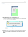
1) Click on Start button and browse to the application folder (FFGSM).
2) Click on the application folder and select the application name (FFGSM.exe).
Note: Please wait patiently because it might take a couple of minutes for the application to start.
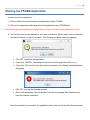
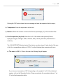
3) The first time you run the application, you need to activate it. Please make sure you have the
internet connection in order to activate it. The following activation dialog box appears.
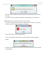
Click „OK‟ to activate the application.
If you click „CANCEL‟, the dialog box will close and the application will not run.
If you click „OK‟ but don‟t have the internet connection, the following message window
will appear.
Click „OK‟ to close the message window.
Re-run the application if you would like to activate the program later whenever you
have the internet connection.
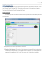
Once the activation is successful, the application starts and you will see the following screen:
Page |5
Page |6
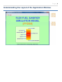
Understanding the Layout of the Application Window.
Page |7
File Menu
The file menu contains several options some of which are also available as icons in the
toolbar right underneath the file menu.
1) New Case: Opens a new project. Same as the 'New Case Icon'.
If a project is in progress and the New Case option is selected from the File menu or the New
Case Icon is clicked, the following message appears:
Click 'Yes' if you want to abort the current case and open a new case.
Click „No‟ if you want to stay with the current case.
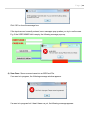
2) Open Case: Opens a previously saved case in the MS-Excel format and loads all the values
from the file to the input fields. The following dialog box appears when the Open Case is
selected:
Page |8
If you select a case and click on „Open‟ the following dialog box appears and once the data is
loaded, the dialog box automatically closes.
If you click „Cancel‟ in the Select File to Open Dialog box above, the following message
window appears:
Click „OK‟ to close the message box.
If a case is already in progress, clicking the „Open Case‟ Icon displays the following message:
Page |9
If you select „YES‟ the „Select File to Open‟ dialog box opens again allowing you to select a
file to open.
If you select „NO‟ the message box closes without making changes to the current case.
3) Run Case: Runs the case if all the inputs are correctly entered.
If no case is in progress and the „Run Case‟ is selected from the file menu or by clicking on
the „Run Case Icon‟ the following message box is displayed:
Click the 'OK' button to close the message window.
If a case is in progress and all the inputs are correctly entered, the following message
appears:
As soon as the calculations are done, the „Run Case‟ message box closes and the following
message appears:
P a g e | 10
Click „OK‟ to close the message box.
If the inputs are not correctly entered, error messages pop up when you try to run the case.
E.g. If the USER NAME field is empty, the following message pops up.
4) Save Case: Saves a current case into an MS-Excel File.
If no case is in progress, the following message window appears:
If a case is in progress but it hasn‟t been run yet, the following message appears:
P a g e | 11
If a case has been successfully run, then it is ready to be saved. The following dialog box
appears:
A filename appears by default in the „File name:‟ section. This default filename is the
combination of the user name and case number. You can either use the default file name or a
different file name of your own. Click „Save‟ to save the case.
If you click „Cancel‟ the following message box appears.
P a g e | 12
5) Close Case: Closes a currently active case. The following dialog box appears upon selecting
this open.
Click „YES‟ to close the current case.
Click „NO‟ to stay with the current case.
6) Exit: Exits the FFGSM Application. The following dialog box appears:
Click „Yes‟ to exit the application or click „No‟ to stay in the application.
P a g e | 13
Starting a New Project
In order to start a new project:
1) Select File New, OR
2) Click on the New Icon on the toolbar.
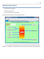
The following window appears in the gray project window.
As it can be seen from the figure that there are various tabs (which are explained next) that
will allow us to navigate to the respective area and enter the inputs required to perform calculations.
P a g e | 14
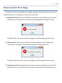
Some Common Error Flags
Error flags have been incorporated into the gasifier application which will pop up if the inputs are
entered incorrectly. The following are some common error flags:
1) Non-Numeric Input: All the input fields take numeric values only. Entering any non-numeric
data like a text or a combination of numbers and text generates the following error flag.
Clicking the 'OK' button closes the error message and sets the respective field to empty.
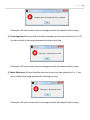
2) Pressure Input: All the pressure fields accept positive pressure values. Anything that
corresponds to a negative or vacuum pressure genets the following error flag.
Clicking the 'OK' button closes the error message and sets the respective field to empty.
3) Temperature Input: All temperature fields accept temperature values that are greater than
the absolute zero. Any value less than the absolute zero generates the following error flag.
P a g e | 15
Clicking the 'OK' button closes the error message and sets the respective field to empty.
4) Percentage Input: All input fields that take percentage input only take values from 0 to 100.
Any value outside of that range generates the following error flag.
Clicking the 'OK' button closes the error message and sets the respective field to empty.
5) Molar Ratio Input: All input fields that take ratio as input only take values from 0 to 1. Any
value outside of that range generates the following error flag.
Clicking the 'OK' button closes the error message and sets the respective field to empty.
P a g e | 16
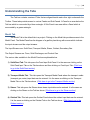
Understanding the Tabs
The Tab bar contains a series of Tabs that are aligned beside each other right underneath the
Toolbar. These tabs provide access to various Panels and Sub-Panels. A Panel is an area below the
Tab bar which is surrounded by a blue rectangle. A Sub-Panel is an area within a Panel which is
surrounded by a green rectangle.
Model Tab
The Model Tab is the default tab in a project. Clicking on the Model tab provides access to the
Model Panel. The Model Panel has the diagram of a gasifier plant along with arrows which indicate
the input streams and the output streams.
The Input Streams are: Solid Feed, Transport Media, Steam, Oxidant, Secondary Gas.
The Output Streams are: Fines, Solid Discharges, and Product Gas.
The various tabs available in the Model Panel are explained below.
1) Solid Feed Tab: This tab opens the Feed Input Sub-Panel. It is the same as clicking on the
Solid Feed Input Tab on the Tab bar above and then clicking on Feed Input Tab. (Click here
to go to the Solid Feed section)
2) Transport Media Tab: This tab opens the Transport Media Panel where the transport media
(transport gas, water) input data can be entered. It is the same as clicking on the Transport
Media Tab on the Tab bar above. (Click here to go to the Transport Media section)
3) Steam: This tab opens the Steam where steam input data can be entered. It is the same as
clicking on the Steam on the Tab bar above. (Click here to go to the Steam section)
4) Oxidant Tab: This tab opens the Oxidant Panel where the oxidant input data can be entered.
It is the same as clicking on the Oxidant Tab on the Tab bar above. (Click here to go to the
Oxidant section)
P a g e | 17
5) Secondary Gas Tab: This tab opens the Secondary Panel. This feature has been disabled
for the Trial version. (Click here to go to the Secondary Gas section)
6) Gasifier Tab: This tab opens the Gasifier Panel where the gasifier input data can be entered.
It is the same as clicking on the Gasifier Tab on the Tab bar above. (Click here to go to the
Gasifier section)
7) Fines Tab: This tab opens the Fines and Discharges Sub-Panel where the fines input data
and discharges input data can be entered. It is the same as clicking on the Solid Feed Tab on
the Tab bar above and then clicking on the Fines and Discharges Tab. (Click here to go to the
Fines & Discharges section)
8) Discharges Tab: Same as the Fines Tab. This tab opens the Fines and Discharges SubPanel where the fines input data and discharges input data can be entered. It is the same as
clicking on the Solid Feed Input Tab on the Tab bar above and then clicking on the Fines and
Discharges Tab. (Click here to go to the Fines & Discharges section)
P a g e | 18
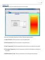
Gasifier Tab
The Gasifier Tab opens the Gasifier Panel which is shown below:
The inputs in the Gasifier Operating Conditions Table are explained below:
1) System Pressure: Enter the pressure inside the gasifier plant.
2) Bed Temperature: Enter the temperature of the gasifier plant.
3) Fines Temperature: Enter the temperature at which the fines are exiting from the gasifier.
4) Discharges Temperature: Enter the temperature at which the discharges are exiting from
the gasifier.
5) WGS Equilibrium Temp.: Enter the temperature of the water-gas-shift equilibrium.
P a g e | 19
Solid Feed Input Tab
The Solid Feed Input Tab opens the Solid Feed Input Panel. This panel has two tabs – Feed
Input Tab and Fines & Discharge Tab. These tabs provide access to the respective sub-panels –
Feed Input Sub-Panel and Fines & Discharge Sub-Panel.
Feed Input Tab
The Feed Input Tab is the default tab and the Feed Input Sub-Panel is the default panel and it
is shown below:
The explanation of the various input fields are as follows:
1) Number of feed streams: The number of feed streams can be specified here by selecting a
number from the dropdown list. 1 is the default number of streams. Up to 3 feed streams are
supported by the application. But, for the Trial version, only 1 feed stream is available.
P a g e | 20
2) Feed Type: This drop down list lets the user select the type of feed. The following types of
feed are available:
a) Bituminous
b) Sub-Bituminous
c) Anthracite
d) Lignite
e) Peat
f) Sludge
g) Wood
Once the Feed Type is selected, you can either specify the % wt composition of the various
elements in the feed or click on „LOAD DEFAULT‟ button to load the default compositions.
3) Flow Rate: Enter the mass flow of the feed. The unit is 'lbm/hr'. If a negative feed flow rate is
entered, the following error flag is generated:
P a g e | 21
Clicking the 'OK' button closes the error message and sets the respective field to empty.
4) Temperature: Enter the temperature of the feed.
5) Moisture: Enter the moisture content in the feed as percentage ('%') of the total feed flow.
6) Feed Composition (dry feed): Enter the 'wt %' of the seven main species (Carbon,
Hydrogen, Oxygen, Nitrogen, Sulfur, Chlorine, Ash) in the dry feed flow (total feed flow –
moisture).
The „VALIDATE DATA‟ button checks if the data is correctly entered. It also checks if the sum
of the % wt compositions adds up to 100%. If not the following three scenarios will occur.
a) The sum is > 100 %: If this is the case, the following flag will appear:
If you choose to normalize to 100 % depending on the weight of 'wt %' of the individual
species, click on the 'Normalize' button. Doing so populates the normalized values of 'wt
%' in the feed composition table.
P a g e | 22
b) The sum is < 100 %: If this is the case, the following flag will appear:
If you choose to normalize to 100 %, depending on the weight of 'wt %' of the individual
species, click on the 'Normalize' button. Doing so populates the normalized values of 'wt
%' in the feed composition table.
c) The sum is = 100 %: If the 'wt %' values entered are decimal values then sometimes a
flag might appear saying that the sum of % wt is greater than 100 % (Sum = 100 %) as
shown below. This happens because of the truncation errors and because of the way
computers handle numbers.
If you run into this situation, simply click on 'Normalize' and the values that you entered
(which add up to 100%) won't change at all. In reality they have changed a little bit out in
the very far decimal place but that won't affect the calculation.
The „CLEAR COMP.‟ button clears the wt % composition table if you would like to enter
your own values in that table.
P a g e | 23
Fines and Solid Discharges Tab
The Fines and Discharge Tab opens the Fines and Discharge Sub-Panel. This is the same as
clicking on the Fines Tab or Discharges Tab in the Model Panel.
The descriptions of the input fields are given below:
1) Percent of dry feed going to fines: Enter the % dry feed going into the fines as % wt based
on the wt of the dry feed.
2) Elemental Conversion in the Fines: Enter the % conversion of each species in the fines.
The value for Ash is 0(zero) because it is assumed that Ash doesn't get converted into any
other compound. Trying to change the value for Ash generates the following error flag:
P a g e | 24
Clicking 'OK' closes the error message and sets the value of the Ash field to 0 again.
3) Elemental Conversion in the Discharges: Enter the % conversion of each species in the
fines. The value for Ash is 0 because of the same reason described in 2 above.
P a g e | 25
Transport Media Tab
This tab opens the Transport Media Panel which is shown below. Transport Media Panel
contains the input fields where the data for liquid transport media (like water) and transport gas (like
Nitrogen rich gas) is entered.
The input fields present in the transport media panel are described below.
TRANSPORT GAS INPUT
1) Flow Rate: The molar flow rate of the transport gas in 'lbmol/h'.
2) Temperature: The temperature of the transport gas.
3) Pressure: The pressure of the transport gas.
4) % Nitrogen: The percentage of nitrogen in the transport gas.
P a g e | 26
5) % Oxygen: The percentage of oxygen in the transport gas.
6) % Argon: The percentage of argon in the transport gas.
7) % H2O: The percentage of moisture in the transport gas.
TRANSPORT WATER INPUT
1) Flow Rate: The mass flow rate of the water in 'lbm/h'.
2) Temperature: The temperature of the transport water.
3) Pressure: The pressure of the transport water.
P a g e | 27
Steam Tab
This tab opens the Steam Panel which is shown below. Steam Panel contains the input fields
where the data for steam input has to be entered.
The input fields present in the steam panel are described below:
STEAM INPUT
1) Steam to Carbon molar ratio: The ratio of the number of moles of steam (H2O) supplied to
the number of moles of carbon present in the dry feed. It has no units because it is the ratio of
two same quantities.
2) Temperature: Temperature of the steam.
3) Pressure: Pressure of the steam.
P a g e | 28
Oxidant Tab
This tab opens the Oxidant Panel which is shown below. Oxidant Panel contains the input
fields where the data for oxidant gas has to be entered.
The input fields present in the oxidant panel are described below:
1) Oxygen to Carbon molar ratio: The ratio of the number of moles of oxygen supplied to the
number of moles of carbon present in the dry feed. It has no units because it is the ratio of two
same quantities.
2) Temperature: The temperature of the oxidant gas.
3) Pressure: The pressure of the oxidant gas.
4) % Nitrogen: The percentage of nitrogen in the oxidant gas.
P a g e | 29
5) % Oxygen: The percentage of oxygen in the oxidant gas.
6) % Argon: The percentage of argon in the oxidant gas.
7) % H2O: The percentage of moisture in the oxidant gas.
The „VALIDATE DATA‟ button checks if all the inputs are entered and if the % composition of
the oxidant gas adds up to 100%.
P a g e | 30
Secondary Gas Tab
This option is not available in the trial version.
P a g e | 31
Results Tab
The Results Tab provides access to the Results Panel which is shown below.
Results Panel (showing the Product Side Material Flow)
The Results panel contains the tables for Fines, Discharges and Product Gas which will
display the results.
1) Fines: This table displays the mass flow rate (in 'lbm/h') of the standard species (species that
are present in the feed) in the fines along with the '% wt' of the species.
2) Discharges: This table displays the mass flow rate (in 'lbm/h') of the standard species
(species that are present in the feed) in the dischargesalong with the '% wt' of the species.
3) Product Gas: This table displays the mass flow rate (in 'lbm/h'), mol %, and the molar flow
rate (in 'lbmol/h') of all the product species.
P a g e | 32
The 'Feed Side' Tab provides access to the feed side panel which shows the Feed side Material
Flow as shown below.
Figure 20.0 Results Panel (showing the Feed Side Material Flow)
This panel shows the material flow of the following streams:
1) Transport Gas: This table shows the transport gas mass flow rate in 'lbmol/h'.
2) Feed: The table on the top left shows the total feed mass flow rate (sum total of the mass flow
rates of all the visible feed streams), total moisture flow rate, and the total dry mass flow rate
in the units of 'lbm/h'.
The table next to it shows the total mass flow rate (in 'lbm/h') of the species present in the
feed and their '% wt'.
P a g e | 33
3) Transport Water: This table shows the transport water mass flow rate in 'lbm/h'.
4) Steam: This table shows the steam mass flow rate in 'lbm/h'.
5) Oxidant: This table shows the oxidant molar flow rate in 'lbmol/h'.
6) Secondary Gas: This table shows the secondary gas molar flow rate in „lbmol/h‟.
The 'Product Side' Tab provides access to the product side panel which is shown above.
P a g e | 34
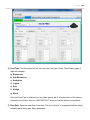
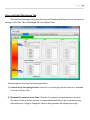
Loading Data from a file into the FFGSM Application
Data can be loaded from an MS-Excel file (if the file with the correct template is selected). A file with
an example case is supplied along with the application package. It is called „Sample Case_0.xlsx‟.
The file contains three sheets: INPUT SHEET, OUTPUT SHEET and REPORT SHEET.
Steps to open (load) a saved case.
1) Click on File Open Case. Alternatively, the Open Case Icon can also be clicked to open the
“Select File to Open” dialog box.
2) Select the correct file and click Open.
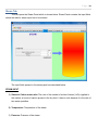
3) The following “Open Case” dialog box appears:
4) It might take a while for the file to load and fill the input fields in the GUI. Once the data is
loaded into the GUI, the dialog box closes automatically.
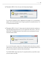
Note: If a file is selected which is not an excel file or if an excel file is selected which is not of the
correct template, the above shown “Open Case” dialog box will appear and won’t close. If you
ever run into that situation, please exit the application and re-run it. In order to avoid that, please
make sure that the file you select to open is an excel file and has the correct template (basically
the excel file that contains the INPUT SHEET and OUTPUT SHEET shown below).
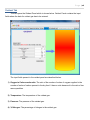
5) After you load the file, you can click the Run Case Icon to run the case.
6) Only after the calculations are correctly performed, you can view the results by clicking on the
„RESULTS‟ tab.
P a g e | 35
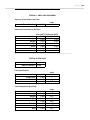
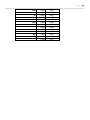
GASIFIER INPUT SHEET
1
GASIFIER OPERATING CONDITIONS
User Name :
Case Num. :
0
0
System Pressure
Bed Temperature
Fines Temperature
Discharge Temperature
WGS Equilibrium Temp.
Gasifier Heat Loss
SOLID FEED INPUT
Number of Feed Streams
STREAM 1
Feed Specification:
Flow Rate
Temperature
Pressure
Moisture
0
0
0
0
Bituminous
Dulong
Feed Type :
HHV Correlations :
lbm/h
F
psig
wt%
Feed Specification:
Flow Rate
Temperature
Pressure
Moisture
Feed Composition (dry feed):
Carbon
0
Hydrogen
0
Oxygen
0
Nitrogen
0
Sulfur
0
Chlorine
0
Ash
0
Total
0
STREAM 3
0
0
0
0
Bituminous
Dulong
Feed Type :
HHV Correlations :
lbm/h
F
psig
wt%
Feed Specification:
Flow Rate
Temperature
Pressure
Moisture
0
0
0
0
Feed Composition (dry feed):
Carbon
Hydrogen
Oxygen
Nitrogen
Sulfur
Chlorine
Ash
Total
0
0
0
0
0
0
0
0
wt%
wt%
wt%
wt%
wt%
wt%
wt%
wt%
Amount of Dry Feed to the Fines:
% wt of dry feed
0
wt%
Feed Composition (dry feed):
Carbon
0
Hydrogen
0
Oxygen
0
Nitrogen
0
Sulfur
0
Chlorine
0
Ash
0
Total
0
wt%
wt%
wt%
wt%
wt%
wt%
wt%
wt%
psig
F
F
F
F
Btu/h
3
STREAM 2
Feed Type :
HHV Correlations :
0
0
0
0
0
0
wt%
wt%
wt%
wt%
wt%
wt%
wt%
wt%
Bituminous
Dulong
lbm/h
F
psig
wt%
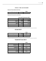
FINES AND DISCHARGES
STREAM 1
STREAM 2
Amount of Dry Feed to the Fines:
% wt of dry feed
0
Elemental Conversion in the Fines:
Fines (wt%) Discharges(wt%)
Carbon
0
Hydrogen
0
Oxygen
0
Nitrogen
0
Sulfur
0
Chlorine
0
Ash
0
0
0
0
0
0
0
0
STEAM INPUT
Steam to C molar ratio
Temperature
Pressure
STREAM 3
Amount of Dry Feed to the Fines:
% wt of dry feed
0
wt%
wt%
Elemental Conversion in the Discharges:
Fines (wt%) Discharges(wt%)
Carbon
0
Hydrogen
0
Oxygen
0
Nitrogen
0
Sulfur
0
Chlorine
0
Ash
0
TRANSPORT GAS INPUT
0 N/A
0F
0 psig
OXIDANT INPUT
* Please enter the INITIAL GUESS for the O2 to feed C molar ratio
O2 to C Molar Ratio *
0 N/A
Temperature
0F
Pressure
0 psig
% Nitrogen
0 mol%
% Oxygen
0 mol%
% Argon
0 mol%
% H2O
0 mol%
TOTAL
0 mol%
Flow Rate
Temperature
Pressure
% Nitrogen
% Oxygen
% Argon
% H2O
TOTAL
0
0
0
0
0
0
0
0
SECONDARY GAS FEED
lbmol/h
F
psig
mol%
mol%
mol%
mol%
mol%
TRANSPORT WATER INPUT
Flow Rate
Temperature
Pressure
0
0
0
0
0
0
0
Elemental Conversion in the Discharges:
Fines (wt%) Discharges(wt%)
Carbon
0
0
Hydrogen
0
0
Oxygen
0
0
Nitrogen
0
0
Sulfur
0
0
Chlorine
0
0
Ash
0
0
0 lbm/h
0F
0 psig
Flow Rate
Temp.
Pressure
0 lbmol/h
0F
0 psig
H2
CO
H2O
CO2
N2
0
0
0
0
0
mol%
mol%
mol%
mol%
mol%
C
CH4
C2H6
C2H4
C6H6
C7H8
C10H8
C6H5OH
H2S
COS
HCl
NH3
HCN
Ar
O2
SO2
S
Cl2
Ash
TOTAL
0
0
0
0
0
0
0
0
0
0
0
0
0
0
0
0
0
0
0
0
mol%
mol%
mol%
mol%
mol%
mol%
mol%
mol%
mol%
mol%
mol%
mol%
mol%
mol%
mol%
mol%
mol%
mol%
mol%
mol%
P a g e | 36
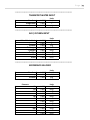
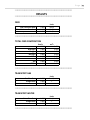
GASIFIER OUTPUT SHEET
TRANSPORT GAS
Gas Flow Rate
Temperature
Pressure
FINES
Units
0 lbmol/h
0F
0 atm
TOTAL SOLID FEED
Total Feed Flow Rate
Total Moisture Flow Rate
Total Dry Feed Flow Rate
Carbon
Hydrogen
Oxygen
Nitrogen
Sulfur
Chlorine
Ash
lbm/h
0
0
0
0
0
0
0
wt%
0
0
0
0
0
0
0
TOTAL
0
0
Units
0 lbm/h
0 lbm/h
0 lbm/h
PRODUCT GAS
TOTAL SOLID FEED COMPOSITION
Carbon
Hydrogen
Oxygen
Nitrogen
Sulfur
Chlorine
Ash
TOTAL
lbm/h wt%
0
0
0
0
0
0
0
0
0
0
0
0
0
0
0
0
TRANSPORT WATER
Water Flow Rate
Temperature
Pressure
Units
0 lbm/h
0F
0 atm
STEAM
Steam Flow Rate
Temperature
Pressure
Units
0 lbmol/h
0F
0 atm
H2
CO
H2O
CO2
N2
C
CH4
C2H6
C2H4
C6H6
C7H8
C10H8
lbm/h mol% lbmol/h
0
0
0
0
0
0
0
0
0
0
0
0
0
0
0
0
0
0
0
0
0
0
0
0
0
0
0
0
0
0
0
0
0
0
0
0
C6H5OH
H2S
COS
HCl
NH3
HCN
Ar
O2
0
0
0
0
0
0
0
0
0
0
0
0
0
0
0
0
0
0
0
0
0
0
0
0
SO2
S
Cl2
Ash
TOTAL
0
0
0
0
0
0
0
0
0
0
0
0
0
0
0
OXIDANT
Oxidant Flow Rate
Temperature
Units
0 lbmol/h
0F
Pressure
0 atm
SECONDARY GAS
Secondary Gas Flow Rate
Temperature
Pressure
Units
0 lbmol/h
0F
0 atm
The Calculated Optimal Oxygen to Carbon Molar Ratio is: 0
SOLID DISCHARGES
Carbon
Hydrogen
Oxygen
lbm/h
0
0
0
wt%
0
0
0
Nitrogen
Sulfur
Chlorine
Ash
TOTAL
0
0
0
0
0
0
0
0
0
0
P a g e | 37
Saving Data from the FFGSM Application to an MS-Excel File
Data from the GUI can be saved in an excel file in the correct template shown above. Data can be
saved only after a case is successfully run. In order to save the data:
1) Select File Save Case or click on the „Save Case‟ Icon on the toolbar.
2) It will prompt for a file name. A default file name appears which is the combination of
username and case number fields.
3) You can either use the default file name or give a different file name, select the location to
save the file and click on „Save‟
4) A dialog box appears:
5) After the excel file is successfully generated, it opens automatically in to the OUTPUT SHEET
section.
P a g e | 38
Formal Report Sheet
The program also generates a complete formal report which includes a detailed description of
all the input and the output streams as a separate tab (REPORT SHEET) in the MS-Excel file.
A sample of the REPORT SHEET is shown below.
P a g e | 39
GASIFIER REPORT
*****************************************************************
User Name :
0
Case Num. :
0
*****************************************************************
GASIFIER OPERATING CONDITIONS
System Pressure
Bed Temperature
Fines Temperature
Discharge Temperature
WGS Equilibrium Temp.
Gasifier Heat Loss
0.000
0.000
0.000
0.000
0.000
0.000
Units
psig
F
F
F
F
Btu/h
*****************************************************************
SOLID FEED INPUT
Number of Feed Streams
3
-------------------------------------------------------------------------------------------------------STREAM 1: FEED SPECS
Feed Type : Bituminous
HHV Correlations : Dulong
Feed Specification:
Flow Rate
Temperature
Pressure
Moisture
0.000
0.000
0.000
0.000
Units
lbm/h
F
psig
wt%
0.000
0.000
0.000
0.000
0.000
0.000
0.000
0.000
Units
wt%
wt%
wt%
wt%
wt%
wt%
wt%
wt%
Feed Composition (dry feed):
Carbon
Hydrogen
Oxygen
Nitrogen
Sulfur
Chlorine
Ash
Total
P a g e | 40
STREAM 1 : FINES AND DISCHARGES
Amount of Dry Feed to the Fines:
% wt of dry feed
0.000
Units
wt%
Elemental Conversion in the Fines:
Fines (wt%) Discharges (wt%)
Carbon
0.000
0.000
Hydrogen
0.000
0.000
Oxygen
0.000
0.000
Nitrogen
0.000
0.000
Sulfur
0.000
0.000
Chlorine
0.000
0.000
Ash
0.000
0.000
-------------------------------------------------------------------------------------------------------STREAM 2: FEED SPECS
Feed Type : Bituminous
HHV Correlations : Dulong
Feed Specification:
Flow Rate
Temperature
Pressure
Moisture
0.000
0.000
0.000
0.000
Units
lbm/h
F
psig
wt%
0.000
0.000
0.000
0.000
0.000
0.000
0.000
0.000
Units
wt%
wt%
wt%
wt%
wt%
wt%
wt%
wt%
Feed Composition (dry feed):
Carbon
Hydrogen
Oxygen
Nitrogen
Sulfur
Chlorine
Ash
Total
P a g e | 41
STREAM 2 : FINES AND DISCHARGES
Amount of Dry Feed to the Fines:
% wt of dry feed
0.000
Units
wt%
Elemental Conversion in the Fines:
Carbon
Hydrogen
Oxygen
Nitrogen
Sulfur
Chlorine
Ash
Fines (wt%) Discharges (wt%)
0.000
0.000
0.000
0.000
0.000
0.000
0.000
0.000
0.000
0.000
0.000
0.000
0.000
0.000
-------------------------------------------------------------------------------------------------------STREAM 3: FEED SPECS
Feed Type : Bituminous
HHV Correlations : Dulong
Feed Specification:
Flow Rate
Temperature
Pressure
Moisture
0.000
0.000
0.000
0.000
Units
lbm/h
F
psig
wt%
0.000
0.000
0.000
0.000
0.000
0.000
0.000
0.000
Units
wt%
wt%
wt%
wt%
wt%
wt%
wt%
wt%
Feed Composition (dry feed):
Carbon
Hydrogen
Oxygen
Nitrogen
Sulfur
Chlorine
Ash
Total
P a g e | 42
STREAM 3 : FINES AND DISCHARGES
Amount of Dry Feed to the Fines:
% wt of dry feed
0.000
Units
wt%
Elemental Conversion in the Fines:
Carbon
Hydrogen
Oxygen
Nitrogen
Sulfur
Chlorine
Ash
Fines (wt%) Discharges (wt%)
0.000
0.000
0.000
0.000
0.000
0.000
0.000
0.000
0.000
0.000
0.000
0.000
0.000
0.000
*****************************************************************
STEAM INPUT
Steam to C molar ratio
Temperature
Pressure
0.000
0.000
0.000
Units
N/A
F
psig
*****************************************************************
TRANSPORT GAS INPUT
Flow Rate
Temperature
Pressure
% Nitrogen
% Oxygen
% Argon
% H2O
TOTAL
0.000
0.000
0.000
0.000
0.000
0.000
0.000
0.000
Units
lbmol/h
F
psig
mol%
mol%
mol%
mol%
mol%
P a g e | 43
*****************************************************************
TRANSPORT WATER INPUT
Flow Rate
Temperature
Pressure
Units
lbm/h
F
psig
0.000
0.000
0.000
*****************************************************************
AIR / OXYGEN INPUT
O2 to C Molar Ratio
Temperature
Pressure
% Nitrogen
% Oxygen
% Argon
% H2O
TOTAL
0.000
0.000
0.000
0.000
0.000
0.000
0.000
0.000
Units
N/A
F
psig
mol%
mol%
mol%
mol%
mol%
*****************************************************************
SECONDARY GAS FEED
Flow Rate
Temp.
Pressure
0.000
0.000
0.000
Units
lbmol/h
F
psig
0.000
0.000
0.000
0.000
0.000
0.000
0.000
0.000
0.000
0.000
0.000
0.000
Units
mol%
mol%
mol%
mol%
mol%
mol%
mol%
mol%
mol%
mol%
mol%
mol%
Elements
H2
CO
H2O
CO2
N2
O2
C
Cl
S
H2S
COS
HCl
P a g e | 44
NH3
HCN
Ar
CH4
C2H6
C2H4
C6H6
C7H8
C10H8
C6H5OH
Ash
SO2
TOTAL
0.000
0.000
0.000
0.000
0.000
0.000
0.000
0.000
0.000
0.000
0.000
0.000
0.000
mol%
mol%
mol%
mol%
mol%
mol%
mol%
mol%
mol%
mol%
mol%
mol%
mol%
P a g e | 45
*****************************************************************
RESULTS
*****************************************************************
FEED
Total Feed Flow Rate
Total Moisture Flow Rate
Total Dry Feed Flow Rate
0.000
0.000
0.000
Units
lbm/h
lbm/h
lbm/h
*****************************************************************
TOTAL FEED COMPOSITION
Carbon
Hydrogen
Oxygen
Nitrogen
Sulfur
Chlorine
Ash
TOTAL
lbm/h
0.000
0.000
0.000
0.000
0.000
0.000
0.000
0.000
wt%
0.000
0.000
0.000
0.000
0.000
0.000
0.000
0.000
*****************************************************************
TRANSPORT GAS
Gas Flow Rate
Temperature
Pressure
0.000
0.000
0.000
Units
lbmol/h
F
atm
*****************************************************************
TRANSPORT WATER
Water Flow Rate
Temperature
Pressure
0.000
0.000
0.000
Units
lbm/h
F
atm
*****************************************************************
P a g e | 46
*****************************************************************
STEAM
Steam Flow Rate
Temperature
Pressure
0.000
0.000
0.000
Units
lbmol/h
F
atm
*****************************************************************
OXIDANT
Oxidant Flow Rate
Temperature
Pressure
0.000
0.000
0.000
Units
lbmol/h
F
atm
*****************************************************************
SECONDARY GAS
Secondary Gas Flow Rate
Temperature
Pressure
0.000
0.000
0.000
Units
lbmol/h
F
atm
*****************************************************************
FINES
Carbon
Hydrogen
Oxygen
Nitrogen
Sulfur
Chlorine
Ash
TOTAL
lbm/h
0.000
0.000
0.000
0.000
0.000
0.000
0.000
0.000
wt%
0.000
0.000
0.000
0.000
0.000
0.000
0.000
0.000
*****************************************************************
P a g e | 47
*****************************************************************
SOLID DISCHARGES
Carbon
Hydrogen
Oxygen
Nitrogen
Sulfur
Chlorine
Ash
TOTAL
lbm/h
0.000
0.000
0.000
0.000
0.000
0.000
0.000
0.000
wt%
0.000
0.000
0.000
0.000
0.000
0.000
0.000
0.000
*****************************************************************
PRODUCT GAS
H2
CO
H2O
CO2
N2
C
CH4
C2H6
C2H4
C6H6
C7H8
C10H8
C6H5OH
H2S
COS
HCl
NH3
HCN
Ar
O2
SO2
S
Cl2
Ash
TOTAL
lbm/h
0.000
0.000
0.000
0.000
0.000
0.000
0.000
0.000
0.000
0.000
0.000
0.000
0.000
0.000
0.000
0.000
0.000
0.000
0.000
0.000
0.000
0.000
0.000
0.000
0.000
mol%
0.000
0.000
0.000
0.000
0.000
0.000
0.000
0.000
0.000
0.000
0.000
0.000
0.000
0.000
0.000
0.000
0.000
0.000
0.000
0.000
0.000
0.000
0.000
0.000
0.000
lbmol/h
0.000
0.000
0.000
0.000
0.000
0.000
0.000
0.000
0.000
0.000
0.000
0.000
0.000
0.000
0.000
0.000
0.000
0.000
0.000
0.000
0.000
0.000
0.000
0.000
0.000