1
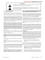
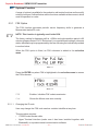
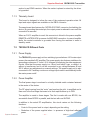
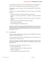
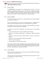
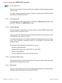
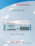
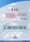
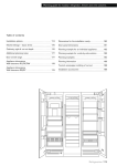
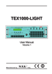
Superior Broadcast LLC SBFM150-SS User Manu als Superior Broadcast LLC 1 8 2 0 8 P r e s t o n R d . S u i t e D 9 - 2 9 7 , D a l l a s , T X 7 5 2 5 2 . w w w. s b p - t v. c o m Superior Broadcast SBFM150SS Transmitter S u p e r i o r B ro a d cast where the B est Cost L ess C a l l u s t o d a y. We want to talk to You Superior Broadcast 18208 Preston Rd, Suite D9-297, Dallas, TX 75252 Tel: 972-473-2577 | Email: [email protected] www.sbp-tv.com All rights reserved. Printed and bound in the U.S.A . No part of this manual may be reproduced, memorized or transmitted in any form or by any means, electronic or mechanic, including photocopying, recording or by any information storage and retrieval system, without written permission of the copyright owner. Superior Broadcast Jimmie Joynt Tel: 972-473-2577 | Email: [email protected] 1 8 2 0 8 P r e s t o n R d . S u i t e D 9 - 2 9 7 , D a l l a s , T X 7 5 2 5 2 . w w w. s b p - t v. c o m SBFM150SS Transmitte r User Manual Superior Broadcast Superior Boadcast SBFM150SS Transmitter ELETTRONICA TEX30/50/100/150/300/502/702-LCD Table of Contents 1. 2. 3. 3.1 3.2 4. 4.1 4.2 4.3 4.4 4.5 4.6 5. 5.1 5.2 5.3 5.4 5.5 6. 6.1 7. 7.1 7.2 7.3 7.4 7.5 Superior Broadcast Preliminary Instructions 1 Warranty 1 First Aid 2 Treatmentofelectricalshocks 2 TreatmentofelectricalBurns 2 General Description 3 Unpacking 3 Features 3 FrontalPanelDescription 5 RearPanelDescription 6 ConnectorsDescription 7 TechnicalDescription 9 Quick guide for installation and use 10 Preparation 10 Firstpower-onandsetup 12 Operation 14 ManagementFirmware 16 OptionalFunction 22 IdentificationandAccesstotheModules 24 IdentificationoftheModules 24 Working Principles 28 TEX30/50/00/50/300/502/702LCDCommonParts28 TEX30LCDDifferentParts 29 TEX50/100/50LCDDifferentParts 30 TEX300LCDDifferentParts 32 TEX502/702LCDDifferentParts 33 SBFM150SS Transmitter User Manual Superior Broadcast SBFM150SS Transmitter This page was intentionally left blank ii SBFM150SS Transmitte r User ManualRev. 1.0 - 22/11/10 Superior Broadcast User Manual ATVST-CNV Superior Boadcast SBFM150SS Transmitter IMPORTANT The lightning flash with arrowhead, within a triangle, is intended to alert the user of the presence of dangerous voltage that may constitute a risk of electric shock. The exclamation point within an equilateral triangle is intended to alert the user to the presence of important operating and maintenance (servicing) instructions in the literature accompanying the equipment. Preliminary Instructions 1. Preliminary 1. Instructions Operation of this equipment in a residential area may cause WIRING: Thisradio device has a connection ground on the power cord and interference, in whichtocase the user may be required on the chassis. Check that they are correctly connected. to take adequate measures. • General foreword• General The equipment in object is to considering for uses, Warnings specifications and dataambient contained provided Operate with The this device in a residential canherein causeare radio disturbs; installation and maintenance from “trained” or “qualified” staff, they conscious information only to and subject changes measures. without This equipment should only be operated, installed and in this case, itforcan be demanded theare user to taketoadequate of the risks connected to operatebyon electronic and electrical circuits electrical. notice. R.V.R. Television disclaims all warranties, maintained “trained” or “qualified” personnel who are familiar Specificationsprior and informations contained in this manual are furnished for express or implied.While R.V.R. Television attempts to with risks involved in working on electric and electronic circuits. information only, and are subject to change at any time without notice, and provide accurate information, it cannot accept responsibility “Trained” personnel who have technical knowledge The “trained” definition meansmeans staff with technical knowledge about the use of of should not be or construed as a commitment by Superior Broadcast. liability for any errors or inaccuracies in this manual, equipment operation and who the equipment and with responsibility regarding theare ownresponsible safety and for thetheir otherown including the products and the software described herein. safety andunder that of unqualified personnel under not qualified staff safety place hisother directed surveillance in caseplaced of works The SuperiorR.V.R. Broadcast assumesreserves no responsability for any errors Television the right or to liability make changes to their supervision when working on the equipment. on the equipment. The “qualified” definition means staff with instruction and or inaccuracies that may appear in this manual, including the products and equipment design and/or specifications and to this manual “Qualified” means personnel who are trained in and software described it;and it reserves the right to modify the design and/ experience about the use of the equipment and with responsibility regarding at anyintime without prior notice. experienced with equipment operation and who are or the technical specifications of the product and this manual without notice. the own safety and the other not for qualified staffsafety safetyand place under his directed responsible their own that of other unqualified • Notice concerning product intended purpose and use surveillance in case personnel of works onplaced the equipment. under their supervision when working on limitations. • Warning regarding the use designated and the use limitations of the the equipment. This product is a radio transmitter suitable for frequencyproduct. WARNING: The machine can be equipped with an ON/OFF switch modulation audio radio broadcasting. Its operating which could not remove completely voltages insidemay the be machine. is WARNING: Residual voltage presentItinside are notradio harmonised in designated userbroadcasting countries. This product frequencies is an transmitter indicated for the audio the equipment even when the ON/OFF switch is set to necessary to have disconnected the feeding cord, or to have switched B e f o r emodulation. o p e r a t i nItg uses t h i sworking e q u i pfrequencies m e n t , u s ethat r m u snot t service in frequency are Off. Before servicing the equipment, off the control panel, before to execute technical operations,disconnect making surethe obtain a licence to use radio spectrum from the harmonized in the states of designated user. The user of this product must power cord or switch off the main power panel and in the designated userof country. himself that the safety connection to ground is connected. The technical obtain from thecompetent Authority forauthority spectrum management in the state designated make sure the safety earth connection is connected. Operating frequency, transmitter power and other interventions that Some expect service the equipment inspection with circuits under user the appropriate authorization to use the radio spectrum, before putting situations may require inspecting the of the transmission system are subject to voltage must be carry out from trained and qualified staff in presence of in exercise thischaracteristics equipment. The working frequency, the transmitter power, let equipmentwithlivecircuits.Onlytrainedandqualified restrictions as specified in the licence. a second trained person that itmay is ready removing in be personnel workto onintervene the equipment livevoltage and shall alone other specifications of the transmission system are subject to limitation assisted by a trained person who shall keep ready to case of need. and definited in the authorization obtained. disconnect power supply at need. 2. Warranty Superior Broadcast doesn’t assume responsibility for injury or damage 2. Warranty Superior Broadcast guarantees absence of this manufacturing La R.V.R. Television warrants product to defect be freeand fromthe resulting from improper procedures or practices by untrained/unqualified R.V.R. Television shall not be liable for injury to persons or defects inproducts, workmanship and itsprovided proper operation subject to good operation for the within the terms and conditions. personnel in the handling of this unit. the limitations set forth in the supplied Terms and Conditions. damage to property resulting from improper use or operation Please read the terms carefully, because the purchase of the product or Please read the Terms and Conditions carefully, as purchase by trained/untrained and qualified/unqualified persons. acceptance of order confirmation, constitutes acceptance of the terms and of the product or acceptance of the order acknowledgement WARNING: The equipment is not water resistant and an infiltration could acceptance of conditions, the Terms and visit Conditions. conditions. Forimply the last legal terms and please our web site seriously compromise its correct operation. In order to prevent fires or For the latest and conditions, visit ourfor web WARNING: The equipment is not water resistant. www.sbp-tv.com) wich mayupdated also beterms changed, removedplease or updated any at WWW.RVR.IT. The web site may be modified, removed electric shocks, doAny notwater expose the equipment to rain, infiltrations or reason withoutsite entering the enclosure might impair proper prior notice. Warranty will be void in cases of opened products, or updated for any reason whatsoever without prior notice. humidity. operation. To prevent the risk of electrical shock or physical damage, misuse, modification, repairandbyvoid unauthorised persons, The warranty will become null in the event the fire,donotexposethisequipmenttorain,drippingor product the product is physically carelessness and usingenclosure the productisforopened, other purpose than its intended use. In is repaired byin unauthorised moisture. Please observe all local codes and fire protection standards during installation case of defect,damaged, proceed like described the following:persons or is used for purposes other than its intended use, as well as in the event and use of this unit. Please observe local codes and fire prevention rules when of improper use, unauthorised changes or neglect. In the event defect iswhere found,you follow this procedure: 1. Contact the dealer or adistributor purchased the unit. installing and operating this equipment. Describe1theContact problemthe and, so that a possiblewho easysold solution can be WARNING: The equipment has to its inside exposed parts to risk of electric seller or distributor the equipment; detected. provide a description of the problem or malfunction for shock, always disconnect WARNING: power before This opening covers or removing any part equipment contains exposed the event a quick fix is available. of this unit. live parts involving an electrical shock hazard. Always Dealers and Distributors are Distributors supplied with all theprovide information problems Sellers and can theabout necessary disconnect power supply before removing any covers information to troubleshoot the most frequently and usually they can repair the unit quickerencountered than what the or other parts of the equipment. Fissures and holes are supplied for the ventilation in order to assure a reliable that may occur problems. Normally, Sellers errors and Distributors canbyoffer a manufacturer could do. Very often installing are discovered dealers. faster repair service than the Manufacturer would. Please efficacy of the product that forslits protect heating, Ventilation anditself holesfrom are excessive provided to ensurethese reliable note that Sellers can pinpoint problems due to wrong fissures do not haveoperation to be obstructed or to be covered. The fissures be or and prevent overheating; do notdoesn’t obstruct 2. If your dealer cannot help you, contact Superior Broadcast and explain installation. cover these slits. Do not obstruct the ventilation slits under obstructed in no case. The product must not be incorporated in a rack, unless the problem. Ifyour it is decided to return unitcontact to the factory, Superior 2 If Seller cannot helpthe you, R.V.R. Television any circumstances. must not beinstructions incorporated it is supplied with a suitable ventilation orThe that product the manufacturer’s Broadcast will mail you a regular authorization with all the necessary and describe the problem; if our staff deems it are been followed. in a rack unless adequate ventilation is provided or the yougoods; will receive an authorisation to return instructions toappropriate, send back the manufacturer’s instructions are followed closely. the equipment along with suitable instructions; WIRING: This equipment can irradiate radio frequency energyand if it’s 3. When you authorization, you the can authorisation, return the unit. you Packmay it 3 receive Whenthe you have received R N I N G : contained T h i s e q in u ithe p mmanual e n t c aand n rlocal a d i a t e return the unit. Pack theusing unit carefully before shipment; carefully for the shipment, preferably the original packing and seal not installed following theWA instructions the original packaging whenever possible and seal radiofrequency energy and, if not installed in compliance the package use perfectly. Theperfectly. customerThe always assumes theall risks of of loss regulations it could generate interferences in radio communications the package customer bears risks with manual instructions and applicable regulations, (i.e., loss (i.e., R.V.R. shall not be liable for loss or damage) may cause interference with radio communications. WARNING: This equipment is fitted with earth connections both in the power cord and for the chassis. Make sure both are properly connected. Superior Broadcast User Manual until the package reaches the R.V.R. factory. For this reason, we recommend insuring the goods for their full value. Returns must be sent on a C.I.F. basis (PREPAID) to the address stated on the authorisation as specified by the R.V.R. Service Manager. 1 Rev. 1.0 - 01/07/08 SBFM150SS Transmitter 1 User / 44Manual Superior Broadcast SBFM150SS Transmitter Superior Broadcast. is never responsible for damage or loss), until the package reaches R.V.R. premises. For this reason, we suggest you to insure the goods for the whole value. Shipment must be effected C.I.F. (PREPAID) to the address specified by Superior Broadcast’s service manager on the authorization DO NOT RETURN UNITS WITHOUT OUR AUTHORIZATION AS THEY WILL BE REFUSED Figure 5 • In case of only one rescuer, 15 compressions alternated to two breaths. • If there are two rescuers, the rythm shall be of one brath each 5 compressions. • Do not interrupt the rythm of compressions when the second person is giving breath. • Call for medical assistance as soon as possible. 4 Be sure to enclose a written technical report where mention all the problems found and a copy of your original invoice establishing the starting date of the warranty. Replacement and warranty parts may be ordered from the following address. Be sure to include the equipment model and serial number as well as part description and part number. Superior Broadcast 18208 Preston Rd, Suite D9-297 Dallas, TX 75252 Tel: 972-473-2577 3.1.2 If victim is responsive The personnel employed in the installation, use and maintenance of the device, shall be familiar with theory and practice of first aid. 3. First Aid 3.1 Treatment of electrical shocks • • • • Keep them warm. Keep them as quiet as possible. Loosen their clothing (a reclining position is recommended). Call for medical help as soon as possible. 3.2 Treatment of electrical Burns 3.1.1 If the victim is not responsive 3.2.1 Extensive burned and broken skin Follow the A-B-C’s of basic life support. • Place victim flat on his backon a hard surface. • Open airway: lift up neck, push forehead back (Figure 1). • • • • • Cover area with clean sheet or cloth. Do not break blisters, remove tissue, remove adhered particles of clothing, or apply any salve or ointment. Treat victim for shock as required. Arrange transportation to a hospital as quickly as possible. If arms or legs are affected keep them elevated. If medical help will not be available within an hour and the victim is conscious and not vomiting, give him a weak solution of salt and soda: 1 level teaspoonful of salt and 1/2 level teaspoonful of baking soda to each quart of water (neither hot or cold). Allow victim to sip slowly about 4 ounces (half a glass) over a period of 15 minutes. Figure 1 • clear out mouth if necessary and observe for breathing Discontinue fluid if vomiting occurs. • if not breathing, begin artificial breathing (Figure 2): tilt head, pinch nostrils, make airtight seal, four quick full breaths DO NOT give alcohol. Remember mouth to mouth resuscitation must be commenced as soon as possible. 3.2.2 Less severe burns • Apply cool (not ice cold) compresses using the cleansed available cloth article. clothing, or apply salve or ointment. • Apply clean dry dressing if necessary. • Treat victim for shock as required. • Arrange transportation to a hospital as quickly as possible. • If arms or legs are affected keep them elevated. Figure 3 Figure 4 2 Do not break blisters, remove tissue, remove adhered particles of Figure 2 • Check carotid pulse (Figure 3); if pulse is absent, begin artificial circulation (Figure 4) depressing sternum (Figure 5). SBFM150SS Transmitte r User Manual • Superior Broadcast ELETTRONICA TEX30/50/100/150/300/502/702LCD Superior Boadcast SBFM150SS Transmitter 4. General Description The TEX30/50/100/150/300/502/702LCD, manufactured by R.V.R. Elettronica SpA,areexcitersforFrequencyModulatedaudio broadcastinginafrequency modulationabletotransmitinthebandbetween87.5and108MHz,instepof10 KHz,withanRFoutputpoweradjustableuptoamaximumof30,50,100,150, 300,500and700Wrespectivelyintoa50Ohmstandardload. TheTEX30/50/100/150/300/502/702LCDaredesignedtobeingcontainedintoa 19”rackboxof2HE. 4.1 Unpacking Thepackagecontains: 1TEX30LCD,TEX50LCD,TEX100LCD,TEX150LCD,TE300LCD,TEX502LCD orTEX702LCD 1UserManual 1Mainspowercables ThefollowingaccessoriesarealsoavailablefromYourR.V.R.Dealer: • Accessories,sparepartsandcables 4.2 Features Theseexciterscontainalow-passfilterthatreducestheharmonicemissionto providedforbyinternationalstandards(CCIR,FCCorETSI)andcanbeconnected directlytotheantenna. TwomajorfeaturesofTEX30/50/100/150/300/502/702LCDarecompactdesign anduser-friendliness.Designisbasedonamodularconcept:thedifferentfunctions areperformedbymodulesthat,forthemostpart,areconnectedthroughmaleand facilitatesmaintenanceandmodulereplacement. TheRFpowersectionoftheTEX30LCDfeaturesaMOSFETmoduledelivering upto30Woutputpower,theTEX50/100/150LCDfeaturesaMOSFETmodule deliveringupto150Woutputpower,theTEX300LCDfeaturesaMOSFETmodule delivering up to 300W output power, whereas the TEX502LCD features two MOSFETmoduleswithupto350Woutputpowereach;theTEX702LCDfeatures aMOSFETmoduledeliveringupto800Woutputpower Operatingfrequencystabilityisensuredbyatemperature-compensatedreference oscillatorandismaintainedbyaPLL(PhaseLockedLoop)system.Theexciters willgointofrequencylockwithin30secondsafterpower-on. Superior Broadcast The TEX30/50/100/150/300/502/702LCDcanoperatethroughoutthefrequency bankwithnoneedforcalibrationorset-up. 3 SBFM150SS Transmitter User Manual TEX30/50/100/150/300/502/702LCD ELETTRONICA Superior Broadcast SBFM150SS Transmitter AnLCDonthefrontpanelandapush-buttonboardprovideforuserinterfacing withthemicroprocessorcontrolsystem,whichoffersthefollowingfeatures: •Outputpowersetup. •Operatingfrequencysetup. •Poweroutputenable/disable. • PowerGoodfeature(User-selectableoutputpoweralarmthreshold). • Measurementanddisplayoftransmitteroperatingparameters. • Communication with external devices such as programming or telemetry systemsviaRS232serialinterfaceorI2C. FourLEDsonthefrontpanelprovidethefollowingstatusindications:ON,LOCK, FOLDBACKandRFMUTE. Theexcitershaveaninputfortheexternal24Vccsupply.Thisauxiliarysupply source, that can be realized by the user with the help of rescue batteries, is automaticallyusedincaseofACvoltageabsence. The exciter management firmware is based on a menu system. User has four navigationbuttonsavailabletobrowsesubmenus:ESC, , ,edENTER. The rear panel features the mains input connectors, as well as audio input connectorsandRFoutputconnector,telemetryconnector,protectionfusesand twoinputsforsignalsmodulatedontosubcarriersbysuitableexternalcoders,such asRDS(RadioDataSystem)signalscommonlyusedinEurope. SBFM150SS Transmitte r User Manual 4 Superior Broadcast ELETTRONICA 4.3 TEX30/50/100/150/300/502/702LCD Superior Boadcast SBFM150SS Transmitter Frontal Panel Description [1]AIRFLOW [2]ON [3]LOCK [4]FOLDBACK Airflowfortheforcedventilation. GreenLED,litwhentheexciterisworking. Greenled,litwhenthePLLislockedontheworkingfrequency. YellowLED,litwhenthefoldbackfunctionisoperating(automatic reductionofthedeliveredRFpower). [5]R.F.MUTE YellowLED,litwhentheexciter’spoweroutputisinhibitedbyan externalinterlockcommand. [6]CONTRAST Displaycontrastadjustingtrimmer(onthetopoftheequipment). [7]ESC Pushbuttontoexitfromamenu. [8] Pushbuttontomoveinthemenusystemandtomodifythe parameters. [9] Pushbuttontomoveinthemenusystemandtomodifythe parameters. [10]ENTER Pushbuttontoconfirmaparameterandtoenterinamenu. [11]DISPLAY Liquidcrystalsdisplay. [12]POWER ON/OFFswitch. Superior Broadcast 5 SBFM150SS Transmitter User Manual Superior Broadcast SBFM150SS Transmitter TEX30/50/100/150/300/502/702LCD 4.4 Rear Panel Description [1]PLUG [2]VENTOLA [3]R.F.OUTPUT [4]24VDCIN- [5]24VDCIN- [6]INTERLOCKOUT [7]FWDEXT.AGC [8]RFLEXT.AGC [9]REMOTE [10]GSMANT [11]PHASEADJ [12]MODE/MPXIMP [13]SCA/RDS [14]MPX [15]MPXADJ [16]SCA/RDSADJ [17]RIGHTADJ [18]RIGHT [19]FUSEBLOCK [20]R.F.TEST [21]MODEM [22]I2CBUS [23]RS232 [24]SERVICE [25]EXTREF10MHz [26]PREEMPHASIS SBFM150SS Transmitte r User Manual /34 ELETTRONICA VDEplugformainssupply. Fanfortheforcedventilationoftheexciter. RFoutputconnector,N-type,50Ω. External24Vdcsupplyinput.Negative(black).Onlyfor TEX30/50/100/150LCD. External24Vdcsupplyinput.Positive(red).OnlyforTEX30/ 50/100/150LCD. ConnettoreBNCdiinterlockinuscita:quandol’eccitatore entrainmodalitàstand-by,ilconduttorecentrale, normalmenteflottante,vienepostoamassa Trimmerforthecontrolofthedeliveredpowerinfunctionof theFWDfoldinput. Trimmerforthecontrolofthedeliveredpowerinfunctionof theRFLfoldinput. DB15connectorfortelemetryofthemachine. ReservedforFutureUses-SMAconnectorforGSM Antenna. Pilottonephaseadjustmenttrimmer. Dip-switchtosettheoperationmode(STEREOorMONO) andtheMPXinputimpedance,50Ωor10kΩ. BNCconnector,SCA/RDSunbalancedinput. BNCconnector,MPXunbalancedinput. AdjustmenttrimmerforMPXinput. AdjustmenttrimmerforSCA/RDSinput. AdjustmenttrimmerfortheRightchannelinput. XLRconnector,balancedRightchannelinput. Fusecarrier.Useascrewdrivertoaccessthefuse. RFtestoutput,approx.13dBmwrttheRFoutputpower level.Notsuitableforspectralanalysis. DB9connectorconnectedtoGSMmodem(onlywith telemetryoption). Normallynotused,orusedforcustomizedfunctions(only withtelemetryoption). DB9connectorfordirectserialcommunicationormodem (onlywithtelemetryoption). DB9connectorforinterconnectionwithotherdevices andforfactoryparametersprogramming(onlyforfactory programming). Fineregulationtrimmerforfrequencytransmission. Optionally,SyncsignalinputBNCconnectorforexternal devices. Dip-switchtosetthepreenphasysat50or75μs.The preenphasyssettingisrelevantonlyfortheLeftandRight inputsinstereomodeandforthemonoinputinmonomode, Rev. 1.1 - 15/11/10 6 Superior Broadcast User Manual Superior Boadcast SBFM150SS Transmitter TEX30/50/100/150/300/502/702LCD ELETTRONICA whileMPXinputisunaffectedbythissetting. [27]19kHzPILOTOUTBNCoutputforthe19kHzpilottone.Thiscanbeusedfor externaldevices(e.g.RDScoders)synchronization. [28]SCA2 BNCconnector,SCA2unbalancedinput. [29]SCA2ADJ AdjustmenttrimmerforSCA2input. [30]LEFT-MONOADJ AdjustmenttrimmerforLeft-Monochannelinput. [31]LEFT-MONO XLRconnector,balancedLeft-Monochannelinput. [32]IMPEDANCE Dip-switchtosetthebalancedinputimpedance,600Ωor 10kΩ. 4.5 Connectors Description 4.5.1 RS232 Type:FemaleDB9 1NC 2SDA 3SCL 4NC 5GND 6NC 7NC 8NC 9NC 4.5.2 Service(for programming of factory parameters) Type:FemaleDB9 1NC 2TX_D 3RX_D 4Internallyconnectedwith6 5GND 6Internallyconnectedwith4 7Internallyconnectedwith8 8Internallyconnectedwith7 9NC 4.5.3 I2CBus Type:MaleDB9 Superior Broadcast 1NC 2TX_D 3RX_D 4Internallyconnectedwith6 5GND 6Internallyconnectedwith4 7Internallyconnectedwith8 8Internallyconnectedwith7 9NC User Manual 7 Rev. 1.1 - 15/11/10 SBFM150SS Transmitter User Manual 7 / 34 Superior Broadcast SBFM150SS Transmitter TEX30/50/100/150/300/502/702LCD ELETTRONICA 4.5.4 Left(MONO)/Right Type:FemaleXLR 1GND 2Positive 3Negative 4.5.5 Remote Type:FemaleDB15 Pin NameTypeMeaning 1 InterlockINBypassespowerifclosedatGND 2ExtAGCFWD IN Ext.signal,1-12V,forpower limitation(AGC) 3 GNDGround 4SDAIICI/OIICcommunicationserialdata 5VPATlm ANLOUTPApowersupplyvoltage3,9VF.S. 6FWDTlm ANLOUTForwardpower3,9VF.S. 7PowerGoodDIGOUTOpencollector,enabledwhenpower exceedsthesetthreshold 8 GNDGround 9 GNDGround 10ExtAGCRFL IN Ext.signal.,1-12V,forpower limitation(AGC) 11SCLIICI/OIICcommunicationclock 12IPATlm ANLOUTPApowersupplycurrent3,9VF.S. 13RFLTlm ANLOUT Reflectedpower3,9VF.S. 14Oncmd DIGINOnegroundedpulse(500ms) enablespowersupply 15OFFcmd DIGINOnegroundedpulse(500ms) disablespowersupply SBFM150SS Transmitte r User Manual 8 Superior Broadcast Superior Boadcast SBFM150SS Transmitter TEX30/50/100/150/300/502/702LCD ELETTRONICA 4.6TechnicalDescription Parameters GENERALS Rated output power Frequency range Operational Mode Modulation type Primary Power AC Power Consumption Phisical Dimensions (W x H x D) Weight Environmental Working Conditions Cooling Frequency programmability Frequency stability Pre-emphasis mode Spurious & harmonic suppression Asynchronous AM S/N ratio Synchronous AM S/N ratio MONO OPERATION S/N FM Ratio Frequency Response Total Harmonic Distortion Intermodulation distortion MPX OPERATION Composite S/N FM Ratio Frequency Response Total Harmonic Distortion Intermodulation distortion INTERNAL STEREO CODER OPERATION Stereo S/N FM Ratio Frequency Response Total Harmonic Distortion Intermodulation distortion Stereo separation AUDIO INPUT CONNECTORS Left / Right MPX unbalanced/RDS SCA/RDS OTHER CONNECTORS RF Output RF Monitor Pilot output Interlock Input STANDARD COMPLIANCE TEX30LCD TEX50LCD TEX100LCD 30W 50W 100W 80 ÷ 260 Vac or 24 130 VA / 70W 7 kg ≥ 65 dB (typical 70) ≥ 50 dB (typical 60) TEX300LCD 150W 300W FCC -CCIR - OIRT - JPN Mono, Stereo, Multiplex F3E 115 / 230 ±15% or 28 Vdc 200 VA /100W 330 VA / 212 W 440 VA / 260 W 560 VA / 520 W 483 x 88 x 394 mm 8,5 kg 8,5 kg 8,5 kg 9,5 kg -10 ÷ +50 °C / 95% relative Humidity non condensing Forced, with internal fan From software, with 10 kHz steps ±1 ppm 0/50 (CCIR) μS, 75 (FCC) μS <75 dBc (80 typical) ≥ 60 dB (typical 68) ≥ 50 dB (typical 58) TEX502LCD TEX702LCD 500W 700W 80 ÷ 260 Vac 970VA / 940W 1280VA / 1240W 10 kg 10 kg ≥ 60 dB (typical 65) ≥ 50 dB (typical 55) > 80 dB RMS (typical 85 dB) < ± 0.5 dB 30Hz ÷ 15kHz (typical ± 0.2 dB) < 0.1 % 30 Hz ÷ 15 kHz (typical 0.07 %) < 0.02 % with 1 kHz and 1,3 kHz tones > 80 dB RMS (typical 85 dB) ± 0.2 dB 30Hz ÷ 53kHz / ± 0.5 dB 53kHz ÷ 100 kHz < 0.1% 30Hz ÷ 53kHz < 0.05% with 1 kHz and 1,3 kHz tones > 75 dB RMS (typical 78dB) ± 0.5 dB 30 Hz ÷ 15 kHz < 0.05% 30 Hz ÷ 15 kHz ≤ 0.03% with 1 kHz and 1,3 kHz tones > 50 dB 30 Hz ÷ 15 kHz (typical 55 dB) XLR balanced; Impedance: 10 k or 600 ohm; Level: -13 to +13 dBu BNC unbalanced; Impedance: 10 k or 50 ohm; Level: -13 to +13 dBu 2 x BNC unbalanced; Impedance: 10 k; Level: -8 to +13 dBu N (50 ohm) BNC (- 30dBr referred to RF output ) BNC (1Vpp) BNC EN 60215:1989 EN60215/A1:1992-07 EN60215/A2:1994-09 EN 301 489-1 V1.4.1 (2002-08) EN 301 489-11 V1.2.1 (2002-11) EN 302 018-2 V1.2.1 (2005-06) Safety EMC Radio Superior Broadcast TEX150LCD 9 SBFM150SS Transmitter User Manual TEX30/50/100/150/300/502/702LCD Superior Broadcast SBFM150SS Transmitter ELETTRONICA 5. Quick guide for installation and use This section provides a step-by-step description of equipment installation and configuration procedure. Follow these procedures closely upon first power-on andeachtimeanychangeismadetogeneralconfiguration,suchaswhenanew transmissionstationisaddedortheequipmentisreplaced. Oncethedesiredconfigurationhasbeensetup,nomoresettingsarerequired for normal operation; at each power-up (even after an accidental shutdown), the equipment defaults to the parameters set during the initial configuration procedure. The topics covered in this section are discussed at greater length in the next sections, with detailed descriptions of all hardware and firmware features and capabilities.Pleaseseetherelevantsectionsforadditionaldetails. 5.1 IMPORTANT:When configuring and testing the transmitter in which the equipment is integrated, be sure to have the Final Test Table supplied with the equipment ready at hand throughout the whole procedure; the Final Test Table lists all operating parameters as set and tested at the factory. Prepation 5.1.1 Preliminarychecks Unpacktheexciterandimmediatelyinspectitfortransportdamage.Ensurethat allconnectorsareinperfectcondition. Themainfusecanbeaccessedfromtheoutsideontherearpanel.Extractthe fusecarrierwithascrewdrivertocheckitsintegrityorforreplacement,ifnecessary. Thefusetobeusedisthistype: Fusibile principale TEX30LCD @ 90÷260 Vac (1x) 3.15A tipo 5x20 TEX50/100/150LCD @ 230 Vac/115 Vac (1x) 6.3A tipo 5x20 TEX300/502/702LCD @ 230 Vac/115 Vac (1x) 8A tipo 5x20 Table 5.1: Fuses Provideforthefollowing(applicabletooperatingtestsandputtingintoservice): √ Single-phase 230 VAC or 115 VAC (-15% / +10%) mains power supply for TEX50/100/150LCD,or80÷260VACfull-rangemainspowersupplyforTEX30/ 300/502/702LCD,withadequateearthconnection. √ Foroperatingtestsonly:dummyloadwith50Ohmimpedanceandadequate SBFM150SS Transmitte r User Manual 10 /34 Rev. 1.1 - 15/11/10 10 Superior Broadcast User Manual TEX30/50/100/150/300/502/702LCD Superior Boadcast SBFM150SS Transmitter ELETTRONICA capacity(30WforTEX30LCD,50WforTEX50LCD,100WforTEX100LCD, 150WforTEX150LCD,300WforTEX300LCD,500WforTEX502LCD or 700W forTEX702LCD asaminimum). √ Connectioncablekitincluding: •Mainspowercable •CoaxialcablewithBNCconnectorsforinterlocksignalconnection •RF cable for output to load / antenna (50 Ohm coaxial cable with N-type connector) •Audiocablesbetweentransmitterandaudiosources. 5.1.2 Connections ConnecttheRFoutputofthetransmittertotheantennacableoradummyload capableofdissipatingamplifieroutputpower.Tobeginwith,setexcitertominimum outputpowerandswitchitoff. ConnectthetransmitterINTERLOCKINinputtothematchingINTERLOCKOUT output fitted on R.V.R. Elettronica equipment to act as hybrid couplers. If your equipmentisadifferentbrand,identifyanequivalentoutput. Figure 5.2: connections with amplifier WARNING: Electric shock hazard! Never handle the RF output connector whentheequipmentispoweredonandnoloadisconnected.Injuryordeath may result. EnsurethatthePOWERswitchonthefrontpanelofTEX30/50/100/150/300/502/ 702LCDissetto“OFF”. Superior Broadcast 11 SBFM150SS Transmitter User Manual TEX30/50/100/150/300/502/702LCD Superior Broadcast SBFM150SS Transmitter Theexciterhastwoswitches:oneisembeddedinVDEsocketformainspower cordandinterruptsallmainspowersupplyofthemachine,whilethesecondison thefrontpanelandactsbyinhibitingtheswitchingpowersupplyofthemachine. ELETTRONICA ConnectthemainspowercabletotheMAINSconnectorontherearpanel. Note: the mains must be equipped with adequate earth connection properly connected to the equipment. This is a pre-requisite for ensuring operator safety and correct operation. ConnecttheaudioandRDS/SCAsignalsfromuser’ssourcestothetransmitter inputconnectors. 5.2Firstpower-onandsetup Seguireleistruzioniriportatediseguitonelcasodiprimaaccensioneodopoaver effettuato un cambiamento alla configurazione dell’eccitatore nel quale questo componenteèintegrato. Note:Standard factory settings are RF output power off (Pwr OFF) and regulated output power set to upper limit (unless otherwise specified by customer). 5.2.1 Power-on When you have performed all of the connections described in the previous paragraph, power on the exciter using the suitable power switch on the front panel. 5.2.2 Powercheck EnsurethattheONLEDturnson.Equipmentnameshouldappearbrieflyonthe display,followedbyforwardpowerandmodulationreadings.IftheRFoutputis disabled,thosereadingswillbezero. WhenthePLLlockstooperatingfrequency,theLOCKLEDwillturnon. 5.2.3 HowtoenabletheRFoutput Checkoutputpowerlevelandsetittomaximumlevel(unlessithasalreadybeen set) from the Power Setup menu that you will have accessed by pressing the followingsequenceofkey:ESC(opensDefaultMenu)⇒ENTER(holddownfor 2seconds)⇒SET⇒usekeystosetbartoupperlimit(figure5.2-menu2). CheckthestateofthePwroutputpowerbytheFncmenu.IfitissettoOFF,press ENTERtobringtheselectiontoON. SBFM150SS Transmitte r User Manual 12 Superior Broadcast ELETTRONICA TEX30/50/100/150/300/502/702LCD Superior Boadcast SBFM150SS Transmitter 5.2.4 Controllodellivellodipotenzadiuscita Note:The exciter incorporates Automatic Gain Control (AGC) and output power is modulated based on the power level set by the user and actual operating conditions, such as temperature, reflected power and other parameters. Please read section 5.3 for more details of RF power modulation. AccessthePowerSetupMenupressingthefollowingkeysintheorder: ESC(opensDefaultMenu)⇒ENTER (holddownfor2seconds) Usethekeys and intheSETmenutosetexciteroutputpower;thesettingbar atthesideofSETprovidesagraphicindicationofpowersetting;pleaseconsider thattheforwardpowerreadoutprovidedonthedisplay(FWD:xxxxW)reflects actualoutputpowerreading,whichmaybelowerthanregulatedpowersupply whenAutomaticGainControlisrunninginpowersupplylimitationmode (pleasereadsection5.3aboutRFpowersupplymodulationformoredetails). Note: Output power may be set using the PwrOFF control. In this condition, the output power readout (Fwd) on the display will read 0 (zero); the SET bar will reflect any adjustments you make using the keys and provides a graphic indication of how much power supply will be delivered the moment you return to PwrOn state. 5.2.5 ChangingthePower Goodalarmthreshold ChangeForwardPowerGoodalarmsettingPgDfromtheFncmenuasdesired (factorysettingis50%). 5.2.6 SettingequipmentI2Caddress Change the IIC address in the MIX (Miscellaneous) menu as desired (factory settingis01). 5.2.7 Adjustmentsandcalibration The only manual adjustments are the level adjustments and the audio mode adjustment. Therearpanelholdsthetrimmersforallexciterinputs.Trimmeridentificationis printedontherearpanel.Inputsensitivitycanbesetwithinthelimitssetoutin thetablesbelowthroughthetrimmers: Superior Broadcast 13 SBFM150SS Transmitter User Manual TEX30/50/100/150/300/502/702LCD ELETTRONICA Superior Broadcast SBFM150SS Transmitter Inputsensitivity: Input SCA1/ RDS SCA2 MPX Left/ Mono Right Figure6.2 Trimmer [13] [16] [28] [14] [29] [15] [31] [30] [18] [17] Sensitivity Notes -8÷+13dBu Inputlevelfor7,5kHzoveralldeviation (-20dB) -8÷+13dBu -13÷+13dBu Inputlevelfor75kHzoveralldeviation -13÷+13dBu (0dB) -13÷+13dBu When setting input sensitivity, please consider that the default menu reports instantaneousmodulationlevelandanindicatorprovidesa75kHzreading.To ensure correct adjustment, apply a signal with the same level as user’s audio broadcastmaximumlevelandthenadjustusingthetrimmeruntilinstantaneous deviationmatchesthe75kHzreading. Tosetsubcarrierinputlevels,youmayusethesameprocedureandoption“x10” availableintheFncmenu.Withthisoption,modulationlevelismultipliedbyafactor of10,whichmeansthatdefaultmenubarmeterreflectsa7.5kHzdeviation. A special menu with separate indications of Left and Right channel levels and relatingindicatorsofnominallevelsformaximumdeviation(75kHz)isprovided. •Preemphasis: ON 1 ON 2 3 4 50ms 1 2 3 4 75ms •LandR(XLRtype)inputimpedance: ON 1 Switch1:RXLRinputimpedance,ON=600W,OFF=10kW 2 Switch2:LXLRinputimpedance,ON=600W,OFF=10kW •MPXinputoperationmode/impedance: ON 1 Switch1:ModeofoperationON=Mono,OFF=Stereo 2 Switch2:MPXinputimpedance,ON=50W,OFF=10kW 5.3Operation NOTE:Forbetterclarity,onlythetypicalscreensofTEX702LCDarereported below.TEX30/50/100/150/300/502LCDscreenslookthesameexceptthatfull scalevaluesaredifferent. 1)PowerontheexciterandensurethattheONlightturnson.Equipmentname should appear briefly on the display, quickly followed by modulation and forwardpowerreadings(Menu1),providedthattheexciterisdeliveringoutput power. SBFM150SS Transmitte r User Manual 14 /34 Rev. 1.1 - 15/11/10 14 Superior Broadcast User Manual TEX30/50/100/150/300/502/702LCD Superior Boadcast SBFM150SS Transmitter ELETTRONICA Menu 1 1b)Tomodifypowerlevelsetting,holddowntheENTERbuttonuntilopening thepowersetupmenu. Theeditscreenwilllooklikethis: Menu 2 NexttoSETindication,abarprovidesagraphicdisplayofpresetoutputpower. Thefilledportionofthebarisproportionaltosetpowerlevel. Example ≅ 700W in uscita (mod.TEX702LCD) ≅ 500W in uscita (mod.TEX502LCD) ≅ 300W in uscita (mod.TEX300LCD) Barra piena 100% potenza di uscita ≅ 150W in uscita (mod.TEX150LCD) ≅ 100W in uscita (mod.TEX100LCD) ≅ 50W in uscita (mod.TEX50LCD) ≅ 30W in uscita (mod.TEX30LCD) ≅ 175W in uscita (mod.TEX702LCD) ≅ 125W in uscita (mod.TEX502LCD) ≅ 75W in uscita (mod.TEX300LCD) 25% potenza di uscita 1/4 della barra ≅ 700W in uscita (mod.TEX702LCD) ≅ 37,5W in uscita (mod.TEX150LCD) ≅ 25W in uscita (mod.TEX100LCD) ≅ 12,5W in uscita (mod.TEX50LCD) ≅ 7,5W in uscita (mod.TEX30LCD) User Manual Superior Broadcast Rev. 1.1 - 15/11/10 15 15 / 34 SBFM150SS Transmitter User Manual TEX30/50/100/150/300/502/702LCD Superior Broadcast SBFM150SS Transmitter ELETTRONICA Thebottomlineprovidesinstantaneouspowerreading(700WforTEX702LCD shownhere),pressbutton toincreaselevel,press todecreaseit.When youhaveachievedthedesiredlevel,pressENTERtoconfirmandexitthedefault menu.Pleasenotethatthesettingisstoredautomatically;inotherwords,ifyou pressESCordonotpressanykeysbeforethepresettimetimesout,thelatest powerlevelsetwillberetained. NOTE:Thisfeaturepreventstheequipmentfromdeliveringmaximumpower assoonasoutputisenabledfrommenu4,orintheeventtheequipmentis alreadysettoONwhenyouenergiseit. 2)Ensurethattheequipmentisnotinalocked-outstate.PressESCtocallup theselectionscreen(menu3).HighlightFncandpressENTERtoconfirmand accesstheselectedmenu(menu4). IfPWRissettoOFF,i.e.poweroutputisdisabled,movecursortoPWR.Press ENTERandlabelwillswitchtoON,i.e.poweroutputisenabled. PressESC twicetogobacktothedefaultmenu(menu1). 3)Finetunepowersettingfrommenu2(seedescriptionofitem1b)untilachieving thedesiredvalue. WARNING:Equipmentiscapableofdeliveringmorethanratedoutputpower (30/50/100/150/300/500/700 W for TEX30/50/100/150/300/502/702LCD respectively);however,neverexceedthespecifiedpowerrating. NOTE:Ifpowerissetto0WinthePowerSetupMenu,theINTERLOCKOUT contactisactivatedandanyexternalappliancesconnectedtoitareimmediately inhibited. Next, you can review all operating parameters of the equipment through the managementfirmware. Normally, the equipment can run unattended.Any alarm condition is handled automaticallybythesafetysystemorissignalledbytheLEDindicatorsonthe panelorbydisplaymessages. NOTE: Standard factory settings are output power set to upper limit (unless otherwisespecifiedbycustomer)andOFF. 5.4ManagementFirmware TheequipmentfeaturesanLCDwithtwolinesby16charactersthatdisplaysa setofmenus.Thefigurebelowprovidesanoverviewofequipmentmenus. Thesymbolslistedbelowappearintheleftportionofthedisplayasappropriate: (Cursor)-Highlightsselected(i.e.accessible)menu. (Filledarrow)-Editableparametermarker.Thissymbolappearsinmenusthat takeupmorethantwolinestoaidbrowsing. (Threeemptyarrows)-Parameterisbeingedited. SBFM150SS Transmitte r User Manual 1 /34 Rev. 1.1 - 15/11/10 16 Superior Broadcast User Manual TEX30/50/100/150/300/502/702LCD Superior Boadcast SBFM150SS Transmitter ELETTRONICA (Empty arrow) - Current line marker; the parameter in this line cannot be edited.Thissymbolappearsinmenusthattakeupmorethantwolinestoaid browsing. Menu2 Menu1 Predefinedmenu PowerAdjustmentMenu Menu3 SelectionMenu Menu4 OperationMenu Menu5 PowerMenu Menu6 PowerAmplifierMenu Menu7 SettingsMenu Menu8 MiscellaneousMenu Menu9 VersionsMenu Menu10 ChannelsMenu Figure 5.2 Whenthedisplayisoff,touchinganykeywillturnonbacklighting. Whenthedisplayison,pressingtheESCbuttonfromthedefault menu(menu1) callsuptheselection screen(menu3),whichgivesaccesstoallothermenus: Menù 3 If the temperature alarm is enabled and the alarm threshold is exceeded, the followingscreenwillbedisplayed(onlyifyouareinthedefaultscreen): Superior Broadcast 17 State 1 SBFM150SS Transmitter User Manual TEX30/50/100/150/300/502/702LCD Superior Broadcast SBFM150SS Transmitter ELETTRONICA Assoonasoperatingconditionsarerestored,poweroutputisre-enabledwiththe samesettingsinusepriortothealarmcondition. Under20kHz,nomodulationoccurs.Afterapresettimeofabout5minutes(not editable),aNOAUDIOconditionisindicatedinthemainscreen,butpowerisnot inhibited. State 2 Togainaccesstoasubmenu,selectmenuname(nameishighlightedbycursor) usingbuttonorandpresstheENTERbutton. Toreturntothedefault menu(menu1),simplypressESCagain. 5.4.1 OperationMenu(Fnc) Inthismenu,youcantoggleexciterpoweroutputOn/Off,setdeviation display mode and the threshold rate for Forward (PgD) or Reflected (PgR) Power Good. To edit an item, highlight the appropriate line using the and buttons and then press and hold the ENTER button until the command is accepted. Thisway,PwrsettingistoggledbetweenOnandOffandModsettingistoggled between“x1”and“x10”.ToeditthePowerGoodrate,simplyselectitem“PgD”or “PgR”andedititsvalueusingtheUPandDOWNbuttons;finally,pressENTER toconfirm. Menu 4 PwrEnables(ON)ordisables(OFF)exciterpoweroutput. Mod Modifiesmodulationdisplay(togglesbetween“x1”and“x10”).In“x10” mode,instantaneousdeviationindicationismultipliedbyafactorof10, andthebarmeteronthedefaultmenuwillreflect7.5kHzinsteadof SBFM150SS Transmitte r User Manual 18 Superior Broadcast TEX30/50/100/150/300/502/702LCD Superior Boadcast SBFM150SS Transmitter ELETTRONICA 75kHz.Thisdisplaymodeisconvenientwhenyouwishtodisplaylow deviationlevels,suchasthosecausedbypilottoneorsubcarriers. PgD ModifiesPowerGoodthresholdforforwardpower.ThePowerGoodrate isapercentofequipmentratedpower(30/50/100/150/300/500/702W forTEX30/50/100/150/300/502/702LCDrespectevely),notofforward output power. This means that this threshold set at 50% will give 15/25/50/75/150/250/350W,respectively,regardlessofsetpowerlevel. ThePowerGoodfeatureenablesoutputpowercontrolandreporting. When output power drops below set Power Good threshold, the equipmentchangesthestateofpin[7]oftheDB15“Remote”connector locatedontherearpanel. PgR ModifiesPowerGoodthresholdforreflectedpower.ThePowerGood rateisapercentofequipmentratedpower(3/5/10/15/30/50/70Wfor TEX30/50/100/150/300/502/702LCD respectevely), not of reflected outputpower.Thismeansthatthisthresholdsetat5%willgive0,15 /0,25/0,50/0,75/1,5/2,5/3,5 W , respectively, regardless of set power level.ThePowerGoodfeatureenablesoutputpowercontrolandalarm management. NOTE:ThisalarmdoesnottripanycontactsintheDB15“Remote”connectorand isonlyavailableinsystemsequippedwithtelemetry. 5.4.2 Powermenu(Pwr) Thisscreenholdsallreadingsrelatedtoequipmentoutputpower: Menu 5 FwdForwardpowerreading. Rfl Reflectedpowerreading. Note that these are readings, rather than settings, and cannot be edited (note theemptytriangle).Tochangepowersetting,gotothedefault menuasoutlined earlier. Superior Broadcast 19 SBFM150SS Transmitter User Manual TEX30/50/100/150/300/502/702LCD Superior Broadcast SBFM150SS Transmitter ELETTRONICA 5.4.3 PowerAmplifier(P.A)Menu Thisscreenismadeupoffourlinesthatcanbescrolledusingthe buttonsandshowsthereadingsrelatingtofinalpowerstage: and Menu 6 Notethatthesearereadings,ratherthansettings,andcannotbeedited(notethe emptyarrow). VPAVoltagesuppliedbyamplifiermodule. IPACurrentdrawofamplifiermodule. Eff Efficiencybasedonratioofforwardpowertoamplifiermodulepower, inpercent(FWDPWR/(VpaxIpa)%). TmpEquipmentinternaltemperaturereading. 5.4.4 SetupMenu(Set) Thismenuletsyouviewandsetoperatingfrequency. Menu 7 F1 Operatingfrequencysetup.Setanewfrequencyvalueandthenpressthe ENTERbuttontoconfirmyourselection;theexciterunlocksfromcurrent frequency(theLOCKLEDturnsoff)andwilllocktothenewoperating frequency(LOCKturnsbackonagain). IfyoupressESCorletthepresettimetimeout,thepreviousfrequency settingisretained. SBFM150SS Transmitte r User Manual 20 Superior Broadcast TEX30/50/100/150/300/502/702LCD ELETTRONICA Superior Boadcast SBFM150SS Transmitter 5.4.5 MiscellaneousMenu(Mix) ThismenuletsyousetequipmentaddressinanI2Cbusserialconnection: Menu 8 IIC I2Caddresssetting.TheI2Cnetworkaddressbecomessignificantwhen theexciterisconnectedinanRVRtransmissionsystemthatusesthis protocol.Donotchangeitunlessstrictlyrequired. 5.4.6 VersionMenu(Vrs) Thisscreenholdsequipmentversion/releaseinformation: Menu 9 Notethatthesearereadings,ratherthansettings,andcannotbeedited(notethe emptyarrow). RelFirmwarereleaseinformation. DatReleasedate. TabShowstableloadedinthememory. 5.4.7 ChannelsMenu(L&R) Rightandleftchannelinputlevelsaredisplayedashorizontalbarsasshownin thefigurebelow. Thebarmeterreflectsthelevelcorrespondingtoa100%deviationforeachchannel andprovidesaconvenientreferencewhensettingaudiochannelinputlevels. Menù 10 L R Manual SuperiorUser Broadcast LeftchannelVmeter. RightchannelVmeter.. Rev. 21 1.1 - 15/11/10 21 / 34 SBFM150SS Transmitter User Manual TEX30/50/100/150/300/502/702LCD Superior Broadcast SBFM150SS Transmitter ELETTRONICA 5.5OptionalFunction Arangeofoptionsisavailablefortheproducttoaddcertainfunctionsand/ormodify existingfunctions.Outlinedbelowarethefunctionsavailableatthemoment,which mustbespecifiedonorder. 5.5.1 FSKOption The FSK function generates periodic carrier frequency shifts to generate a MorsecodedstationIDcode. NOTE:ThisfunctionistypicallyusedintheUSA. Thefactorysettingforfrequencyshiftis+10KHzandcoderepetitionperiodis60 minutes(pleasecontactR.V.R.Elettronicaifyouneeddifferentsettings),whereas stationidentifiedmaybeprogrammedbytheuserfollowingtheindicationsprovided insectionbelow. When the FSK option is fitted, an FSK submenu is added to the selection menu. Menu 11 PresstheENTERkeywhenFSKishighlightedintheselection menutoaccess theFSKsubmenu: Menu 12 FSK Enables/disablesFSKcodetransmission. Cod ShowstheMorsecodesentnormally. 5.5.1.1 ChangingtheIDcode UsermaychangetheFSKcodeusedasastationidentifieratanytime. Thisprocedurerequires: •1RS232male-femalecable; •Hyper Terminal interface (make sure it has been installed together with Windows®)orequivalentserialcommunicationsoftware. SBFM150SS Transmitte r User Manual 22 /34 Rev. 1.1 - 15/11/10 22 Superior Broadcast User Manual Superior Boadcast SBFM150SS Transmitter TEX30/50/100/150/300/502/702LCD ELETTRONICA Abriefdescriptionoftheprocedureisprovidedbelow: •ConnectthePCserialportCOMtotheSERVICEconnectorontherearpanel ofTEX30/50/100/150/300/502/702LCDusingastandardMaleDB9-Female DB9serialcable. •Powerontheexciter; •Launchtheserialcommunicationsoftware; •Setcommunicationparametersasfollows: BaudRate:19200 DataBit:8 Parity:None StopBit:1 Flowcontrol:None; •ActivateCaps-LockthroughthecommunicationsoftwareandsendstringCODE followedbythe6-characterstationIDcodefollowedbyEnter. NOTE: To be treated as valid, the code must be made up of 6 alphanumeric charactersandmustcontainnoblankspaces;ifacknowledgedasvalid,codeis echoedbacktotheterminal,illegalcodesarenotechoed. 5.5.2 PowerUP/DOWNOption ThePowerUP/DOWNoptionmodifiesthesignalreceivefunctionforthesignals presentatthetelemetryconnector. RF section on / off control signals are treated as control signals for RF output powerleveltoallowforUP/DOWNsetting. TheUPorDOWNcommandisprovidedbyswitchingthecorrespondingsignalat theconnectortogroundforatleast500mS(pinfeaturesinternalpull-uptopower supply). ConfigurationofDB15Ftelemetryconnector(Remote): PinStandardFunction UP/DOWNPowerFunction 14OncmdUpcmd Enables the RF power supply Increases the RF power supply 15OffcmdDowncmd Superior Broadcast Disables the RF power supply 23 Reduces the RF power supply SBFM150SS Transmitter User Manual TEX30/50/100/150/300/502/702LCD ELETTRONICA Superior Broadcast SBFM150SS Transmitter 6. IdentificationandAccesstotheModules 6.1 IdentificationoftheModules TheTEX30/50/100/150/300/502/702LCDismadeupofvariousmoduleslinked toeachotherthroughconnectorssoastomakemaintenanceandanyrequired modulereplacementeasier. 6.1.1 TEX30LCDUpperview Thefigurebelowshowstheequipmentupperviewwiththevariouscomponents pointedout. figure 8.1 [1]MainBoard&StereoCoderCard(SLMBDTEXLC07 & SLCTC30V03) [2]PanelCard(SL007PC3001) [3]TelemetryCard(SLTLMTXLCD03) [4] ControlCard&PowerAmplifier(SL037BI1004 &SLPA30WMOS02) [5]PowerSupply(FLY100SMD) SBFM150SS Transmitte r User Manual 24 Superior Broadcast ELETTRONICA TEX30/50/100/150/300/502/702LCD Superior Boadcast SBFM150SS Transmitter 6.1.2 TEX50/100/150LCDUpperview Thefigurebelowshowstheequipmentupperviewwiththevariouscomponents pointedout. figure 8.2 [1]MainBoard&StereoCoderCard(SLMBDTEXLC07 & SLCTC30V03) [2]PanelCard(SL007PC3001) [3]TelemetryCard(SLTLMTXLCD03) [4] ControlCard&PowerAmplifier(SL045DR1003 &SLPA150WMOS) [5]PowerSupply(PSL300) Superior Broadcast 25 SBFM150SS Transmitter User Manual Superior Broadcast SBFM150SS Transmitter TEX30/50/100/150/300/502/702LCD ELETTRONICA 6.1.3 TEX300LCDUpperview Thefigurebelowshowstheequipmentupperviewwiththevariouscomponents pointedout. figure 8.3 [1]MainBoard&StereoCoderCard(SLMBDTEXLC07 & SLCTC30V03) [2]PanelCard(SL007PC3001) [3]TelemetryCard(SLTLMTXLCD03) [4] ControlCard&PowerAmplifier(SL045DR1003 &SL045RF1002) [5]PowerSupply(PSL00) SBFM150SS Transmitte r User Manual 26 Superior Broadcast Superior Boadcast SBFM150SS Transmitter ELETTRONICA TEX30/50/100/150/300/502/702LCD 6.1.4 TEX502/702LCDUpperview Thefigurebelowshowstheequipmentupperviewwiththevariouscomponents pointedout. figure 8.4 [1]MainBoard&StereoCoderCard(SLMBDTEXLC07 & SLCTC30V03) [2]DriverCard(SL175DR1002) [3]PanelCard(SL007PC3001) [4]TelemetryCard(SLTLMTXLCD03) [5] BiasCard,ControlCard,LowPassFilterCard&PowerAmplifier-TEX502LCDmodel (SL046BI1001,SL175BI1001, SL175LP1002 &SL154RF3001) BiasCard,CintrolCard,LowPassFilterCard&PowerAmplifier-TEX702LCDmodel (SL046BI1001,SL175BI1001, SL175LP1002 &SL154RF2002) [6]PowerSupply(PSL5021) Superior Broadcast 27 SBFM150SS Transmitter User Manual TEX30/50/100/150/300/502/702LCD Superior Broadcast SBFM150SS Transmitter ELETTRONICA 7. Working Principles 7.1 TEX30/50/100/150/300/502/702LCD Common Parts 7.1.1 Panelboard Thepanelboardcontainsthemicrocontroller(PIC18F452)thatimplementsthe equipment control software, the display and the other components needed to interfacewiththeuser. Theboardisconnectedwiththeothermachinemodules,bothforpowersupply distributionandforthecontrolandmeasures. 7.1.2 Mainboard Themainboardcarriesoutthefollowingfunctions: • AudioandSCAinputtreatment • Generationofcarrierfrequency • Modulation • R.F.amplification(Driver) Theboardalsofeaturesastereophoniccoder. 7.1.2.1 Audioinputsection Theaudioinputsectioncontainsthecircuitsthatperformthefollowingfunctions: • Inputimpedanceselection • 15kHzfilteringoftheleftandrightchannel • StereophonicCoding • Monochannelpreemphasis • Mono,MPXandSCAchannelmixing • Clipper(limitsthemodulatingsignallevelsothatthefrequencydeviationdoes notexceed75kHz) • Modulatingsignalmeasurement 7.1.2.2 PLL/VCOsection Thisboardsectiongeneratesthemodulatedradiofrequencysignal.Itisbasedon aPLLschemethatusesanintegratedMB15E06type. 7.1.2.3 Driversection Beforepassingtothefinalpoweramplifier,theRFsignalispreamplifiedinthis 28 SBFM150SS Transmitte r User Manual Superior Broadcast ELETTRONICA TEX30/50/100/150/300/502/702LCD Superior Boadcast SBFM150SS Transmitter sectionbyanERA3transistor.Whentheexciterisplacedonstand-by,thedriver isby-passed. 7.1.3 Telemetryboard Thisboardisdesignedtoinformtheuseroftheequipmentoperationstate.All inputandoutputsignalsareavailableontheDB15connector. Thesameboardalsofeaturesthe“INTERLOCK”BNCconnectorfordisablingthe device.Bygroundingthecentralpin,theoutputpowerisreducedtozerountilthe connectionisremoved. WhenanR.V.R.amplifierisused,thisconnectorislinkedtothepoweramplifier REMOTEorINTERLOCKbymeansofaBNC-BNCconnection.Incaseofamplifier faults, the central conductor is grounded thus forcing the machine to enter in stand-bymode. 7.2 TEX30LCD Different Parts 7.2.1 PowerSupply TheTEX30LCDpowersupplyunitisaswitching-typeunitwhose+28Vmainoutput powersthemachineÌsRFamplifier.Thepowersupplyalsofeaturesstabilizersfor generatingcontinuous+5Vand+18Vvoltagesforsupplyingtheotherequipment circuits.Notethatthepowersupplyisa“directfrommains”type,orratheritis withoutatransformer,anditcanbeconnectedtoanyvoltagebetween80and 260Vwithoutanyadjustmentsormanualsettings.Thepowersupplyunitisalso connectedto24Vauxiliarycontinuousvoltageinputsusedtoautomaticallybuffer themainspowercutoff. 7.2.2 PowerAmplifier Thefinalpowerstageisenclosedinatotallyshieldedmetalcontainerfastened inthecentreofthedevice. TheRFsignalcomingfromthe“main”cardreachesthepilot,isamplifiedandis thensenttothefinalstagethatseestoitsfinalamplificationsupto30W. The amplifier is made in three stages. The first is made with one BFG35, the secondwiththreeBFG35inparallel,andthelastwithoneBLF245. In addition to the actual RF amplification, this circuit carries out the following functions: • Controlofthepowerlevelinoutput,dependingonthesetting Superior Broadcast • Reduction of the power supplied whenin presence of high-level reflected power 29 SBFM150SS Transmitter User Manual Superior Broadcast SBFM150SS Transmitter TEX30/50/100/150/300/502/702LCD ELETTRONICA • Measures of the forward and reflected power by means of directional couplers • Measuresofthecurrentabsorbedbythepoweramplifier • Measuresofthetemperature • Low-passfilteringoftheRFsignalinoutput ThisboardalsofeaturesanRFsamplingofapproximately-30dBRFwithrespect totheoutput,whichisavailableonaBNCconnectorbelowthetransmitteroutput connector.Thissampleisisusefulforverifyingthecharacteristicsofthecarrier, butnotforverifyingthoseoftheupperharmonics. 7.2.3 ControlBoard ThemainfunctionofthisboardistocheckandcorrecttheMOSFETpolarization voltageoftheRFamplifiersection. Italsoprovidesthemeasurementoftheabsorbedcurrentandcontainsacircuit forsignalingpowersupplyunitfaults. Ifnoalarmsarepresent,thevoltageisadjustedonlydependingonthesetoutput power, with a feedback mechanism based on the reading of the power really delivered(AGC). Thevoltageisalsoaffectedbyotherfactors,suchas: • Excessofreflectedpower. • ExternalAGCsignals(Ext.AGCFWD,Ext.AGCRFL). • Excessoftemperature. • ExcessofabsorbedcurrentfromtheRFmodule. 7.3 TEX50/100/150LCD Different Parts 7.3.1 PowerSupply TheTEX50/100/150LCDpowersupplyunitisaswitching-typeunitwhose+28V mainoutputpowersthemachineÌsRFamplifier.Thepowersupplyalsofeatures stabilizersforgeneratingcontinuous+5V,-15V,+8V,+18Vand-18Vvoltages forpoweringtheotherdevicecircuits.Thepowersupplyunitisalsoconnectedto 24Vauxiliarycontinuousvoltageinputsusedtoautomaticallybufferthemains powercutoff. 7.3.2 PowerAmplifier Thefinalpowerstageisenclosedinatotallyshieldedmetalcontainerfastened inthecentreofthedevice. SBFM150SS Transmitte r User Manual 30 /34 Rev. 1.1 - 15/11/10 30 Superior Broadcast User Manual Superior Boadcast SBFM150SS Transmitter ELETTRONICA TEX30/50/100/150/300/502/702LCD TheRFsignalcomingfromthe“main”cardreachesthepilot,isamplifiedandis thensenttothefinalstagethatseestoitsfinalamplificationsupto150W. Theamplifierismadeintwostages.ThefirstismadewithBLF244andthelast withBLF147. In addition to the actual RF amplification, this circuit carries out the following functions: • Controlofthepowerlevelinoutput,dependingonthesetting • Reduction of the power supplied whenin presence of high-level reflected power • Measures of the forward and reflected power by means of directional couplers • Measuresofthecurrentabsorbedbythepoweramplifier • Measuresofthetemperature • Low-passfilteringoftheRFsignalinoutput OnthiscardisanRFsampleapproximately-30dBcomparedwiththeoutputthatis availableonaBNCconnectorunderneaththeoutputconnectorofthetransmitter. Thissampleisusefulforcheckingthecharacteristicsofthecarrier,butnotofthe higherorderharmonics. 7.3.3 ControlBoard ThemainfunctionofthisboardistocheckandcorrecttheMOSFETpolarization voltageoftheRFamplifiersection. Italsoprovidesthemeasurementoftheabsorbedcurrentandcontainsacircuit forsignalingpowersupplyunitfaults. Ifnoalarmsarepresent,thevoltageisadjustedonlydependingonthesetoutput power, with a feedback mechanism based on the reading of the power really delivered(AGC). Thevoltageisalsoaffectedbyotherfactors,suchas: • Excessofreflectedpower. • ExternalAGCsignals(Ext.AGCFWD,Ext.AGCRFL). • Excessoftemperature. • ExcessofabsorbedcurrentfromtheRFmodule. Superior Broadcast 31 SBFM150SS Transmitter User Manual TEX30/50/100/150/300/502/702LCD Superior Broadcast SBFM150SS Transmitter 7.4 ELETTRONICA TEX300LCD Different Parts 7.4.1 PowerSupply TheTEX300LCDpowersupplyunitisaswitching-typeunitwhose+50Vmain stabilizersforgeneratingcontinuous+5V,+18Vand-18Vvoltagesforsupplying theotherequipmentcircuits.Notethatthepowersupplyisa“directfrommains” type,orratheritiswithoutatransformer,anditcanbeconnectedtoanyvoltage between90and260Vwithoutanyadjustmentsormanualsettings. 7.4.2 PowerAmplifier Thefinalpowerstageisenclosedinatotallyshieldedmetalcontainerfastened inthecentreofthedevice. TheRFsignalcomingfromthe“main”cardreachesthepilot,isamplifiedandis thensenttothefinalstagethatseestoitsfinalamplificationsupto300W. Theamplifierismadeinthreestages.ThefirstismadewithBFG35,thesecond withoneBLF175andthelastwithoneSD2942. In addition to the actual RF amplification, this circuit carries out the following functions: • Controlofthepowerlevelinoutput,dependingonthesetting • Reduction of the power supplied whenin presence of high-level reflected power • Measures of the forward and reflected power by means of directional couplers • Measuresofthecurrentabsorbedbythepoweramplifier • Measuresofthetemperature • Low-passfilteringoftheRFsignalinoutput ThisboardalsofeaturesanRFsamplingofapproximately-60dBRFwithrespect totheoutput,whichisavailableonaBNCconnectorbelowthetransmitteroutput connector.Thissampleisisusefulforverifyingthecharacteristicsofthecarrier, butnotforverifyingthoseoftheupperharmonics. 7.4.3 ControlBoard ThemainfunctionofthisboardistocheckandcorrecttheMOSFETpolarization voltageoftheRFamplifiersection. Italsoprovidesthemeasurementoftheabsorbedcurrentandcontainsacircuit forsignalingpowersupplyunitfaults. 32 Superior Broadcast Ifnoalarmsarepresent,thevoltageisadjustedonlydependingonthesetoutput SBFM150SS Transmitte r User Manual ELETTRONICA Superior Boadcast SBFM150SS Transmitter TEX30/50/100/150/300/502/702LCD power, with a feedback mechanism based on the reading of the power really delivered(AGC). Thevoltageisalsoaffectedbyotherfactors,suchas: • Excessofreflectedpower. • ExternalAGCsignals(Ext.AGCFWD,Ext.AGCRFL). • Excessoftemperature. • ExcessofabsorbedcurrentfromtheRFmodule. 7.5 TEX502/702LCD Different Parts 7.5.1 PowerSupply TheTEX502LCDpowersupplyunitisaswitching-typeunitwhose+50Vmain stabilizersforgeneratingcontinuous+5V,+18Vand-18Vvoltagesforsupplying theotherequipmentcircuits.Notethatthepowersupplyisa“directfrommains” type,orratheritiswithoutatransformer,anditcanbeconnectedtoanyvoltage between90and260Vwithoutanyadjustmentsormanualsettings. 7.5.2 PowerAmplifier Thefinalpowerstageisenclosedinatotallyshieldedmetalcontainerfastened inthecentreofthedevice. TheRFsignalcomingfromthe“main”cardreachesthepilot,isamplifiedandis thensenttothefinalstagethatseestoitsfinalamplificationsupto500W(for TEX502LCDmodel)orupto700W(forTEX702LCDmodel). Theamplificationstageconsistsoftwomainblocks. In addition to the actual RF amplification, this circuit carries out the following functions: • Controlofthepowerlevelinoutput,dependingonthesetting • Reduction of the power supplied whenin presence of high-level reflected power • Measuresofthecurrentabsorbedbythepoweramplifier • Measuresofthetemperature ThisboardalsofeaturesanRFsamplingofapproximately-60dBRFwithrespect totheoutput,whichisavailableonaBNCconnectorbelowthetransmitteroutput connector.Thissampleisisusefulforverifyingthecharacteristicsofthecarrier, butnotforverifyingthoseoftheupperharmonics. Superior Broadcast 33 SBFM150SS Transmitter User Manual Superior Broadcast SBFM150SS Transmitter TEX30/50/100/150/300/502/702LCD ELETTRONICA 7.5.2.1 DriverStageblock ThedrivercardisabletoThecardanddrivers’capableofdeliveringapproximately 15Wofpower. Thedriverstageismadeintwostages.ThefirstismadewithoneBFG35andthe lastwithoneLD-MOSPD57006. 7.5.2.2 FinalStageblock ThefinalstageismadeoftwoMOS-FETSD2932(forTEX502LCDmodel)ortwo MOS-FETSD2942(forTEX702LCDmodel). 7.5.3 ControlBoard ThemainfunctionofthisboardistocheckandcorrecttheMOSFETpolarization voltageoftheRFamplifiersection. Italsoprovidesthemeasurementoftheabsorbedcurrentandcontainsacircuit forsignalingpowersupplyunitfaults. Ifnoalarmsarepresent,thevoltageisadjustedonlydependingonthesetoutput power, with a feedback mechanism based on the reading of the power really delivered(AGC). Thevoltageisalsoaffectedbyotherfactors,suchas: • Excessofreflectedpower. • ExternalAGCsignals(Ext.AGCFWD,Ext.AGCRFL). • Excessoftemperature. • ExcessofabsorbedcurrentfromtheRFmodule. 7.5.4 LowPassFilterCard Thiscardprovidethelow-passfilteringoftheRFsignalinoutputandmeasurethe reflectedandforwardpoweroutput. 7.5.5 BiasCard ThiscardcontrolsthebiasvoltageandcontainsAGCnetworksforforwardpower, reflectedpower,temperature,currentandEXTAGC. SBFM150SS Transmitte r User Manual 34 Superior Broadcast Superior Boadcast SBFM150SS Transmitter ______________________________________________________________________________ ______________________________________________________________________________ ______________________________________________________________________________ ______________________________________________________________________________ ______________________________________________________________________________ ______________________________________________________________________________ ______________________________________________________________________________ ______________________________________________________________________________ ______________________________________________________________________________ ______________________________________________________________________________ ______________________________________________________________________________ ______________________________________________________________________________ ______________________________________________________________________________ ______________________________________________________________________________ ______________________________________________________________________________ ______________________________________________________________________________ ______________________________________________________________________________ ______________________________________________________________________________ ______________________________________________________________________________ ______________________________________________________________________________ ______________________________________________________________________________ ______________________________________________________________________________ ______________________________________________________________________________ ______________________________________________________________________________ 35 SBFM150SS Transmitter User Manual Superior Broadcast ______________________________________________________________________________ Superior Broadcast SBFM150SS Transmitter ______________________________________________________________________________ ______________________________________________________________________________ ______________________________________________________________________________ ______________________________________________________________________________ ______________________________________________________________________________ ______________________________________________________________________________ ______________________________________________________________________________ ______________________________________________________________________________ ______________________________________________________________________________ ______________________________________________________________________________ ______________________________________________________________________________ ______________________________________________________________________________ ______________________________________________________________________________ ______________________________________________________________________________ ______________________________________________________________________________ ______________________________________________________________________________ ______________________________________________________________________________ ______________________________________________________________________________ ______________________________________________________________________________ ______________________________________________________________________________ ______________________________________________________________________________ ______________________________________________________________________________ ______________________________________________________________________________ ______________________________________________________________________________ 36 Superior Broadcast SBFM150SS Transmitte r User Manual ______________________________________________________________________________ Superior Boadcast SBFM150SS Transmitter ______________________________________________________________________________ ______________________________________________________________________________ ______________________________________________________________________________ ______________________________________________________________________________ ______________________________________________________________________________ ______________________________________________________________________________ ______________________________________________________________________________ ______________________________________________________________________________ ______________________________________________________________________________ ______________________________________________________________________________ ______________________________________________________________________________ ______________________________________________________________________________ ______________________________________________________________________________ ______________________________________________________________________________ ______________________________________________________________________________ ______________________________________________________________________________ ______________________________________________________________________________ ______________________________________________________________________________ ______________________________________________________________________________ ______________________________________________________________________________ ______________________________________________________________________________ ______________________________________________________________________________ ______________________________________________________________________________ ______________________________________________________________________________ 37 SBFM150SS Transmitter User Manual Superior Broadcast ______________________________________________________________________________ S u p e r i o r B ro a d cast where the B est Cost L ess C a l l u s t o d a y. We want to talk to You Superior Broadcast Jimmie Joynt Tel: 972-473-2577 | Email: [email protected] 1 8 2 0 8 P r e s t o n R d . S u i t e D 9 - 2 9 7 , D a l l a s , T X 7 5 2 5 2 . w w w. s b p - t v. c o m