1
DOT MATRIX PRINTER
MODEL CBM920II
User’s Manual
R
PE
PA
D
FEE
WEEE MARK
En
,I\RXZDQWWRGLVSRVHWKLVSURGXFWGRQRWPL[ZLWKJHQHUDOKRXVHKROGZDVWH7KHUHLVD
VHSDUDWHFROOHFWLRQV\VWHPVIRUXVHGHOHFWURQLFVSURGXFWVLQDFFRUGDQFHZLWKOHJLVODWLRQXQGHU
WKH:((('LUHFWLYH'LUHFWLYH(&DQGLVHIIHFWLYHRQO\ZLWKLQ(XURSHDQ8QLRQ
Ge
:HQQ6LHGLHVHV3URGXNWHQWVRUJHQZROOHQGDQQWXQ6LHGLHVELWWHQLFKW]XVDPPHQPLWGHP
+DXVKDOWVPOO(VJLEWLP5DKPHQGHU:((('LUHNWLYHLQQHUKDOEGHU(XURSlLVFKHQ8QLRQ
'LUHNWLYH(&JHVHW]OLFKH%HVWLPPXQJHQIUVHSDUDWH6DPPHOV\VWHPHIUJHEUDXFKWH
HOHNWURQLVFKH*HUlWHXQG3URGXNWH
Fr
6LYRXVVRXKDLWH]YRXVGpEDUUDVVHUGHFHWDSSDUHLOQHOHPHWWH]SDVjODSRXEHOOHDYHFYRV
RUGXUHVPpQDJqUHV,OH[LVWHXQV\VWqPHGHUpFXSpUDWLRQGLVWLQFWSRXUOHVYLHX[DSSDUHLOV
pOHFWURQLTXHV FRQIRUPpPHQW j OD OpJLVODWLRQ :((( VXU OH UHF\FODJH GHV GpFKHWV GHV
pTXLSHPHQWVpOHFWULTXHVHWpOHFWURQLTXHV'LUHFWLYH(&TXLHVWXQLTXHPHQWYDODEOH
GDQVOHVSD\VGHO¶8QLRQHXURSpHQQH
/HVDSSDUHLOVHWOHVPDFKLQHVpOHFWULTXHVHWpOHFWURQLTXHVFRQWLHQQHQWVRXYHQWGHVPDWLqUHV
GDQJHUHXVHVSRXUO¶KRPPHHWO¶HQYLURQQHPHQWVLYRXVOHVXWLOLVH]HWYRXVYRXVHQGpEDUUDVVH]
GHIDoRQLQDSSURSULpH
Sp
6LGHVHDGHVKDFHUVHGHHVWHSURGXFWRQRORPH]FOHFRQUHVLGXRVGRPpVWLFRVGHFDUiFWHU
JHQHUDO([LVWHXQVLVWHPDGHUHFRJLGDVHOHFWLYDGHDSDUDWRVHOHFWUyQLFRVXVDGRVVHJ~Q
HVWDEOHFHODOHJLVODFLyQSUHYLVWDSRUOD'LUHFWLYD&(VREUHUHVLGXRVGHDSDUDWRV
HOpFWULFRV\HOHFWUyQLFRV5$((YLJHQWH~QLFDPHQWHHQOD8QLyQ(XURSHD
It
6HGHVLGHUDWHJHWWDUHYLDTXHVWRSURGRWWRQRQPHVFRODWHORDLULILXWLJHQHULFLGLFDVD(VLVWH
XQVLVWHPDGLUDFFROWDVHSDUDWRSHULSURGRWWLHOHWWURQLFLXVDWLLQFRQIRUPLWjDOODOHJLVOD]LRQH
5$(('LUHWWLYD&(YDOLGDVRORDOO¶LQWHUQRGHOO¶8QLRQH(XURSHD
Du
'HSRQHHUGLWSURGXFWQLHWELMKHWJHZRQHKXLVKRXGHOLMNDIYDOZDQQHHUXKHWZLOWYHUZLMGHUHQ(U
EHVWDDW LQJHYROJH GH :(((ULFKWOLMQ 5LFKWOLMQ (* HHQ VSHFLDDO ZHWWHOLMN
YRRUJHVFKUHYHQYHU]DPHOV\VWHHPYRRUJHEUXLNWHHOHNWURQLVFKHSURGXFWHQZHONDOOHHQJHOGW
ELQQHQGH(XURSHVH8QLH
Da
+YLVGXYLOVNLOOHGLJDIPHGGHWWHSURGXNWPnGXLNNHVPLGHGHWXGVDPPHQPHGGLWDOPLQGHOLJH
KXVKROGQLQJVDIIDOG'HUILQGHVHWVHSDUDWLQGVDPOLQJVV\VWHPIRUXGWMHQWHHOHNWURQLVNHSURGXNWHU
LRYHUHQVVWHPPHOVHPHGORYJLYQLQJHQXQGHU:(((GLUHNWLYHWGLUHNWLY(&VRP
NXQHUJ OGHQGHLGHQ(XURS LVNH8QLRQ
Por 6HTXLVHUGHLWDUIRUDHVWHSURGXWRQmRRPLVWXUHFRPROL[RFRPXP'HDFRUGRFRPDOHJLVODomR
TXHGHFRUUHGD'LUHFWLYD5(((±5HVtGXRVGH(TXLSDPHQWRV(OpFWULFRVH(OHFWUyQLFRV
&(H[LVWHXPVLVWHPDGHUHFROKDVHSDUDGRSDUDRVHTXLSDPHQWRVHOHFWUyQLFRVIRUDGH
XVRHPYLJRUDSHQDVQD8QLmR(XURSHLD
Pol -HĪHOL]DPLHU]DV]SR]E\üVLĊWHJRSURGXNWXQLHZ\U]XFDMJRUD]HP]H]Z\Ná\PL
GRPRZ\PLRGSDGNDPL:HGáXJG\UHNW\Z\:((('\UHNW\ZD(&
RERZLą]XMąFHMZ8QLL(XURSHMVNLHMGODXĪ\ZDQ\FKSURGXNWyZHOHNWURQLF]Q\FK
QDOHĪ\VWRVRZDüRGG]LHOQHVSRVRE\XW\OL]DFML
Declaration of Conformity
This printer conforms to the following Standards:
Low Voltage Directive 73/23/EEC, 93/68/EEC and the EMC Directive 89/336/EEC,
92/31/EEC, 93/68/EEC.
LVD : EN60950-1
EMC : EN55022
EN61000-3-2
EN61000-3-3
EN55024
Class A
This declaration is applied only for 230V model.
IMPORTANT: This equipment generates, uses, and can radiate radio frequency energy
and if not installed and used in accordance with the instruction manual, may cause
interference to radio communications. It has been tested and found to comply with
the limits for a Class A computing device pursuant to Subpart J of Part 15 of FCC
Rules, which are designed to provide reasonable protection against such interference
when operated in a commercial environment. Operation of this equipment in a
residential area is likely to cause interference, in which case the user at his own
expense will be required to take whatever measures may be necessary to correct
the interference.
CAUTION: Use shielded cable for this equipment.
Sicherheitshinweis
Die Steckdose zum Anschluß dieses Druckers muß nahe dem Gerät angebracht und
leicht zugänglich sein.
For Uses in Canada
This Class A digital apparatus complies with Canadian ICES-003.
This digital apparatus does not exceed the class A limits for radio noise emissions
from digital apparatus, as set out in the radio interference regulations of the Canadian
department of communications.
Pour L’utilisateurs Canadiens
Cet appareil numérique de la classe A est conforme à la norme NMB-003 du Canada.
Cet appareil numérique ne dépasse pas les limites de carégorie a pour les émissions
de bruit radio émanant d’appareils numériques, tel que prévu dans les réglements
sur l’interférence radio du départment Canadien des communications.
—1—
GENERAL PRECAUTIONS
● Before using this product, be sure to read through this manual. After having read
this manual, keep it in a safe, readily accessible place for future reference.
● The information contained herein is subject to change without prior notice.
● Reproduction or transfer of part or all of this document in any means is prohibited
without permission from Citizen Systems.
● Note that Citizen Systems is not responsible for any operation results regardless
of missing, error, or misprinting in this manual.
● Note that Citizen Systems is not responsible for any trouble caused as a result of
using options or consumables that are not specified in this manual.
● Except explained elsewhere in this manual, do not attempt to service, disassemble,
or repair this product.
● Note that Citizen Systems is not responsible for any damage attributable to
incorrect operation/handling or improper operating environments that are not
specified in this manual.
● Data is basically for temporary use and not stored for an extended period of time
or permanently. Please note that Citizen Systems is not responsible for damage
or lost profit resulting from the loss of data caused by accidents, repairs, tests or
other occurrence.
● If you find loss of information, error, or uncertain matter, please contact your
Citizen Systems dealer.
● If you find any disordered or missing page(s), contact your Citizen Systems dealer
for replacement.
CITIZEN is registered trade mark of CITIZEN WATCH CO., LTD., Japan
CITIZEN es una marca registrada de CITIZEN WATCH CO., LTD., Japón
—1—
SAFETY PRECAUTIONS -WHICH SHOULD BE STRICTLY OBSERVED
In order to prevent injury hazard to operators, third parties or damage to property, special warning
symbols are used in this user’s manual to indicate important items to be strictly observed.
Please be familiar with the following precautions before reading this manual.
● The following describes the degree of hazard and damage that could occur if the printer is
improperly operated by ignoring the instructions indicated by the warning symbols.
Warning
Neglecting precautions indicated by this symbol may
result in fatal or serious injury.
Caution
Neglecting precautions indicated by this symbol may
result in injury or damage to properties.
This symbol is used to alert your attention to important items.
ORDINARYMAINTENANCE
● Make sure to maintain the equipment after switching OFF the power .
● When cleaning the platen of printer mechanism, wipe out the dirty portion by a cotton
pad dipped intoethyl alcohol.
● When cleaning the surface of the main unit case, use soft cloth. In case the dirty
portion can not becleared out by the soft cloth, use wet cloth squeezed tightly.
Absolutely do not use thinners, truculence,benzene or ketene group solvents, or
chemical-impregnated cleaning cloths.
● At least, leave cleaning of the inside of this equipment to your sales shop once a
year. Using thisequipment keeping dirty without cleaning the insidemay cause a fire
or breakage of the equipment.
—2—
WARNING
● Never handle the printer in the manners described below; otherwise, it may be
damaged, get out of order or overheated, possibly causing smoke, fire or electric
shock.
If the printer is damaged or breaks down, be sure to turn off the power, disconnect
the power plug from the wall outlet, and contact your CITIZEN SYSTEMS dealer.
• Do not allow the printer to be subjected to any strong impact or shock, such as
stamping, hitting, dropping, and the like.
• Install the printer in a well-ventilated place. Do not use the printer in such a manner
that its ventilation slots are blocked.
• Do not install the printer in a place like a laboratory where chemical reactions are
expected, or in a place where saltish gases are present in the atmosphere.
• Use the printer only on the specified voltage and frequency.
• Do not connect/disconnect the power cord or data cable by holding the cable. Do
not pull or carry the printer in such a manner that undesirable force is applied to
the cables.
• Do not drop or insert any foreign substances, such as paper clips or pins, into the
printer.
• Avoid using excessively long power cord or data cable or multiple connections.
• Do not use power cord or data cable with a scratch or crack or with poor connection.
• Do not spill any liquid on or spray any chemical-containing liquid over the printer.
If any liquid is spilled on the printer, turn it off, disconnect the power cord from the
wall outlet, and contact your CITIZEN SYSTEMS dealer.
• Do not disassemble or modify the printer in any manner; otherwise, a fire or electric
shock may result.
● The plastic bag the printer came in must be disposed of properly or kept away from
children. Wearing it over the head may lead to suffocation.
—3—
PRECAUTIONS FOR INSTALLATION
● Do not use or store the printer in a place exposed to heat of fire, moisture or direct
sunlight, or in a place where the prescribed operating temperature and humidity are
not met, or in a place exposed to oily mist, iron powder or dust; otherwise, the printer
may get out of order, emit smoke or catch fire.
● Do not install the printer in a place like a laboratory where chemical reactions are
expected, or in a place where saltish gases are present in the atmosphere; otherwise,
there may occur a danger of fire or electric shock.
● Fix the printer to the vertical panel of a sturdy mount in a place with good ventilation
and free from any vibration.
● Avoid installing and using the printer where its operation may be discouraged.
● Do not put any object on the printer, or this may cause a trouble.
● Fix the printer using the bracket and screws supplied with the printer. Tighten the
screws firmly and appropriately. Excessive tightening may result in the malfunction
or breakage of the printer.
● Do not use the printer near a radio or television receiver. Avoid sharing an electrical
outlet with a radio or television receiver, or this may cause a reception problem.
● Use the printer only on the specified voltage and current capacity. Be sure the + pole and
grounding are not connected reversely. Otherwise, the printer may emit smoke or fire.
● Confirm that the wall outlet used for printer connection has sufficient electrical capacity.
● Avoid sharing a single electrical outlet with other devices or using excessively
extended power cord; otherwise, the electrical capacity may be exceeded, causing
the power cord to emit smoke or fire or the power supply to be shut down. Also, do
not stamp on the power cord or put any object on it. Do not use the printer with
excessive stress (tension, load, etc.) applied on the power cord.
● Never connect the grounding cable to a gas pipe, or this may lead to a danger of
explosion. Before connecting or disconnecting the grounding cable, be sure to
disconnect the power plug from the wall outlet.
● Be sure to turn off the power of the printer and the host computer connected before
connecting or disconnecting the cables; always hold both plug and cable. Do not
pull or carry the printer in such a manner that an undesirable load is applied to the
cables.
● Connect the connector cables correctly and securely. Especially, if a connection is
made with the polarity reversed, internal elements inside the printer may be damaged
or the host computer connected may be adversely affected.
● Do not use excessive extension of signal wires or connection to the equipment that
is likely to generate much noise to prevent data from being affected by noise.
● Install and use the printer in a place provided with a suitable wall outlet nearby so
that you can immediately disconnect the power plug to shut off the power to the
printer if an abnormal condition occurs.
● Before transporting the printer, remove the ink ribbon and the paper roll from the
printer.
—4—
PRECAUTIONS FOR HANDLING
Do not handle the equipment in the following manners, because problems may result.
● Do not print when there is no recording paper or ink ribbon set in the printer.
Otherwise, print head may be damaged.
● Be careful not to drop foreign substances, such as clips, pins, and screws, into the
equipment.
● Do not spill any liquid or spray any chemical-containing liquid over the equipment.
● Do not stamp on, drop, hit, or give a strong shock to the equipment.
● Never use a pointed object, such as a pen, to operate the operation panel.
● Do not use Scotch tape to fasten paper together for continuous use.
● Never pull the set paper forcibly or pull the paper in the direction reverse to the
paper feed direction.
● Replace the ink ribbon before it is broken by overuse. Do not refill the ink ribbon.
● Remove the ribbon cassette when the printer is left unused for a long time.
● Leaving the printer unused for a long time with a ribbon cassette loaded may cause
smudged printing. Continuous printing at low temperature may cause thin printing
due to the characteristic of ink.
● Do not deliver the printer with a ribbon cassette and roll paper loaded.
To Prevent Injury and Spreading of Damage
● Do not touch the printing part of the print head.
● While the equipment power is on, do not touch the moving parts, such as a cutter
and gear, or electric parts inside the equipment.
● Please place neither hand nor the finger when you open and shut the panel.
● Be careful to avoid bodily injure or damaging other objects with an edge of sheet
metal.
● Should any error occur while operating the equipment, stop using it immediately,
disconnect the power plug from the plug socket, and then contact your CITIZEN
SYSTEMS dealer.
● In case of a failure, do not attempt to disassemble the printer. Refer the repair service
to your nearest CITIZEN SYSTEMS dealer or service personnel.
—5—
THE TABLE OF CONTENTS
1. INTRODUCTION .................................................................................. 8
1.1 Features .................................................................................................... 8
1.2 Accessories ............................................................................................... 8
2. TYPE CLASSIFICATIONS .................................................................... 9
2.1 Type ........................................................................................................... 9
2.2 Power supply ............................................................................................ 9
2.3 Specifications ......................................................................................... 10
3. EXTERNAL APPEARANCE AND PART DESCRIPTIONS ................... 11
3.1 External Appearance .............................................................................. 11
3.2 Part Descriptions .................................................................................... 12
4. OPERATIONS ..................................................................................... 13
4.1 Rack Mounting ....................................................................................... 13
4.2 I/F Cable Connection .............................................................................. 14
4.3 Panel Opening/Closing .......................................................................... 15
4.4 Paper Feeding ......................................................................................... 16
4.5 Setting Ribbon Cassette ........................................................................ 16
4.6 Setting Paper .......................................................................................... 17
4.7 Auto Loading Function .......................................................................... 19
4.8 Self-printing Function, Hexadecimal Printing Function ...................... 20
4.9 Memory Switch Setting ......................................................................... 21
4.10 PNE, PE, Other errors ........................................................................... 25
4.11 Clearing Lamp Status, I/F signal status, error, etc. ............................ 26
4.12 Special Functions ................................................................................. 27
5. PARALLEL INTERFACE ...................................................................... 28
5.1
5.2
5.3
5.4
Specifications ......................................................................................... 28
Connector Pin Assignment .................................................................... 28
Description of Input/Output Signals ..................................................... 29
Electrical Characteristics ........................................................................ 30
6. SERIAL INTERFACE ........................................................................... 31
6.1
6.2
6.3
6.4
6.5
Specifications ......................................................................................... 32
Connector Pin Assignment .................................................................... 31
Description of Input/Output Signal ....................................................... 32
Electrical Characteristics ........................................................................ 32
Error Detection ....................................................................................... 33
—6—
7. DIP SWITCH (SW1) SETTING ........................................................... 34
7.1 DIP Switch Position ................................................................................ 34
7.2 Parallel Interface Type ............................................................................ 34
7.3 Serial Interface Type .............................................................................. 35
8. PRINT CONTROL FUNCTION ........................................................... 36
8.1 List of Control Codes ............................................................................. 36
8.2 Control Code Details .............................................................................. 37
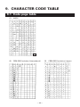
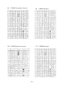
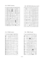
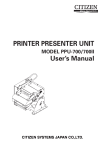
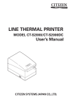
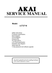
9. CHARACTER CODE TABLE ............................................................... 49
9.1 Code page table ..................................................................................... 49
9.2 International Character Code Table ...................................................... 53
10. EXTERNAL DIMENSIONS ............................................................... 54
—7—
1. INTRODUCTION
The CBM-920II is a dot-impact printer widely usable with various data communication
terminals, POS terminal and measurement terminals.THE CBM-920II, a compact type
printer with rated into a rack.
This printer, being compact and equipped with extensive functions, is suitable to a
wide range of applications.
Read this manual thoroughly to understand the product before use.
1.1 Features
1. Compact desk-top dot matrix printer
2. Light weight
3. Paper-near-end detecting function
4. Autoloading function
5. Conformity to RS-232C and Centronics.
6. 40 digit 24 print digit number digits/type is prepared.
7. Low price
8. Abundant initialization functions with external switch and internal memory switch
9. CBM-920 emulation
10. CBM-920, iDP3110 emulation selectable
1.2 Accessories
Confirm that the printer is supplied together with the following accessories.
Paper roll (1 roll)
Ribbon cassette (1 unit)
I/F cable (1)
Rack Including mounting brackets (1 unit)
Installation metal fittings fixation screw (2)
Wire clamping (1)
User’s manual (1 booklet)
—8—
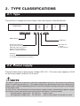
2. TYPE CLASSIFICATIONS
2.1 Type
The product is categorized according to the naming plan indicated below.
CBM-920II
-
24
40
R
P
J
F
-XXX
CBM-920II - 24 R J -XXX
Model Name
OEM spec.
Character set
J: Japan
F: International
Number of columns
24: 24 columns/144 dots
(MD-910 mechanism use)
40: 40 columns/180 dots
(MD-911 mechanism use)
Interface
R: Serial (RS-232C)
P: Parallel (Conformity to Centronics)
2.2 Power supply
Prepare stable power supply having voltage of DC +5V ±5% and current capacity of 2.5A
or more and a peak current of 4 A or more.
NOTE
The power supply of this printer is internally separated in two: one is for control circuit and the
other is for driving mechanism. The supply voltage may be lowered even if the rating of the
power used is sufficient depending on the current consumption during printing or on the length
of the power cord.
In such a case, reconfirming the wiring or power supply used or separating the power supply
for control system and driving mechanism from each other is recommended.
Control power supply (Vcc) DC+5V± 5%
0.2A or more
Driving power supply (Vp)
DC+5V±10% 2.5A or more (Peak current 4A or more)
—9—
2.3 Specifications
1
Item
Printing method
CBM-920II-24**
Dot matrix
2
Printing direction
One-way printing (normal character, inverted character)
3
Character configuration (W × H) (5 + 1) × 8
(4 + 0.5) × 8
4
Character size (W × H)
1.08 × 2.4 mm
5
Number of columns per line
24 columns: 144 dots/line
40 columns: 180 dots/line
6
Printing speed
Approx. 2.5 lines/sec.
Approx. 1.8 lines/sec.
7
Character spacing
1.98 mm
1.19 mm
8
Line pitch
3.52 mm
1.62 × 2.4 mm
CBM-920II-40**
9
Paper feed speed
Approx. 5 lines/s
10
Paper
Single sheet (Thickness: 0.09 mm or less)
Paper roll: 57.5 ±0.5 (W) × φ50 mm
Core ID: φ12 ±1 mm Core OD: φ18 ±1 mm
Approx. 3.6 lines/s
11
Interface
Serial Interface (RS-232C) or Parallel Interface (Conformity to
Centronics)
12
Input buffer
2k bytes/72 bytes (Selectable by memory SW)
13
Emulation
CBM-920 emulation and IDP3110 emulation
(selectable with memory SW)
14
Code page
CP437, 852, 857, 858, 860, 863,865, 866, 869, WPC1252,
Katakana, CBM-920 emulation (Japan, International), Blank page
15
International character
Character of 14 countries is available.
16
Special mode
Hexadecimal dump printing, Memory SW setting
17
Paper-near-end detection
Detected when printing paper gets scarce.
18
Paper-end detection
Printing suspended when printing paper is lost.
19
Autoloading function
Feeds paper by a specified amount when printing paper is set.
20
Error detection
Mechanical lock error, Memory check error, Low voltage/High
voltage error
21
Ink ribbon
Black (Dedicated ribbon cassette)
Service life: Approx. 200,000 letters
22
Voltage
Control system: DC5V ±5% (0.2A)
Driving system: DC5V ±10% (Approx. 2.5A, Approx. 4A peak)
* The user is requested to prepare external power supply.
23
Power consumption
Printing: Approx. 7 VA (Duty: 12%)
Stand-by: Approx. 0.5 VA
24
Weight
Approx. 500 g (Including mounting brackets, ribbon cassette)
25
Reliability
MCBF: Approx. 1.5 million lines MCBF: Approx. 1 million lines
26
Dimension
115 (W) × 65 (H) × 119( D) mm
27
Panel installation hole size
109 (W) × 62 (H) +0 mm, -0.5mm
28
Operating temperature and
humidity
0 to 40°C, 35 to 85% RH (without condensation)
29
Storage temperature and
humidity
–20 to 60°C, 10 to 90% RH (without condensation)
30
Safety standard
UL (RU), TUV-TUV, CE-Marking
VCCI Class A, FCC Class A
— 10 —
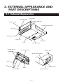
3. EXTERNAL APPEARANCE AND
PART DESCRIPTIONS
3.1 External Appearance
(2) FEED switch
Front cover
Paper cutting part
(3) Paper lamp
(12) Mounting bracket
(4) Knob
ER
PAP
FEE
D
(5) Ribbon cover
Fixed axis
Rear cover
Case
(1) I/F connector
(8) PNE sensor
(6) Paper holder
Ratings seal
(9) DIP switch (SW1)
(11) POWER lamp
Roller
(7) PE sensor
(10) Back switch
— 11 —
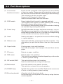
3.2 Part Descriptions
(1) I/F connector
(Interface connector)
Printer can be connected to the signal line of various kinds
of host via a cable. Please ensure that both the printer and
the host are turned off before connecting or disconnecting.
This connector also has a power input.
Connect the FG terminal to the earth.
Cable connected differs with the interface.
(2) FEED switch
Paper is fed while this switch is pressed and held.
Turning the printer power on while pressing and holding
this switch causes self-printing to start.
In the memory switch setting mode, various kinds of setting
are available by pressing this switch.
(3) Power lamp
Lights/blinks when the paper has become scarce or run out.
The lighting status depends on the memory switch setting.
Blinks when mechanism error or the like occurs depending
on the condition of memory switch setting.
(4) Knob
Used to set paper or to open the front cover when setting
or replacing paper.
(5) Ribbon cover
Opened/closed when replacing the ink ribbon cassette. Can
open when you pull the left side of the front face toward
you.
(6) Paper holder
Printing paper is set and fixed here.
Insert the print paper into the paper inlet and then set the
paper.
(7) PE sensor
Detects no paper condition.
(8) PNE sensor
Detects paper-low condition.
This function is enabled or disabled depending on the mode
or memory switch setting.
(9) DIP switch (SW1)
This switch allows basic initial setting.
Use this switch before turning on the printer.
(10) Back switch
Press this switch to use special function.
This switch is not used in normal operation.
(11) POWER lamp
Lighted when power is turned ON. Blinks at the occurrence
of error or during memory switch setting.
(12) Mounting bracket
A bracket to hold the printer body.
Hold the printer to the panel or the like by using the two
screws supplied.
— 12 —
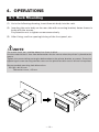
4. OPERATIONS
4.1 Rack Mounting
(1) As in the following drawing, insert themain body into the rack.
(2) Inserting the main body on the rear side with mounting bracket, fasten thema in
body with the screws.
Pay attention not to tighten screws excessively.
(3) After fixing, confirm opening/closing of the front panel, etc..
NOTE
The mount (rack, etc.) shall be about 1 to 3 mm in thick.
Use the material that is free from deformation for the mount when the printer is placed to the
mount.
Tighten the screws taking not to give deformation to the printer, bracket, or mount. Excessive
tightening of screw not only provides stress on the printer but also causes failure in the printer.
Recommended mounting hole dimensions
109 (W) x 62 (H) mm
Tolerance:+0 mm, -0.5 mm
— 13 —
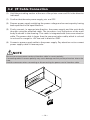
4.2 I/F Cable Connection
(1) Hold the protruding section at the rear of the printer cover and lift in the direction
indicated.
(1) Confirm that themain power supply, etc. are OFF.
(2) Prepare power supply satisfying the power voltage and current capacity having
been specified in the specifications.
(3) Firmly connect, in appropriate direction, the power supply and the main body
through using the attached cable. The connector is at the bottom of the main
body as shown in the drawing. This cable is integrated with the communication
cable. The power cable is larger than the communication cable, which is colored
in red and in orange for +5V use and in black for GND.
(4) Connect a power supply cable to the power supply. Pay attention not to connect
power supply cable in reverse polar.
NOTE
Be sure to connect power cord and interface cable in correct polarity.
Connecting cable in reverse polarity may cause damage not only to the printer but also to the
host.
Hold the connector when connecting or disconnecting the power cord of interface cable.
PAPE
R
FEED
1
2
19
20
— 14 —
4.3 Panel Opening/Closing
4.3.1 Opening/Closing of Front Panel
(1)
Applying your finger on the projection on the left side of the front panel,
pull it forward when the lock is released. It opens by about 180° centering
around the fixed axis.
(2)
For closing, pressing the front panel, tightly close it until click sound is heard.
Also, confirm, on closing, that paper is free of slackening.
4.3.2 Opening/Closing of Ribbon Cover
(1)
When paper is out of the front cover, cut it off.
(2)
Applying your finger on the dent on the left side of the ribbon cover, pull it
forward.
It opens by about 180° centering around the fixed axis.
(3)
For closing, pressing the ribbon cover, close it tightly.
NOTE
When closing the front cover, be sure not to catch paper. Otherwise, printing fault or printer
malfunction may occur.
Front cover
ER
PAP
D
FE E
Ribbon cover
Knob
— 15 —
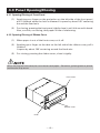
4.4 Paper Feeding
With the FEED switch pressed once, paper is fed by one line.
Paper is fed while it is continuously pressed.
To feed paper, do not pull it forcibly. Use the FEED switch.
During pressing the FEED switch, the data can not be received.
Printing does not start while the switch is pressed. Pressing this switch during printing
does not feed paper.
NOTE
Do not use a pointed object, such as a pen, to press the FEED switch.
Never apply excessive force to the FEED switch.
4.5 Setting Ribbon Cassette
(1) Open the ribbon cover. Be sure to turn off power before opening it.
(3) Confirming the correct direction of a
new ribbon cassette, insert ribbon
between the printing head and the
platen and press cassette down from
the knob side.
PAPER
FEED
PULL
(2) In case the paper is out from front
cover, cut the paper or remove this
paper.
(4) Turning the ribbon cassette knob in the
arrowed direction, remove slack.
(5) On replacing a ribbon cassette, pull it out as holding the "PULL" part.
NOTE
• Leaving the printer for a long time with a ribbon cassette loaded may cause smudged printing.
Continuous printing at low temperature may cause thin printing due to the characteristic of
ink.
• Do not print without ribbon cassette loaded. Otherwise, print head may be damaged.
• Replace the ink ribbon before it is broken by overuse. Do not refill the ink ribbon.
• When setting or removing the ribbon cassette, do not apply excessive force to the ribbon
cassette or printer. Otherwise, printer malfunction may occur.
• Use the specified ink ribbon.
— 16 —
4.6 Setting Paper
(1) Open the front panel.
(2) Use the paper with its end cut straight at right angle or obliquely as shown in the
figure.
(3) Set the roll paper while turning the paper holder in the arrow direction and putting
paper roll core onto the holder.
(4) Insert the end of print paper into the paper insertion slot of the printer.
When auto loading function is enabled, paper is loaded automatically.
When auto loading function is disabled, insert the paper into the insertion slot
while pressing and holding the FEED button. Keep the FEED switch held until
paper appears from the paper exit.
(5) Eliminating slack on the printing paper, close the front panel. Be sure not to
catch paper.
(6) When replacing printing paper, remove the core with the paper holder turned in
the arrow direction. Press the FEED switch to remove the paper remained. Do
not pull the paper forcibly when removing paper.
(7) When setting print paper is completed, press the FEED switch once. The printer
returns to data ready and print ready state.
Note that if “Auto clear after paper setting”is set, completing paper setting
operation automatically enters the data ready and print ready state.
OK
OK
NG
— 17 —
NG
NG
NOTE
• Set the print paper in the correct direction.
• When closing the front panel, be sure not to catch paper. Otherwise, paper jam, etc. may
occur.
• Do not start printing without print paper properly held in the paper holder; otherwise, paper
jam or the like may occur.
• While replacing the paper, do not send data from the host.
• Do not pull the paper in reverse direction of paper feed. This may cause abnormality of print
head.
• In case the paper is set at as skew angle, paper jam may occur. If paper jam occurs, turn off the
power switch and pull out the jammed paper slowly straightforward in the paper feed direction.
• Note that if “Auto clear after paper setting”is set and data is present in the print buffer, print
operation starts automatically after print paper is set.
• Do not use roll paper of φ50 mm or more. Otherwise, paper jam or the like may occur.
NOTES ON PAPER
Shape:
Use the roll paper with the beginning of winding (innermost end of the paper roll)
treated as follows:
(1)
No fold and well aligned to inside diameter.
(2)
No flap
(3)
Not pasted to the paper core (if any).
(4)
No colored part facing PNE sensor (Otherwise, variations in PNE sensor
detection may occur.)
Recommended paper:
One-ply paper..... 45 to 55kg / 1,000 sheets / 1091 x 788 mm
Paper roll diameter
(1)
With core
Use paper core of f12 mm inner diameter and f18 mm outer diameter.
Using paper core of greater than f18 mm or cone type may have effect on
the PNE sensor.
(2)
Without core
Start winding for printing at the position of f12 mm or more. The PNE
sensor starts detection of PNE (Paper Near End) around f20 mm. If you use
a roll paper without core, keep the paper remainder in mind.
If the start of winding is f12 mm or more, print paper may flip flop in the
printer and may affect PNE sensor detection.
— 18 —
4.7 Auto Loading Function
This printer is equipped with a function to automatically load paper.
When print paper is inserted into the insertion slot in accordance with “Setting Printing
Paper” causes paper to be fed automatically by a specified amount.
If print paper is skewed or fed abnormally, remove it gently and insert the paper again.
If you do not want to use this function, set this function disabled by using a memory
switch. (Paper insertion is available with the FEED switch.)
If “Auto clear after paper setting” is set, the printer enters the data ready and print
ready state after completing paper setting. Note that printing starts automatically if
print data is present in the receiving buffer.
If “Clear with FEED switch after paper setting” is set, press the FEED switch once after
completing auto loading.
If paper removal is attempted or paper is not inserted correctly during auto loading,
paper feed operation stops. Insert the print paper again.
NOTE
• Do not pull the print paper during auto loading.
• If print paper is not fed by auto loading, remove the print paper and then insert it again.
• Note the direction of the print paper setting.
— 19 —
4.8 Self-printing Function, Hexadecimal Printing Function
Turning the printer power on while pressing and holding the FEED switch causes the
following state.
Before operating the FEED switch, confirm that the DIP switch (SW1) No. 4 at the back
of the printer is set to OFF.
• Self-printing function
Prints model name, version, initial setting state, etc.
• Hexadecimal printing function
Prints all data sent from the host in hexadecimal code.
This mode lasts till the printer is turned off.
(1) Self-printing function
Turn the printer power on with the FEED switch pressed and held.
Release the FEED switch in 3 seconds after printer power on, and self-printing
starts. After self-printing, normal printing state is restored.
(2) Hexadecimal printing function
Turn the printer power on with the FEED switch pressed and held for approx. 6
seconds and then release the FEED switch. The printer prints “Hexadecimal
Dump” and then stops.
The printer prints data sent from the host by converting it to hexadecimal code.
If the data received last is less than one line, press the FEED switch to print the
received data. Print data for one line differs depending on the specification
(number of digits).
Example of Self-print:
Example of Hexadecimal print:
— 20 —
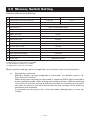
4.9 Memory Switch Setting
<Memory Switch Initial Setting>
NO.
Item
0 International character selection
1
Code page selection
2
Emulation selection
3
Japan (920JPN)
Japanese
International (920Intl)
U.S.A
920 emulation (Japan)
920 emulation (International)
CBM920 emulation
Ack timing *2
After clearing BUSY (After)
Communication error data processing *3
Replace with 7Fh (7Fh)
4
Paper-near-end selection
5
Power ON state
6
Busy signal clear timing *1
CBM-920
7
Input buffer size
2k bytes
8
PE output at PNE *2
Valid
Communication data bit length selection *3
8 bits
9
I/F, LED state at PNE
A
BUSY at FEED switch ON
B
Auto loading
Valid
Online
I/F+LED
Invalid
Valid (short)
C
Clear after auto loading
D
Supply voltage check
Only at power ON
FEED SW
E
Paper lamp
CBM920 emulation
*1: Effective only for parallel I/F (P model).
*2: Applicable to parallel I/F (P model).
*3: Applicable to serial I/F (R model).
Memory switch setting can be changed by a command or by manual operation.
a)
Change by command
Memory switch can be changed by a command. For details, refer to “8.
Print Control Function”.
When the printer receives the command, it outputs a BUSY signal and enters
memory setting mode. After writing into memory switch, software resetting
is carried out and the receive buffer/print buffer are cleared causing each
set value to return to the initial value and then the contents of the memory
switch(es) are reloaded.
Commands are set one by one. Use care when changing two or more set
values.
— 21 —
b)
Change by manual operation
Set the DIP switch (SW1) No. 4 at the back of the printer to ON. Turn the
printer power on while pressing and holding the FEED switch.
The printer prints the information on the current memory switch setting
and then enters the Change Setting mode.
In this case, the PAPER lamp and the POWER lamp blink alternatively at 1second intervals and the BUSY signal is outputted.
Using the FEED switch, choose one of the options for each setting item.
Changing setting item
A total of 15 setting items are available.
The printer prints the contents of setting items and current set values on
print paper.
Pressing the FEED switch short causes the setting item to move.
When all the setting items are changed, the re-setting state or writing
(registering) to memory switch state is reached.
To change the value of setting item, press and hold the FEED switch for
more than 1 second. Current set value is printed with a mark “?”.
Changing options
When item to be selected in the setting items is specified, current option is
printer with a mark “?”.
When selecting an option, press the FEED switch short. Specified options
are printed one by one. When the last option is reached, selection is returned
to the first.
To decide the selection, press and hold the FEED switch for more than 1
second.
Setting options is restored to changing setting items.
Writing the setting items to memory switch (registration)
When the last setting item is selected after setting the options of necessary
setting items, the following is printed.
"Short:Retry Long:Write"
Press the FEED switch for more than 1 second. The printer prints the setting
status and writes the status of setting to the memory switch (registration).
After completion of writing, the printer prints a message and then stops.
After memory switch setting, return the DIP switch No. 4 to OFF.
NOTE
Before turning the printer power on again, return the DIP switch No. 4 to OFF. If the printer is
operated normally with that switch set to ON, the printer prints the message.
When you press the FEED switch for more than 1 second, the PAPER lamp changes from blinking
to lighting condition.
Even when transferring to memory setting mode, the printer detects paper end condition or
the like. However, before transferring to this mode, be sure sufficient paper is present in the
printer.
— 22 —
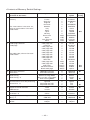
<Contents of Memory Switch Setting>
NO. Setting items
(Printout in the lower)
0 International character selection
country
For international character set,
refer to International Character
Code Table.
1
Code page selection
Codepage
For code page, refer to Character
Code Table.
Options
Value*1
U.S.A
France
Germany
England
Denmark
Sweden
Italy
Spain
Japan
Norway
Denmark 2
Spain
Latin America
Korea
0
1
2
3
4
5
6
7
8
9
10(A)
11(B)
12(C)
13(D)
Printout of
option
USA
FRANCE
GERMANY
U.K.
DENMARK
SWEDEN
ITALY
SPAIN
JAPAN
NORWAY
DENMARK2
SPAIN2
Ltn.Ame
KOREA
Code page 437
katakana
Code page 858
Code page 860
Code page 863
Code page 865
Code page 852
Code page 866
Code page 857
WPC1252
Code page 864
Code page 869
920 Japan
920 International
Blank code page
0
1
2
3
4
5
6
7
8
9
10(A)
11(B)
253(C)
254(D)
255(E)
CP-437
Katakana
CP-858
CP-860
CP-863
CP-865
CP-852
CP-866
CP-857
Windows
CP-864
CP-869
920Jpn
920Intl
Space
CBM920 Emulation
iDP3110 Emulation
0
1
CBM-920
iDP3110
Before clearing BUSY
Before and after clearing BUSY
After clearing BUSY
0
1
2
Before
Center
After
Ignored
Replaced with 3Fh
Replaced with 7Fh
0
1
2
Ignore
3Fh
7Fh
Factory
setting
●*2
●*3
●*3
●*2
●
2
Emulation selection
Emulation
3
ACK Timing
ACK Timing *4
3
Communication error data processing
Comm Error *5
4
Paper-near-end selection
PNE Sensor
Valid
Invalid
0
1
Enable
Disable
●
5
Power ON state
P-ON Sel *6
Online
Offine
0
1
Select
Deselect
●
6
Busy signal clear timing
Busy *7
Standard
CBM-920
0
1
Standard
CBM-920
7
Input buffer size
Buffer
2k bytes
72bytes
0
1
2Kbytes
72bytes
— 23 —
●
●
●
●
NO. Setting items
(Printout in the lower)
8 PE output at PNE
PNE Peout
8
Communication data bit length selection
Bit Length
9
I/F, LED state at PNE
PNE Signal *8
A
BUSY at FEED switch ON
FEED SW Busy
B
Auto loading
AutoLoad
C
Clear after auto loading
AL recover
D
Supply voltage check
Power Check
E
Paper lamp
Paper LED
Options
Value*1
Valid
Invalid
0
1
Printout of
option
Enable
Disable
8 bits
7 bits
0
1
8 bits
7 bits
●
I/F and LED
I/F only
LED only
0
1
2
I/F+LED
I/F only
LED only
●
Invalid
valid
0
1
Disable
Enable
●
Short (Few lines)
Long (Approx 2 times)
Invalid
0
1
2
Short
Long
Disable
●
FEED SW
Auto
0
1
FEED SW
Auto
●
At Power ON
Always
0
1
PowerON
Always
●
CBM-920 Emulation
CBM-920II
0
1
CBM-920
CBM-920II
●
*1:
*2:
*3:
*4:
*5:
*6:
*7:
Value in () is the one printed as the initial setting items in self-printing.
Initial setting value of overseas specification (F model)
Initial setting value of domestic specification (J model)
Setting item of parallel I/F (P model)
Setting item of serial I/F (R model)
In the offline state, pressing the FEED switch once with power ON sets the online state.
Only parallel I/F (P mode) functions
Standard: Clear after confirming the start of STB signal.
CBM-920: Clear after completion of storing data to the input buffer.
*8: Indicates that I/F outputs BUSY at the detection of PNE. LED indicates PAPER lamp.
For the setting of DIP switches, refer to “7. Setting DIP Switches”.
— 24 —
Factory
setting
●
4.10 PNE, PE, Other errors
(1) Paper-near-end (PNE)
When the print paper becomes scarce, the printer detects paper-near-end.
This error occurs when the PNE sensor detects paper-near-end consecutively for
approx. 2 seconds. When the printer detects enough paper for more than 1 second,
the paper-near-end is cleared automatically. The indication and signal status
varies in accordance with the setting status of memory switches 5, 8 and 9.
(2) Paper-end (PE)
If the print paper runs out of paper, the printer detects paper-end. If the printer
detects PE during printing, it stops printing. PE is cleared when new paper is set.
The PAPER lamp lights (blinks) and issues BUSY and PE signals to the host.
(3) Mechanism error (Mechanism alarm)
This alarm is issued when the printer mechanism is locked by paper jam or the
like during printing or paper feeding.
The printer outputs the BUSY and FAULT signals to the host. The PAPER lamp
blinks depending in accordance with the status of memory switch setting.
After removing the error state, press the FEED switch to restore.
If the error state cannot be cleared, turn the printer power off and verify the error
status.
(4) Memory error (RAM error)
This error is issued when error occurs in the memory built in the printer at the
time of printer power on.
The PAPER lamp blinks and outputs BUSY and FAULT to the host.
Turn the printer power off and then turn the printer on. If error still occurs with
the printer power on, this is an unrecoverable error. Contact your nearest CITIZEN
SYSTEMS dealer.
(5) Memory switch error
This error is developed when any abnormality is detected in the setting of memory
switch when the printer is powered on. This error is recovered by resetting the
memory setting and turning the printer power on again.
If the error cannot be recovered even by resetting, turn the printer power off and
contact your nearest CITIZEN SYSTEMS dealer.
(6) Voltage error
This error occurs when the printer detects abnormal supply voltage in mechanism
driving system when the printer power is turned on or during printer operation.
The PAPER lamp blinks and outputs BUSY and FAULT to the host. This is an
unrecoverable error. Turn off the printer immediately.
This error occurs when the fuse for mechanism driving is blown.
For details of the lamp state and interface signal state at the occurrence of error, refer
to the next page.
For serial interface model, read the BUSY signal as DTR signal.
— 25 —
4.11 Clearing Lamp Status, I/F signal status, error, etc.
Lamp status and I/F signal status in various states of the printer are as shown below.
Error state may vary a little depending on the printer mode.
Note that the some indication and output status may vary depending on the setting of
memory switch.
State
Memory switch
Return
RAM error
———
Impossibility
Memory switch error
———
———
Mechanism error
MSW-E:0
FEED switch
MSW-E:1
FEED switch
PNE detection*2
MSW-9:0
PNE clear
Lights
MSW-9:1
PNE clear
MSW-9:2
PE detection
PAPER lamp
POWER lamp
I/F signal line
BUSY, FAULT
Lights
None
Lights
BUSY, FAULT
Lights
BUSY, FAULT
Lights
BUSY, PE *1
Turning off
Lights
PE *1
PNE clear
Lights
Lights
None
Lights
Turning off
MSW-E:0
PE clear
MSW-E:1
PE clear
Lights
BUSY, PE
Lights
BUSY, PE
Voltage error
———
Impossibility
In auto loading
———
———
Lights
Lights
BUSY, PE
PE clear
MSW-C:0
FEED switch
Lights
Lights
BUSY
Pressing FEED switch
MSW-A:0
———
Turning off
Lights
None
MSW-A:1
———
Turning off
Lights
BUSY
At power ON
MSW-5:1
FEED switch
Slow blinking
Lights
BUSY
Hexadecimal dump setting
———
———
Lights
Lights
Memory switch setting
———
———
*Item selection
———
———
BUSY, FAULT
BUSY
BUSY
Lights
*1: Subject to memory switch No.8 setting.
*2: PNE does not function when memory switch No. 4 is disabled.
— 26 —
Lights
BUSY
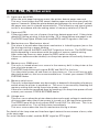
4.12 Special Functions
This printer allows following printing and setting by using “Back switch” located on
the back of the printer.
(1) In case of normal printing operation
When the printer is ready for printing in normal operation, press and hold this
switch for more than 3 seconds (PAPER lamp lights) and then release it. The
printer prints the detailed status of memory switches currently set.
When pressing and holding this switch for more than 6 seconds and then releasing
it (PAPER lamp goes off), the printer starts self-printing.
(2) In case of memory switch setting
When the printer is ready for selecting items in the state of transferring to memory
switch setting mode, pressing and holding this switch for approx. 3 seconds or
more and then releasing it results in transfer to the last item selection state (state
of re-setting or selecting memory switch writing).
If this switch is pressed for approx. 6 seconds or more and then released, the
memory switch is restored to the initial state. As the initial state is only set in the
setting mode, writing to memory switch is necessary. If the FEED switch is kept
pressed when this switch is released, the printer is initialized to domestic setting.
If the FEED switch is not pressed, the printer is initialized to overseas setting.
[Printout of memory switch domestic setting]
— 27 —
5. PARALLEL INTERFACE
5.1 Specifications
(1) Data input system: 8 bit parallel (DATA 1-8).
(2) Control signal: ACK, STB, BUSY, PE, RESET, FAULT
(3) Power cable: +5V, GND and FG
(4) Compatible connector:
HIF3F-20PA-2.54DS(71) (Hirose Electric compatible)
HIF3C-20D-2.54C (Hirose Electric compatible)
5.2 Connector Pin Assignment
Pin
1
STB
Signal Name
Pin
11
2
DATA 1
12
PE
3
DATA 2
13
FAULT
4
DATA 3
14
RESET
5
DATA 4
15
GND (For interface)
6
DATA 5
16
FRAME GND (FG)
7
DATA 6
17
+5V (For circuit control)
8
DATA 7
18
GND (For circuit control)
9
DATA 8
19
+5V (For mechanism drive)
10
ACK
20
GND (For mechanism drive)
19
20
Signal Name
BUSY
1
2
— 28 —
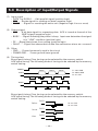
5.3 Description of Input/Output Signals
(1) Input signal
• DATA 1 to DATA 8 . . . 8 bit parallel signal (positive logic)
• STB . . . Strobe signal for reading out data (negative logic)
• RESET . . . Signal for resetting the entire unit (negative logic 4 ms or more)
(2) Output signal
• ACK . . . 8 bit data signal for requesting data. ACK is issued at the end of the
BUSY signal (negative logic)
• BUSY . . . Signal indicating the printer is busy. Input new data when the signal
is in “LOW” condition (positive logic)
• PE . . .Signal that shows form cutting (positive logic)
• FAULT. . . . Signal that shows that trouble like mechanism alarm etc. occurred
(3) Other
• GND . . . Ground commonly used in the circuit
• FRAME GND . . . Frame ground (case ground)
(4) Timing chart
Busy signal timing: Clear timing can be selected by the memory switch.
ACK signal timing: The following kinds of timing can be selected by the memory
switch setting.
POWER
DATA
DATA
DATA
DATA
STB
T2
T1: 2.0us MIN
T2: 500ms MIN
T3: 5us TYP
T1
BUSY
ACK
T3
Busy signal timing: Clear timing can be selected by the memory switch.
ACK signal timing: The following kinds of timing can be selected by the memory
switch setting.
Before
BUSY
ACK
Center
T4
BUSY
ACK
After
BUSY
ACK
T5
— 29 —
T4: 5us TYP
T5: 5us TYP
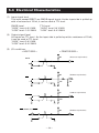
5.4 Electrical Characteristics
(1) Input signal level
The input except RESET are CMOS signal levels. As the input side is pulled up
with a resistance of 10 kΩ, it can be used at TTL level.
CMOS Level
“HIGH” level: 4.0 V MIN
“LOW” level: 1.0 V MAX
TTL Level
“HIGH” level: 2.4 V MIN
“LOW” level: 0.4 V MAX
(2) Output signal level
All inputs are TTL level. As the input side is pulled up with a resistance of 10 kΩ,
it can be used at TTL level.
“HIGH” level: 2.4 V MIN
“LOW” level: 0.4 V MAX
(3) I/O conditions
< HOST SIDE >
< PRINTER SIDE >
DATA
10k
(HC573 or equivalent)
10k
(HC04 or equivalent)
STB
330
102
5k
102
(7406 or equivalent)
RESET
104
ACK, BUSY, PE, FAULT
10k
— 30 —
(HC05 or equivalent)
6. SERIAL INTERFACE
6.1 Specifications
(1) Synchronization: Asynchronous
(2) Baud rate
1200, 2400, 4800, 9600, 19200 Baud/sec (User selection)
(3) Word configuration
• Start bit: 1 bit
• Data bit: 7 bits or 8 bits (User selection)
• Parity bit: odd, even, no parity (User selection)
• Stop bit: 1 bit or more
(4) Data I/O signal
RxD, TxD (RE-232C)
(5) Control signal
DTR, PE, RESET, FAULT
(6) Signal polarity
RS-232C
• Mark = Logic “1” (−3 V to −12V)
• Space = Logic “0” (+3 V to +12 V)
TTL , CMOS
• H level = Logic “1”
• L level = Logic “0”
(7) Power cable
+5V, GND and FG
(8) Compatible connector:
HIF3F-20PA-2.54DS(71) (Hirose Electric compatible)
HIF3C-20D-2.54C (Hirose Electric compatible)
6.2 Connector Pin Assignment
Pin
1 to 8
Signal Name
N.C (Unconnection)
Pin
15
Signal Name
GND (For interface)
FRAME GND (FG)
9
RxD
16
10
TxD
17
+5V (For circuit control)
11
DTR
18
GND (For circuit control)
12
PE
19
+5V (For mechanism drive)
13
FAULT
20
GND (For mechanism drive)
14
RESET
19
20
1
2
— 31 —
6.3 Description of Input/Output Signal
(1) Signal input to printer (RS-232C)
RxD(RECEIVE DATA) . . . Serial receive data signal
(2) Signal input to printer (TTL,CMOS)
RESET. . . Signal for resetting the whole printer (negative logic) 4 ms or more
(3) Signal output from printer (RS-232C)
TxD(TRANSMIT DATA). . .Serial transmit data signal
DTR(DATA TERMINAL READY)
When this signal is Ready (Space), send data or command from the host. If
transmission is made when this signal is Busy (Mark), overrun error occurs.
If the signal is ready even if the printer is in printing operation, data can be
sent to the input buffer.
At the time of printer power on, test printing, reset occurrence, and memory
switch setting, this signal is Busy.
(4) Signal output from printer (TTL,CMOS)
PE. . . Signal indicating end of paper (positive logic)
FAULT. . . Signal indicating occurrence of failure such as mechanism alarm
(negative logic)
(5) Data configuration
One data frame
t
Mark
b0, b1, b2, ...
Space
(1)
(2)
(3)
(4)
(1) Start bit (1 bit)
(2) Data bit (7/8 bits)
(3) Parity bit (0/1 bit)
(4) Stop bit (more than 1 bit)
* Parity bit may or may not be present.
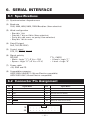
6.4 Electrical Characteristics
(1) RS-232C I/O signals (RxD/TxD/DTR)
• Input (RxD), Output (TxD)
Mark = (−8 V): Stop bit
Space = (+8 V): Start bit
< printer side >
< host side >
RxD
TxD
• Output (DTR)
Mark = (−8 V): For Busy
Space = (+8 V): For Ready
DTR
(MAX232E compatible)
— 32 —
(MAX232E compatible)
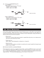
(2) TTL circuit (PE/RESET/FAULT)
Input (RESET)
The input signal level is TTL level.
“HIGH” level: 2.4 V MIN
“LOW” level: 0.4 V MAX
5K
RESET
104
(7406 compatible)
Output (RE/FAULT)
The output signal level is TTL level.
“HIGH” level: 2.4 V MIN
“LOW” level: 0.4 V MAX
10K
PE/FAULT
(HC05 compatible)
6.5 Error Detection
This printer detects the following communication errors in the data communication
of serial interface. When any error occurs, the printer converts (or may ignore in
some case) the data at the occurrence of the error to the characters set by the memory
switch and then prints the characters.
• Parity error
Parity error occurs when parity check is specified and parity is not observed in
the even and odd parity checks.
• Framing error
When space state detected on detection of stop bit.
• Overrun error
This error occurs when next data is transferred to receiving buffer though input
buffer is full of data.
RECEIVING CONTROL AND BUFFERING
This equipment controls, on receipt of print data, receiving (DTR Control) in one-word
unit. If the host disregards DTR and carries out data transmission at this time, overrun of receiving data may be resulted. This state should be avoided on the host’s
responsibility. (The data discharging type host cannot follow this.)
— 33 —
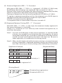
7. DIP SWITCH (SW1) SETTING
7.1 DIP Switch Position
DIP switch (SW1) is located at the back of the printer as shown in the figure below.
The polarity and part of the function of the switch differs depending on the interface.
For memory switch setting, refer to “4.9 Setting Memory Switches”.
NOTE
Before setting, turn the printer power off.
Do not use edged object, such as a pen, to change the switch.
Serial
ON
1 2 3 4 5 6 7 8
Parallel
ON
1 2 3 4
7.2 Parallel Interface Type
Switch No.
1
Function
Character direction
OFF
Normal
ON
Inverted
Factory Setting
OFF
2 (920)*
CR command
Ignore CR
CR + LF
OFF
2 (3110)*
CR command
CR
LF
OFF
3
RESET in
Disable
Enable
ON
4
Memory switch
Disable Setting
Enable Setting
OFF
*: Difference may occur in accordance with the emulation set by the memory switch.
After setting DIP switch No. 4 to ON, turning the printer power on with the SEL switch
pressed and held causes the printer enter the Manual memory switch setting mode.
After manual setting mode, be sure to set this switch to OFF.
— 34 —
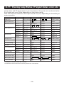
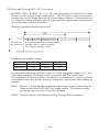
7.3 Serial Interface Type
Switch No.
1
Function
Character direction
OFF
Normal
ON
Inverted
Factory Setting
OFF
2 (920)*
CR command
Ignore CR
CR + LF
OFF
2 (3110)
CR command
—
—
OFF
3
Reset in
Disable
Enable
ON
4
Memory switch
Disable Setting
Enable Setting
OFF
5
OFF
Transmission rate
and parity
6
7
The following reference
OFF
OFF
8
OFF
* Difference may occur in accordance with the emulation set by the memory switch.
Set DIP switch No. 4 to ON. Then turn the printer power on while pressing and holding
the FEED switch. The printer enters the manual memory switch setting mode. After
manual setting mode, be sure to set this switch to Off.
Baud rate and parity selection
Baud Rate
(bps)
Parity
4800
None
O
1200
None
—
2400
None
—
4800
None
—
9600
None
—
ON
19200
None
—
OFF
1200
Odd
—
ON
2400
Odd
—
OFF
4800
Odd
—
ON
9600
Odd
—
OFF
19200
Odd
—
ON
1200
Even
—
OFF
OFF
2400
Even
—
ON
OFF
ON
4800
Even
—
ON
ON
ON
OFF
9600
Even
—
ON
ON
ON
ON
19200
Even
—
8
OFF
Switch No.
7
6
OFF
OFF
5
OFF
OFF
OFF
OFF
ON
OFF
OFF
ON
OFF
OFF
OFF
ON
ON
OFF
ON
OFF
OFF
OFF
ON
OFF
OFF
ON
ON
OFF
ON
ON
ON
OFF
OFF
ON
OFF
OFF
ON
OFF
ON
ON
OFF
ON
ON
ON
ON
— 35 —
Factory Setting
8. PRINT CONTROL FUNCTION
8.1 List of Control Codes
Emulation
CBM920 iDP3110
O*1
O*1
LF
Code
Function
(Hexadecimal)
0A
Line feed after print
CR
0D
Carriage return and line feed
O*1
O*1
1
SI
0F
Normal size character
O
O
2
2
Symbol
No.
1
SO
0E
Double width character
O
O
RS
1E
Double width character
O
—
2
US
1F
Normal size character
O
—
2
CAN
18
Cancel data
O
—
3
DC2
12
Inverted character
O
—
4
DC1
11
Initialize
O
—
5
ESC + “B”
1B, 42
Feed paper continuously
O
O
6
7
ESC + “R”
1B, 52
Select international character
O
O
ESC + “t”
1B, 74
Select code page
O
O
8
ESC + “/”
1B, 2F
Register sentence
O
—
9
ESC + “! ”
1B, 21
Print registered characters
O
—
10
ESC + “%”
1B, 25
Enable/Disable registered characters
O*2
O*2
11
ESC + “&”
1B, 26
Register user-defined character
O*3
O*3
12
ESC + “K”
1B, 4B
Print bit image
O
O
13
FS + “W”
1C, 57, 1
Double height and width character / clear
O
—
14
ESC + “A”
1B, 41
Set line spacing
—
O
15
DC4
14
Clear double width character
—
O
DC3
13
Power down function
O*4
O*4
16
DC2
12
Power down function
—
O
16
ESC + “) ”
1B, 29,
Change memory switch
O
O
17
*1: Invalid in some case. Refer to the descriptions for “LF” and “CR”
*2: Invalid in some case. Refer to the descriptions for “Enable/Disable registered characters”.
*3: Function differs by the number of printable columns (specification). Refer to the descriptions for
“Register user-defined character”.
*4: Different in function. Refer to the descriptions for “Power down function”.
— 36 —
2
8.2 Control Code Details
(1) Command for Line Feed After Printing (CR/LF)
By entering CR (0DH)/LF (0AH) codes, data in the print buffer is printed followed
by a line feed. Without data in the print buffer, only a line feed is performed.
This command is ignored just after buffer full in case of 920 emulation.
CR and LF are valid in the following conditions.
Serial
SW1 Switch No.1
OFF
ON
LF only
CR and LF
Parallel
LF only
Serial
SW2 Switch No.2
OFF
ON
CR only
LF only
Parallel
LF only
CBM-920 Emulation
iDP3110 Emulation
CR and LF
CR only
(2) Specify/Clear double-width character (SI, SO, US, RS, and DC4) command
SI/SO codes function in the same manner as US/RS as long as 8-bit data are
assigned (serial communication data bit length), which, however, are divided,
under 7-bit assignment, into SI (20H~7FH characters) print assignment and SO
(A0H~FFH characters) print assignment functions.
1.
Standard letter assignment (SO/RS) command:
With SI (0FH)/US (1FH) codes input, lateral enlargement is cancelled and
the data following are printed in standard letters. This command can cancel
only lateral enlargement, which dose not apply to ×4 enlargement.
2.
Laterally enlarged letter assignment (SO/RS) command:
With SO (0EH)/RS (1EH) codes input in any columns, the data following are
printed in prints enlarged double in width.
Although standard and enlarged letters can be mixed within one line,
automatic (buffer-full) printing takes place when the number of columns
reaches 24 (or 40) counted in standard letters. With 920 emulation, laterally
enlarged letter assignment is cleared by printing after line feed, followed
by SI, US, and DC1. With 3110 emulation, it is cleared by printing after line
feed by LF and CR, followed by SI, US, and DC4.
[Example of receive data
(For 24-column model)]
[Results of Printing]
SO
1234567890
SO
123
SI
SO
123
SI ABCD SO
SO
SO
12345678901B
CR
ABCD
CR
12
CR
— 37 —
(3) Data Cancel (CAN) Command
With CAN (18H) code input, print data held within the line before input of the
CAN code are all cancelled.
[Example of print data]
SO
123456
CAN
[Results of Printing]
ABC
CR
ABC
* As data “123456” are cancelled without the command “SO” cancelled, “ABC”
is printed in lateral enlargement.
(4) Inverted Letter Assignment (DC2) Command
When data are input with DC2 (12H) attached at the beginning of a line (invalid
when attached to any other place), data following are all printed in inverted letters.
To cancel this, input either DC2 again or DC1 (initial setting.)
(5) Initial Setting (DC1) Command
With DC1 (11H) input, various conditions set after power supply are cancelled
and the state as at supply of power is restored.
Content of the input buffer, however, is held unchanged.
(6) Continuous Paper Feed Assignment (ESC + “B”) Command
With ESC (1BH) +“B” (42H) + n code input, continuous paper feed at n-dot line is
executed.
However, n allows continuous paper feed to be executed at even-numbered dot
line in the range of 4 ≤ n ≤ 255. If n is specified otherwise, this command is
cancelled.
When this command is entered, print data, if any, in the input buffer is printed.
Print line (10-dot line) is included in the amount of line feed “n”; therefore, 4 ≤ n
≤ 9 provides a line space of “0”.
— 38 —
(7) International Character Select (ESC + “R”) Command
By entering the code ESC (1BH) + “R” (52H) + n, characters input hereafter are set
to the characters for the following countries.
With n other than those specified, the set value for the U.S. is assigned.
n
0
Country
U.S.A. (USA)
n
5
Country
Sweden (SWE)
n
10
Country
Denmark 2 (DEM 2)
1
France (FRA)
6
Italy (ITA)
11
Spain 2 (SPN 2)
2
Germany (GER)
7
Spain (SPA)
12
Latin America ( )
3
U.K. (U.K)
8
Japan (JPN)
13
Korea (KOR)
4
Denmark (DEM)
9
Norway (NOR)
Note : International character set at printer power on and after reset signal input
differs depending on the status of memory switch setting.
(8) Codepage Select (ESC + “t”) Command
By the entry of ESC (1BH) + ”t” (74H) + n code, the follwing character code table
can be selected. When n is other than specified, it is set to code page CP437.
n
0
Character Code Table
CP437 (USA,Std-Europe)
n
8
Character Code Table
CP857 (Turkish)
1
2
Katakana
9
WPC1252 (Win. Latin1)
CP858 (Multilingual)
10
CP864 (Arabic)
3
CP860 (Portuguese)
11
CP869 (Greek)
4
CP863 (Canadian-French)
5
CP865 (Nordic)
253
CBM-920 Emulation (Japan)
6
CP852 (Eastern Europe)
254
CBM-920 Emulation (International)
7
CP866 (Russian)
255
Blank page
Note : Code page at printer power on and after reset signal input differs depending
on the status of memory switch setting.
Factory setting for “F” model of character set in model category is CBM920 overseas compatible and that for “J” model is CBM-920 domestic
compatible.
— 39 —
(9) Sentence Registration (ESC + “/”) Command
With input of ESC (1BH) + “/” (2FH) + n + ‘registered’ + CR (0DH) / LF (0AH) code,
24 (40)-bytes data following n are registered. Set a numeral of 1~8 to n.
With any other numeral having been set, data following is regarded as print data,
where no registration takes place and printing conducted.
Data cannot exceed one line and must be ended with CR (0DH) or LF (0AH).
To register a statement exceeding one line, the statement up to 24 (40) bytes is
registered and the data following is printed out as print data.
The ESC command cannot be registered.
The registered data is cleared when the printer is turned off.
(10) Registered Sentence Printing (ESC + “!” ) Command
With ESC (1BH) + “!” (21H) + n code input, the statement already registered in
the numeral assigned to n is printed.
Assign, to n, a numeral of 1 to 8. With any other numeral having been set, no
execution takes place.
Note 1: As much as 24 (40) bytes of data can be registered. In case that 24 (40)
columns are exceeded on printing (because of enlarged or ×4 letters
having been assigned, etc.), printing is conducted up to 24 (40)th column
and the columns overflowed are printed in the next line. Be sure to
make registration in consideration of printing results.
Note 2: When double height and width character printing or inverted character
printing is executed in registered sentence printing, this setting is active
even after returning to normal printing unless that setting is cancelled.
[Application Example]
[Registered State]
ESC
/
1 This is a pen CR
Registered in 1.
ESC
/
9 It this a pen ? CR
No registration made with 9.
ESC
/
1 Is this a pen CR
Overwritten on sentence registered initially in 1.
ESC
!
1
1
2
3
4
5
6
7
8
It is a pen
Printing of sentence registered in 1.
[Printing Result]
(Printed without registration)
(Printed with ESC+!+1)
— 40 —
(11) Registered Letter Valid/Invalid (ESC + “%”) Command
Whether a registered pattern is valid or invalid is set with ESC (1BH) + ”%” (25H)
+ n code being input.
n = 1 (01H):
Registered pattern to be made valid.
(Addresses for which no registration change has been conducted are taken as
inside fixed characters.)
n = 0 (00H):
Registered pattern to be made invalid.
(Taken as inside fixed character sets.)
With CBM-920 emulation 40-digit version, to use the registered characters, it is
necessary to set the registered characters to be valid using this command. With
iDP3110 emulation and CBM-920 emulation 24-digit version, the registered
characters are valid at the registration of the user-defined characters without
setting the registered characters to be valid.
To reset to the state where inside fixed characters are usable while registered
characters are valid, it is necessary to disable the registered characters. Command
for setting to invalid operates regardless of the emulation or number of digits.
Registered Characters Enable/Disable Command
CBM-920 Emulation (40 digits)
Set to Valid
O
Set to Invalid
O
CBM-920 Emulation (24 digits)
×
O
iDP3110 Emulation (40 digits)
×
O
iDP3110 Emulation (24 digits)
×
O
O: Operation enabled by the Valid/Invalid command of registered characters.
×: As the registered characters are valid by the Register User-defined Character
command, it is not necessary to set the registered characters to be valid.
(12) Character Registration (ESC + “&”) Command
1.
For 24-column model (ESC + “&” + A1 + A2)
Individual patterns can be registered by entering the code ESC (1BH) + ”&”
(26H) + A1 + A2, then entering the pattern data.
A maximum of 224 characters can be registered, and any address in the
range of 20H to FFH can be used for the registration. However, if a new
pattern is registered in an address already in use, existing data is cleared
and the newly entered data becomes valid.
[Address setting]
Specified address is matched to the character code and can be accessed
likewise to the stored fixed character record. If a fixed character is defined
in the specified address, the fixed character becomes invalid.
A1 signifies the starting address for the registrations, A2 is the ending
address. When A1<A2 or (A2-A1)>7 is specified, no registration occurs and
data following is treated as print data.
— 41 —
[Method of data transmission]
1)
Single character registration
Select the address to be defined (character code) from among 20H to
FFH and designate is as A1. When registering a single character,
starting and ending addresses match each other. That is, A1=A2.
<Example>
A 6 × 6 dot matrix full dot pattern is to be registered in address 41H
(code for the fixed character “A”. (Numerals are hexadecimal.)
ESC + “&” + A1 + A2 + “Pattern data (6 bytes)”
1B
36
41 41
FF FF FF FF FF FF
In the successive controls, a 6 × 8 dot matrix full dot is output whenever the
character code 41H is specified. (Character “A” cannot be accessed.)
2)
Multiple character registration
By repeating the single character registration, a maximum of 8
characters can be registered. When defining multiple characters in a
successive address (character code), register pattern data for a
maximum of 8 characters by designation A1 as the starting address
and A2 as the ending address.
((A1-A2)+1)x6 bytes are required for pattern data.
Note: A1 < A2, A2 – A1 ≤ 7
[Pattern data configuration]
Pattern data to be registered must consist of 6 bytes per character. That is,
pattern data configured by a 6 × 8 dot matrix is broken up into 6 vertically
positioned units each of which is represented by 1 byte of data. All together,
6 bytes of data are transmitted.
<Example> When transmitting the following data:
1
2
3
4
5
6
1
2
3
4
5
6
0
1
2
3
4
5
6
7
[Printing of registered letters]
To print registered character, in the same manner as printing other fixed
characters, use the commands (CR, LF, ESC + B + n).
— 42 —
2.
For 40-column model
In CBM-920 emulation (ESC + “&” + C1 + A1 + A2)
In iDP3110 emulation (ESC + “&” + A1 + A2)
With ESC (1BH) + ”&” (26H) + {C1} + A1 + A2 code and the pattern data
following input, a pattern is registered. Only CBM-920 emulation is specified
for { }. Up to 224 characters can be registered into addresses from 20H to
FFH. When the same pattern data is registered in the same address, data
registered before is cleared and the new data becomes valid.
[Recognition of use of upper most bit]
For recognition of use or non-use of the uppermost bit by a character to be
registered, set data to Parameter C1.
C1=0 (00H): Uppermost bit not used.
Other than C1=0: Uppermost bit used.
If 0 is set to this parameter regardless of whether most significant bit is
specified, character as imaged cannot be registered.
[Setting of addresses]
A1 : Registration starting address (20H~FFH)
A2 : Registration ending address (20H~FFH)
[Pattern data configuration]
Pattern data to be registered must consist of 9 bytes per character. That is,
pattern data configured by 9 × 8 dot matrix is broken up into 9 vertically
each of which is represented by 1 byte of data. All together, 9 bytes of data
are transmitted.
In case of iDP3110 emulation, blank data is automatically assigned to the
8th and 9th lines and pattern data consisting of 7 bytes is transferred.
<Example> When transmitting the following pattern data:
In CBM-920 emulation
1
2
3
4
5
6
7
8
9
1
0
2
3
*
4
5
*
6
7
8
*
*
*
*
9
*
1
2
*
3
*
*
4
5
*
6
*
*
7
41H 22H 55H 08H 41H 00H 41H 00H 00H
— 43 —
In iDP3110 emulation
1
2
3
4
5
6
7
1
2
0
3
4
*
5
6
*
1
7
*
*
2
*
*
3
*
4
*
5
6
*
*
*
7
41H 22H 55H 08H 41H 00H 41H
As the 40-column model is of half-dot printing system, continuous dots
cannot be arranged in the printing direction (lateral direction). Therefore,
even if any pattern is specified at point “*” at the right of point “●” above,
it cannot be registered as a pattern.
In case of CBM-920 emulation, when data is printed with print data arranged
on the 9th line, some effect may occur in the print pattern of the next print
character.
In case of CBM-920 emulation, registering two-character data and configuring
one double-width character is available.
<Example> When registering a Japanese character “ ” by using two
characters 41H and 42H
1
2
3
4
5
6
7
8
9
41H
1
2
3
4
5
6
7
8
9
42H
Following ESC + & + 01 (Note) + 41H + 42H
sending data 80H, 00H, 81H, 00H, 89H, 00H, 89H, 00H, FFH
00H, 89H, 00H, A9H, 40H, 81H, 00H, 80H, 00H
allows “ ” to be registered at 41H and 42H.
[Printing registered character]
To print a registered character, executing Activate Registered Character
command may be required in some case. If you want to return to the internal
characters, it is necessary to disable the registered characters.
— 44 —
(13) Bit Image Printing (ESC +“K”) Command
With ESC (1BH) + K (4BH) + n1 + n2 + n3 code being input, conversion from Text
mode into Bit Image mode takes place. The n1/n2/n3 assigns amount of
transmission of bit image data which follows these. Where, n1 represents the
no. of bytes in lateral direction and n2 (lowermost)/n3 (uppermost) represent the
no. of dot lines in vertical direction.
[Relations between data and print-out]
n1
1 byte
D8
n3 × 256 + n2
No. of dot lines
D7
D6
D5
D4
D3
D2
D1
D1~D8 indicate dot location in each position.
To place a dot in a particular position,
put 1 in binary and 0 for a space.
[Parameter assignable range]
Model
24 columns
n1
1~18
n2
0~255
n3
0~1
40 columns
1~23
0~255
0~1
In case that assignment has been made out of the assignable range or n2 = n3 =
0 has been assigned, Bit Image mode is cancelled and Text mode starts.
On completion of receiving 4-dot-line data or on completion of receiving n1/n2/
n3 assigned data, this printer starts printing with insufficient data treated as
spaces.
Note 1: With n1 = 23 having been assigned in 40-column model, 4 dots from the
lowermost column (LSC-DOT) are made invalid. This is because the
printing position in one line equals 180 dots.
Note 2: On termination of bit image printing, Text mode is reinstated.
— 45 —
(14) x4 Enlarged Letter Assignment / Cancel (FS + “W”) Command
Specifies/clears double-height, double-width character by the entry of FS (1CH) +
“W” (57H) + n code. If double-height, double-width character is specified,
character data following this code is printed enlarged by 2 times both vertically
and horizontally.
n= (00H) : Clears double-height, double-width character.
n= (01H) : Specifies double-height, double-width character.
Note 1: Although standard and laterally enlarged letters can coexist in one line,
automatic (buffer-full) printing takes place on reaching to 24th (40th)
column counted in standard characters.
Note 2: With x4 enlargement and double-width having been assigned, x4
enlargement has priority.
[Receiving Data]
[Results of Printing]
FS W 1 123456789 CR
FS W 0 ABC FS W 1 123 CR
FS W 1
A FS W 1 12345678901B
The last letter, although in ×4 assignment, is
printed in standard letter since it being in the
24th column.
(For 40 column model, this applies to the 40th
column.)
(15) Set Line Spacing (ESC + “A”) Command
Sets a line space of “n” dot line by the entry of ESC (1BH) + “A” (41H) + n code.
Initial setting is 2-dot line space.
Here, n is an even number in the range of 0 £ n £ 255.
Note:
When an odd number is set to n, a line space of n-1 dots is specified.
When n=0 or 1 is specified, continuous printing is permitted.
(16) Power Down Function (DC2, DC3) Only when 3110 emulation is selected
1.CBM-920 emulation
When the DC3 (13H) code is entered, the POWER lamp on the back of the
printer goes off.
In other case, normal operating condition is maintained.
If paper-end, mechanism error, or the like occurs, the POWER lamp lights/
blinks correspondingly and returns to normal indication.
The DC2 (12H) code is assigned to the command with another meaning.
— 46 —
2.iDP3110 emulation
In order to reduce power consumption when printer is not in operation, two
power down modes triggered by the codes DC2 (12H) and DC3 (13H) are
available with this printer.
When the printer receives DC2 (12H) or DC3 (13H), it enters the power down
mode after all data previously received is printed out.
To exit the power down mode, re-enter the printer power or apply the “LOW”
signal to the RESET terminal for more than 4 ms.
(a)
DC2 (12H)
The printer enters the power down mode when DC3 (13H) code is
entered. In this mode, the oscillator does not stop oscillation.
(b)
DC3 (13H)
The printer enters the power down mode when DC2 (12H) code is
entered. Operation of the oscillator is terminated, reducing the power
consumption to less than that of the DC2 power down mode.
(17) Change Memory Switch (ESC + “)“) Command
By the entry of the ESC(1BH)+ “)”(29H)+55H+n1+n2+AAH code, contents of
memory switch shown in the table below can be changed.
When receiving this code, the printer enters the BUSY state and writes specified
data (value) to the memory switch.
In this case, the printer performs reset operation. Here, the input buffer/print
buffer is cleared, all set values are restored to the initial value, and the contents
of memory switch are read again.
This command cannot be executed consecutively. When two or more memory
settings are changed, set the value one by one.
NOTE
• If the parameter value is other than specified, writing to memory switch is not carried out.
• If the first byte and the fourth byte of parameter is other than specified code, writing to memory
switch is not carried out.
• In case of serial interface, communication bit length must be set to 8 bits. When set to other
than 8 bits, the communication bit length must be set to 8 bits by manual setting or the like.
* For manual setting, refer to “4.9 Setting Memory Switch”.
— 47 —
Setting range of parameters n1 and n2 is as shown below.
n1
0
Function
Select international character set
1
Select code page.
2
Select emulation
3
4
5
n2
0~13
Content of Setting
See International Character Code Table.
0~11, 253, See Character Code Table Select
254, 255 Command.
0
CBM-920 Emulation
1
iDP3110 Emulation
ACK timing
0
Before clearing BUSY
(When it is a parallel I/F model )
1
Before and after clearing BUSY
2
After clearing BUSY
Communication error data processing
0
Valid
(When it is cereal I/F model. )
1
Replace with 3Fh
2
Replace with 7Fh
0
Valid
1
Invalid
Paper-near-end (PNE) function
0
Online
1
Offline
Busy signal clear timing
0
Standard
(The function is not provided in cereal I/F model. )
1
CBM-920 Emulation
7
Input buffer Size
0
2k bytes
1
72 bytes
8
PE output at PNE
0
Valid
6
Power ON state
(When it is a parallel I/F model )
1
Inalid
Communication data bit length selection
0
8 bits
(When it is cereal I/F model. )
1
7 bits
I/F, LED state at PNE
0
I/F+LED
(I/F shows the BUSY signal and
1
I/F only
LED shows the Paper lamp. )
2
LED only
10
BUSY at FEED switch ON
0
Valid
(When it is a parallel I/F model )
1
Inalid
11
Auto loading
0
Short
(When it is a parallel I/F model )
1
Long (Approx 2 times)
9
2
Invalid
FEED SW
12
Clear after auto loading
0
1
Auto
13
Supply voltage check
0
At Power ON
1
Always
14
Paper lamp
0
CBM-920 Emulation
1
CBM-920II
— 48 —
9. CHARACTER CODE TABLE
9.1 Code page table
(1)
ASCII
(2)
CBM-920 Emulation (International)
— 49 —
(3)
CBM-920 Emulation (Japan)
(4)
CP437 (USA, Std-Europe)
(5)
Katakana
(6)
CP858 (Multilingual)
(7)
CP860 (Portuguese)
— 50 —
(8)
CP863 (Canadian-French)
(9)
(10) CP852(Eastern Europe)
CP865 (Nordic)
(11) CP866(Russian)
— 51 —
(12) CP857 (Turkish)
(13) WPC1252 (Windows Latin1)
(14) CP864 (Arabic)
(15) CP869 (Greek)
— 52 —
9.2 International Character Code Table
Country
U.S.A
France
Germany
U.K.
Denmark I
Sweden
Italy
Spain I
Japan
Norway
Denmark II
Spain II
Latin
Korea
— 53 —
10. EXTERNAL DIMENSIONS
— 54 —
1.01E-0612 Printed in Japan