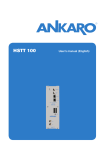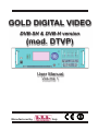
1
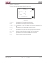
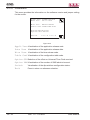
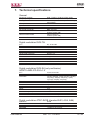
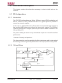
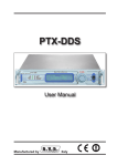
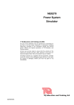
GOLD DIGITAL VIDEO
DVB-SH & DVB-H version
(mod. DTVP)
User Manual
Volume 1
Manufactured by
Italy
File Name:
03_GOLD DIGITAL VIDEO_DTVP_DVBSH&H_ING_1.0.indd
Version:
1.0
Date:
11/06/2008
Revision History
Document History
Date
Version
11/06/2008 1.0
Reason
First Edition
Editor
E. Montagna
DTVP - User Manual
Version 1.0
© Copyright 2008
R.V.R. Television
Via del Fonditore 2/2c - 40138 - Bologna (Italia)
Telephone: +39 051 6010506
Fax:
+39 051 6011104
Email:
[email protected]
Web:
www.rvr.it
All rights reserved
Printed and bound in Italy. No part of this manual may be reproduced,
memorized or transmitted in any form or by any means, electronic
or mechanic, including photocopying, recording or by any information storage and retrieval system, without written permission of the
copyright owner.
DTVP
Table of Contents
1.
2.
3.
3.1
3.2
4.
4.1
5.
5.1
5.2
6.
6.1
6.2
7.
8.
8.1
8.2
8.3
8.4
8.5
8.6
8.7
9.
9.1
9.2
9.3
10.
10.1
10.2
10.3
11.
11.1
11.2
11.3
12.
Preliminary Instructions
Warranty
First Aid
Treatment of electrical shocks
Treatment of electrical Burns
Unpacking
General Description
Quick guide for installation and use
Preparation
First power-on and setup
Operating System
Using the encoder
DVB-SH & H Software
Technical Specifications
Functional Description
RF Configurations
Electrical power section
Cooling system
Power Supply
CPU
Modulator
Interface Card
External description
Front panel
Rear panel
Connectors
System Status Enquiries
Remote alarm monitoring
Remote enquiries using remote control software (Opt.)
Remote control (Opt.)
Remote Alarm Reporting and Control (Opt.)
Preparation
Remote alarm reporting confi guration
Remote control
Remote Alarm Reporting and Control (Opt.)
User Manual
Rev. 1.0 - 11/06/08
1
1
2
2
2
3
4
5
5
6
9
9
10
33
35
35
37
37
37
37
38
38
41
41
42
43
44
44
44
44
46
46
47
51
52
i
DTVP
This page was intentionally left blank
ii
Rev. 1.0 - 11/06/08
User Manual
DTVP
IMPORTANT
The lightning flash with arrowhead, within a triangle, is intended to alert the user of the presence
of dangerous voltage that may constitute a risk of electric shock.
The exclamation point within an equilateral triangle is intended to alert the user to the
presence of important operating and maintenance (servicing) instructions in the literature
accompanying the equipment.
1.
Preliminary Instructions
• General Warnings
This equipment should only be operated, installed and
maintained by “trained” or “qualified” personnel who are familiar
with risks involved in working on electric and electronic circuits.
“Trained” means personnel who have technical knowledge of
equipment operation and who are responsible for their own
safety and that of other unqualified personnel placed under
their supervision when working on the equipment.
“Qualified” means personnel who are trained in and
experienced with equipment operation and who are
responsible for their own safety and that of other unqualified
personnel placed under their supervision when working on
the equipment.
WARNING: Residual voltage may be present inside
the equipment even when the ON/OFF switch is set to
Off. Before servicing the equipment, disconnect the
power cord or switch off the main power panel and
make sure the safety earth connection is connected.
Some service situations may require inspecting the
equipment with live circuits. Only trained and qualified
personnel may work on the equipment live and shall be
assisted by a trained person who shall keep ready to
disconnect power supply at need.
R.V.R. Television shall not be liable for injury to persons or
damage to property resulting from improper use or operation
by trained/untrained and qualified/unqualified persons.
WARNING: The equipment is not water resistant.
Any water entering the enclosure might impair proper
operation. To prevent the risk of electrical shock or
fire, do not expose this equipment to rain, dripping or
moisture.
Please observe local codes and fire prevention rules when
installing and operating this equipment.
Operation of this equipment in a residential area may cause
radio interference, in which case the user may be required
to take adequate measures.
The specifications and data contained herein are provided
for information only and are subject to changes without
prior notice. R.V.R. Television disclaims all warranties,
express or implied.While R.V.R. Television attempts to
provide accurate information, it cannot accept responsibility
or liability for any errors or inaccuracies in this manual,
including the products and the software described herein.
R.V.R. Television reserves the right to make changes to
equipment design and/or specifications and to this manual
at any time without prior notice.
• Notice concerning product intended purpose and use
limitations.
This product is a radio transmitter suitable for frequencymodulation audio radio broadcasting. Its operating
frequencies are not harmonised in designated user countries.
Before operating this equipment, user must
obtain a licence to use radio spectrum from the
competent authority in the designated user country.
Operating frequency, transmitter power and other
characteristics of the transmission system are subject to
restrictions as specified in the licence.
2.
1
WARNING: This equipment contains exposed
live parts involving an electrical shock hazard. Always
disconnect power supply before removing any covers
or other parts of the equipment.
Ventilation slits and holes are provided to ensure reliable
operation and prevent overheating; do not obstruct or
cover these slits. Do not obstruct the ventilation slits under
any circumstances. The product must not be incorporated
in a rack unless adequate ventilation is provided or the
manufacturer’s instructions are followed closely.
WA R N I N G : T h i s e q u i p m e n t c a n r a d i a t e
radiofrequency energy and, if not installed in compliance
with manual instructions and applicable regulations,
may cause interference with radio communications.
WARNING: This equipment is fitted with earth
connections both in the power cord and for the chassis.
Make sure both are properly connected.
User Manual
Warranty
La R.V.R. Television warrants this product to be free from
defects in workmanship and its proper operation subject to
the limitations set forth in the supplied Terms and Conditions.
Please read the Terms and Conditions carefully, as purchase
of the product or acceptance of the order acknowledgement
imply acceptance of the Terms and Conditions.
For the latest updated terms and conditions, please visit our web
site at WWW.RVR.IT. The web site may be modified, removed
or updated for any reason whatsoever without prior notice.
The warranty will become null and void in the event the
product enclosure is opened, the product is physically
damaged, is repaired by unauthorised persons or is used for
purposes other than its intended use, as well as in the event
of improper use, unauthorised changes or neglect.
In the event a defect is found, follow this procedure:
Contact the seller or distributor who sold the equipment;
provide a description of the problem or malfunction for
the event a quick fix is available.
Sellers and Distributors can provide the necessary
information to troubleshoot the most frequently encountered
problems. Normally, Sellers and Distributors can offer a
faster repair service than the Manufacturer would. Please
note that Sellers can pinpoint problems due to wrong
installation.
2
If your Seller cannot help you, contact R.V.R. Television
and describe the problem; if our staff deems it
appropriate, you will receive an authorisation to return
the equipment along with suitable instructions;
3
When you have received the authorisation, you may
return the unit. Pack the unit carefully before shipment;
use the original packaging whenever possible and seal
the package perfectly. The customer bears all risks of
loss (i.e., R.V.R. shall not be liable for loss or damage)
until the package reaches the R.V.R. factory. For this
reason, we recommend insuring the goods for their full
value. Returns must be sent on a C.I.F. basis (PREPAID)
to the address stated on the authorisation as specified
by the R.V.R. Service Manager.
Rev. 1.0 - 11/06/08
1 / 52
DTVP
4
Units returned without a return authorisation may
be rejected and sent back to the sender.
•
Do not stop chest compressions while giving
artificial breathing.
Be sure to include a detailed report mentioning all
problems you have found and copy of your original
invoice (to show when the warranty period began) with
the shipment.
•
Call for medical help as soon as possible.
3.1.2
Please send spare and warranty replacement parts orders to
the address provided below. Make sure to specify equipment
model and serial number, as well as part description and
quantity.
R.V.R. Television
Via del Fonditore, 2/2c
40138 BOLOGNA ITALY
Tel. +39 051 6010506
3.
3.2
First Aid
3.2.1
All personnel engaged in equipment installation, operation
and maintenance must be familiar with first aid procedures
and routines.
3.1
Electric shock treatment
3.1.1
If the victim is unconscious
Follow the first aid procedures outlined below.
•
Lay the victim down on his/her back on a firm
surface.
•
the neck and tilt the head backwards to free
the airway system (Figure 1).
If the victim is conscious
•
Cover victim with a blanket.
•
Try to reassure the victim.
•
Loosen the victim’s clothing and have him/her
lie down.
•
Call for medical help as soon as possible.
Treatment of electric burns
Large burns and broken skin
•
Cover affected area with a clean cloth or
linen.
•
Do not break any blisters that have formed;
remove any clothing or fabric that is stuck to
the skin; apply adequate ointment.
•
Administer adequate treatment for the type of
accident.
•
Get the victim to a hospital as quickly as
possible.
•
Elevate arms and legs if injured.
If medical help is not available within an hour, the victim is
conscious and is not retching, administer a solution of table
salt and baking soda (one teaspoon of table salt to half
teaspoon of baking soda every 250 ml of water).
Have the victim slowly drink half a glass of solution for four
times during a period of 15 minutes.
Stop at the first sign of retching.
Do not administer alcoholic beverages.
3.2.2
Figure 1
•
If needed, open the victim’s mouth and check
for breathing.
•
If there is no breathing, start artificial respiration
without delay (Figure 2) as follows: tilt the head
backwards, pinch the nostrils, seal your mouth
around the victim’s mouth and give four fast
rescue breaths.
Minor burns
•
Apply cold (not ice cold) strips of gauze or dress
wound with clean cloth.
•
Do not break any blisters that have formed;
remove any clothing or fabric that is stuck to
the skin; apply adequate ointment.
•
If needed, have the victim change into clean,
dry clothing.
•
Administer adequate treatment for the type of
accident.
•
Get the victim to a hospital as quickly as
possible.
•
Elevate arms and legs if injured.
Figure 2
•
Check for heartbeat (Figure 3); if there is
no heartbeat, begin chest compressions
immediately (Figure 4) placing your hands in
the centre of the victim’s chest (Figure 5).
Figure 3
2 / 52
Figure 4
Figure 5
•
One rescuer: give 2 quick rescue breaths after
each 15 compressions.
•
Two rescuers: one rescue breath after each 5
compressions.
Rev. 1.0 - 11/06/08
User Manual
DTVP
4. Unpacking
The package contains:
1 DTVP (alias Gold Digital Video)
1 User Manual
1 Mains power cable
The following accessories are also available from Your R.V.R. Dealer:
•
4.1.
4.1.1
Accessories, spare parts and cables
General Description
Introduction
The DTVP modulator can be configured as DVB-T, DVB-H, DVB-SH or ATSC8VSB. To order please specify the model type. All versions are equipped with
precorrector.
The DTVP is a modulator, there is no need to calibrate filters or other parts in order
to change channel.
4.1.2
4.1.3
Main features
•
DVB-T, DVB-H, DVB-SH, ATSC-8VSB, FULL COMPLIANT
•
UHF AGILY
•
ASI1 AND ASI2 DIGITAL INPUT
•
ASI1 LP AND AS2 LP DIGITAL INPUT
•
SMPTE-310M/TS DIGITAL INPUT
•
GPS (optional)
•
DIGITAL PRECORRECTION
•
DIGITAL NON LINEAR PRECORRECTION
•
MER 36 dB MINIMUM
•
RF SOFT START
•
RVR STANDARD TELEMETRY
•
19”, 3 UNIT RACK
•
POWER SUPPLY 90-270VAC 60/50Hz
Components
•
Power supply
•
Professional Digital modulator
•
CPU/DISPLAY
User Manual
Rev. 1.0 - 11/06/08
3 / 52
DTVP
4.1.4
•
Signal interface and protection
•
Directional coupler
•
RF driver
•
RF amplifier
•
Blower
Front and rear panel
The front panel contains the following indications and connectors:
•
BNC connector for RF MONITOR
•
Switch
•
LCD display
•
Status indicator LED
green
RF
green
PLL LOCK yellow
WARNING
green
Dig. Stream yellow
FAULT
yellow
LOCAL
yellow
red
WAIT
INTERLOCK
The rear panel contains the following connectors
4 / 52
•
AC mains input & ON/OFF switch
•
SMA for digital stream input: ASI1, ASI1 LP, ASI2, ASI2 LP, SMPTE
•
SMA reference for 10MHz and PPS
•
DB25 telemetry
•
DB9 for RS232 (service)
•
RJ45 for RS485 (optional)
•
BNC for interlock
•
N for RF OUTPUT
•
Ground reference
Rev. 1.0 - 11/06/08
User Manual
DTVP
5. Quick guide for installation and use
This section provides a step-by-step description of the machine installation and
configuration procedure. Follow these procedures closely upon first power-on
and each time any change is made to general configuration, such as when a new
transmission station is added or the amplifier is replaced.
Once the desired configuration has been set up, no more settings are required
for normal operation; at each power-up (even after an accidental shutdown),
the amplifier defaults to the parameters set during the initial configuration
procedure.
The topics covered in this section are discussed at greater length in the next
sections, with detailed descriptions of all hardware and firmware features and
capabilities. Please see the relevant sections for additional details.
IMPORTANT: When configuring and testing the transmitter in which the exciter is
integrated, be sure to have the Final Test Table supplied with the machine ready
at hand throughout the whole procedure; the Final Test Table lists all operating
parameters as set and tested at the factory.
5.1
5.1.1
Preparation
Preliminary checks
Unpack the amplifier and immediately inspect it for transport damage. Ensure that
all connectors are in perfect condition.
Provide for the following (applicable to operating tests and putting into service):
√ Single-phase 230 VAC (-15% / +10%), or 115 VAC through internal connector,
mains power supply with adequate ground connection
√ For operating tests only: dummy load with 50 Ohm impedance and adequate
capacity
√ Connection cable kit including:
•
5.1.2
Mains power cable
Connections
The main fuse can be accessed from the outside, on the rear panel. Extract the fuse
holder using a screwdriver and make sure that it is intact; replace it if necessary.
Connect a suitable dummy load with suitable dissipation power, or antenna, or the
input of final amplifier to the RF output (see figure 9.2 - item [2]) using a 50-Ohm
coaxial cable with “N”-type connectors.
Note: When you connect the DTVP to other devices, it is necessary to strictly
follow the instructions given by the resepective manufacturers, to avoid damages
or danger situations.
User Manual
Rev. 1.0 - 11/06/08
5 / 52
DTVP
WARNING: Electric shock hazard. Never handle the RF output connector
when the machine is powered on and no load is connected. Injury or death
may result.
Ensure that the POWER switch on the front panel (see figure 9.1 - item [3]), and
the switch on the rear panel are set to (see figure 9.2 - item [13]) “OFF”.
Connect the mains power cable to the MAINS terminal board on the rear panel
(see figure 9.2 - item [15]).
Note : The mains must be equipped with adequate ground connection properly
connected to the machine. This is a pre-requisite for ensuring operator safety and
correct operation.
Connect the cable with an ASI signal to the relevant connector (ASI1 or ASI2)
on the back of the machine using a 75-Ohm coaxial cable with SMA connectors.
Connect also the GPS antenna when expected.
5.2
First power-on and setup
Follow this procedure upon first power-on and after making changes to the
configuration of the transmitter in which the amplifier is integrated.
Note : Standard factory settings are RF power output Off (Pwr OFF) and output
power set to upper limit (unless otherwise specified by customer).
5.2.1
Power-on
Question:
The equipment is turn off?
Answer:
• When you have performed all of the connections described
in the previous paragraph, power on the amplifier using the suitable
power switch on the rear panel (figure 9.2 - item [13]). Power
on the pilot exciter switch on the front panel (figure 9.1 - item [7]).
Ensure that the ON light turns on (see figure 9.1 - item [2]). Start up informations
should appear briefly on the display, quickly followed by the main readings. If RF
output is disabled, these readings will be zero.
5.2.2
Frequency lock check
Question:
The equipment doesn’t work correctly?
6 / 52
Rev. 1.0 - 11/06/08
User Manual
DTVP
Answer:
• Ensure that the LOCK light turns on (see figure 9.1 - item [2]). It indicates the
PLL is locked to working frequency, wait at least 15 seconds from the power on
of DTVP.
5.2.3
Power check
Question:
The equipment doesn’t work correctly at the power set up?
Answer:
• Ensure that the INTERLOCK light turns off (see figure 9.1 - item [2]). It indicates
that no external interlock signal inhibites the delivering power from exciter.
• Ensure that the ASI Inputs are performed by 75 Ohm cables with SMA
connectors.
• Check current RF output setting and enable output (if not already enabled) following
menu path Submenu selection ⇒ P.A. ⇒ Setting RF (chap. 6.2.4).
Output power can also be set in a Pwr OFF condition; in this condition, (Fwd) output
power reading on the display will be 0 (zero), that will be delivered the moment
you switch back to Pwr ON state.
• Check output power level and set to maximum level (if not already set to
maximum) from the Power Setup Menu, which you can call up by pressing these
keys in the order: Submenu selection ⇒ P.A. ⇒ Power Output (chap. 6.2.4).
Use Power Amplifier set menu to set the desired amplifier output power, whereas
the forward power value shown on the display (Forward: xxx.x W) gives actual
output power reading.
5.2.4
Changing the Power Good alarm threshold
Change Forward Power Good alarm setting PgFWD from the Submenu selection
⇒ GEN. ⇒ PgSet menu as required (factory setting is 50%).
Please read section 6.2.12 for more details.
5.2.5
How to enable Local mode
Question:
The equipment don’t accept command through Control knob?
User Manual
Rev. 1.0 - 11/06/08
7 / 52
DTVP
Answer:
• Check current mode setting and enable Local mode (if not already enabled)
following menu path Submenu selection ⇒ GEN. ⇒ Status ⇒ Local (chap.
6.2.12): if left disabled, the machine will not accept the next commands.
5.2.6
How to enable Remote mode
If you wish to use the telemetry control feature, enable Remote control in the
Submenu selection ⇒ GEN. ⇒ Status ⇒ Remote menu (see section 6.2.12
for details).
Note : In the Remote mode the control knob, except Remote/Local (for switching
back to Local mode), are disabled. Operating parameter readings are available.
8 / 52
Rev. 1.0 - 11/06/08
User Manual
DTVP
6. Operating System
The exciter is controlled by a microprocessor system. Software operations may
be grouped into two broad categories: start-up and normal operation.
6.1
Using the encoder
The interaction between the user and the exciter’s control software is performed
using the encoder.
Turn the encoder counterclockwise
to move the cursor downwards, to
decrease the value of a parameter or to choose an element from
a list of possibilities
Turn the encoder clockwise to
move the cursor upwards, to increase the value of a parameter
or to choose an element from a
list of possibilities
Push the button once to enter in the desired
menu, to enter in modification mode or to
confirm a choice
Figure 6.1
The possible operations that you can carry out on the encoder are:
•
rotation: moves the cursor shown on the display; if you turn the encoder
to the left (counterclockwise), the cursor moves downwards, if you turn
it right the cursor moves upwards; it also permits to increase or diminish
the parameters (turning the encoder left diminishes the parameter,
turning it right increases it) or to select an item from a list of options.
The rotation of encoder causes the lighting of the display, in case it is not been
lighted.
•
pushing: push the button once when the cursor is on the name of a
menu to enter in that menu, push it when the corsor is on the name of a
parameter to enter in modification mode (the cursor starts blinking); after
the modification of a parameter, push the button to save the new value.
The pushing of encoder causes the lighting of the display, in case it is not been
lighted.
After having modified the value of a parameter, the cursor goes on blinking for
approximately 10 seconds, waiting for confirmation from the user. If the user doesn’t
confirm the new value (i.e., the button is not pressed), the cursor stops blinking
and remains on the selected parameter.
If no controls are operated during 2 minutes, the exciter returns to the default menu,
and after 5 minutes of inactivity the display lighting will be turning off.
User Manual
Rev. 1.0 - 11/06/08
9 / 52
DTVP
6.2
6.2.1
DVB-SH & H Software
Start-up
Upon switch-on, a window that holds the RVR logo and machine informations
appears on the display. The informations regards the firmware release and the
programming table.
Note: during the start-up operation don’t press or turn the encoder. To reset the
factory parameters, change between SH and H mode read chap 6.2.1.1. To update
the firmware, please read the Appendix A.
MSHE-012345
BIOS-012345
29/11/1979
29/11/1979
Figure 6.1- Example of start-up screen
Otherwise, in substitution of the RVR logo, are available informations regarding
equipment personalization, arranged on four rows of 16 characters.
Gold Digital Video
DTVP - DVB
CCIR BAND
474 858 MHz 8MHz
MSHE-012345
BIOS-012345
29/11/1979
29/11/1979
Figure 6.2 - Example of personalization screen
After approximately 10 seconds this screen is replaced with the default screen
(see chap. 6.2.2).
10 / 52
Rev. 1.0 - 11/06/08
User Manual
DTVP
6.2.1.1
Reset through encoder at Start-up
Holding press the encoder button during switch-on, an alternative main window
appears on the display.
!!! ATTENTION !!!
If you press the button
the choice is irreversible.
ESCAPE
RESET AT DEFAULT SETTINGS
SWITCH ON DVB-SH MODE
SWITCH ON DVB-H MODE
UPDATE MODULATOR FW
Time remaning: 19 Seconds
Figure 6.3
The informations regards:
•
Escape: press this selection to return to normal start-up menu (see chap.
6.2.1)
•
Reset at default settings: press this selection in case you want to restore the
default factory settings. During the operation of restore you see a screen like
this:
Init default value
please wait
70%
Figure 6.4
•
Switch on DVB-SH mode: press this selection in case you want to switching
from DVB-H mode to DVB-SH mode.
•
Switch on DVB-H mode: press this selection in case you want to switching
from DVB-SH mode to DVB-H mode.
•
Update Modulator FW: press this selection in case you want to upgrade the
firmware of the equipment. During the operation of restore you see a screen
like this:
User Manual
Rev. 1.0 - 11/06/08
11 / 52
DTVP
P L E A S E WA I T
Turn OFF the system
after firmware downoad
Figure 6.5
Note: For more information about the firmware upgrade like predisposition,
connections or times for the upgrade operation, please read the Appendix A.
12 / 52
Rev. 1.0 - 11/06/08
User Manual
DTVP
6.2.2
Default menu
This is an information screen; it shows the main measures.
If the illumination of the display is turned off, the first pressure or rotation of the
encoder cause the lighting.
To access to the Selection submenus press the encoder, turn until the indicator is
highlighted on the desired menu and then press again to confirm.
If no controls are operated through the encoder during 2 minutes, the exciter
returns to this menu and after 5 minutes of inactivity the display lighting will be
turning off.
CH:C45 FREQ: 666.000000 MHz
Input Stream
:
ASI 1 Select
Synchronization
: MFN Mode
Forward Power
:
0.0W
Reflected Power
:
0.0W
Figure 6.6
CH
Visualization of the channel in transmission
Freq
Visualization of the channel frequency with offset
Input Stream
Visualization of the input selected (ASI1/ASI2)
Synchronization
Visualization of the synchronism mode selected (SFN/MFN)
Forward Power
Visualization of the forward power expressed in Watt or mWatt
Reflected Power
Visualization of the reflected power expressed in Watt or mWatt
User Manual
Rev. 1.0 - 11/06/08
13 / 52
DTVP
6.2.3
Submenu selection
Under this menu is possible enter inside to several submenu. Turning the encoder,
you can move the cursor to the next submenu label, the name is displayed in the
lower part of the screen.
To return to the default menu (see chap. 6.2.2), rotate the encoder until
the “EXIT” label is highlighted, then press to exit the Menu screen.
In alternative you can avoid to use the encoder for about 2 minutes to return to
the default menu (see chap. 6.2.2) automatically.
Power amplifier Set
Figure 6.7 - Submenu selection for DVB-SH mode
Power amplifier Set
Figure 6.8 - Submenu selection for DVB-H mode
MENU
SH mode (fig.8.4)
H mode (fig.8.5)
P.A.
INP.
SET
S/MFN
TPS.
PREC.
ASI 1
ASI 2
FAULT
GEN.
L.A.N.
G.P.S.
MODEM
???
Power Amplifier set
Input settings
Modulation settings
Synchronization set
DVB-SH TPS Settings
Precorrector Settings
ASI Selected Stream Status
Not Used
Alarm Set and Status
General Settings
TCP/IP Option set
GPS Option Status
Modem Informations
Informations
Exit
(press to return to main menu)
Power Amplifier set
Input settings
Modulation settings
Synchronization set
DVB-H TPS Settings
Precorrector Settings
ASI1 Stream Status
ASI2 Stream Status
Alarm Set and Status
General Settings
TCP/IP Option set
GPS Option Status
Modem Informations
Informations
Exit
(press to return to main menu)
Ĺ
14 / 52
Rev. 1.0 - 11/06/08
User Manual
DTVP
6.2.4
Power Amplifier set
This menu provides the Power Amplifier setting of the exciter.
Setting RF :
Channel
:
Frequency :
Power Out :
Rise Time :
ALC
:
ALC Status:
Forward
:
Reflected :
FWD EXT :
RFL EXT :
V PA
:
I PA
:
I Driver
:
Te m p .
:
ON
C45
666.000000
100
10
Off
0
10.0
10.0
10.0
10.0
10.0
10.0
10.0
10.0
MHz
%
sec
W
W
W
W
V
A
A
ºC
Figure 6.9
Setting RF Selection of the equipment power status. The status can be set ON
(RF power output enabled) or OFF (RF power output disabled).
Channel
Selection of the working channel, depends on table.
Frequency Selection of the frequency offset. The adjustment of the level is
available in ±200 KHz.
Power Output
Selection of the output power percentage desired from 0 (output
power disabled) to 105 %.
Rise Time Selection of the length of time regarding the power ascent ramp.
The adjustment of the level is available from 10 to 60 seconds.
ALC
Selection of Automatic Level Control status. The status can be set
ON (ALC enabled) or OFF (ALC disabled).
ALC Status Visualization of Automatic Level Control status. The visualization
of the level is available in ±127 steps.
Forward
Visualization of the forward power expressed in Watt (for powers
over 3W) or mWatt (for powers under 3W).
Reflected
Visualization of the reflected power expressed in Watt (for powers
over 3W) or mWatt (for powers under 3W).
FWD EXT
Visualization of the external forward power expressed in Watt.
RFL EXT
Visualization of the external reflected power expressed in Watt.
VPA
Visualization of the feeding voltage of power amplifier expressed
in Volt.
I Driver
Visualization of the absorbed current from driver expressed in
Ampere.
Temp
Visualization of the amplifier module temperature expressed in
degrees centigrade.
Exit
Press to return on submenu selection.
User Manual
Rev. 1.0 - 11/06/08
15 / 52
DTVP
6.2.5
Input settings
This menu provides the setting on inputs of the exciter.
ASI Input : Automatic 1/2
PPS Mode :Rising Edge
P P S Ty p e : E m b e d d e d
PPS Status:Absent
Reference :Internal ref.
Ref.Status :Present
Net Delay : 0.0000
mS
TEST Mode:Disabled
S p e c . Te s t : D i s a b l e d
Figure 6.10
ASI Input Selection of the ASI channel input (Automatic or ASI1 or ASI2)
PPS Mode
Selection of the PPS front mode (Rising or Falling)
PPS Type
Selection of the PPS input type (Internal or External or
Embedded)
PPS Status Visualization of the PPS status (Present or Absent)
Reference Selection of the 10MHz Input (Internal or External/ASI)
Ref.Status Visualization of the 10MHz status (Present or Absent)
Net Delay Visualization of the network delay about ASI input expressed in
mS.
TEST Mode Selection of the stream generator of test mode
Spec. test Selection of the stream generator of special test mode
Exit
16 / 52
Press to return on submenu selection.
Rev. 1.0 - 11/06/08
User Manual
DTVP
6.2.6
Modulation settings
This menu provides the setting on modulations of the exciter.
6.2.6.1
Modulation settings for DVB-SH
FFT mode : 2K mode
Guard. Int : 1/32
Constellat : QPSK
I n t r l e a v. : N a t i v e I n n e r
Code Rate : 1/2
BandWidth : 8
TI
TI
TI
TI
TI
Multip.
Ta p s
Slices
Distan.
Increm.
:
:
:
:
:
MHz
1
48
1
0
0
Figure 6.11
FFT Mode
Selection of the FFT mode (2K or 8K or 4K or 1K)
Guard int. Selection of the guard interval (1/32 or 1/16 or 1/8 or 1/4)
Constellat Selection of the constellation type (QSPK or 16QAM)
Interleav Selection of the interleaver inner mode (Native or In-depth)
Code Rate Selection of the code rate (1/5 or 2/9 or ... 2/3 complementary)
TI Multip Selection of the TI multiplier (from 0 to 63)
TI Taps
Selection of the TI Nof Late Taps (from 0 to 48)
TI Slices Selection of the TI Nof Slices (from 1 to 48)
TI Distan. Selection of the TI Slice Distane (from 0 to 255)
TI Increm. Selection of the TI Non Late Increment (from 0 to 63)
Exit
User Manual
Press to return on submenu selection.
Rev. 1.0 - 11/06/08
17 / 52
DTVP
6.2.6.2
Modulation settings for DVB-H
FFT mode : 2K mode
Guard. Int : 1/32
Constellat : QPSK
I n t r l e a v. : N a t i v e I n n e r
Code Rate : 1/2
BandWidth : 8
MHz
TI
TI
TI
TI
TI
Used
Used
Used
Used
Used
Multip.
Ta p s
Slices
Distan.
Increm.
:
:
:
:
:
Not
Not
Not
Not
Not
Figure 6.12
FFT Mode
Selection of the FFT mode (2K or 8K or 4K)
Guard int. Selection of the guard interval (1/32 or 1/16 or 1/8 or 1/4)
Constellat Selection of the constellation type (QSPK or 16QAM or 64QAM)
Interleav Selection of the interleaver inner mode (Native or In-depth)
Code Rate Selection of the code rate (1/2 or 2/3 or 3/4 or 5/6 or 7/8)
TI Multip Not Used
TI Taps
Not Used
TI Slices Not Used
TI Distan. Not Used
TI Increm. Not Used
Exit
18 / 52
Press to return on submenu selection.
Rev. 1.0 - 11/06/08
User Manual
DTVP
6.2.7
Synchronizations settings
This menu provides the setting on Single and Multi Frequency Network of the
exciter.
6.2.7.1
Synchronizations settings for DVB-SH
Synchroniz: MFN Mode
SFN Delay :
0.0000
MFN Delay:
0.0000
Adapt BitR: ON
NIT Status: ON
N I T Ta b l e :
666.000000
SHIP sync.: OFF
S H I P Ty p e : D i s a b l e d
SHIP ID
: 1
TimeOff RX:OK
FrqOff RX : OK
PwrInfo RX:OK
CellID RX : OK
Power SHIP:
0.0
Freq. SHIP:
0.000
mS
mS
MHz
dBm
MHz
Figure 6.13
Synchroniz Selection of the synchronization mode (MFN or SFN)
SFN Delay Selection of the SFN delay
MFN Delay Selection of the MFN delay
Adapt BitR Selection of the bitrate adaptation (On or OFF)
NIT Status Selection of the Nit table status (On or OFF)
NIT table Selection of the Nit table expressed in MHz
SHIP Sync. Selection of the SHIP synchronization (On or OFF)
SHIP Type Selection of the SHIP synchronization mode (Disabled or
Enabled)
SHIP ID
Selection of the SHIP Identifier
TimeOff RX Visualization of the Time Offset reception status
FrqOff RX Visualization of the Frequency Offset reception status
PwrInfo RX Visualization of the Power Offset reception status
Power SHIP Visualization of the Frequency offset value
Freq. SHIP Visualization of the Frequency offset value
Exit
User Manual
Press to return on submenu selection.
Rev. 1.0 - 11/06/08
19 / 52
DTVP
6.2.7.2
Synchronizations settings for DVB-H
Synchroniz: MFN Mode
SFN Delay :
0.0000
MFN Delay:
0.0000
Adapt BitR: ON
NIT Status: ON
N I T Ta b l e :
666.000000
MIP sync.: OFF
M I P Ty p e : D i s a b l e d
MIP ID
: 1
TimeOff RX:OK
FrqOff RX : OK
PwrInfo RX:OK
CellID RX : OK
Power MIP:
0.0
Freq. MIP:
0.000
mS
mS
MHz
dBm
MHz
Figure 6.14
Synchroniz Selection of the synchronization mode (MFN or SFN)
SFN Delay Selection of the SFN delay
MFN Delay Selection of the MFN delay
Adapt BitR Selection of the bitrate adaptation (On or OFF)
NIT Status Selection of the Nit table status (On or OFF)
NIT table Selection of the Nit table expressed in MHz
MIP Sync. Selection of the MIP synchronization (On or OFF)
MIP Type
Selection of the MIP synchronization mode (Disabled or
Enabled)
MIP ID
Selection of the MIP Identifier
TimeOff RX Visualization of the Time Offset reception status
FrqOff RX Visualization of the Frequency Offset reception status
PwrInfo RX Visualization of the Power Offset reception status
Power MIP Visualization of the Frequency offset value
Freq. MIP Visualization of the Frequency offset value
Exit
20 / 52
Press to return on submenu selection.
Rev. 1.0 - 11/06/08
User Manual
DTVP
6.2.8
DVB TPS settings
This menu provides the setting on Additional TPS of the exciter.
CellID Ins : ON
Cell ID
:
0
Signalling : OFF
Slicing
: OFF
MPE FEC
: OFF
Figure 6.15 - DVB TPS settings for DVB-SH mode
CellID Ins : ON
Cell ID
:
0
Signalling : OFF
Slicing
: OFF
MPE FEC
: OFF
Figure 6.16 - DVB TPS settings for DVB-H mode
CellID Ins Selection of the Cell ID insertion mode (On or Off)
Cell ID
Selection of the Cell ID
Signalling Selection of the signalling mode (On or Off)
Slicing
Selection of the slicing mode (On or Off)
MPE FEC
Selection of the MPE FEC mode (On or Off)
Exit
Press to return on submenu selection.
User Manual
Rev. 1.0 - 11/06/08
21 / 52
DTVP
6.2.9
Precorrectors settings
This menu provides the setting on linear and non-linear precorrection of the
exciter.
Lin:Precor : ON
Lin.Sel.
:
Freq.Level:
GroupDelay:
0
0.0
0.0
dB
nS
NO Lin.Pre:
NO Lin.Sel
AMAM Amin:- 12.0
AMAM Gain:
0.0
AMPM Amin:- 12.0
AMPM PMout:
0.0
dB
dB
dB
º
Figure 6.17
Lin.Precor Selection of the linear precorrection mode (On or Off)
Lin.Sel.
Selection of the point for visualization.
Freq.levelVisualization of the level of selected point expressed in dB.
GroupDelay Visualization of the delay of selected point expressed in nS.
NO Lin.Pre Selection of the non-linear precorrection mode (On or Off)
AMAM Amin Visualization of the level of selected point expressed in dB.
AMAM Gain Visualization of the gain of selected point expressed in dB.
AMPM Amin Visualization of the level of selected point expressed in dB.
AMPM PMout Visualization of the phase of selected point expressed in
degrees.
Exit
22 / 52
Press to return on submenu selection.
Rev. 1.0 - 11/06/08
User Manual
DTVP
6.2.10
ASI1 & ASI2 stream status
This menus provides the visualization on ASI1 (see fig. 6.15) and ASI2 (see fig.6.16)
inputs status of the exciter.
6.2.10.1
ASI1 & ASI2 stream status for DVB-SH
Note: in this case ASI2 menù is not accessible. The measures displayed regards
the the ASI channel input selected in Input Settings Menu (see chap 6.2.5).
ERRORS
MPEG sync.: Fault
Inp.Packet : OK
Bit Rate
: OK
SHIP dect. : OK
N e t . d e l a y. : O K
Mega Frame:OK
SFN sync. : OK
SHIP chg : OK
WA R N I N G
PCR detect: OK
Nit detect : OK
SHIP info : OK
SHIP CRC : OK
SHIP Pkt : OK
Figure 6.18
MPEG Sync Visualization of the MPEG-TS synchronization
Inp.Packet Visualization of input packet status.
Bit Rate
Visualization of the bitrate overflow.
SHIP dect. Visualization of the SHIP received.
Net.Delay Visualization of the overflow network delay status.
Mega Frame Visualization of the mega frame error status.
SFN sync. Visualization of the SFN synchrnonism.
SHIP chg. Visualization of the SHIP parameters change.
PCR detect Visualization of the PCR receivede.
Nit detect Visualization of the NIT receivede.
SHIP INFO Visualization of the info about SHIP.
SHIP CRC
Visualization of the CRC about SHIP.
SHIP Pkt
Visualization of the absence status about SHIP packets
Exit
Press to return on submenu selection.
User Manual
Rev. 1.0 - 11/06/08
23 / 52
DTVP
6.2.10.2
ASI1 & ASI2 stream status for DVB-H
ERRORS
MPEG sync.: Fault
Inp.Packet : OK
Bit Rate
: OK
SHIP dect. : OK
N e t . d e l a y. : O K
Mega Frame:OK
SFN sync. : OK
MIP chg
: OK
WA R N I N G
PCR detect: OK
Nit detect : OK
MIP info : OK
MIP CRC : OK
MIP Pkt
: OK
Figure 6.19
ERRORS
MPEG sync.: Fault
Inp.Packet : OK
Bit Rate
: OK
SHIP dect. : OK
N e t . d e l a y. : O K
Mega Frame:OK
SFN sync. : OK
MIP chg
: OK
WA R N I N G
PCR detect: OK
Nit detect : OK
MIP info : OK
MIP CRC : OK
MIP Pkt
: OK
Figure 6.20
MPEG Sync Visualization of the MPEG-TS synchronization
Inp.Packet Visualization of input packet status.
Bit Rate
Visualization of the bitrate overflow.
SHIP dect. Visualization of the SHIP received.
Net.Delay Visualization of the overflow network delay status.
Mega Frame Visualization of the mega frame error status.
SFN sync. Visualization of the SFN synchrnonism.
MIP chg.
Visualization of the MIP parameters change.
PCR detect Visualization of the PCR receivede.
Nit detect Visualization of the NIT receivede.
24 / 52
MIP INFO
Visualization of the info about MIP.
MIP CRC
Visualization of the CRC about MIP.
MIP Pkt
Visualization of the absence status about MIP packets
Exit
Press to return on submenu selection.
Rev. 1.0 - 11/06/08
User Manual
DTVP
6.2.11
Alarm set and status
This menu provides the setting on alarm conditions for the exciter.
Int FwdPwr:
Int RflPwr:
Ext FwdPwr:
Ext RflPwr:
O v e r Te m p . :
ASI Input :
Mains
:
Alarm N.
Date
Time
Name
:
:
:
:
50%
50%
50%
50%
000s
000s
000s
000s
000s
000s
000s
1 RESET
29/11/79
10:10
- E M P T YFigure 6.18
Int FwdPwr Selection of the alarm activation level in case of equipment forward
power lack expressed in percentage. The adjustment of the level
is available in step of 1 % from 0 (alarm disabled) to 99 %.
Int RflPwr Selection of the alarm activation level in case of equipment reflected
power lack expressed in percentage. The adjustment of the level
is available in step of 1 % from 0 (alarm disabled) to 99 %.
Ext FwdPwr Selection of the alarm activation level in case of system forward
power lack expressed in percentage. The adjustment of the level
is available in step of 1 % from 0 (alarm disabled) to 99 %.
Ext RflPwr Selection of the alarm activation level in case of system reflected
power lack expressed in percentage. The adjustment of the level
is available in step of 1 % from 0 (alarm disabled) to 99 %.
Over Temp. Selection of the alarm time for overtemperature of equipment,
expressed in seconds.
ASI Input Selection of the alarm time for overtemperature of equipment,
expressed in seconds.
ASI Input Selection of the alarm time for mains absence of equipment,
expressed in seconds.
Mains
Selection of the alarm time for mains absence of equipment,
expressed in seconds.
Alarm N.
Selection of the alarm stored to be displayed expressed in
seconds.
Date
Visualization of the date about the alarm choosen.
Time
Visualization of the time about the alarm choosen.
Name
Visualization of the name about the alarm choosen.
User Manual
Rev. 1.0 - 11/06/08
25 / 52
DTVP
s
Selection of the alarm activation time, referred to the several
entries, expressed in seconds. The adjustment of the value is
available in step of 1 s from 0 to 240 s.
Exit
Press to return on submenu selection.
In the following is shown the operating logic of an alarm:
Alarm state
PRESENT
Alarm state
ABSENT
time
Alarm state time limit before the timer
exhaustion of the activation time: ANY
ALARM IS NOT GENERATES and the
timer is reload to the starting value.
The bar
Timer time limit of alarm activation with
alarm state still persistent: ALARM IS
GENERATE
shows the alarm activation time.
Figure 6.19
After the start-up procedure wait for about 5 minutes before to control the alarms
state; also after change from OFF to ON condition wait the same time.
The activation times are adjustable (if the time is set to 0, the alarm is not
considerated) whereas the restore happen in case of tha alarm condition is not
confirmed for 10 seconds.
Alarm conditions are numbered from 1 to 10 and reflect the following situations:
forward output power (internal/external) too high, reflected output power (internal/
external) too high, ASI input power absence, overtemperature or mains fault.
6.2.11.1 Alert Management
Alarm monitoring cycle is as follows: after the inital wait of about 60 Seconds are
management the following Conditions:
WAIT Condition:
This condition temporarily inhibit the ouput power of transmitter and are signalled
through the WAIT led turns on (see fig. 9.1 - item [2]), through Graphic User
Interface, through TC/TS (see chap. 9.3.2) and TELECON.
26 / 52
Rev. 1.0 - 11/06/08
User Manual
DTVP
Alarm counter increases by 1 unit, machine goes into lock-out state and the display
shows the cause for the stop. After the times described below, the machine attempts
to re-start; if a new alarm condition is detected, cycle is repeated over and over
again up to 10 times maximum.
If machine re-starts successfully, all alarm counters are reset after some minutes
of regular operation. After 10 alarm conditions triggered by the same cause, the
machine goes into fault lock-out mode, a lock-out mode warning appears on the
display and the FAULT led turns on.
The alarm is generated in theese cases:
•
Digital Input Stream Absence.
Waits 3 Seconds. After 10 attempts, it not generates FAULT condition.
•
Overtemperature protection.
Waits 3 Seconds. After 10 attempts, it not generates FAULT condition.
•
Hardware protection of internal forward power .
Waits 10 Minutes. After 10 attempts, it generates FAULT condition.
•
Hardware protection of internal reflected power .
Waits 10 Minutes. After 10 attempts, it generates FAULT condition.
•
Hardware protection of external forward power .
Waits 10 Minutes. After 10 attempts, it generates FAULT condition.
•
Hardware protection of external reflected power .
Waits 10 Minutes. After 10 attempts, it generates FAULT condition.
WARNING Condition:
This condition not inhibit the ouput power of transmitter and are signalled through
the WARNING led turns on (see fig. 9.1 - item [2]), through Graphic User Interface,
through TC/TS (see chap. 9.3.2) and TELECON.
The alarm is generated in theese cases:
•
Software protection of modulator out of control.
•
Software protection of modulator with HW/SW internal problems.
•
Software protection of ALC out of limits alert.
FAULT Condition:
This condition is generated after 10 WAIT conditions triggered by the same cause,
the machine goes into fault lock-out mode, and is signalled through the FAULT led
turns on (see fig. 9.1 - item [2]), through Graphic User Interface, through TC/TS
(see chap. 9.3.2) and TELECON.
From this condition, the restore of normal operation is possible only from the user
from Graphic User Interface, from TC/TS (see chap. 9.3.2) or from TELECON.
User Manual
Rev. 1.0 - 11/06/08
27 / 52
DTVP
6.2.12
General Settings
This menu provides the general setting for the exciter.
Status
: Remote
U a r t A d r. : 1
Uart baud : 9600
Modem : GSM
Time : 10:10:10
Date : 29/11/1979
Pg SET1 : 80 %
Pg SET2 : 50 %
Pg SET3 : 80 %
Figure 6.20
Status
Selection of the working mode (Local or Remote).
Uart.Adr
Selection of the address for I2C and serial communications,
selectable from 1 to 200.
Uart.baud Selection of the baud rate for the serial port data transfer, selectable
between 1200, 2400, 4800, 9600, 19200 and 38400.
28 / 52
Modem
Selection of the modem modality. The status can be displayed
“Present” (traditional PSTN modem function enabled), “GSM”
(GSM modem function enabled) or “Absent” (modem function
disabled).
Time
Selection of the time expressed as HH:mm.
Date
Selection of the date expressed as dd/MM/yy.
Pg SET1
Selection of the power good 1 on internal forward power. The
adjustment of the level is available in step of 1 % from 0 (power
good disabled) to 99 %.
Pg SET2
Selection of the power good 2 on internal forward power. The
adjustment of the level is available in step of 1 % from 0 (power
good disabled) to 99 %.
Pg SET3
Selection of the power good 3 on internal reflected power. The
adjustment of the level is available in step of 1 % from 0 (power
good disabled) to 99 %.
Exit
Press to return on submenu selection.
Rev. 1.0 - 11/06/08
User Manual
DTVP
6.2.13
TCP/IP Option set
This menu provides the Local Area Network parameters setting for the exciter
(only if the option is present).
DHCP
: Off
I P A d r.
: 192.168.000.244
Net Mask
: 255.255.255.000
Gateway
: 192.168.000.001
DNS1
: 192.168.000.250
DNS2
: 192.168.000.250
Figure 6.21
DHCP
Selection of the Dynamic Host Configuration Protocol.
IP Adr.
Selection of the IP address.
Net Mask
Selection of the Network Mask.
Gateway
Selection of the default gateway.
DNS1
Selection of the IP Domain Name System server 1 address.
DNS2
Selection of the IP Domain Name System server 2 address.
Exit
Press to return on submenu selection.
User Manual
Rev. 1.0 - 11/06/08
29 / 52
DTVP
6.2.14
GPS Option Status
This menu provides the Global Positioning System parameters setting for the
exciter (only if the option is present).
GPS Status: OK
Ant.Status : Open
GPS Syncro: Unlock
Sat Wiev
: 3
Time UTC : 10 h : 10 m
Local Time:
2
Date
: 29/11/1979
h
Figure 6.22
GPS Status Visualization of the GPS status.
Ant. Status
Visualization of the Antenna Status.
GPS Syncro Visualization of synchronization status with satellites.
Sat View
Visualization of the number of satellites received.
Time UTC
Visualization of the time from Universal Time Clock received.
Local Time Selection of the offset on Universal Time Clock received.
30 / 52
Date
Visualization of the date from Universal Time Clock received.
Exit
Press to return on submenu selection.
Rev. 1.0 - 11/06/08
User Manual
DTVP
6.2.15
Modem Informations
This menu provides the modem setting for the exciter.
Status
: StdBy
Name
: Vo d a f o n e
Signal Lev: -
88
Retry
:
Dial
: AT D T
Num SMS :
dB
1
50
SCN: +393492000200
Figure 6.23
Status
Visualization of the modem activity status.
Name
Visualization of the name of phone operator.
Signal lev Visualization of the GSM signal level received expressend in
dB.
Retry
Visualization of the alarm SMS number to send.
Dial
Visualization of the time from Universal Time Clock received.
Num SMS
Selection of the offset on Universal Time Clock received.
SCN
Visualization of the number of SMS alerts to be sent.
Exit
Press to return on submenu selection.
User Manual
Rev. 1.0 - 11/06/08
31 / 52
DTVP
6.2.16
Informations
This menu provides the information on the software version and jumper setting
for the exciter.
A p p l i . Ve r s : D V B E - 0 0 0 1 0 0
D a t e Ve r s : 2 9 / 1 1 / 1 9 7 9
B i o s Ve r s . : B I O S - 0 0 0 3 0 3
Ta b l e C o n f : D V B - U H F - 0 1 W
Option GPS:Present
Option LAN:Absent
Switch :
1--4---8 1--4---8
Figure 6.24
Appli.Vers Visualization of the application release code.
Date Vers Visualization of the application release date.
Bios Vers. Visualization of the bios release code.
Table Conf Visualization of the configuration table code.
Option GPS Selection of the offset on Universal Time Clock received.
Option LAN Visualization of the number of SMS alerts to be sent.
32 / 52
Switch
Visualization of the dip-switches configuration status.
Exit
Press to return on submenu selection.
Rev. 1.0 - 11/06/08
User Manual
DTVP
7. Technical specifications
General
Standards available
Frequency range
Cooling
DVB-T, DVB-H, DVB-SH, ATSC-8VSB
UHF bandwidth (470-862 MHz)
Forced air (with variable speed according to
temperature)
N female
50 Ohm
2:1 Max
BNC (50 Ohm)
1Wrms (Class A)
50Wrms (Class A/B)
4Wrms (Class A)
70Wrms (Class A/B)
<-36dB
RF output connector
Impedance
Load mismatch
RF monitor connector
Nominal Power DVB
Nominal Power 8VSB
Shoulder at F0+-4.2MHz
Digital modulation DVB-T/H
IFFT
Guard Interval
Code Rate
Modulation
OFDM Carrier
Hierarchical parameter
Offset
SFN
Network delay compensation
Bandwidth
MER
Spectrum inversion
2K, 4K and 8K
¼,1/8,1/16,1/32
½,2/3,3/4,5/6,7/8
OFDM
QPSK, 16QAM, 64QAM
alpha=1,2,4
1Hz
Integrated
5,6,7,8Mhz
> 36dB for each Power
supported
Digital modulation DVB-SH (only multicarier)
AGMTS-AMB-ICD-004 v1.5
IFFT
Guad Interval
Code Rate
Modulation
OFDM Carrier
Time Interleave
No Hierarchical
Offset
SFN
Network delay compensation
Bandwith
MER
1K,2K,4K and 8K
¼,1/8,1/16,1/32
1/5(std), 2/9(std), ¼(std), 2/7(std), 1/3(std),
1/3(comp), 2/5(std), 2/5(comp), ½(std)
½(comp), 2/3(std), 2/3(comp)
OFDM
QPSK, 16QAM
Adjustable
1Hz
Integrated
1.7,5,6,7,8Mhz
> 36dB for each power
Digital modulation ATSC-8VSB (standard A/53, A/54, A/64)
Modulation
Offset
Bandwith
MER/SNR
User Manual
8VSB
1Hz
6Mhz
> 30dB for each power
Rev. 1.0 - 11/06/08
33 / 52
DTVP
Mechanical Features
Dimensions
Weight
Operation temperature
Storage temperature
Max humidity
34 / 52
from -10°C to +45°C
from -20°C to +85°C
90%, non condensing
Rev. 1.0 - 11/06/08
User Manual
DTVP
8. Functional Description
This chapter contains the information necessary in order to install and use the
machine.
8.1
8.1.1
RF Configurations
Introduction
The DTVP RF configurations are 1Wrms, 50Wrms in case of DVB modulation and
4Wrms, 70Wrms in case of 8VSB modulation. For greater power is possible to
connect an external amplifier.
In the case of 1Wrms/4Wrms the PA is class A and provides high linearity. It
has excellent MER values even without the precorrector inserted. The 50Wrms/
70Wrms class A/B PA or a higher power end point can be added in tandem to the
1Wrms/4Wrms PA.
The power reading is carried out by a directional coupler thru rms with excellent
performance
in terms of linearity and precision.
The driver module is used for regulating the final output power and in order protect
the following ends through timely attenuation of the output power level by 40dB.
8.1.2
1Wrms/4Wrms
+12V/2.5A
IN REAR
PANEL
MODULATOR
TEAM-CAST
RF 0dBm
rms
RF 9dBm
rms
Driver
0-30dB
1Wrms
21dB gain
30V 1A
CL A
Adjustment/
Protection
DISPLAY
CPU CONTROL
FWD
OUT
Interface card
RF 30dBm
rms
RFL
RMS
DIRECTIONAL
COUPLER
RF 30dBm
rms
MONITORIN
User Manual
Rev. 1.0 - 11/06/08
35 / 52
DTVP
8.1.3
50Wrms/70Wrms
+12V/2.5A
IN REAR
PANEL
MODULATOR
TEAM-CAST
RF 0dBm
rms
RF 11dBm
rms
Driver
0-30dB
1Wrms
21dB gain
30V 1A
CL A
Adjustment/
Protection
DISPLAY
FWD
OUT
RF 32dBm
rms
Interface card
CPU CONTROL
RFL
RF 47dBm
rms
RMS
DIRECTIONAL
COUPLER
50Wrms 15dB
30V 12A
CL. A/B
MONITORIN
8.1.4
With external amplifier
+12V/2.5A
IN REAR
PANEL
MODULATOR
TEAM-CAST
RF 0dBm
rms
RF 9dBm
rms
Driver
0-30dB
1Wrms
21dB gain
30V 1A
CL A
Adjustment/
Protection
DISPLAY
FWD
OUT
RF 30dBm
rms
Interface card
CPU CONTROL
RFL
RF 35dBm
rms
RMS
DIRECTIONAL
COUPLER
MONITORIN
FWD
6dB
attenuator
36 / 52
External PA
ALC
Internal
Rev. 1.0 - 11/06/08
RFL
OUT
EXTERNAL RMS
DIRECTIONAL COUPLER
User Manual
DTVP
8.2
Electrical power section
+30V
MAINS
PSL300/600
CPU CONTROL
Interface card
+18/-18V
+5V 0.5A CPU
and DISPLAY
power supply
+30V 16A
PALLET RF
DC/DC
30V/12V 2.5A
Team-Cast
Power Supply
The power supply is connected directly to the interface card, which collects and
distributes all the various voltage levels within the machine.
8.3
Cooling system
The machine is equipped with a high performance fan. The air flow is variable
and depends on the temperature of the PA. It is controlled by the interface card,
which measures the temperature on the PA and regulates the rotation speed of
the fan accordingly.
8.4
Power Supply
The power supply is configured so that it can be easily replaced.
It supports mains at 230Vac/50Hz and 115Vac/60Hz. It is short-circuit protected.
8.5
CPU
The SL034CP1001 card is defined as a microprocessor card that hosts the firmware
necessary for the following functions:
•
User interface (display, 8 LED panel)
•
IIC Slave Bus
•
RS232 Bus with Modem and USB support
•
Interface card I/O (Relay and analogue)
•
MODULATOR block interface
•
System Bus interface
•
Option Management
User Manual
Rev. 1.0 - 11/06/08
37 / 52
DTVP
8.6
Modulator
This appears as a block connected to the CPU via a dedicated connection. The
CPU continuously checks the status of the modulator and the connection. In the
case of a fault it signals the event and tries to reset the machine if possible.
8.7
Interface Card
The interface card performs the following functions:
8.7.1
•
Quick measurements and protections on direct and reflected power.
•
Regulation of output power.
•
Supplying the Modulator
•
Measuring currents at the PA
•
Providing a telemetry and telecontrol interface
•
Controlling speed of the fan depending on the temperature of PA
Quick measurements and protections on FWD and RFL power
The protection functions intervene in the case of high reflected and/or direct power.
They act on the driver by removing the RF signal. They intervene very quickly since
they are implemented through an analogue network. This then notifies the CPU of
the protection that has intervened signalling the event with a message.
The measurement of the direct and reflected power is obtained via the internal/
external directional coupler.
These same measurements are also reported on the external telemetry
connector.
8.7.2
Regulation of the output power
The level of the output power is varied by means of the control signal on the
driver. Every time there is a variation in power or a change of channel the machine
performs a softstart that sets the output to the defined value. The ALC can be
inserted or uninserted to keep the output power constant. This function, controlled
via software, is implemented by means of an electronic trimmer.
There is no need to perform calibration at each channel change since all
compensations have been tabulated in the CPU.
Additional hardware protections have also been implemented in case the CPU
loses control of the machine status.
8.7.3
Measuring current at the PA
A DC/DC switching power supply is implemented to power the modulator block.
38 / 52
Rev. 1.0 - 11/06/08
User Manual
DTVP
8.7.4
Measuring current at the PA
The currents absorbed by the PA 1-4W plus the driver are at most 2A and 15A
for the 50-70W PA.
These measurements are read by the CPU and generate an alarm if maximum
values are exceeded.
The sum of both is present on the telemetry connector.
8.7.5
Telemetry and telecontrol interface
The telemetry and telecontrol signals are available on a DB25 connector on the
back of the machine. The layout is standard RVR.
The following are the telemetry signals
Pin 1
TRFLI internal reflected power
Pin 19
TFWDI internal passing power
Pin 4
TRFL external reflected power
Pin 16
TFWD external passing power
Pin 2
Voltage on the TVPA PA
Pin 14
Temperature of the TTEMP PA
Pin 15
Total current absorbed by the TIPA PA
The following are the telecontrol signals:
Pin 8
TC-ON switch-on
Pin 20
TC-OFF switch-off
Pin 11
TC-RESET reset
Pin 13
TC-INTLK Interlock
The following are the telenotification signals:
Pin 5
TS-INTLK Interlock Active
Pin 10
TS-WAIT Machine Waiting
Pin 12
TS-OFF Machine OFF
Pin 25
TS-ON Machine ON
Pin 17
TS-FAULT Machine in fault
Pin 23
TS-LOCAL Machine Local
Pin 9
TS-SET1 Signal available
Pin 22
TS-SET2 Signal available
Pin 18
TS-SET3 Signal available
Pin 6
TS-SET4 Signal available
User Manual
Rev. 1.0 - 11/06/08
39 / 52
DTVP
The following are the Vout pins:
8.7.6
Pin 3,7,21
GND
Pin 24
+Vout
Telemetry and telecontrol interface
Temperature sensor and fan are connected directly on the interface card. Automatic
control takes place by means of hardware through a special analogue controller.
This is set so that the revolutions of the fan are highest at 100°C.
40 / 52
Rev. 1.0 - 11/06/08
User Manual
DTVP
9. External description
This chapter includes the elements of the front and rear panels and a short
description of DTVP for DVB-SH & DVB-H standards.
9.1
Front panel
4
6
7
2
1
3
5
Figure 9.1
[1] USB
[2] LED
[3]
[4]
[5]
[6]
[7]
User Manual
POWER
DISPLAY
RF MONITOR
ENCODER
AIR FLOW
For programming firmware and setting the modulator parameters
For signalling status and alarms:
RF: Green LED, it is lit on when the exciter is switched on.
LOCK: Green LED, it is lit on when the PLL is locked to working
frequency.
ASI: Green LED, it is lit on when data streams are present on ASI
inputs.
LOCAL: Yellow LED, it is lit on when the exciter is set in Local
status. In case the LED flashing, it indicates communications ahead
between exciter and TELECON software.
WAIT: Yellow LED, it is lit on when the exciter is temporary freeze
conditions.
WARNING: Yellow LED, it is lit on in presence of transmitter failure
that not stop the working functioning (for example communicaton
lack between the modules).
FAULT: Red LED, it is lit-on in presence of transmitter failure in
case of hardware alarms (for example the breaking of modules). In
case the LED flashing, it indicates the temperature alarm.
INTERLOCK: Red LED, it is lit on when exciter is not delivering
power because inhibited by an interlock signal.
ON/OFF switch
LCD graphical display
BNC connector for RF test
Knob and button for controlling the software
Grid for passing the ventilation air
Rev. 1.0 - 11/06/08
41 / 52
DTVP
9.2
Rear panel
1
4
11 12
5
15
2
6 7 8 9 10
13
14
Figure 9.2
[1] AIR FLOW
[2] R.F. OUT
[3] INTERLOCK IN
[4] RS232
[5]
[6]
[7]
[8]
[9]
[10]
[11]
[12]
[13]
[14]
[15]
42 / 52
TELEMETRY
ASI1
ASI2
GPS
1PPS IN
NC
10MHZ OUT
10MHZ IN
POWER
MAIN FUSE
MAINS
Grid for passing the ventilation air
N connector for output power
Interlock input BNC. The exciter is forced into stand-by when
grounded.
DB9 for programming firmware and setting the modulator
parameters
DB25 for telecontrol and telemetry
ASI1 digital input
ASI2 digital input
GPS input
1PPS reference input
Not Connected
10MHz reference output
10MHz reference input
ON/OFF switch
Fuse for mains voltage
Standard IEC connector for the network. 110-230V +10/-15%
Rev. 1.0 - 11/06/08
User Manual
DTVP
9.3
9.3.1
Connectors
RS232
Type: Female DB9
1
2
3
4
5
6
7
8
9
9.3.2
NC
TX_D
RX_D
Internally connected to 6
GND
Internally connected to 4
Internally connected to 8
Internally connected to 7
NC
Telemetry
Type: Female DB9
1
2
3
4
5
6
7
8
9
10
11
12
13
14
15
16
17
18
19
20
21
22
23
24
25
User Manual
TRFLI Internal Reflected Power Measurement
Voltage Measurement on the TVPA PA
GND
TRFL External Reflected Power Measurement
TS-INTLK Interlock Active Signalling
TS-SET4 Signal available signalling
GND
TC-ON switch-on control
TS-SET1 Available Signalling
TS-WAIT Machine Waiting Signalling
TC-RESET reset control
Machine OFF signalling
TC-INTLK Interlock control
TTEMP PA Temperature Measurement
Measurement of Total Current absorbed by the TIPA PA
TFWD external direct power measurement
TS-FAULT Machine in Fault signalling
TS-SET3 Available Signalling
TFWDI Internal direct power measurement
TC-ON switch-off control
GND
TS-SET2 Available Signalling
TS-LOCAL Machine Local signalling
+VOUT
TS-FAULT Machine in Fault signalling
Rev. 1.0 - 11/06/08
43 / 52
DTVP
10. System Status Enquiries
10.1
Remote alarm monitoring
Locally, DTVP provides status indications through the front panel lights, whereas
more detailed information is available in the setup and configuration menu.
10.2
Remote enquiries using remote control software (Opt.)
Using a PC with the “TELECON” telemetry and remote control software installed,
the user can get an accurate picture of all system operating parameters and all
device settings (including connected equipments).
10.3
Remote control (Opt.)
Thanks to this system, equipments can be enqueried using a common GSM phone;
possible equipment responses are listed in the tables included in the following
paragraphs.
Before enquiring the system using SMS messages, establish a connection using
the “TELECON” programme and set the provider service centre number and the
telephone numbers authorized to send these commands to the equipments.
10.3.1
List of supported commands that can be sent via SMS
•
44 / 52
These commands can be sent to the DTVP:
Rev. 1.0 - 11/06/08
User Manual
DTVP
COMANDO
INFO
INSTREAM
TXON
TXOFF
ALARM
RESET
RESMOD
STATUS
VERSION
RVRSPC
USRSPC
RISPOSTA
Station Name: (string 16char max)
Station ID:
(to 000 from 999)
Pwr:
(ON/OFF)
CH:
(Channel Name)
Freq:
(Exciter frequency in MHz),
Freq:
(Exciter frequency in kHz),
Freq:
(Exciter frequency in Hz),
FWD Power:
(Exciter Power in W or mW),
RFL Power:
(Exciter Power in W or mW),
ExFWD Power: (Ext.PA Power in W),
ExRFL Power: (Ext.PA Power in W),
Alm ASI:
(ASI alarm Present,Absent),
Alm Mains:
(Mains alarm Present,Absent),
Station Name: (string 16char max)
Station ID:
(to 000 from 999) –
ASI:
(Asi status Present,Absent)
Input ASI:
(ASI1/ASI2),
Syncro.:
(MFN/SFN),
Sts 10MHz:
(Present,Absent)
Sts PPS:
(Present,Absent)
Station Name: (string 16char max)
Station ID:
(to 000 from 999) Tx is ON.
Station Name: (string 16char max)
Station ID:
(to 000 from 999) Tx is OFF.
Station Name: (string 16char max)
Station ID:
(to 000 from 999) Alarm:
(Last 3 alarm list store in memory).
Station Name: (string 16char max)
Station ID:
(to 000 from 999) RESET stored Record.
No repons
Resend alarm message.
Station Name: (string 16char max)
Station ID:
(to 000 from 999) Release App, Release Bios, Release Pann, Table Code.
Station Name: (string 16char max)
Station ID:
(to 000 from 999) Sting in a RVR reserved memory
Station Name: (string 16char max)
Station ID:
(to 000 from 999) Sting in a CUSTOMER reserved memory
Table 10.1
In case that the phone numbers programming and the numbers of connected
possibilities via Telecon are not admit that a particular user can send a command,
you will always have the following response: “Not Possible for this NUMBER”.
In case that the equipment is in LOCAL mode and you try to send a command,
you will always the following response: “Not Possible in LOCAL state”
In case that the equipment doesn’t recognize a command, you will always have
the following response: “Command not available”.
Note: Response time to SMS commands may vary with different GSM network
providers; as a general rule, response time should not exceed 7-10 minutes
maximum.
User Manual
Rev. 1.0 - 11/06/08
45 / 52
DTVP
11. Remote Alarm Reporting and Control (Opt.)
The Remote Alarm Reporting and Control service is activated when the DTVP is
supplied in one of the following configurations:
The telemetry option supports:
•
11.1
External GSM modem.
Preparation
When you subscribe to a provider service, the operator issues a SIM card that
contains all subscription details, such as PIN, any optional services available and
so on.
WARNING: The SIM card and its contacts are easily damaged if scratched or
bent. Handle the SIM card with care when inserting or removing it.
The SIM card to be inserted into the modem must be registered for Data & Fax
Service (see facsimile contract shown below).
SIM card configuration for DATA/FAX reception must meet the following specifications:
- Asynchronous;
- Transparent;
- 9600 Baud.
Fig.11.1: Subscription of Contract with Data/Fax option
46 / 52
Rev. 1.0 - 11/06/08
User Manual
DTVP
WARNING: Some SIM cards are preset to request the PIN code as a security
protection feature; this will cause a Modem malfunction. Be sure to disable this
security protection using a common cell phone.
11.2
Remote alarm reporting configuration
Firstly, you will have to set certain parameters in the (internal or external) telemetry
option using the “TELECON” software. Connect the PC serial port COM to the
RS232 connector on the rear panel of the option using a standard Male DB9 Female DB9 serial cable.
Fig.11.2: Example of connection between DTVP unit with the option and PC
When using the “TELECON” software for the first time, select the station and then
enter:
•
COM port used,
•
Baud rate (set to 9600),
•
type of connection (set to direct, via cable).
When you have entered the correct data, click the “Start” button to confirm and
the “TELECON” main screen appears, as shown in the figure:
User Manual
Rev. 1.0 - 11/06/08
47 / 52
DTVP
Use this screen to change Start time. To edit this parameter, click the “TStart” box
with the left mouse button (default setting is 300sec., the equivalent of 5 min.); this
opens a window where you can change the setting. Press Enter to confirm.
Double click the green label in the top left corner of the TELECON screen and
select “Eeprom” (as shown in the figure below).
48 / 52
Rev. 1.0 - 11/06/08
User Manual
DTVP
In the open menu, press this key to view station parameters.
•
Select the “General” data category and set the 5 parameters:
•
STATION ID: Station identifier;
•
STATION NAME: (max 18 characters);
•
DIAL STRING: required setting for a GSM modem is ATDT;
•
NUMBER OF RETRY: number of alarm transmission repetitions;
•
SERVICE CENTER NUMBER: number of GSM provider service centre for
SMS transmission and reception; place country code before number.
Example with Italian service providers:
TIM:
+393359609600
VODAFONE:
+393492000200
WIND:
+393205858500
User Manual
Rev. 1.0 - 11/06/08
49 / 52
DTVP
Now select the “Telephone” data category and set the following:
•
PHONE NUMBER: GSM phone numbers recognised by the station to which
you want the alarms sent;
•
SMS: select “YES” to enable transmission of SMS commands to system;
•
ACS: select “YES” to enable SMS reception.
Note: For correct transmission, place country code (+XX) before set numbers
(Use +39 for Italy).
When all parameters are set, press this key and the internal or external Telemetry
option will store the information.
When finished, click “Exit” to exit the remote station programming window.
Back into “TELECON” standard interface, click the “General” measurement
selection button to set thresholds and operation times for the various alarms
according to the principles outlined in Section “Alarm Management”.
Note: When setting alarm thresholds, allow a margin of some percent points with
respect to normal operation parameters.
50 / 52
Rev. 1.0 - 11/06/08
User Manual
DTVP
Note: When the configurations are completed, do not forget to connect the GSM
modem to the DTVP using the supplied cables; the following block diagram and
picture are for your reference:
DTVP
RS232
DB9M - DB9M
Invertited cable
11.3
Antenna
GSM
Modem GSM
DB9F – DB15M
cable
Modem
Power
Supply
Remote control
The “TELECON” software establishes connection with the station through a phone
line and enables the following remote operations: alarm reset, transmitter power
on/power off, power supply reduction, dummy load testing, etc., data evaluation
to locate possible faults, identification of parts required for repair.
Fig.12.2: Example of Modem-to-PC connection
An alternative remote controlling option uses SMS messaging through a common
GSM phone, in which case the equipment will respond as indicated in table
10.1.
Before querying the system using SMS messages, establish a connection using
the “TELECON” software and set the provider service centre number and the
telephone numbers authorised to send these commands to the devices.
User Manual
Rev. 1.0 - 11/06/08
51 / 52
DTVP
12. Abbreviations
ALC
ASI
DHCP
DNS
DVB
DVB-H
DVB-SH
FEC
EXT
FFT
GPS
INT
HP
IP
LP
MIP
MFN
MPE
NIT
PCR
RF
RX
SHIP
SYNC
SFN
QAM
QPSK
TI
TPS
TV
TX
UHF
UTC
VHF
52 / 52
Automatic Level Control
Asynchronous Serial Interface
Dynamic Host Configuration Protocol.
Domain Name System
Digital Video Broadcasting
DVB Handheld Systems
DVB Satellite to Handheld Systems
Forward Error Correction
EXTernal
Fast Fourier Transform
Global Positioning System
INTernal
High Priority
Internet Protocol
Low Priority
Mega-frame Initialization Packet
Multi Frequency Network
MultiProtocol Encapsulation
Network Information Table
Program Clock reference
Radio Frequency
Receiver
SH Initialization Packet
SYNChronization
Single Frequency Network
Quadrature Amplitude Modulation
Quaternary Phase Shift Keying
Time Interleaving
Transmission Parameter Signalling
TeleVision
Transmitter
Ultra-High Frequency
Universal Time Clock
Very-High Frequency
Rev. 1.0 - 11/06/08
User Manual