1
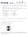
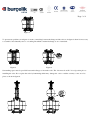
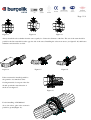
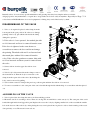
0425
Q1-0143
CONCENTRIC TYPE (SOFT SEATED) BUTTERFLY VALVE MAINTENANCE
Page -1 / 9
OPERATION MANUAL AND WARRANTY DOCUMENT
I . SELECTION – CONTROL PRINCIPLES
Please review the following points in order to asssure that product purchased is suitable for your use and can be
installed and operated properly.
-
Nominal Diameter (DN),
-
Nominal Pressure (PN),
-
Flange Connection Standards
-
Face to Face Standards
-
Conformity of the valve actuation mechanism as stated in the order
-
Temperature limits
-
Fluid Characteristics (Solvent, corrosive, abrasive,...)
-
Control of the valve functions at acceptance (against damage, breaks and existing possible cracks, ...)
USEFUL POINTS TO BE CARED ABOUT DURING OPERATION
-
Valve should be handled carefully during transportation, to avoid any damage, breaks, existing possible cracks.
-
Do not expose the valves to sun and heat; avoid storing in dusty places.
-
Keep the valves at %10 open position while it is in stock.
-
Do not use the valve before reading the catalogues and usage principles.
-
Do not use the valves in exceeding pressure than specified in the order.
-
Valves can be used also for proportional control.
-
Since butterfly valves are quarter turn (90°) on-off valves, do not close the valve suddenly at high flow rates in
order to avoid damage from sudden fluid expansion and water hammer.
-
Concentric type valves are bi-directional and they prevent leakage in both directions.
-
Leave enough space for lever, gearbox or other control systems in the line during the mounting in order to use
the valve properly.
-
Connecting pipe and flange dimensions must comply with the valve standards.
-
Do not weld any parts in the immediate vicinity of the valve. Welding will damage the soft seats and seals of
the valves.
0425
-
Q1-0143
Check the line for iron, stone or any other particles that might damage the valve seats and seals
Page -2 / 9
elements before installing valve. Install the valve at open position on a new pipeline and clean inside of the line before
operating the valve.
-
Do not load any bending, cutting or moment pressures caused by pipeline design on the valve.
-
While doing maintenance or adjustment, check the position of mark at the top of the stem which shows the position of
the disc.
-
Examine label information on the valve which shows the limitation of the valve.
Abbreviation in the valve label:
DN
: Nominal Diameter
PN
: Nominal Pressure
BO
: Body Material
DI
: Disc Material
LI
: Seat Material
ST
: Stem Material
MWP : Max. Working Pressure
ºC
: Max Working Temperature
MD
: Manufacturing Year
STN
: Related Standard
SNo
: Serial Number
!... It is extremely dangerous to do any maintenance, adjustment or any repair while the valve in operation and there is fluid
inside.
!... It is extremely dangerous to do keep in touch with any working parts of the valve while it is operating.
INSTALLATION OF THE VALVE TO THE LINE
Welded neck type flanges are advised (Figure-1).
(FIGURE-1)
Figure-1
If flat pipe flange is used, pipe should be inserted and welded at the inner surface of the flange. Surface should be cleaned by
fine grinding after welding. When the surface is not smooth and there is possibility to damage the rubber seat, then it is advised
to put an O-ring between them (Figure-2)
0425
Q1-0143
Page -3 / 9
Figure-2
To prevent any problems as in figure-4, mount a metal ring between the flange and the valve as in figure-3 when it is necessary
to assemble a new butterfly valve to a working line which contains flat flange as out of standards.
Figure-3
Figure-4
Surrounding space must be provided between the flanges to insert the valve. The disc must be at 95% closed position prior to
installing the valve. Do not place the valve by hammering which may damage the valve or rubber seat may come out of its
place as shown in figure-6.
0425
Q1-0143
Figure-5
Page -4 / 9
Figure-6
After the valve is placed between the flanges, bolts should be inserted, but nuts should not tightened as in figure-7. Open the
valve fully and centre before tightening the nuts, then bolts are screwed until metal to metal contact achieved between valve
body and the flanges as in figure 8. Valve should be absolutely open during this operation, otherwise disc will embed to the seat
and torque value will increase during the starting operation of the valve.
Figure-7
Figure-8
Figure-9
Bolts must be tightened in a crosswise direction and approximately with the given specified torque values during installation
TORQUES FOR BOLTS
DN
50
65
80
100
125
150
200
250
300
TORQUE
Nm.
33
38
42
45
48
62
72
88
110
DN
TORQUE
Nm.
350
120
400
130
450
150
500
160
600
210
700
245
800
295
900
390
1000
500
3
5
Nm
8
1
2
7
6
4
Figure-10
Downstream and upstream pipelines connected to the valve must be in the same axis. Flange surfaces at the entrance and exit of
the valve must be parallel to each other. Flange holes must correspond to each other as in figure-10. Otherwise, installing
becomes difficult and leakage problems occur as in figure-11 and disc hits inside of the pipe-line and , if there is any, actuation
and automatic control units might be damaged as in figure-12.
0425
Q1-0143
Page -5 / 9
Figure-11
Figure-12
Figure-13
Always install the valves further from the curve equally 3 to 5 times the diameter of the line. The axis of the stem should be
parallel to the line extended from the opposite side of the curve. Installing the valves near curves (see figure15-16) shall cause
turbulence and should be avoided.
Figure-14
Figure-15
Figure-16
Figure 14
Figure-15
Figure-16
If the stem must be installed parallel to
the ground to accommodate dense
flowing materials, lower part of the disc
should open in the same direction of
the flow as in figure-17.
Figure-17
For the installing of DN 600 and
above size valves, place valve stem axis
parallel to ground(Figure 18).
0425
Q1-0143
Figure-18
Page -6 / 9
INSTALLING THE VALVE ON EXISTING LINES
1. In order to make mounting easier, open the flanges completely, use a flange separator if necessary
2. Disc must be in 95% closed position
3.
Centre the valve between the flanges and insert the bolts and do not tighten the nuts
4. Open the valve completely and remove the flange separator, if there is any
5. Tighten the bolts using the nuts by hand only.
6. Bring the valve to full open position and test the valve by opening and closing several times)
7. Tighten the bolts until flanges touch the valve body
INSTALLING THE VALVE ON A NEW LINE
1. Connect the valve between the two flanges with bolts while the disc is in a 95% closed position (you may use an apparatus
in the same size instead of valve).
2. Weld the flange of the line only at 2 points. Remove the valve. Continue to weld the flange fully on the line. To avoid heat
damage of rubber seat, never weld the flange while the valve is on line.
3. Loosen the bolts and remove the valve from between the flanges
4. Carefully weld the flange on the line and wait for cooling.
5.
Use welding gauge apparatus for valves over DN 200 sizes.
6.
Repeat the above instructions for installing the valve on the existing line.
7. Use dismantling tools for valves over DN 200 sizes.
REMOVING THE VALVE FROM THE LINE
1. Stop the flow off fluid and discharge the fluid from the line
2.
Bring the valve to 95% close position
3.
Loosen and remove all bolts which prevent removing the valve from the line
4. Remove the valve by opening space between the flanges
5. Use a separator to remove the valve if jammed due to pressure.
DN50-300 BUTTERFLY VALVES
ASSEMBLING-DISASSEMBLING PRINCIPLES
0425
Q1-0143
Butterfly valves do not need any special maintenance and greasing since they have simpler and more reliable
design properties. Any maintenance or repair due to usage faults can be done easily in anywhere. Especially for Page -7 / 9
valves between DN50-300, there is no need equipment for lifting, they can be lifted easily by hand.
DISASSEMBLING OF THE VALVE
1- Valve to be repaired is placed on the clamp from the
bottom part in the open position. In order not to damage
painting of the body, put a thick cloth inside the clamp
during this operation.
2- If the valve is lever operated , the toothed pin with
no 14 is loosened and lever is removed from the stem.
If the lever is tightened to the stem, then use a
screwdriver to remove the lever and do not damage
the painting. Then bolts with no 12 are loosened and
then notch plate with no 10 is removed from the
valve. If the valve has gearbox or actuator, bolts with
no 12 are loosened and then system is removed from
the valve.
3- Screws with no 9 and stopper disc with no 8 are
removed.
4- Valve body is disconnected from the clamp to remove
the stem with no 6. Then the body is connected to the
clamp from the square side of the valve. By holding the
body, stem is removed by pulling
5- Valve is then secured to clamp in the previous position again and then disc with no 3 is removed.
6- To remove seat with no 2, the outer part of the seat is bended through inside with the help of a screwdriver and then placed
out.
ASSEMBLING OF THE VALVE
1- Valve is placed into the clamp the same as in disassembling position.
2- Mount the seat No 2 according to holes. There are one big and one small holes on the seat (no-2). The outer part of the seat is
bended through inside from bigger hole part. Replace the seat to the body by aligning smaller hole of the seat with the smaller
hole at the bottom of the valve body. After placing the seat, stem is placed into its place in order to check centring of the seat is
done perfectly or not. Then stem is removed out.
0425
Q1-0143
3- After mounting the O-ring and bushing with no 4 and 5, respectively, into the body, stem with no 6 is inserted
through the top flange and not inserted all the way through.
Page -8 / 9
4- To place the disc easily into body, silicon oil and soap should be applied on the seat. Then circle hole on the disc will be
placed to the top area and square hole will be placed to the bottom area and then centred with the stem. While doing this
operation, be sure that stem square and disc square correspond to each other. Do not damage seat during this operation.
5- After circlip with no 8 is mounted to seat, washer (no 8) with bolt (no 9) is also mounted to its place.
6- Notch plate (no 10) is tightened to its place with bolts (no 12) while the valve is at open position and bolts are not screwed
yet.
7- Mount lever (no 13) to stem, and position the notch plate at OPEN position.
8- Then tighten the bolts (no 12) and toothed pin (no 14).
9- Finally open-close and pressure tests are done and the valve is ready for installation.
DN350-600 BUTTERFLY VALVES
ASSEMBLING-DISASSEMBLING PRINCIPLES
It is advised to use crane to do maintenance and repair operations for the DN 350- 600 butterfly valves. During repair and
maintenance operations be careful not to damage paintings and sensitive parts of the valve. To prevent any damage, valve must
be put on a wooden or plastic assembly table.
DISASSEMBLING OPERATION
1- Bring the valve at partially open
position.
2-Control units of the valve are
removed.
3-Bolts (no 2 and 16) are removed and
covers (no 11 and 15) are
disassembled from their places.
!....During this operation or removing
the stem, because of air pressure
captured in the disc or fluid flow
pressure , stem and covers may come
out suddenly and may cause
dangerous situations. Thus, while the
bolts are loosened, check whether if
there is any stem pressure above the
covers. Take necessary safety cautions
to prevent it.
0425
Q1-0143
4-Pulling apparatus is used for removing the stem (no 13).
5-To remove stem (no 10), place a stick to the place of tem no.13 and remove the stem no 10 by hammering it Page -9 / 9
gently.
6-Bring the disc (no 4) at open position and remove it by pushing.
7-To remove seat (no 2), place the valve body at a straight up position on the top flange. Bend the outer part of the seat through
inside and remove the seat.
8-Position no 3,5,6,7 bushing and position no 8,9,14 O-rings are removed .
After above steps, maintenance can be done.
ASSEMBLING OPERATIONS
1-To place the seat (no 2) on the body, place the valve body at a straight up position on the top flange. There are one big and
one small holes on the seat. The outer diameter part is bended through inside from the small hole section. Seat is placed into
the body in such a way that big hole on the seat is centred with the big hole in the top flange.
2-Position no 5,6,7,8,9 bushing and O-ring are mounted to the body and then stem (no 10) is mounted in order to test
centring operation is done in a perfectly or not. After testing, stem is removed again.
3-Bushing (no 3) is placed into disc (no 4).
4- To mount the disc into the body easily, silicon oil or soap can be applied into the seat. Then disc is placed to the body as
its hole is contact with top flange. While doing this operation, disc and body holes must coincide each other and seat must
not be damaged.
5-Seat (no 13) is mounted to its place, if required PTFE hammer is used to replace it perfectly.
6-To place the stem (no 10); place the valve upside down or put it on the ground. While placing the stem, be careful that
wedge direction(no 17) is parallel to disc. If required PTFE hammer can be used to place valve perfectly.
7- Mount the covers (no 11 and 15) and tighten the bolts.
8-Valve disc is bring to fully open position by hand and wedge (no 17) is mounted.
9-Control system is brought to an open position and then assembled to valve, joint bolts are tightened.
10- Test the valve by opening and closing several times and then valve is ready for installation.
WARRANTY
Burçelik Vana conducts quality assurance under ISO 9000 certified quality system. This product conforms to the
Burçelik inspection standard. In the event that this product should fail within one (1) year from the original date of
purchase through normal use conforming to the User’s Manual provided with the product , we will repair or replace
at our option ,free of charge ,upon its prepaid return to Burçelik with this Warranty document.
0425
Q1-0143
Page -10 / 9