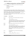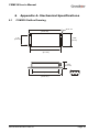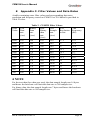
1
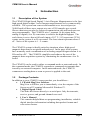
CXM539 User’s Manual
Revision A, March 2005
Document 7430-0114-01
Crossbow Technology, Inc., 4145 N. First Street, San Jose, CA 95134
Tel: 408-965-3300, Fax: 408-324-4840
email: [email protected], website: www.xbow.com
©1999-2005 Crossbow Technology, Inc. All rights reserved. Information
in this document is subject to change without notice.
Crossbow and SoftSensor are registered trademarks and DMU is a
trademark of Crossbow Technology, Inc. Other product and trade names
are trademarks or registered trademarks of their respective holders.
CXM539 User’s Manual
Table of Contents
1
Introduction ............................................................................... 1
1.1
1.2
Description of the System............................................................. 1
Package Contents.......................................................................... 1
2
Electrical and Mechanical Interface........................................ 2
3
Quick Start................................................................................. 3
3.1
3.2
3.3
3.4
4
MagView Software ....................................................................... 3
Connections .................................................................................. 3
Setup MagView ............................................................................ 4
Take Measurements ...................................................................... 4
System Startup and Checkout.................................................. 5
4.1
4.2
Startup Using a Terminal Emulator Program................................ 5
System Checkout .......................................................................... 5
5
CXM539 Configuration and Data Formats ............................ 7
6
Appendix A. Mechanical Specifications ................................ 10
6.1
7
CXM539 Outline Drawing ......................................................... 10
Appendix B. CXM539 Commands ........................................ 11
7.1
7.2
7.3
User Commands.......................................................................... 11
EEROM Map .............................................................................. 12
Software Data Correction Equations........................................... 14
8
Appendix C. Filter Values and Data Rates ........................... 15
9
Appendix D. Warranty and Support Information ............... 16
9.1
9.2
9.3
9.4
Customer Service........................................................................ 16
Contact Directory........................................................................ 16
Return Procedure ........................................................................ 16
Warranty ..................................................................................... 17
Doc.# 7430-0114-01 Rev. A
Page iii
CXM539 User’s Manual
About this Manual
The following annotations have been used to provide additional
information.
; NOTE
Note provides additional information about the topic.
EXAMPLE
Examples are given throughout the manual to help the reader understand the
terminology.
IMPORTANT
This symbol defines items that have significant meaning to the user
WARNING
The user should pay particular attention to this symbol. It means there is a
chance that physical harm could happen to either the person or the
equipment.
The following paragraph heading formatting is used in this manual:
1 Heading 1
1.1 Heading 2
1.1.1 Heading 3
Normal
Page iv
Doc.# 7430-0114-01 Rev. A
CXM539 User’s Manual
1
Introduction
1.1 Description of the System
The CXM539 High Speed Digital 3 Axis Fluxgate Magnetometer is the first
high-speed digital output 3-axis fluxgate magnetometer to be commercially
available. The system can convert and transmit over its serial port (at
38400 baud) all three axes outputs at a rate of 250 samples per second.
Slower data rates can also be selected; transmission rate and baud rates are
user programmable. The CXM539 uses 3 separate 16-bit sigma delta
analog to digital (A to D) converters to achieve the high throughput. The
scale factor is set so that a full scale input of 10-4 T (1 G) represents 32768
counts on the system A to D converters. The least count represents about 3
nT. Noise of the system is 1 - 2 counts.
The CXM539 system is ideally suited to situations where high speed
magnetic data must be acquired and analyzed. In the past, such systems
have normally used a combination of an analog output fluxgate and an A to
D board in a PC. The CXM539 simplifies and reduces the cost of the
magnetic data acquisition system by eliminating the cumbersome A to D
board.
The CXM539 can be used in either a command mode or autosend mode. In
the command mode, the CXM539 responds to commands to transmit data
issued by an external computer. In the autosend mode, the CXM539
commences sending data as soon as power is applied to the unit.
1.2 Package Contents
In addition to your CXM539 sensor product you should have:
• 1 CD with MagView Software
MagView will allow you to immediately view the outputs of the
Sensor on a PC running Microsoft® Windows™.
• 1 Digital Signal Cable.
This links the Sensor directly to a serial port. Only the transmit,
receive, power, and ground channels are used.
•
1 User’s Manual
This contains helpful hints on programming, installation, valuable
digital interface information including data packet formats and
conversion factors.
Doc.# 7430-0114-01 Rev. A
Page 1
CXM539 User’s Manual
2
Electrical and Mechanical Interface
The CXM539 is powered from a single input voltage that can range
between +7.5 V and +15 VDC. Current consumption is 100 mA. Two
serial interfaces are available; one that uses RS-232 levels and one that uses
TTL levels. The baud rate is user programmable and can be set at the
following values: 300, 1200, 2400, 4800, 9600, 19200, 38400, and 72800.
The data words employ 8 bits with one stop bit and no parity.
A female 9 pin D connector is used to provide an electrical interface to the
CXM539 system. The Pin out of this connector is shown in Table 1.
Table 1. CXM539 Connector Pin Out
Pin
Function
1
Not used
2
RS-232 Transmit Data
3
RS-232 Receive Data
4
Not used
5
Ground
6
TTL Serial Out
7
TTL Serial In
8
Factory Use Only
9
Input Power (7.5V to 15VDC)
A drawing showing the dimensions and mounting hole location of the
CXM539 is shown in Appendix A.
Doc.# 7430-0114-01 Rev. A
Page 2
CXM539 User’s Manual
3
Quick Start
3.1 MagView Software
The purpose of the Sensor interface program is to provide a graphical
output interface to the CXM539 Magnetometer and allow the user to
configure and operate the sensor.
The MagView interface program allows the sensor to be monitored in every
mode that the sensor can be programmed. The sensor can be programmed
to allow for ASCII or BINARY transfer mode and corrected or noncorrected data. Log files of sensor data can be created. A scrolling graph of
the digital data and graphical indicators of the angular data are displayed to
the operator. Minimum and maximum values are maintained for the
magnetometer and the accelerometers.
3.1.1
MagView Computer Requirements
The following are the minimum capabilities that your computer should have
in order to run MagView successfully:
•
CPU: Pentium Class
•
RAM: 32MB minimum, 64MB recommended
•
Operating System: Windows 98, NT4, 2000, XP
3.1.2
Install MagView
To install MagView software on to your computer:
1. Insert the CD “Support Tools” in the CD-ROM drive.
2. Find the MagView folder and copy it over to your desktop and the
software ready to use.
If you have any problems or questions, you may contact Crossbow directly.
3.2 Connections
The CXM539 is shipped with a ribbon cable to connect the sensor to a PC
COM port.
1. Connect the 9-pin end of the digital signal cable to the port on the
CXM539.
2. Connect the other 9-pin end of the cable (with backshell) to the
serial port of your computer.
3. The additional black and red wires on the cable supply power to
the Sensor. Match red to (+) power and black to (-) ground. The
Doc.# 7430-0114-01 Rev. A
Page 3
CXM539 User’s Manual
input voltage can range from 7.5-15 VDC. See the specifications
for your unit.
WARNING
Do not reverse the power leads! Applying the wrong power to the Sensor
can damage the unit; Crossbow is not responsible for resulting damage to
the unit.
3.3 Setup MagView
With the Sensor connected to your PC serial port and powered, open the
MagView software.
1. From the MagView main display, click on “Configure” button and
select the correct COM port, Baud Rate (default is 9600) and
Sensor model.
2. You can log data to a file by entering a data file name.
3. You can also administer various Sensor Settings and Special
Settings via this Configure screen and save settings.
4. The main screen provides the graphical visualization of various
sensor parameters that can be checked from “Graph” menu.
5. The “Monitor” window allows the user to view the data being sent
from the sensor and allows the operator to send commands to the
sensor.
3.4 Take Measurements
Once you have configured MagView to work with your sensor, pick what
kind of measurement you wish to see. “AutoData” will show you the output
you choose as a strip-chart type graph of value vs. time. “DataOnce” issues
the command to send the data one time. “Monitor” window allows the user
to view the data being sent from the sensor and allows the operator to send
commands to the sensor.
Doc.# 7430-0114-01 Rev. A
Page 4
CXM539 User’s Manual
4
System Startup and Checkout
4.1 Startup Using a Terminal Emulator Program
Connect the CXM539 to serial port of a PC as described in Section 3.2.
Connect a power supply (+7.5 V to +15 V) to the red (positive) and black
banana plug on the cable.
Start up a terminal emulator program on the PC, e.g. Windows
HyperTerminal, PC Plus, etc. Configure the terminal emulator program for
direct connect to an available com port and select the baud rate 9600 with
one stop bit and no parity.
Apply power to the system and check to see that the unit transmits a start up
message:
APS 539 V1.12.
4.2 System Checkout
After the CXM539 is operational and communicating with a computer, its
proper operation can be qualitatively checked out by using it to measure the
earth’s magnetic field. Around the globe, the magnitude of the earth’s
magnetic field varies from about 0.4 Gauss to 0.6 Gauss. In the northern
hemisphere, the field points north and dips into the ground (dip angle) at
about 60°.
Point the X axis generally north and down at an angle of 60° from
horizontal. Verify that the X axis reads about 0.5G and the Y and Z axis is
read near zero. Repeat the measurement with the Y and Z axes in turn
pointed into the field and verify that these two axes correctly read the
earth’s magnetic field magnitude.
If a terminal program is used before checking the system operation, ensure
that the following commands are given:
M = T <CR> <LF>
M = C <CR><LF>
A <CR> <LF>
Doc.# 7430-0114-01 Rev. A
Page 5
CXM539 User’s Manual
These commands set the transmission mode to be autosend calibrated text.
After issuing the A command, the terminal output will display the
continuous output from the CXM539. Orient the system in the earth’s
magnetic field to verify proper operation as discussed above.
Doc.# 7430-0114-01 Rev. A
Page 6
CXM539 User’s Manual
5
CXM539 Configuration and Data Formats
The user can configure the CXM539 system in the following ways:
1. Mode
2. Autosend or command
3. Baud rate
4. Pacing
The mode settings are used to change the format of the data output. The
user can select the data output to be raw A/D counts (M=R) or calibrated
(in Gauss) (M =C) data. The serial output format can be selected to be text
(M=T) or binary (M=B). The user can also choose whether to append a
checksum to the transmission (M=E) or omit this (M=N).
Some examples of different data output formats and the commands used to
create them are as follows:
Commands
Data Formats
M=T
M=R
M=N
Raw data in a text hex format without a checksum:
X Y Z
1234 5678 9ABC <CR><LF>
The X,Y,& Z values are encoded as four digit hex values
separated from each other with a single space. The last
digit of the Z data is followed by a carriage and a line
feed.
Raw data in a text hex format with a checksum (cs):
X Y
Z cs
1234 5678 9ABC 4E <CR><LF>
This just like the last example except for an addition of a
space and a two digit checksum in Hex between the last
digit of Z and the carriage return. The checksum is
composed of the sum of all of the digits in the X,Y,& Z
data values.
M=T
M=R
M=E
M=T
M=C
M=N
Corrected data in a text decimal format without a
checksum:
X
Y
Z
0.23456 0.78900 0.23997 <CR><LF>
Doc.# 7430-0114-01 Rev. A
Page 7
CXM539 User’s Manual
M=T
M=C
M=E
The X,Y,& Z values are encoded as decimal values in
Gauss. Each is separated from the next with a single
space. The last digit of the Z data is followed by a
carriage return and a line feed.
Corrected data in a text decimal format with a checksum:
X
Y
Z cs
0.23456 0.78900 0.23997 4C <CR><LF>
This is just like the last example except for an addition of
a space and the two-digit checksum in Hex between the
last digit of Z and the carriage return. The checksum is
composed of the sum of all of the digits in the X,Y,& Z
data values.
M=B
M=R
M=N
Raw Data in a binary format without a checksum:
X
Y
Z SB
12 34 56 78 9A BC 5A <CR> <LF>
The X,Y,& Z values are each encoded as a two byte
value. The X, Y, Z data is followed by a constant
synchronization byte (SB) of 5A.
M=B
M=R
M=E
Raw data in a binary format with a checksum:
X
Y
Z
cs SB
12 34 56 78 9A BC AE 5A <CR><LF>
IMPORTANT
When in Binary mode, the X, Y & Z values for magnetometer data are
encoded as a signed integer, 2's complement, with a conversion factor of
(MSB * 256 + LSB ) in Gauss
M x or M y or M z =
215
This is followed by a checksum consisting of the lower eight bits of the sum
of the bytes comprising the X, Y & Z Data and calculated as
Checksum =
sum of all bytes except checksum and 5A
256
This is followed by a synchronization byte of 5 A, which represents the end
of the data packet.
Doc.# 7430-0114-01 Rev. A
Page 8
CXM539 User’s Manual
To determine the mode of a CXM539, issue the command M?
The autosend command (A) enables data to be sent continuously upon
power on. The output rate of the sent data is set by the pacing variable,
which can vary from 0000 (full speed) to FFFF (very slow). Pacing values
are set by commands of the form:
P = XXXX <CR><LF>
The filter value for A/D can be set and the data rate can be accordingly
changed by,
F = XXXX <CR><LF>
Different filter values and corresponding data rates, resolution and
frequency are provided in Appendix B.
The user can set the baud rate of the CXM539 to the standard values from
300 to 76800 baud. The baud rate command is of the form:
B = XXXX <CR><LF>
A complete list of the CXM539 commands can be found in Appendix B.
Doc.# 7430-0114-01 Rev. A
Page 9
CXM539 User’s Manual
6
6.1
Appendix A. Mechanical Specifications
CXM539 Outline Drawing
4.08”
(10.4 cm)
4X Φ 16
1.10”
(2.8 cm)
1.60”
(4 cm)
3.70”
(9.4 cm)
1.125”
(2.9 cm)
1
3.32” (8.4 cm)
4.08”
(10.4 cm)
Doc.# 7430-0114-01 Rev. A
Page 10
CXM539 User’s Manual
7
Appendix B. CXM539 Commands
7.1 User Commands
All commands must be followed by a return.
All changes to the mode value are saved as the power-up mode.
M?
M=R
M=C
M=B
M=T
M=E
M=N
A
S
D
B?
B=#####
P?
P=####
E?
E####
W####XX
C
I
*
?
Send the current mode value.
All Data is Sent as raw A/D Counts in ASCII four digit
Hex values or Binary Values depending on the current
mode.
All Data is Sent as Gammas, Formatted as base Ten fixed
point Text or Binary Values depending on the current
mode.
Set Data is Formatted as Binary Numbers.
Set Data is Formatted as Text Numbers.
Send a checksum with all Data.
Don't Send a checksum.
Start Auto Send Data.
Stop Auto Send.
Send the current Data Value.
Send the run mode Baud Rate.
Set Run Mode Baud Rate 300 - 76800 Baud is accepted.
In Config Mode the baud rate is always 9600.
Display the current pacing value.
Set a Pacing value to slow the data rate.
Send All EEROM Data.
Send EEROM Data followed by 4 hex digits address and
optional 2 digits representing the number of bytes to send.
Write EEROM Data followed by a 4 hex digit address
and 2 hex digits of Data.
Reset and Calibrate A/D(s).
Send ID and many internal values.
Reset and Restart Sensor.
Display Help.
Doc.# 7430-0114-01 Rev. A
Page 11
CXM539 User’s Manual
7.2 EEROM Map
For all EEROM constants the least significant byte is stored in the lowest
address and the most the most significant byte is stored in the highest
address.
00
01
02
03
Not Used
CPU Clock Speed Divisor
1-7 Clock Divisor
8- 0=Run at Full clock speed 1=Enable clock division
CPU Speed = 4.9152 MHz/(129-ClockDivisor)
This used to allow the use of lower UART baud rates and
Lower power consumption.
For example 300 baud could be used with the Clock
Divisor set to 125 to divide the clock rate by 4 and the
baud rate control register set to 255.
Operating Mode
1- Send Corrected Data.
2- Autosend Data until Stop autosend command received.
3- Send Data Only Once (On power up or single data by
command)
4- Send Data in a Text Format
5- Send Data in a decimal format (Only checked if in Text
format)
6- Calibration Mode 000 - Run Mode 001 - Unlocked
010 - Zero Mode
7- Calibration Mode 011 - XField 100 - YField 101 ZField
8- Calibration Mode 110 - Field Delta
More Operating Mode
1- Send Check Sum with Data
2- Not Used
3- Not Used
4- Not Used
5- Not Used
6- Not Used
Doc.# 7430-0114-01 Rev. A
Page 12
CXM539 User’s Manual
7- Not Used
8- Not Used
04
05
06-07
08-09
0A-0B
0C-0D
0E-0F
10-11
12-13
14-15
16-17
18-19
1A-1B
1C-1D
1E-1F
30-32
33-35
36-38
39-3B
3C-3E
3F-41
42-43
Baud Rate Control
BaudRate = 4.9152Mhz / 16*(BaudRateControl+1)
Values for Common Baud Rates with no clock dividing:
1200: 255(FFH) 19200: 31(1FH)
2400: 127(7FH) 38400: 7(7H)
9600: 63(3FH) 76800: 3(3H)
Not Used
Soft Offset X
Soft Offset Y
Soft Offset Z
Soft Scale X
Soft Scale Y
Soft Scale Z
Soft Ortho XY
Soft Ortho XZ
Soft Ortho YX
Soft Ortho YZ
Soft Ortho ZX
Soft Ortho ZY
Pacing Value
A/D Offset Calibration 0 Set When the A/D is Calibrated
A/D Gain Calibration 0 Set When the A/D is Calibrated
A/D Offset Calibration 1 Set When the A/D is Calibrated
A/D Gain Calibration 1 Set When the A/D is Calibrated
A/D Offset Calibration 2 Set When the A/D is Calibrated
A/D Gain Calibration 2 Set When the A/D is Calibrated
Filter Settings (Set for Data Rate Vs Data Noise)
01- FAST Mode Enabled
02- Skip Mode Enabled
03- Chop Mode Enabled
04- Must Be 0
Doc.# 7430-0114-01 Rev. A
Page 13
CXM539 User’s Manual
05-16- 12 bit Sync Filter
7.3
Software Data Correction Equations
Xout = ((((Xin + XOffset) * XScale)/32768)+
((((Yin + YOffset) * YScale)/32768) * YOrtho)+
((((Zin + ZOffset) * ZScale)/32768) * ZOrtho))/65536
Yout = ((((Yin + YOffset) * YScale)/32768)+
((((Xin + XOffset) * XScale)/32768) * XOrtho)+
((((Zin + ZOffset) * ZScale)/32768) * ZOrtho))/65536
Zout = ((((Zin + ZOffset) * ZScale)/32768)+
((((Xin + XOffset) * XScale)/32768) * XOrtho)+
((((Yin + YOffset) * YScale)/32768) * YOrtho))/65536
Doc.# 7430-0114-01 Rev. A
Page 14
CXM539 User’s Manual
8
Appendix C. Filter Values and Data Rates
A table containing some filter values and corresponding data rates,
resolution and frequency tested on CXM539 at 38.4 kbaud is provided in
Table 2 below.
Filter
Value
Text
Data
rate
(/sec)
Table 2.
Binary
Data
rate
(/sec)
8000
6000
4000
3000
2000
1800
1000
900
800
600
400
300
150
200
240
240
240
240
240
240
240
240
240
240
150
200
300
370
370
370
370
370
370
370
370
370
CXM539 Filter Values
Raw
A/D
A/D
Binary
Sample Resolution
data
rate
in bits
rate
(/sec)
(/sec)
150
150
17.5
200
200
17
300
300
17
400
400
16.5
548
600
16.5
548
800
16
548
1200
15.5
548
1600
15
548
2400
14
548
3200
13
548
4800
12
548
6400
11
-3db
Frequency
(Hz)
39.3
52.4
78.6
104.8
157
209
314
419.2
629
838.4
1260
1676
; NOTE
For the text data (hex data was sent), the data sample length was 16 bytes
and hence the baud rate will limit the data rate to 240 samples/sec.
For binary data, the data sample length was 7 bytes and hence the baud rate
will limit the data rate to 548 samples/sec.
Doc.# 7430-0114-01 Rev. A
Page 15
CXM539 User’s Manual
9
Appendix D. Warranty and Support
Information
9.1 Customer Service
As a Crossbow Technology customer you have access to product support
services, which include:
9.2
•
Single-point return service
•
Web-based support service
•
Same day troubleshooting assistance
•
Worldwide Crossbow representation
•
Onsite and factory training available
•
Preventative maintenance and repair programs
•
Installation assistance available
Contact Directory
United States:
Phone:
Fax:
Email:
Non-U.S.: refer to website
9.3
1-408-965-3300 (8 AM to 5 PM PST)
1-408-324-4840 (24 hours)
[email protected]
www.xbow.com
Return Procedure
9.3.1
Authorization
Before returning any equipment, please contact Crossbow to obtain a
Returned Material Authorization number (RMA).
Be ready to provide the following information when requesting a RMA:
•
Name
•
Address
•
Telephone, Fax, Email
•
Equipment Model Number
•
Equipment Serial Number
•
Installation Date
•
Failure Date
•
Fault Description
Doc.# 7430-0114-01 Rev. A
Page 16
CXM539 User’s Manual
9.3.2
Identification and Protection
If the equipment is to be shipped to Crossbow for service or repair, please
attach a tag TO THE EQUIPMENT, as well as the shipping container(s),
identifying the owner. Also indicate the service or repair required, the
problems encountered, and other information considered valuable to the
service facility such as the list of information provided to request the RMA
number.
Place the equipment in the original shipping container(s), making sure there
is adequate packing around all sides of the equipment. If the original
shipping containers were discarded, use heavy boxes with adequate padding
and protection.
9.3.3
Sealing the Container
Seal the shipping container(s) with heavy tape or metal bands strong enough
to handle the weight of the equipment and the container.
9.3.4
Marking
Please write the words, “FRAGILE, DELICATE INSTRUMENT” in
several places on the outside of the shipping container(s). In all
correspondence, please refer to the equipment by the model number, the
serial number, and the RMA number.
9.3.5
Return Shipping Address
Use the following address for all returned products:
Crossbow Technology, Inc.
4145 N. First Street
San Jose, CA 95134
Attn: RMA Number (XXXXXX)
9.4 Warranty
The Crossbow product warranty is one year from date of shipment.
Doc.# 7430-0114-01 Rev. A
Page 17
Crossbow Technology, Inc.
4145 N. First Street
San Jose, CA 95134
Phone: 408.965.3300
Fax: 408.324.4840
Email: [email protected]
Website: www.xbow.com