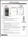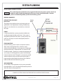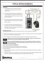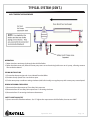
1
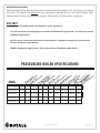
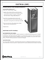
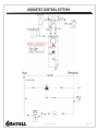
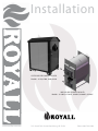
Installation OUTDOOR PRESSURIZED BOILER Models: 6150, 6200, 6300, 6490 INDOOR PRESSURIZED BOILER Models: 6130NS, 6150NS, 6200NS, 6300NS, 6490NS www.royallfurnace.com 325 South Park Street Reedsburg, WI 53959 Phone 608-768-8508 Thank you for purchasing a ROYALL pressurized Solid Fuel appliance. Boilers are a quality Solid Fuel Appliance designed to effectively heat structures. Please read and follow all safety instructions to ensure optimal performance. The installation and operation of the is quite simple. Nevertheless, we recommend that the instructions be carefully read and followed. On INDOOR models, pay particular attention to the chimney and chimney connector installations as they present a significant fire danger. If you have any questions on the installation or operation of your Solid Fuel Appliance, please contact your local representative. Failure to install properly, or follow safety instructions could result in severe personal injury, death or substantial property damage. HAZARD DEFINITIONS OBSERVE AND FOLLOW ALL SAFETY INSTRUCTIONS The following defined terms are used throughout this manual to bring attention to the presence of hazards of serious risk levels, or important information concerning the life of the product. DANGER Dictates presence of hazards that WILL CAUSE SERVER personal injury, death or substantial property damage. WARNING Indicates presence of hazards that CAN CAUSE SERVE personal injury, death or substantial property damage. CAUTION Indicates presence of hazards that WILL OR CAN CAUSE minor personal injury or property damage. NOTICE Indicates special instructions on installation, operation or maintenance that are important but not related to personal injury or property damage. VERIFY WITH YOUR INSURANCE COMPANY AND ALL LOCAL CODES AND ORDINANCES PRIOR TO INSTALLATION. IT IS THE OWNER’S RESPONSIBILITY TO ENSURE THAT THE APPLIANCE MEETS ALL LOCAL CODES AND ORDINANCES. September 2012 Page 2 PRODUCT REGISTRATION CARD Warranty is in effect from the date of purchase upon receipt of this card. NAME STREET ADDRESS CITY STATE ZIP CODE PHONE EMAIL ADDRESS DATE OF PURCHASE MODEL NUMBER SERIAL NUMBER DEALER CITY STATE Reason for choosing Royall over other brands __Price __Features __Safety __Previously owned Royall __Recommended to you __Other PRODUCT REGISTRATION CARD Warranty is in effect from the date of purchase upon receipt of this card. NAME STREET ADDRESS CITY STATE ZIP CODE PHONE EMAIL ADDRESS DATE OF PURCHASE MODEL NUMBER SERIAL NUMBER DEALER CITY STATE Reason for choosing Royall over other brands __Price __Features __Safety __Previously owned Royall __Recommended to you __Other OWNER’S REGISTRATION CARD MUST BE COMPLETED AND RETURNED T0 ROYALL AT TIME OF INSTALLATION. Place Stamp Here Brand Products 325 South Park Street Reedsburg, WI 53959 Place Stamp Here Brand Products 325 South Park Street Reedsburg, WI 53959 CONTENT GENERAL SAFETY.................................................................................................................................................. Pg 4 PRESSURIZED BOILER SPECIFICATIONS.......................................................................................... Pg 5 PRODUCT DESCRIPTION.................................................................................................................... Pg 6 INSTALLATION INSTALLATION TIPS............................................................................................................................. Pg 7 INSTALLATION PLACEMENT.............................................................................................................. Pg 8 CONTENTS............................................................................................................................................ Pg 9 SHROUD INSTALLATION.................................................................................................................... Pg 11 FIREBRICK INSTALLATION.................................................................................................................. Pg 12 INDOOR BOILER INSTALLATION: VENTING..................................................................................... Pg 13 PLUMBING CONNECTIONS................................................................................................................ Pg 15 COMPONENT ASSEMBLY.................................................................................................................... Pg 16 ELECTRICAL......................................................................................................................................... Pg 18 AQUASTAT CONTROL SETTING......................................................................................................... Pg 20 ELECTRICAL DIAGRAMS.................................................................................................................... Pg 21 SYSTEM PLUMBING............................................................................................................................ Pg 22 TYPICAL SYSTEM SCHEMATICS........................................................................................................ Pg 23 START UP INITIAL SYSTEM FILL.......................................................................................................................... Pg 26 FIRST FIRE............................................................................................................................................ Pg 28 OPERATION BOILER CONTROL............................................................................................................................... Pg 28 BURNING WITH WOOD...................................................................................................................... Pg 29 BURNING WITH COAL........................................................................................................................ Pg 30 EMERGENCY ACTIONS....................................................................................................................... Pg 32 MAINTENANCE.................................................................................................................................... Pg 33 TROUBLE SHOOTING................................................................................................................................... Pg 36 REPLACEMENT PARTS LISTING................................................................................................................. Pg 38 WARRANTY..................................................................................................................................................... Pg 42 September 2012 Page 3 SAFETY NOTICE ALL STATE or LOCAL CODES take precedence and MUST be observed. These models have been certified compliant to UL 391-06 through independent testing. Additionally, some of these recommendations align with the National Fire Protection Assign. Code 211. Before installing or starting operation, read and familiarize yourself with all instructions. Installation is to be performed only by qualified licensed heating professional. DANGER RISK OF EXPLOSION OR PERSONAL INJURY DO NOT use chemicals, kerosene or other flammable liquids to start a fire; severe burns could result. DO NOT store combustible liquids or materials near the appliance. DO NOT store wood within the minimum clearance to combustibles. DO NOT burn garbage, gasoline, naphtha or engine oil for any reason. DO NOT burn tires, telephone poles, railroad ties or yard waste. In many areas this is illegal and will damage the appliance. Burning anything other than approved fuels will void any warranties. DO NOT start a fire if flammable vapors or dust are present. An explosion could result. DO NOT use with an automatic stocker. DO NOT operate with a flue draft exceeding .06 inches of water column pressure. Most anti-freeze is glycol based. Never store glycol of any kind near the appliance or any potential ignition source. All glycol is flammable when exposed to high temperatures. If glycol is allowed to accumulate in or around the appliance or any other potential ignition source, a fire can develop. NEVER use automotive anti-freeze or ethylene glycol in the system. Using these glycols can destroy rubber pump and valve seals leading to hazardous leakage and system damage. Monitor and inspect the system and appliance regularly for leakage. NEVER operate without a properly installed pressure relief valve (watts M335 or Apllo 407-1035) or equivalent) which discharge water and relieve pressure at 30 psi. Use only a boiler relief valve designed to lift at 30 psi. Failure to use proper valve could result in an explosion, injury or property damage. WHEN SYSTEM IS COLD, CAREFULLY OPEN/TEST/INSPECT the pressure relief valve at least annually to ensure waterways are clear. IF SYSTEM IS HOT, avoid contact with the scalding water that will be released. Failure to check the valve could result in an over pressure condition. This provides risk of a rupture in the system and significant risk of severe injury or damage. DO NOT install in a garage due to routine presence of flammables. DO NOT use petroleum-based cleaning or sealing compounds in the heating system. Pump and valve water seal deterioration will occur. This can result in substantial property damage. DO NOT use “homemade cures” or “boiler patent medicines”. Serious damage to the appliance, personal injury and /or property may result. To avoid electric shock, disconnect electrical supply before performing maintenance. To avoid server burns, allow the appliance to cool before performing maintenance. This appliance requires electricity whenever in operation. Operation without electricity could result in the appliance overheating. If power outages are anticipated, a back-up electrical generator is recommended. September 2012 Page 4 APPLIANCE OPERATION: Before opening the fuel door to a fired system, ensure that the draft blower is OFF, the damper rod is pulled out, wait 5-10 seconds, and ALWAYS hesitate momentarily between the first and second latches when opening doors to allow unburned gases to ignite. Failure to do so could result in severe burns. DO NOT • Block flow of combustion or ventilation air to the appliance. • Turn off the water circulation pump or prevent fluid flow during operation. An over pressurized condition could result. • Restrict access to the rear of the unit for maintenance. Attempt to supply fuel to these units with an automatic stoker device. • DO NOT attempt to supply fuel to these units with an automatic stoker device. PRESSURIZED BOILER SPECIFICATIONS ) LS HT e ) DE G L I y O m / E M it u h R /H B ac ol s) t R TDOO ER WILER W d p V e b ( g E I e a z x a i n T U T C t( at Di ER Bo Le E L / L (O H E L H B O rS er L e gh im o t e H I g i t r u a S /H S IT e Fi Do Lo Es Fl BO W W W W TU MODEL NUMBER 6130 130,000 780 6.25 cubic ft 26” 10 X 14 6“ 23 gal 24 X 44 X 38 N/A N/A 6150 150,000 905 8.1 cubic ft 26” 10 X 14 6“ 35 gal 26 X 51 X 38 45 X 60 X 77 1415 INDOOR & OUTDOOR 200,000 1250 13.0 cubic ft 26” 17 X 17 6“ 90 gal 36 X 59 X 38 45 X 60 X 77 1760 6300 300,000 1650 17.7 cubic ft 43” 17 X 17 6” 135 gal 36 X 59 X 55 45 X 76 X 77 2530 490,000 2900 50. cubic ft 56” 24 X 32 10” 260 gal 50 X 74 X 74 60 X 90 X 85 4000 INDOOR & OUTDOOR 6200 INDOOR & OUTDOOR 6490 INDOOR & OUTDOOR September 2012 Page 5 PRODUCT DESCRIPTION The Indoor/Outdoor Solid Fuel Boilers are designed to burn either seasoned, split cord wood or coal. A water circulating pump moves the heated water to a heat exchanging device. This can be a base board radiator, finned based board radiator, water to air exchanger, or existing boiler system; with the correct safety apparatus installed to local codes. The wood fire combustion process is controlled by an aqua stat that senses exiting water temperature. The aqua stat is set to the desired high temperature set point and will energize the solid fuel draft fan when the water temperature drops 10 degrees below the high temperature set point. When the water reaches the high temperature set point the aqua stat shuts off the electrical power to the solid fuel draft blower. It is not necessary to connect a thermostat wire from the heating structure to the boiler. The boiler will sustain the desired temperature water so that is available to the heated structure when needed. The operator uses the high temperature setting and fuel load size to match the unit’s heat output with the heated structures needs. If heat is not needed by the structure, full temperature water returning to the unit should put it into a damping cycle until heat is taken by the structure or lost in the system through normal heat loss related to the effectiveness of the system insulation. A master switch should be incorporated such that all power to unit can be controlled. A fan switch or light switch should be incorporated to allow manual shut off during fuel loading and fire box maintenance. A two position safety latch is installed on the fuel door and the ash pan door. Initial release of the latch should be followed by a brief hesitation to allow ignition of unburned gases. Force from the unburned gases igniting can cause the door to abruptly swing open to the 2nd position of the latch which stops further opening forcing the ignition flame and gases to exit the flue instead of out the door. These units should only be installed and operated as closed (pressurized) systems. An expansion tank is required to provide safe changes in water volume related to system temperature change. A pressure relief valve is installed on the unit to safely reduce system pressure if it ever exceeds 30 psi. The appliance is hydrostatically tested at the factory to 60 psi. The solid fuel boiler can deliver hot water to an existing gas, oil or electric boiler or can operate independently via a bypass loop. Water must be continuously pumped through the appliance. The room thermostat cycles the existing boiler, starting the water pump. If the solid fuel boiler is out of wood, the primary boiler aquastat will signal the primary firing system to take over and maintain system temperature. An over temperature relief zone is required. To signal a relief zone exchanger a surface aquastat can be used as a safety limit control. If the water temperature passing through the pipe where the surfaces aquastat is mounted rises above the set point (should be the same or slightly above the high temperature setting of the boiler when attached to the hot supply line). This signal will over ride the normal setting for the exchanger and relieve the system of excess heat. This reduces risk of over pressurizing the system. September 2012 Page 6 INSTALLATION TIPS AVOIDING AIR LOCKS All ROYALL Solid Fuel Boilers are designed not to exceed 30 psi, and will vent to the atmosphere if necessary. Air trapped in the lines prevents circulation. Poor circulation is a common start up problem. Reduced flow can be difficult to detect because the pipes will feel hot. It is essential to provide a means for the air in the lines to escape as the system is being filled. Design piping to avoid high points where air can be trapped or install air bleeding vents at these locations. Various vent fittings are available such as vented brass elbows or baseboard tees. Vents should be open during the fill process. Close the vents when bubble-free water runs out. The auto air vents on top of the air scoop should remain open at all times. Improper venting can lead to risk of generating high temperatures or steam which can destroy DANGER hard and flexible plastic piping due to increased temperature. BALL VALVES Install ball valves in the lines to isolate various components or sections. The ball valves will eliminate the need to drain and refill the entire system should joints need to be resoldered or plumbing modified. Normally, isolation pump flanges are supplied with the pump. These have built in ball valves that can be opened or closed, allowing the pump to be replaced without draining the system. It is recommended that isolation ball valves be installed at the boiler to assist in maintenance. WATER SUPPLY A tee and additional drain valve installed in the system will assist in filling the appliance. Typically the existing boiler system has a keep fill connection already installed. The boiler should be filled the first time according to the initial fill manual section. Ensure that you can adequately monitor system pressure while filling. Ideally, system pressure should be visible from the valve being used to fill the system. Unless a back flow preventer is used with a keep full valve, you will need to disconnect the water supply. Normal routines should include inspecting the entire system for leaks. CORROSION INHIBITOR It is recommended that the system water be tested and PH levels maintained between 8.5 & 11, Use of a corrosion inhibitor is recommended. Treatment reduces premature failure due to corrosion and can help provide efficient heat transfer by minimizing scale. Treatments should be designed for use in hydronic (boiler) systems. Individual water conditions may require unique additives. Unit failure due to severe short term corrosion is not covered by the warranty. RELIEF VALVES WARNING A pressure relief valve must be piped into the appliance such that it can not be isolated from the appliance. Open plumbing (no fitting at the end) should be added to the valve so that release will safely discharge scalding water near the floor. September 2012 Page 7 INSTALLATION PLACEMENT IMPORTANT NOTE • • CHECK WITH INSURANCE COMPANY PRIOR TO INSTALLATION. IT IS THE OWNER’S RESPONSIBILITY TO ENSURE THAT THE APPLIANCE IS ACCEPTABLE TO THEIR INSURANCE CARRIER. VERIFY LOCAL CODES AND ORDINANCES PRIOR TO INSTALLATION. IT IS THE OWNERS RESPONSIBILITY TO ENSURE THAT THE APPLIANCE MEETS ALL LOCAL CODES AND ORDINANCES WHICH TAKE PREEDENCE AND MUST BE OBSERVED PROVIDING THEY ARE MORE RESTRICTIVE. INSTALLATION MUST BE PERFORMED BY A QUALIFIED INSTALLER 1) When placing the Solid Fuel INDOOR Boiler, the following should be considered. a) Review the minimum clearances to combustibles on page 9. b) Review the recommended stack heights on page 13. c) Do not locate near any combustible materials, gasoline or other flammable liquids or gases. d) Check with insurance company and observe local codes and ordinances. e) The unit requires 115V 15 Amp electrical service for operation. DANGER Failure to keep the solid fuel boiler area clear and free of combustible materials, gasoline or other flammable liquids or vapors can result in severe personal injury, death or substantial property damage. SOLID FUEL APPLIANCES SHALL NOT BE INSTALLED IN A LOCATION WHERE GASOLINE OR OTHER FLAMMABLE VAPORS ARE LIKELY TO BE PRESENT. The Indoor boil is designed to be installed inside the building being heated either as a stand alone unit or in combination with another boiler. All installations must be in accordance with local and state codes which may differ from this manual. FOUNDATION The Indoor boiler must be located on a 2” minimum thickness concrete foundation pad. At a minimum, there must be a non-combustible pad (concrete, brick, or paver) the width of the appliance extending out 48 inches from the front of the unit. Outdoor units should be set on a concrete pad capable of supporting the unit when it is filled. A 48” non-combustible surface is recommend in front of the fuel loading door. DANGER A non-combustible pad must be installed in front of the unit to contain any sparks or coals out of the loading door or Ash pan door. Fire can result, causing severe personal injury, death or substantial property damage. FLOORING DANGER The Solid Fuel Boiler must be placed on a non-combustible floor which must extend a minimum of 6 inches on sides and back. 48 inches are required in front. The unit should never be installed on carpeting even if a foundation is used. Fire can result causing severe personal injury, death or substantial property damage. *** DO NOT INSTALL IN A GARAGE WHERE FLAMMABLES ARE STORED *** September 2012 Page 8 CONTENTS INSTALLATION: CLEARANCES – INDOOR MODELS The Indoor boiler must be installed with these minimum clearances from NON-COMBUSTIBLE surface: Front = 30”/ Back = 30” / Sides = 12” The Indoor boiler must be installed with these minimum clearances from any COMBUSTIBLE surface: Front = 48”/ Back = 30” / Smoke pipe / Sides = 18” Recommended maintenance clearances = 18” Back 30 / one side 36 DO NOT CONNECT THIS UNIT TO A CHIMNEY FLUE SERVING ANOTHER APPLIANCE. CHIMNEY TYPE: CLASS “A” ALL FUEL CHIMNEY 8” DIAMETER CLEARANCES: UNIT TO BACKWALL 30” UNIT TO SIDEWALL 18” FLUE TO BACKWALL 18” FLUE TO SIDEWALL 30’ FLOOR PROTECTION: FOR INSTALLATION ON NON-COMBUSTIBLE FLOOR ONLY. MAXIMUM DRAFT: 0.06 IN WATER COLUMN. ELECTRICAL RATING: 120 V., 0.5 AMP, 60 HZ. OPERATION/MAINTENANCE FUEL: BURN SOLID WOOD OR COAL ONLY. LOAD FUEL CAREFULLY OR DAMAGE MAY RESULT. DO NOT STORE FUEL OR COMBUSTIBLES NEAR UNIT. DO NOT USE CHEMICALS OR FLUIDS TO START FIRE, DO NOT BURN GARBAGE, GASOLINE, NAPTHA OR ENGINE OIL. FOR SAFETY, KEEP FUEL AND ASH DOORS TIGHTLY CLOSED. CLEAN HEAT EXCHANGER. FUEL PIPE AND CHIMNEY FREQUENTLY TO PREVENT ACCUMULATION OF SOOT. THE APPLIANCE AND FLUE PIPE MUST BE IN GOOD CONDITION. IN THE EVENT OF A RUN-AWAY FIRE, STOP SUPPLY OF COMBUSTION AIR TO FIRE. SECURE FUEL AND ASH DOORS. REFER TO OWNER’S MANUAL. DO NOT OPERATE DURING POWER FAILURE. September 2012 Page 9 CONTENTS (CONT.) INSTALLATION: INSPECTING CONTENTS BOXED COMPONENTS SHIPPED LOOSE INSIDE (component illustrations located in repair parts section) ROYALL INDOOR BOILER Fire Brick Aquastat Pressure and Temperature Gauge Draft blower and gasket Pressure Relief Valve Spring Handles for doors, shaker grate and damper plate Owners warranty / registration card Installation and Operation Manual BAFFLE PLATE (all boilers) The unit comes with a cast iron baffle installed inside the fire box. Verify that the baffle is in place directly behind the blower mounting opening. GRATES (all boilers) The unit comes with grates installed inside the fire box. Verify that the grates are in place and operate freely. DOOR GASKETS (all boilers) The unit comes with the door gaskets installed in both the fuel door and ash pan door. Verify that they are in place. SMOKE DAMPER (all boilers) The unit comes with the smoke damper assembly installed. Verify that the damper handle moves freely, opening the smoke by pass plate. ASH PAN The unit comes with the ash pan stored in the ash pan trough. Open the ash door and remove the ash pan. The pan should NOT be stored in the unit during operation, as it will warp and be to hot to handle. September 2012 Page 10 SHROUD INSTALLATION 1. Attach Shroud mount corners to Boiler using supplied hardware. Each corner is designed to fit a specific corner of the unit. 2. Attach Shroud side panels to corners. Panels will fit inside the corners. 3. Install Shroud top. Top must be installed before aquastat is installed. Attach with supplied hardware. SHROUD TOP SHROUD MOUNTING CORNER NOTE: SHROUDS ORDERED AS A SET SET INCLUDES: 4 CORNER 2 SIDES 1 TOP HARDWARE SHROUDS ARE UNIQUE FOR EACH UNIT. SHROUD SIDE September 2012 Page 11 FIREBRICK INSTALLATION The appliance comes with the firebrick packaged inside. Brick size: 9” x 4-1/2” x 1-1/4” (Royall pin number firebrick standard split). MODEL 6130 (6) Full Bricks & (2) Cut Brick Starting in the BACK lay 3 full brick then 1 cut brick. Repeat for 2nd side. Model 6130 MODEL 6150 & 6200 (12) Full & (2) Cut Bricks Starting in the BACK of the unit, place ½ brick on end, then add 4 full brick on end. Last lay 2 full bricks side down. Repeat for 2nd side. Models 6150 & 6200 MODEL 6300 (18) Full Bricks & 2 Cut Bricks Starting in the BACK stand 1 cut brick then 7 full brick side by side. Then lay 2 bricks stacked side to side in the front. Repeat for 2nd side. Model 6300 MODEL 6490 (36) Full Bricks Starting at the BACK stand 12 full brick side by side. Then lay 6 full brick down on top of 12 lower ones. Repeat for 2nd side. Model 6490 September 2012 Page 12 INDOOR BOILER INSTALLATION: VENTING All single wall chimneys must be at least 18” from any combustible surface. Fire can DANGER result, causing severe personal injury, death, or substantial property damage. DANGER A major cause of chimney-related fires is failure to maintain required clearances (air spaces) to combustible materials. It is of the utmost importance that all chimneys be installed in accordance with the manufacturer’s instructions. CHIMNEY MATERIAL The Boiler must be connected to either a: 1) Class “A” masonry chimney 2) All Fuel metal insulated chimney (8”) 3) Listed type “HT” double wall chimney approved for temperatures up to 1400 °F (8”) CHIMNEY CONNECTORS Connectors will be required to attach appliance to chimney unless chimney is attached direct. 1) Chimney connector can either be: A) 6” or 8” galvanized, black or blue steel, stove pipe with adapter only at the “T” • Maintain 18” clearance to combustibles. • Minimum thickness: .028 inches (24 gauge minimum) B) 6” or 8” listed type “HT” double wall chimneys. • Maintain 2” clearance to combustibles. 2) Boiler must be the only heating appliance connected to a single chimney flue. 3) Keep the connector as straight and short as possible. A) Minimize elbows. B) Maximum horizontal distance between boiler and chimney: 6 Ft. C) “Male” end should point back to boiler. D) Horizontal runs must be pitched back to the boiler in accordance with local Building Codes (typically 1/4” pitch per Foot of horizontal run minimum). E) Secure each connection with a minimum of 3 screws. 4) Assemble in accordance with the vent manufacturers instructions. Additional sections may be required to clear the peak of the structure. Do not install more than one appliance per flue. When burning coal, a barometric draft damper MUST be installed between the boiler and the chimney to en sure adequate draft. 5) DANGER DO NOT install more than one appliance per flue. Flue gas spillage and carbon monoxide emissions can occur causing severe personal injury or death. CHIMNEY MUST BE INSTALLED OR INSPECTED BY A PROFESSIONAL AND MEET ALL LOCAL AND STATE REQUIREMENTS AND CODES FOR WOOD OR COAL BURNING APPLIANCES OPERATING CONDITIONS. September 2012 Page 13 INSTALLATION: VENTING CHIMNEY HEIGHT To prevent downdrafts, chimney, or vent without a listed cap should extend at least 3 feet above the highest point where it passes through a roof and at least 2 feet higher than any portion of a building within a horizontal distance of 10 feet. A chimney or vent must not extend less than the distances stated above. **Check local codes or ordinances for additional requirements** 2 FT. 2 FT. 10 FT. 3 FT. Nearby structures, trees, or hills can cause downdraft conditions which force smoke to the ground. Chimney height may have to be raised to overcome downdraft conditions. NOTICE Improper use or failure to maintain the boiler may cause nuisance conditions. Persons operating this solid fuel boiler are responsible for operation so as not to cause nuisance conditions. Even proper use and maintenance of the boiler, and meeting the distance and stack height recommendations and requirements in State and local regulations may not always be adequate to prevent nuisance conditions in some areas due to terrain or other factors. ALL LOCAL AND STATE REGULATIONS OR CODES AND VENTING SYSTEM MANUFACTURER’S INSTRUCTIONS TAKE PRECEDENCE OVER THESE INSTRUCTIONS. ALL SOLID FUEL APPLIANCES CREATE VISIBLE SMOKE DURING SOME OPERATING CONDITIONS. September 2012 Page 14 PLUMBING CONNECTIONS SIZE OF BOILER FITTINGS 3 7 2 1 4 8 6 5 Front View Back View September 2012 Page 15 COMPONENT ASSEMBLY INDOOR BOILER : CONNECTIONS (OUT DOOR BOILERS ASSEMBLED AT FACTORY, INDOOR UNITS SHIPPED WITH COMPOTES BOXED AND STORED IN FUEL CHAMBER FOR PROTECTION DURING SHIPPING) INSTALL COMPONENTS AS FOLLOWS AND LOCATE PER REFERENCE CHART AND DIAGRAM ON PREVIOUS PAGE. PRESSURE TEMPERATURE GAUGE (#2) • Apply pipe sealer and Teflon tape to threads. • Install in threaded coupling in upper left front of boiler. • Tighten with proper wrench. • Do not over tighten. AQUASTAT WELL (#4) (WELL NORMALLY FACTORY INSTALLED) • Apply pipe sealer and Teflon tape to threads. • Install in threaded coupling in upper right front of boiler. • Tighten with proper wrench. • Install aquastat housing over the head of the aquastat well. • Do not over tighten. DRAFT BLOWER • Mount the draft blower using the gasket to the front of the boiler with the three screws furnished. • Ensure that the gasket seals tightly between the blower and the appliance flange. BOILER DRAIN VALVES (#5 & #6): • Apply pipe sealer and Teflon tape to threads. • Install boiler drain valves in threaded flanges located in front #5 & 6 (steel plugs can be substituted). • Tighten with proper wrench. • Do not over tighten. PRESSURE RELIEF VALVE (#3) • A) Apply pipe sealer and Teflon tape to threads. • B) Install in threaded coupling in upper center back of boiler. • C) Tighten pressure relief valve with proper wrench. • D) Do not over tighten. DANGER Before filling the system, ensure the pressure relief valve is installed. Use only a boiler relief valve set to limit pressure to 30 psi. Failure to comply with these guidelines could result in failure of the relief valve to operate, resulting in possibility of severe personal injury, death or substantial property damage. To avoid water damage or scalding due to relief valve operation: • Discharge line must be connected to relief valve outlet and run to a safe place of disposal. Terminate the discharge line to eliminate possibility of severe burns should the valve discharge. • Discharge line must be as short as possible and be the same dimension as the valve discharge connection throughout its entire length. • Discharge line must pitch downward from the valve and terminate at least 6” above the floor drain where any discharge will be clearly visible. • The discharge line shall terminate plain (OPEN), not threaded, with a material serviceable for temperatures of 200°F or greater (copper, black pipe, galvanized or Pex-Al-Pex). • Do not pipe the discharge to any place where freezing could occur. PRESSURE RELIEF VALVE (#3) (CONT.) September 2012 Page 16 PRESSURE RELIEF VALVE (#3) (CONT.) • No shutoff valve shall be installed between the relief valve and boiler, or in the discharge line. Do not plug or place any obstruction in the discharge line. • Test the operation of the valve after filling and pressurizing system by lifting the lever. Ensure the valve discharges freely. If the valve fails to operate correctly, replace it with a new relief valve. WIRE HANDLES (4) Turn the wire handles on to the levers in a clockwise direction. LOW WATER CUT OFF (IF REQUIRED) Some State and Local Codes and some Insurance Companies require a Low Water Cut Off device (LWCO) when the heat source is installed above radiation. If required, the LWCO must be installed at a high point in the system, in a Tee near the top of the boiler. AUTOMATIC FILL VALVES These devices help maintain water volume in the advent that the relief valve has a discharge event. It is more difficult to recognize a leak in a system with a valve continuously making up lost water. If an auto fill valve is installed, it is recommended that a routine system check for leaks be established. Also careful monitoring of the relief valve discharge area should be conducted. WARNING If a feed water line and valve are incorporated, a back flow preventer is required to preclude heating system water from entering the domestic system. INSTALLATION: ELECTRICALS BASIC ELECTRICALS For your safety, turn off electrical power supply at service entrance panel before making any electrical connections to avoid electric shock hazard. Failure to do so can cause severe personal injury or death. DANGER WARNING Ensure power is shut off while making connections. Failure to do so may result in severe personal injury or death. To ensure that the appliance always has flow when operating, it is recommended that the pump and the appliance receive power from the same breaker. This is most important if the pump is located remote from the appliance in the structure being heated. DO NOT apply power to the pump until system has been filled. The pump is water cooled and must never be run dry due to risk of damage from overheating. September 2012 Page 17 ELECTRICAL ELECTRICAL INSTALLATION MUST COMPLY WITH • National Electrical Code and any other national, state, provincial or local codes or regulations. • In Canada, CSA C22.1 Canadian Electrical Code Part 1, and any local codes. Appliance must be electrically grounded as required by National Electrical Code ANSI/NFPA 70–latest edition. Ensure ground wiring is installed per wiring diagram. Good grounding is extremely important for proper operation. OUTDOOR MODELS require power to be brought into the junction box on the rear of the unit and to the water pump (not supplied). The low side of the Aquastat may be used to signal a safety heat relief zone. INDOOR MODELS: 1) The following components are not included and must be provided by the installer: • 4 x 4 junction box • (2) SPST switches 2) Attach 4 x 4 junction box to the boiler. 3) Route power (115 V, 60 Hz, 15 Amp) to the junction box. 4) Connect the MASTER switch: • Connect power “Hot” (Black) to one side • Wire nut a lead from the other side to both the FAN switch and to the pump 5) Route power from the other side of the FAN switch to the aquastat, attach to “R”. 6) Route power from the aquastat (“B”) to the blower: • Connect Black wire to Black wire on blower • Connect White wire to one White wire on blower • Connect Green wire to Green screw in blower junction box 7) Connect white common wires from the blower and pump to the White wire from the power supply. The pump will operate when the MASTER switch is in the ON position. Operating the NOTICE pump without water in the system will damage the pump. 8) Route power to the pump. 9) Connect pump using conduit with Black, White, and Green wire. • Open pump junction box cover • Remove one knockout and fasten conduit to pump junction box • Connect Black wire to one White wire on pump • Connect White wire to one White wire on pump • Connect Green wire to pump grounding screw in pump junction box September 2012 Page 18 ELECTRICAL (CONT.) INSTALLATION: SETTING THE ANALOG AQUASTAT ANALOG IMMERSION AQUASTAT (Indoor units -Outdoor factory installed) 1) Loosen screw on right side of case and remove cover. SET the high limit set point knob to the desired shut off water temp (never above 195 degrees). NOTE these units have a built in 10 degree drop differential. 2) Insert the sensing probe into the immersion well. The sensing probe MUST touch the bottom of the well. Sharp bends in sensing probe wire could impair operation. 3) Fasten aquastat to the well by tightening the adapter clamp set screw in the top of the unit. 4) Replace cover. ADDITIONAL SAFETY CONTROLS HIGH TEMPERATURE LIMIT CONTROL If installation is to comply with ASME or Canadian requirements, an additional high temperature limit is required. Install control in supply piping close to the appliance. Set second control to approx. 20 °F above set point of first control. Maximum set point should be established to protect weakest component in the system (such as plastic piping). The boiler should be protected at no more than 240 degrees. LOW WATER CUTOFF A low water cutoff device (LWCO) is required when the heat source is installed above radiation level or by certain state or local codes or insurance companies. If required, the LWCO must be installed code and manufacture’s instructions. September 2012 Page 19 AQUASTAT CONTROL SETTING September 2012 Page 20 ELECTRICAL DIAGRAMS INSTALLATION: BOILER PIPING 1) BOILER DRAIN VALVES A) Drain valves are recommended to assist in filling and purging air. See chart in connection section in door and out door locations B) Pipe in Tee at bottom of return (“Cold”) pipe. C) Pipe in Tees at top of both return (“Cold”) and supply (“Hot”) pipes. 2) PUMP A) A pump is required. If using isolation flanges, ensure that they are positioned so that the shut off is accessible. B) Pump motors are water lubricated and can burn out if incorrectly mounted. The motor canister must be horizontal. C) Body has an arrow on the casting that indicates direction of flow. D) To rotate the motor canister, remove the four motor bolts, rotate 4-8” Max motor and replace bolts. Ensure the junction box is NOT located underneath the circulator. E) When boiler is operating, pump will feel hot to the touch. This is normal. 3) PRIMARY-SECONDARY PIPING A) Primary-Secondary piping is recommended to ensure continuous flow through the boiler. B) Tees should be no more than 4-8 inches apart. C) A full port ball valve may be installed between the Tees (as shown) to assist in filling. It must not disturb the flow between the Tees when in the open position. September 2012 Page 21 SYSTEM PLUMBING INSTALLATION: GENERIC SYSTEMS CAUTION The system Diagrams provided are only suggested schematics for generic systems and do not purport to show all required components necessary to meet all required codes. Complex systems should be designed by a professional heating system. GENERAL COMMENTS PIPING AT THE APPLIANCE Base Board The piping at the appliance does not change with most applications In the applications drawings on following pages it is not shown but is assumed to be as shown on this page. PUMPS Is recommended that a system pump be installed to ensure flow through the boiler at all times. If the system is designed for continuous flow, then a system pump is not necessary. All pumps must be sized properly based on flow requiems. EXPANSION TANK Hydronic heating systems require an expansion tank to allow water to expand/contract as it heats or cools without adversely affecting system pressure. A diaphragm type expansion tank is recommended. The tank must be installed vertically. Typically it is attached to the bottom of an air scoop. An existing hydronic system should already have an expansion tank. Though it is not necessary to add another expansion tank, ensure that the existing tank is large enough to handle both the volume of the solid fuel boiler and the volume of the existing system. AIR ELIMINATION Air will collect at the high points in the system, potentially interrupting flow. An air vent should be located at points to allow the system to be purged of air. COMPLEX SYSTEMS SHOULD BE DESIGNED BY A HEATING PROFESSIONAL September 2012 Page 22 TYPICAL SYSTEM SCHEMATICS OPERATION 1) The solid boiler pump runs constantly, circulating water through the solid fuel boiler via the primarysecondary Tees. 2) If the thermostat calls for heat, the existing boiler will start the boiler pump. The burner will not fire as long as the start temperature is above the aquastat setting on the existing boiler. 3) If the temperature from the solid fuel boiler falls below the existing boiler aquastat setting, the existing boiler will fire as normal. 4) A safety limit aquastat (recommended) attached to the supply (“Hot”) line out of the solid fuel boiler turns on a “dump” zone in the system that is able draw if heat if the solid fuel boiler over temps. PIPING INSTALLATION 1) Installing primary-secondary Tees (4” to 8” apart) in the return (“Cold”) line to the existing boiler. 2) Connect the solid fuel boiler supply and return lines as shown. Ensure that the supply (“Hot”) line is connected to the Tee closest to the return of the existing boiler. 3) Ensure the neither the existing boiler nor the solid fuel boiler are isolated from the expansion tank. DANGER DO NOT remove or alter the relief valve on the existing boiler. Failure to do so could result in explosion causing severe injury, death, or property damage. DANGER For your safety, turn off electrical power supply at service entrance panel before making any electrical connections to avoid possible electric shock hazard. Failure to do so can cause serve personal injury or death. SAFETY LIMIT AQUASTAT (RECOMMENDED) 1) Mount directly on the supply (“Hot”) line out of the solid fuel boiler. 2) Set 150 higher than aquastat on solid fuel boiler, but never over 2000 F. 3) Wiring installation: a) Route low voltage wire from ‘R’ screw and ‘W’ spade on safety limit aquastat into the existing relay on boiler or to the zone valve. b) If you have several zones in your heating system, wire a safety aquastat to allow circulation through the largest zone. Wire a safety limit in parallel with the thermostat of the designated “dump zone”. September 2012 Page 23 TYPICAL SYSTEM (CONT.) OPERATION 1) Water circulates continuously through the solid fuel boiler. 2) When the thermostat calls, either the zone pump turns on or the existing boiler turns on it’s pump, allowing water to flow to the baseboard. PIPING INSTALLATION 1) Ensure that the expansion tank is not isolated from the Boiler. 2) Position closely spaced Tees 4 to 8 inches apart. 3) For the zone pump use either a zoning circulator (with built-in relay) or a regular pump with a zone pump control panel. WIRING A ZONING CIRCULATOR 1) Route wire from thermostat to ‘R’ on safety limit aquastat. 2) Route wire from ‘W’ on safety limit aquastat to ‘1’ on zoning circulator. 3) Route wire from ‘2’ on zoning circulator to thermostat. SAFETY LIMIT AQUASTAT 1) Opens zone valve if boiler overheats. Set 15° higher than aquastat on solid fuel boiler, but not over 200°F. September 2012 Page 24 TYPICAL SYSTEM SCHEMATICS (CONT.) 2) LOW TEMP RADIANT or MIXED TEMP SYSTEM Low temperature radiant systems require some sort of tempering device, most commonly a thermostatic mixing valve. Low temperature and high temperature applications can be easily accommodated by the solid fuel boiler. MIXING VALVE DETAILS • The mixing valve MUST be piped such that a pump pulls water through it. • The best location for the pump is 10” to 12” down stream of the “Mixed” port of the mixing valve. Multiple pumps in parallel require check valves on the outlet of each pump. MIXED TEMPERATURE SYSTEMS • Follow the instructions for high temperature systems as modified by the diagrams below. • Call Technical services with specific continuous flow through Solid Fuel design questions. September 2012 Page 25 INITIAL SYSTEM FILL 1) FILL, ISOLATE, AND PRESSURE TEST Although the solid fuel boiler is factory pressure tested, it should be tested in the field to ensure that no damage has occurred during shipping. Isolate the solid fuel boiler from the system prior to pressure testing. A) Shut off isolation valves “B” and “C”. B) Shut drain valve “G”. C) Open drain valves “D” and “E”. D) Keep fill valve or attach hose to drain valve “G”. (either side is acceptable). Connect the other end of the hose to a water source with pressure between 30 and 40 psi. E) Slowly open drain valve “G” to fill the boiler. F) When water flows freely from both drain valves “D” and “E”. Shut drain valves “G”, “D” and “E”. G) Slowly open drain valve “D” and closely watch the pressure gauge. H) Shut drain valve “G” when test pressure on pressure gauge reaches no more than 29 psi. The pressure relief valve will discharge if pressure exceeds 30 psi. The person pressurizing the appliance must either be able to see the pressure gauge or must be in direct communications with someone who DANGER can see the pressure gauge. DO NOT EXCEED 45 PSI. Failure can result in severe personal injury, death, or substantial property damage. I) Test for no longer than 10 minutes at 29 psi. Ensure constant gauge pressure has been maintained throughout test. Check for leaks, Repair if necessary. WARNING Leaks must be repaired at once. Failure to do so can damage boiler, resulting in substantial property damage. Do not leave Appliance DANGER unattended. A cold water fill could expand as it heats up and cause excessive pressure, resulting in severe personal injury, death or substantial property damage. J) Disconnect hose from water source and slowly open drain valve “H” to lower boiler pressure to 15 psi. The Relief Valve must be Installed in the system DANGER prior to operation. Failure can result in severe personal injury, death, or substantial property damage. September 2012 Page 26 INITIAL SYSTEM FILL(CONT.) 2) TEST WATER QUALITY Test system water pH to determine if water treatment is necessary. Heating system water pH of 8.5 to 11.0 is recommended. Swimming pool pH test kits are readily available from other sources. Consult local water treatment companies for unusually hard water areas (above 7 grains hardness) or low pH water conditions (below 7.0). Use only water treatment designed for hydronic systems. For systems with poor water quality a corrosion inhibitor is required to be maintained to stay within the warranty. 3) RE-FILL SYSTEM WITH WATER AND BLEED AIR It is recommended to fill the system initially with water (even if non-toxic antifreeze will be used later) unless the temperatures are below freezing temperature make it impractical. This will make it easier to drain and refill if it is necessary to repair leaks or bleed out air. It is important to bleed air correctly when filling the appliance. Do not have appliance pump running during filling and bleeding. A) Re-attach garden hose to water supply and drain valve “G”. B) Crack open drain valve “D” purging any air trapped at the top of the boiler. C) Crack open drain valve “C” and repeat purging. D) Slowly open Drain Valve “G” until Boiler pressure indicates 10 psi. E) Open Isolation Valves “B” and “C”. F) Verify that solid fuel boiler pump isolation flanges are open and start the solid fuel boiler pump. Verify that it is running by placing the blade of a screw driver against the pump motor, and the butt against your ear. G) Open (do not remove) small cap on auto air vent. The pump will circulate water and any air should escape out the auto air vent. Pressure may drop from air escaping. Add more water with the garden hose or keep fill valve. When adding more water, fill garden hose with water before attaching to the appliance to prevent from pushing more air into system. 4) INSPECT SYSTEM FOR LEAKS After filling the appliance and system with water, inspect all piping throughout the system for leaks. If found, repair immediately. Repeat this inspection after the boiler has been started and the system has heated up. LEAKS MUST BE REPAIRED AT ONCE. Failure to do so can damage the appliance, resulting in WARNING substantial property damage. Do not use PETROLEUM-BASED CLEANING OR SEALING COMPOUNDS in the heating system. Severe damage to the appliance can occur, resulting in substantial property damage. September 2012 Page 27 FIRST FIRE OPERATION - FOLLOW ALL SAFETY PRECAUTIONS BEFORE STARTING A FIRE • ENSURE the isolation valves are open. • Start the pump. The pump is lubricated with water. DO NOT run dry. • Cycle the FAN switch to check for proper draft blower operation. • Inspect the loading door gasket before lighting the first fire and a few days after, looking for any indications of a poor seal. DANGER DO NOT use gasoline, kerosene, or other flammable liquids. These could cause a flash fire or explosion resulting in serious personal injury and property damage. DANGER DO NOT BURN GARBAGE, HOUSEHOLD WASTE, OR YARD WASTE. In most areas this is illegal. The unit is designed to burn seasoned split cord wood or coal, burning other materials can reduce the life of the unit and will void the warranty. BOILER CONTROL FIRING THE SOLID FUEL BOILER • NEVER start a fire without water in the system. Damage to the appliance and controls will result. • Load the appliance with regard to the required heat load. On mild days, load less fuel in to the appliance. A small, intense fire will burn cleaner, more efficiently and with less creosote formation than a large smoldering fire. LIGHTING THE INITIAL FIRE (SAME FOR WOOD OR COAL) 1) Remove ash pan from unit store near by. 2) Place the FAN switch in the OFF position. 3) Pull smoke bypass damper rod out. 4) Build a SMALL fire using paper and kindling. Softwoods make good kindling due to the resin they contain and the fact that they split easily. Hardwoods are better on top of the kindling to give a longer lasting fire. 5) When the fire is burning well add larger pieces of wood. 6) If burning coal, A) After the wood fire is burning well, place larger pieces of wood to form a stable base for the coal. It will take ten to twenty minutes before they are thoroughly ignited and ready for the coal. Adding the coal too soon could cut the air supply and smother the fire. B) Add a thin layer of coal, preferably smaller chunks to the wood fire, being careful not to disturb it too much or cut off the draft. C)After the coal is ignited and burning well, add a second heavier layer until it is even with the top to the firebrick. Ensure that a red spot of glowing coals is visible after adding new coal. Do not smother the fire. This will also help ignite the gases given off by the new charge. A deep charge will give more even heat and a longer burn time. It may take one to two hours before the whole bed is fully ignited. 7) Allow the water temperature to rise. When the water temperature reaches 120°F, set the draft control aquastat to 110°F. The draft fan should stop and the shutter close. Reset to desired operating temperature. Note temps below 165°F may result in excessive creosote build up. September 2012 Page 28 BOILER CONTROL (CONT.) 8) AUXILIARY “DUMP ZONE” A safety limit aquastat should be used. Set the safety limit aquastat below water temperature. In a hot water base board system the zone valves should open and the circulating pump should start. Reset to 15° above the solid fuel boiler aquastat setting. Never set safety limit aquastat above 200°F. 9) Monitor water pressure. Maintain about 15 psi (hot water pressure) by adding water as air is purged from the system. It may take several days operation to purge all the air. ENSURE the vent opening on the automatic air vent is clear and the cap is loose to allow air to escape. This vent always stays open with the cap halfway unthreaded. Condensation in the fire box will occur for the first 3 or 4 days of operation resulting in water or water/ creosote combination running out of the ash door. This should clear up in less than a week. You may want to place a pan under ash door to keep concrete clean. 10) When firing boiler remove ash pan, place next to boiler for safety reasons. BURNING WITH WOOD Burn only split cordwood that has been seasoned for 12-18 months. Burning unseasoned wood is wasteful and inefficient it uses increased combustion energy to boil off the excess moisture. Ideally the wood should be split to aid in seasoning and should be around 25% moisture content by weight. The following are general guidelines for wood selection: • Hardwoods burn better than softwoods. • Larger pieces burn better than small pieces. • 25% moisture content is optimum: - Higher moisture content wastes energy boiling off water. - Lower moisture content burns rapidly and inefficiently. The type of wood will determine how often the unit will have to be refueled. It may take a week of close attention to set up a time table for refueling. Generally eight to 10 hours between fillings can be expected, depending on the heat loss of the building being heated. The best time for refueling is when the wood is burned down to about 4” to 6” bed of coals. It is important to maintain a 4” to 6” bed of coals for re-ignition of new wood when refueling. REFUELING 1) Place the FAN switch in the OFF position. 2) Pull smoke bypass damper rod out and wait one minute. 3) Open the fuel loading door slowly. Pausing 3-5 sec at double latch point. 4) Work ashes down through the grate with a poker and shaker grate. Ensure that a 4”-6” deep coal bed remains. 5) Fill fire box “full” with wood. Do not load past the top of the loading door opening. 6) Close fuel loading door. 7) Open the ash door. Insert the ash pan and scoop out ashes. 8) Empty ashes into a safe container. DO NOT STORE THE ASH PAN IN THE UNIT DURING OPERATION. 9) Ensure that the ash door is tightly closed. 10) Place the FAN switch in the ON position. 11) Push the smoke bypass damper rod in. *** DO NOT LOAD WOOD ABOVE THE LOADING DOOR OPENING *** September 2012 Page 29 BURNING WITH COAL BURNING COAL A barometric draft damper MUST be installed between the solid fuel boiler and the chimney. Determine and research what types of coal are commonly available in your area. You will get more heat and longer burn periods if you are educated on how to burn the type of coal available to you. Number 3 “hard” coal tends to work best. When burning any type of coal in the boiler do not fill the fire box above the firebrick. Some types of coal have a high temperature and can cause damage to the boiler if filled above the brick. Most coal requires more air for combustion than wood. This is due to the higher kindling temperature needed to burn these types of coal. It usually takes two or three days to determine the correct positioning of the blower damper to produced a satisfactory burn. The type of coal and heat demand determine how often the unit will have to be refueled. It may take a week of close attention to set up a time table for refueling. Generally 8 to 10 hours between fillings can be expected, depending on the heat loss of the building being heated. The best time for refueling is when the fuel is burned down to about 6” to 8” bed of coals. It is important to maintain a 4” to 5” bed of coals for re-ignition of new coal when refueling. REFUELING 1) Place the FAN switch in the OFF position. 2) Pull smoke bypass damper rod out and wait one minute. 3) Open the fuel loading door slowly. 4) Pull the glowing coal to the front of the fire box. Try not to disturb the fire too much. 5) Add new coal to the back of the fire box, being careful not to seal off the top. It is important to leave a red spot of glowing coals visible after adding new coal to ensure that the fire has not been smothered. 6) After the new coal is well ignited add more coal to the front area that was left visible. 7) When refueling process is completed you should have a bed of coal even with the firebrick at both sides of the fire box and heaped to the center of the fire box. 8) Close fuel loading door. 9) Gently move the shaker grate handle. A few short movements are better than a long movement of the Grate. The object is to remove a small amount of the ashes without disturbing the fire. The fire should just be settled down about a half an inch or an inch in the fire box until the first live coals start to fall. The fire may go out if you shake it too much It is not necessary to sake down the ashes each time you refuel. 10) Open the ash door. Insert the ash pan and scoop out ashes. 11) Empty ashes into a safe container. Do not store the ash pan in the unit during operation. 12) Ensure that the ash door is tightly closed. 13) Place the FAN switch in the ON position. 14) Push the smoke bypass damper rod in. *** DO NOT LOAD COAL ABOVE THE FIREBRICK*** September 2012 Page 30 BURNING WITH COAL (CONT.) • The solid fuel boiler will maintain water temperature based on the aquastat settings. • Room temperature is controlled by a thermostat in the room. • The loading door and ash removal door must tightly shut and the seals maintained in good condition during operation, otherwise overheating will occur. WHEN LOADING • Place FAN switch in OFF position. • Open loading door – pausing momentarily between the first latch and the safety latch to allow any combustion gases to burn off. CAUTION The solid fuel boiler will not operate without electrical power. The combustion air shutter MUST NOT be manually opened or altered for any reason; overheating will result. Loading Door and ash door must be closed and latched during operation. Failure to latch door will result in over heating which could damage the appliance and controls. CREOSOTE FORMATION All solid fuel devices create some creosote. 1) When wood is burned slowly, it produces tar and other organic vapors, which combine with expelled moisture to form creosote. 2) Creosote vapors condense in the relatively cool chimney flue of a slow burning fire. 3) As a result, creosote residue accumulates inside the flue. Check daily to determine cleaning schedule. 4) When ignited this creosote makes an extremely hot fire. 5) The chimney connector and chimney should be inspected at least twice monthly during the heating season to determine if a creosote buildup has occurred. 6) If creosote has accumulated it should be removed to reduce the risk of a chimney fire. Note: hotter fires deposit less creosote. Creosote formation can be high during fall and spring, thus require more frequent cleaning compared to the coldest months. Be prepared to handles a chimney fire (see emergency action section) “HEAT SAVERS” ADDED TO THE CHIMNEY ARE NOT RECOMMENDED AS THEY CAN INCREASE CREOSOTE PROBLEMS DISPOSAL OF ASHES 1) Ashes should be placed in a metal container with a tight fitting lid. 2) The closed container of ashes should be placed on a noncombustible floor or on the ground, well away from all combustible materials, pending final disposal. 3) If the ashes are disposed of by burial in soil or otherwise locally dispersed, they should be retained in the closed container until all cinders have thoroughly cooled. WARNING DO NOT STORE THE ASH PAN IN THE UNIT DURING OPERATION Improper use or failure to maintain a solid fuel boiler may cause nuisance conditions. Persons operating this appliance are responsible for its operation, so as not to cause nuisance conditions. Even proper use and maintenance of a solid fuel boiler, meeting the distance and stack height recommendations and meeting all requirements in State and Local Regulations may not always be adequate to prevent nuisance conditions in some areas due to terrain or other factors. September 2012 Page 31 EMERGENCY ACTIONS OVER HEATING 1) Manually turn off the draft fan at the fan switch (place switch in OFF position). 2) The pump must have power to remove heat from the appliance. 3) Turn the thermostats fully up in the structure being heated by boiler to remove heat from the appliance as fast as possible. 4) Allow the appliance to cool down. 5) Once the unit has cooled down: • Determine and correct the cause of the overheating • Refill the system if necessary CHIMNEY FIRE 1) CALL 911 – INDOOR UNITS ONLY. 2) EVACUATE THE BUILDING. INDOOR UNITS ONLY 3) Manually turn off the draft fan at the FAN switch and close damper plate. 4) Leave the doors securely closed. 5) DO NOT TURNOFF THE SWITCH MASTER. The pump must have power to remove heat from the appliance. LOSS OF ELECTRICAL POWER 1) Shut blower damper plate fully. 2) Restore Electrical Power. 3) If electrical power is off for a long duration, the appliance may over heat. Remove fuel and coals from the fire box. Place removed fuel away from combustibles. September 2012 Page 32 MAINTENANCE Keeping the solid fuel boiler in good repair will result in more efficient operation and longer appliance life. You are responsible for safely maintaining the unit. Follow the Service and Maintenance procedures given throughout this manual and in component literature shipped with the appliance. DANGER Failure to perform the service and maintenance could result in damage to the boiler or system. Failure to follow the directions in this manual and component literature could result in severe personal injury, death, or substantial property damage. DAILY • Grates: For best performance level the wood/coal distribution on the grates prior to each loading. (A garden hoe works well). There should be very little ashes on top of the grates. Ash build up will restrict air going through the grate, promoting incomplete combustion and creosote formation. • Remove ashes: Ashes should be removed with the ash pan daily. Excessive buildup of ashes in the ash trough will eventually plug up the unit. DURING HEATING SEASON • Creosote: Formation and the need for removal. When wood is burned slowly, it produces tar and other organic vapors, which combine with expelled moisture to form creosote. The vapors condense in the cool chimney connector and chimney. As a result creosote residue accumulates on the flue lining. When ignited this creosote makes an extremely hot fire. When burning wood, the chimney connector and chimney should be inspected every 2-4 weeks through out the season and build up removed. MONTHLY • Examine door gasket and draft fan shutter. Ensure airtight seal. Replace as required. EVERY THREE MONTHS • Clean heat exchanger and baseboard radiators. Dust and dirt buildup reduces heat transfer. • Blower motor: Place a few drops of S.A.E. 20 motor oil in each of the two oil cups. Use only S.A.E. 20 motor oil to lubricate the motor. Do not use universal household oils. WARNING Motor could be damaged, resulting in possible severe property damage. END OF SEASON • Power: Turn off power supply at the appropriate circuit breaker. • Chimney: Clean and inspect chimney. Cap the chimney to keep rain water out. • Fire box & Ash trough : Remove ashes, soot, and hardened deposits from the fire chamber by using putty knife or wire brush. Coat inside of fire box with a light coat of motor oil to protect steel during the off season. • Doors: Oil door hinges and latch guide. • Plumbing: Shut all isolation valves. Ensure transfer line connections are tight. Moisture from rain or condensation must not be allowed to accumulate in the fire box or ash pan WARNING during the off season. Failure to perform preventive maintenance may result in corrosion damaging the boiler resulting in possible severe property damage. September 2012 Page 33 MAINTENANCE (CONT.) BEGINNING OF SEASON • Chimney: Remove cap from chimney. Inspect chimney. Ensure chimney is not blocked (check for animal or bird nests). • Loading Door: Oil door hinges and latch. Inspect gaskets. Verify that door seals tightly (apply thin coat of lipstick to loading flange, shut door, reopen and inspect marking on the gasket). • Plumbing: Open all isolation valves. • Pump: The circulator shipped with the appliance is water-lubricated. No oiling is required. Check other circulators in the system. Oil any circulators requiring oil, following circulator manufacturer’s instructions. Over-oiling will damage the circulator. DANGER Use only S.A.E. 20 motor oil to lubricate the motor. Do not use universal household oils. Motor could be damaged, resulting in possible severe property damage. • Pressure: Verify cold pressure is approximately 5 psi. Fill if necessary. • Water Chemistry: Verify heating system water pH of 8.5 to 11.0. Adjust as necessary. Add corrosion inhibitor package to raise pH. Add scale inhibitor as testing indicates . • Corrosion Inhibitor: Verify level per manufacturer’s instructions. • Power: Turn on power supply at the appropriate circuit breaker. Ensure that the pump is running. • Aquastat: Inspect and test the aquastat. Verify operation by turning aquastat temperature below the appliance temperature. The boiler should cycle off. Return aquastat to original setting. • Air Vents: Inspect automatic air vents . The cap must be unscrewed one turn to allow air to escape. If the air vent is leaking, remove cap and briefly push valve and then release to clean the valve seat. Replace cap by twisting all the way onto valve and then unscrewing one turn. • Start-up: Review start-up Procedures. • Safety: Review all safety Precautions. • Housekeeping: Verify that area is free of any combustible materials , gasoline and other flammable vapors and liquids or rags. DANGER Do not use petroleum-based cleaning or sealing compounds in the heating system. Severe dam age to the heating system will occur, resulting in substantial property damage. Eliminate all system leaks. Continual fresh makeup water will reduce appliance life. Minerals can WARNING build up in the appliance, reducing heat transfer, overheating the metal. Leaking water may also cause severe property damage. DANGER Electrical shock hazard: Turn off power to the appliance before any service operation on the appliance except as noted otherwise in this instruction manual. Failure to turn off electrical power could result in electrical shock, causing severe personal injury or death. September 2012 Page 34 MAINTENANCE (CONT.) **PRESSURE (SAFETY) RELIEF VALVE ** Failure to re-inspect the pressure relief valve as directed could result in unsafe pressure buildup, which can result in severe personal injury, death or substantial property damage. AT LEAST ONCE A YEAR: Pressure relief valves must be operated to ensure that waterways are clear. Certain naturally occurring mineral deposits may adhere to the valve, rendering it inoperative. When manually operating the lever, water will discharge and precautions must be taken to avoid contact with hot water and to avoid water damage. Before operating lever, check to see that a discharge line is connected to this valve directing the flow of hot water from the valve to a proper place of disposal, otherwise severe personal injury may result. IF NO WATER FLOWS, VALVE IS INOPERATIVE. SHUT DOWN THE APPLIANCE UNTIL A NEW RELIEF VALVE HAS BEEN INSTALLED. AT LEAST ONCE EVERY THREE YEARS: Safety Relief Valves should be re-inspected by a licensed plumbing contractor or authorized inspection agency, to ensure that the product has not been affected by corrosive water conditions and to ensure that the valve and discharge line have not been altered or tampered with illegally. Certain naturally occurring conditions may corrode the valve or its components over time, rendering the valve inoperative. Such conditions are not detectable unless the valve and its components are physically removed and inspected. This inspection must only be conducted by a plumbing contractor or authorized inspection agency —not by the owner. VERIFY SYSTEM PRESSURE FOLLOWING TESTING OF RELIEF VALVES. ADD WATER TO SYSTEM AS NECESSARY. DANGER Failure to inspect and repair the above conditions can result in severe personal injury or death. September 2012 Page 35 TROUBLE SHOOTING 1) PROBLEM: LOSING PRESSURE IN SYSTEM. A) Air bleeding out of system will cause pressure loss. When the appliance is first filled, it may take 3- 4 days to purge all the air. Add water as needed until pressure stabilizes. B) An undersized expansion tank will cause large pressure changes as the system water temperature changes. C) If pressure consistently drops, it indicates a leak in system. Check joints, fittings, relief valves, etc. 2) PROBLEM: UNIT OVER HEATS. A) Air leaks can cause appliance to overheat. Ensure loading and ash door are sealing properly. B) Chimney may be creating a natural draw even when the draft blower is not running. Consider installing a shutter on the draft blower. C) Fan control aquastat or safety limit aquastat may be set too high. Fan control aquastat must not be set over 180°F. Maximum setting for safety limit aquastat is 190°F. D) Water is not circulating. If pump is not running or an isolation valve is shut, or an air lock is stopping circulation, appliance can overheat. 3) PROBLEM: NOT ENOUGH HEAT OUT OF THE APPLIANCE. If the appliance reaches operating temperature and draft fan shuts off, it is working properly. (If draft fan does not shut off, see Problem 4) Check the following: A) System water flow rate too low This can be caused by: • The circulating pump may not have enough capacity. • There could be an air lock in the system. (See Problem 5.) B) The fan control aquastat may be set too low. Set aquastat up 10° but not over 180°F. C) The house heating system may not be extracting enough heat from the water. Dust buildup on the baseboard fins or forced air heat exchanger system will reduce heat output. D) The house heating system may not have enough capacity. More baseboards may need to be added to a hot water system. In a forced air system, more airflow through the heat exchanger will boost output. E) The fuel quality might be poor. Split, seasoned, hardwoods are recommended. Contact your installer or system designer for further resolution. September 2012 Page 36 TROUBLE SHOOTING (CONT.) 4) PROBLEM: WATER TEMPERATURE DOES NOT REACH FAN CONTROL AQUASTAT SETTING. (DRAFT FAN RUNS CONTINUOUSLY.) A) B) C) D) E) F) G) Wood may be too wet or green. Try mixing woods. Check for obstructions in draft fan. A defective solenoid may cause flapper on fan not to open when fan comes on. A partially clogged chimney or exhaust plenum may be restricting air flow in the appliance. A buildup of ashes in the ash trough can restrict the exhaust of combustion air. A buildup of ashes on top of the grates can restrict combustion air. Heat is being lost through underground pipes. Temperature coming into house should be no more than 2-3° different than temperature of water leaving the appliance. H) Appliance is undersized for building being heated. 5) PROBLEM: NO WATER FLOW A) Air could be trapped in the line. • Repeat filling and venting procedure. • Temporarily add more water to system to bring pressure to around 25 psi. This will compress any air bubbles allowing them to more readily move to the air vents. B) Pump is not running. You should be able to feel the vibration of pump when it’s running. • Defective pump - check if installed properly. If installed incorrectly, pump will burn out. With 180° water circulating through pump, it will be hot to the touch. • Pump is not wired correctly. Refer to wiring diagram. (See page 20.) C) Pump flanges are closed. Flanges are open when screw slot is parallel with the pipe. D) The system is frozen somewhere. 6) PROBLEM: EXCESSIVE CREOSOTE IS BUILDING UP IN ASH TROUGH. A) Ash build up above grates or in ash trough area will cause restrictions in combustion air. B) Appliance may not be burning hot enough. • Set fan control Aquastat to 180°F. • Set differential on fan control Aquastat to 20° (if adjustable). This will let water temperature drop 20° before fan is started, causing a longer burn cycle. C) Verify that the fuel is properly seasoned (20-25% moisture content). D) Try burning small pieces of extra dry wood for a few days. Large pieces of wood can cause creosote. E) If problem persists call your installer or local ROYALL Representative September 2012 Page 37 TROUBLE SHOOTING (CONT.) 7) PROBLEM: SMOKE “PUFFS” FROM THE UNIT A) Wood may be too wet or green. Try mixing woods. B) Check for obstructions in draft path (Blower, Chimney Connector, Chimney). C) A partially clogged chimney or exhaust plenum may be restricting air flow in the appliance. D) A buildup of ashes in the ash trough can restrict the exhaust of combustion air. E) A buildup of ashes on top of the grates can restrict combustion air. F) Ensure that the Chimney has adequate draft (.06” w.c. minimum) G) Ensure that no other appliances are connected to the Chimney. H) A “Cold” Chimney could force cooler exhaust gases back into the Boiler. Verify that the Chimney is properly installed and insulated. I) Check for possible Chimney “down draft” from taller surrounding trees, buildings or objects. It might be possible to correct with a Chimney cap. 8) PROBLEM: EXCESSIVE SMOKE OR FLAMES COMING OUT OF LOADING DOOR DURING REFUELING A) Fully open the smoke damper rod prior to opening the fuel loading door. B) Open fuel door 1/2”, then wait 30 seconds for draft to increase prior to fully opening the door (SLOWLY). C) Chimney could have insufficient draft: 1. Ensure that chimney draft is .06” w.c. or greater. 2. Check length of flue pipe to chimney. The appliance should be located within 6 feet of the chimney. 3. Ensure that the chimney cap is not too close to the top of the chimney, restricting air flow. 4. Clean chimney and chimney connector. 5. Raise chimney height to increase draft. REFER TO WWW.ROYALLFURNACE.COM IN THE TOOL BOX SECTION FOR ADDITIONAL TROUBLE SHOOTING NEEDS. REPLACEMENT PARTS LISTING Parts listed on page 38 are not shown in Replacement Parts Listing Diagrams found on pages 39-40. Visit us on the web at Royallfurnace.com for all other part related questions. September 2012 Page 38 REPLACEMENT PARTS LISTING (CONT.) 3/8-16x1 1/2 HHCS 3/8-16 Nut Cast Baffle Shaker Handle F Rocker Grate Front Grate Frame E G D C B Rear Grate Frame Rocker Flat Bar 1/4x1 1 3/4 Clevis Pin 1/6x1 1/4 Cotter Pin (SS) 3/8-16x1 1/2 HHCS 3/8-16 Nut A 1/4-20x1 HHCS 1/4-20 Center Lock Nut Cast Z-Bar September 2012 Page 39 REPLACEMENT PARTS LISTING (CONT.) Damper Plate J 3/16x2 1/2 Cotter Pin I Damper Rod H Spring Handle Ref. Name Royall Part Number H Spring Handle HAR-HAN-Spring I Damper Rod RB Damper Rod LRG,MED,SML J Damper Plate RB Damper Plate Standard or Large (6490) September 2012 Notes Page 40 REPLACEMENT PARTS LISTING (CONT.) P R E S S U R E R E L I E F VA LV E PRESSURE/TEMP GAUGE K L A Q U A S T AT W / W E L L M FUEL DOOR N Q POSITIVE SHUT OFF 1/4-20x1 1/4 HHCS 1/4-20 NUT P DRAFT BLOWER W/H GASKET O ASH DOOR G - L AT C H R G - L AT C H A S H PA N S Ref. Name Royall Part Number K Pressure Relief Valve RBPRESS/REL L Pressure/Temp Gauge RBPRESS-Gauge M Aquastat RBAQL4081 Aquastat Wall PIN-RB Aquastat Well N Fuel Door Cas-Door Specify size when ordering 10x14 17x17 O Positive Shut Off BL POS Please specify stove model P Draft Blower W/H Gasket (Unit Specific) B160, BL100, B1148, (Gasket) Q Ash Door CAS-Door Ash R Ash Pan (Unit Specific) S G-Latch September 2012 Notes Ash Pan 30, Ash Pan 45, Ash Pan 54 Page 41 WARRANTY ON ROYALL SOLID FUEL APPLIANCES Warranty On Solid Fuel Appliances ROYALL Solid Fuel Appliances are warranted by ROYALL to the original user against defects in workmanship under normal use, from the date of purchase. This warranty is subject to the condition that the ROYALL Product(s) must have been installed in accordance with manufacturer’s instructions. The Purchaser’s warranty registration card must be on file at ROYALL to qualify for warranty. This warranty is extended only to the first retail purchaser of the product and only to a product that has not been moved from its original installation site. Any warranty claims on Solid Fuel appliances or component parts should be reported to the ROYALL dealer from whom the product(s) were purchased. Steel Components and workmanship: Year 1 Full Warranty Year 2 80% Credit Year 3 60% Credit Year 5 25% Credit After Year 5, the warranty will follow a pro-rated schedule. The percentage applies toward manufacturer’s authorization of warranty work or may be applied toward the purchase of a new ROYALL Solid Fuel Appliance. Cast Iron Components: 0-36 Months From Date of Purchase 100% Component Parts: 0-12 Months-Manufactures Warranty Applies For The Following fans, baffles, pumps, aquastats, relays, gauges, relief valves, expansion tanks, heat exchangers, etc. are warranted by their manufacturers. In addition, ROYALL warrants the original factory installed components for 1 year from date of purchase. In addition to the warranty above, the ROYALL warranty does not cover: Components that are part of the heating system (products) but were not furnished by ROYALL as a part of the heating system (products). The workmanship of any installer of ROYALL product(s). In addition, this warranty does not assume any liability of any nature for unsatisfactory performance caused by improper installation. Any costs for labor for removal and reinstallation of the alleged defective stove or part, transportation to, ROYALL if necessary, and any other materials necessary to perform the exchange. Any products that have a failure or malfunction resulting from improper or negligent operation, accident, abuse, freezing, over temping, poor water quality, misuse, unauthorized alteration or improper repair or maintenance. Improper adjustments, control settings, care or maintenance. Information is in the installation manual and other printed/technical information provided with the product or direct from ROYALL. NOTE: THE WARRANTY DESCRIBED HEREIN IS IN LIEU OF ALL OTHER WARRANTIES, EXPRESS OR IMPLIED, INCLUDING BUT NOT LIMITED TO ANY IMPLIED WARRANTIES OF FITNESS FOR A PARTICULAR PURPOSE AND MERCHANTABILITY. ROYALL EXPRESSLY DISCLAIMS AND EXCLUDES ANY LIABILITY FOR CONSEQUENTIAL, INCIDENTAL, INDIRECT OR PUNITIVE DAMAGES FOR BREACH OF ANY EXPRESS WARRANTY. For prompt product warranty claims, notify the ROYALL dealer from whom the product was purchased. If this action does not result in warranty resolution, contact ROYALL at 325 South Park Street Reedsburg, WI 53959, with details in support of the warranty claim. Alleged defective part(s) must be returned through the same dealer channel in accordance with the ROYALL procedure currently in force for handling returned goods for the purpose of inspection to determine cause of failure. ROYALL will furnish new part(s) to an authorized ROYALL dealer who, in turn will furnish the new part(s) to the purchaser. If there are any questions about the coverage of this warranty, contact ROYALL at the address above. Corrosion inhibitor / water conditioner is recommended . This necessitates annual testing (at least once yearly) and adjust (if necessary) the corrosion inhibitor balance. YOUR RESPONSIBILITY UNDER THE WARRANTY It is your responsibility to ensure that the appliance is installed in compliance with local, state and national building and fire codes regulating installation and inspection. It is your responsibility to complete the warranty card and return it to the address indicated within 30 days of the purchase. You must also keep your receipt as proof of date of purchase. Failure to do so will mean that you may not later make a claim under the warranty. It is your responsibility to read the intallation, Operation and Maintenance Manual and to install, operate and maintain the appliance in accordance with all instructions and safety procedures. Failure to do so is a misuse of the appliance. It is your responsibility to inspect the appliance and to have any part(s) repaired or replaced when continued operation would cause damage or excessive wear to other parts or cause a safety hazard. It is your reasonability for any cost incurred by the distributor/dealer for travel to or transportation of the product for the purpose of performing a warranty obligation or inspection. September 2012 Page 42