1
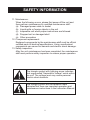
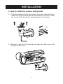
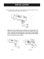
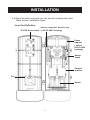
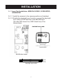
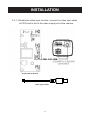
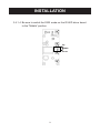
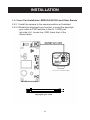
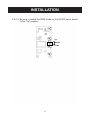
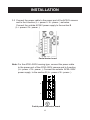
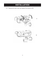
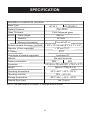
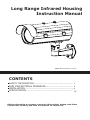
Long Range Infrared Housing
Instruction Manual
ZEIM-4000224G A.5 070
CONTENTS
SAFETY INFORMATION..................................................... 1
PART DESCRIPTION & DIMENSION..................................... 3
INSTALLATION.................................................................. 4
SPECIFICATION................................................................ 15
Before attempting to connect or operate this product, please read these
instructions carefully and save this manual for future use.
SAFETY INFORMATION
Safety Information:
1. Read this Instruction Manual:
Before using the product, please carefully read through the
safety information and operation instructions.
2. Keep this Instruction Manual:
Safely store the Instruction Manual for future reference.
3. Follow instructions:
When operating the unit, please follow instructions on the
Instruction Manual.
4. Cleaning:
Before cleaning the unit, please first unplug the power.
5. Peripheral/accessories:
Do not place the unit on an unstable cart, tripod, or on a
tabletop as personal injury and damage to the unit may occur
due to a fall. Please use officially certified support, frames, and
accessories included with the product. Follow the instructions in
this Instruction Manual during installation to ensure the quality
and maintain safety.
6. Power:
Please follow the labeled specifications on the unit and
supply with the correct power. If unsure of the actual power
requirements, please contact the distributor and do not connect
the power at will.
7. Power cable:
The power cable must be properly secured as improper
connections may cause a short circuit, fire hazards, or serious
damage and hazards.
8. Lightning strike:
During prolonged inactivity, please unplug the power cable and
the video cable to avoid damage from lightning strike and power
surges.
9. Foreign objects and fluids:
Please do not insert any objects into the unit or spill liquids to
avoid short circuits.
10. Warning:
High voltage circuitry contained within the unit. Do not
disassemble to avoid electric shock. All maintenance operations
must be handled by qualified maintenance staff.
SAFETY INFORMATION
11. Maintenance:
When the following occurs, please first power off the unit and
then perform maintenance by qualified maintenance staff:
(a). Damaged power cable or socket
(b). Liquid spills or foreign objects in the unit
(c). Inoperable unit when proper instructions are followed
(d). Dropped unit or damaged shell
(e). Other anomalies
12. Component replacement:
Replaced components by the maintenance staff must be official
certified parts of identical specifications. Using unauthorized
components can cause fire hazards and electric shock damage.
13. Safety inspection:
After the unit maintenance has been completed, the maintenance
staff must perform safety inspection to ensure proper operation.
The triangle symbol with lightning arrow indicates
that ungrounded “Hazardous Voltage” exists within
the unit. The voltage level may cause personal
electric shock hazards.
The triangle symbol with exclamation mark
indicates that there are important operation and
maintenance instructions in the Instruction Manual.
PART DESCRIPTION & DIMENSION
1. Structure Illustration:
The figure above is the illustration of the housing, which may be used
with most of ICR real Day and Night cameras.
2. Dimension and Accessory
Accessory Pack
(1) Video sync cable
(2) Day/night sync cable
(3) Camera power cable
(4) BNC connector
(5) 3 Glands
(6) Hexagon screw driver
(7) Spacer
(8) 2 Screws (for tripod stand)
(9) User manual
INSTALLATION
3. How to install the camera and bracket:
3.1 Take the bracket from the box and put the power cable and video
cable through the bracket then fix the bracket to the wall. (Loose
the screws of the bracket for easy assembly if necessary.)
3.2 Secondly, take out the housing and open the side cover with
hexagon screw driver.
INSTALLATION
3.3 Put the power cable and video cable through the bottom of the
housing and let them pass from the hole.
Attention: Two solutions are available for waterproof: (1)
User can take out the spacer from the accessory pack and
stick it right by the outlet (Fig A) or (2) use the three glands
cover and let the power cable and video cable pass through
the hole of glands cover (Fig B).
Fig. A
Fig. B
INSTALLATION
3.4 Open the side cover and you can see the housing inner part.
There are two installation types.
Inner Part Definition
power connector board (only
IR LED driver board in AC90~260V housing)
Power
Adpator
( only in
AC90~260V
housing)
Heater
board
Camera
position
Fan
Heater
INSTALLATION
3.4.1 Inner Part Installation: MESSOA SCB261, SCB265PRO,
SCB282PRO
3.4.1.1 Install the camera to the camera position as illustrated.
3.4.1.2 Enable the day/night sync funciton: connect the day/night
sync cable to P203 and the to the BW/GND port
(pin side; BW: brown line, GND: black line) of the
camera back.
IR LED driver board
BROWN
BLACK
day/night sync cable
INSTALLATION
3.4.1.3 Enable the video sync funciton: connect the video sync cable
to P202 and to the to the video output port of the camera.
IR LED driver board
video sync cable
INSTALLATION
3.4.1.4 Be sure to switch the S203 mode on the IR LED driver board
to the "Middle" position.
Up
Middle
Down
INSTALLATION
3.4.2 Inner Part Installation: MESSOA NIC836i and Other Brands
3.4.2.1 Install the camera to the camera position as illustrated.
3.4.2.2 Enable the day/night sync funciton: connect the day/night
sync cable to P203 and the to the AL. I./GND port
(pin side; AL.I: brown line, GND: black line) of the
camera back.
IR LED driver board
BROWN
BLACK
day/night sync cable
10
INSTALLATION
3.4.2.3 Be sure to switch the S203 mode on the IR LED driver board
to the "Up" position.
Up
Middle
Down
11
INSTALLATION
3.5 Connect the power cable to the power port of the AC24V camera
and to the A section (L+: power +/ N-: power- ) as below.
Connect the outside AC24V power supply to the section B
(L+: power+/ N-: power- ).
Partial heater board
Note: For the AC90~260V housing type, connect the power cable
to the power port of the AC90~260V camera and to A section
(L+: power +/ N-: power- ). Connect the outside AC90~260V
power supply to the section B (L+: power+/ N-: power- ).
B.
A.
Partial power connector board
12
INSTALLATION
3.6 Then, close the side cover and use the provided screws to fix
the housing on the bracket with hexagon screw driver.
3.7 Loosen the pan and tilt adjustment screw of the bracket to
modify the angle of the housing and then tighten the screw.
13
INSTALLATION
3.8 Replace the side cover and tighten the screws (A/ B).
A
B
14
SPECIFICATION
INFRARED ILLUMINATOR HOUSING
INFRARED
Model No ILLUMINATOR HOUSING
SLI070HB-2
Model
Power Type
Input Voltage
SLI070HB-7
AC 24 V
Radiant Distance
AC 90-260 V
70 m(230ft)
70M
(230ft)
Glass Thickness
6 mm tempered glass
IR LED
Wave Length
850 nm
Quantity
96 Units
Minimum illumination
IR
on with
0 luxIR on
0 lux
x 70 xthan
90 mm
(8.3" x 2.7"
Suitable camera dimension (HxDxW) < 210 Less
210x70x90
mm x 3.5")
< 45than
mm45mm
(1.8")
Diameter of lens suggested
Less
IP
67
IP66
IP Rating
View angle of camera suggested
Less than 50°
Material
Power consumption
Dimension
Die-cast aluminum
35W
40W
174173
x 422
145xmm
(6.9"xx154
16.6"
x 5.7")
mmx(W)
450(D)
mm
(H)
Approx
Approx3.75kg
3500 g(8.3 lb)
Weight
o
o
-30°C~50C°
-30 C(-22°F~122°F)
~ 50 C
Operating temperature
Operating humidity 30% ~ 90% RH
o
Storage temperature o
-40 C(-40°F~140°F)
~ 60 C
-40°C~60C°
Camera Sync Input Yes (V-sync)
NOTE:The specification is subject to change without notice.
15