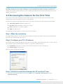
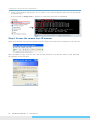
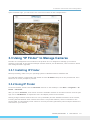
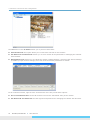
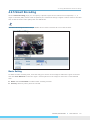
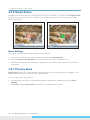
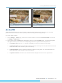
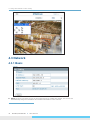
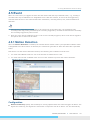
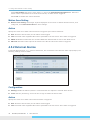
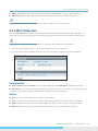
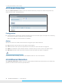
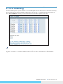
1
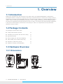
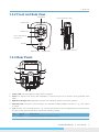
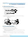
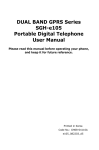
www.messoa.com 1080p Cube Network Camera NCC800/NCC800WL User Manual 5300-00000001-21Y A1 Safety Notice The camera is intended for indoor use. Make sure the supplied voltage meets the power consumption requirements of the camera before powering the camera on. Incorrect voltage may cause damage to the camera. The camera should be protected from water and moisture, excessive heat, direct sunlight and cold. The installation should be made by a qualified service person and should conform to all local codes. Unplug the camera during lightning storms or when unused for long period of time. NCC800/NCC800WL l User Manual 1 Table of Contents Table of Contents Safety Notice........................................................................................................ 1 1. Overview................................................................................................. 4 1.1 Introduction..................................................................................................... 4 1.2 Package Contents............................................................................................. 4 1.3 Hardware Overview........................................................................................... 4 1.3.1 Dimensions.......................................................................................................... 4 1.3.2 Front and Side View.............................................................................................. 5 1.3.3 Rear Panel........................................................................................................... 5 1.4 Specifications................................................................................................... 7 2. Camera Installation................................................................................. 8 2.1 Mounting the Camera........................................................................................ 8 2.2 Connecting the Cables....................................................................................... 8 2.3 Adjusting the Focus.......................................................................................... 9 3. Network Connection and Configuration................................................... 10 3.1 Network Connection Types............................................................................... 10 3.3 Using “IP Finder” to Manage Cameras................................................................ 15 3.3.1 Installing IP Finder...............................................................................................15 3.3.2 Using IP Finder....................................................................................................15 4. Using Web-based Control Utility............................................................. 18 4.1 Overview....................................................................................................... 18 4.1.1 Main Screen........................................................................................................18 4.1.2 Setup Menu........................................................................................................19 4.1.3 Applying Settings.................................................................................................19 4.2 Image Settings.............................................................................................. 20 4.2.1 Codec ...............................................................................................................20 4.2.2 Exposure............................................................................................................23 4.2.3 White Balance.....................................................................................................25 4.2.4 Basic Setting.......................................................................................................26 4.2.5 Smart Encoding...................................................................................................27 4.2.6 Smart Focus........................................................................................................28 4.2.7 Privacy Zone.......................................................................................................28 4.2.8 ePTZ..................................................................................................................29 4.3 Network........................................................................................................ 30 4.3.1 Basic..................................................................................................................30 2 NCC800/NCC800WL l User Manual Table of Contents 4.3.2 WLAN.................................................................................................................31 4.3.3 FTP....................................................................................................................33 4.3.4 SMTP.................................................................................................................34 4.3.5 NTP...................................................................................................................34 4.3.6 RTSP..................................................................................................................35 4.3.7 ONVIF................................................................................................................35 4.4 System......................................................................................................... 37 4.4.1 Date and Time.....................................................................................................37 4.4.2 Time Stamp........................................................................................................38 4.4.3 Firmware............................................................................................................38 4.4.4 User Management................................................................................................40 4.4.5 Language . .........................................................................................................40 4.4.6 Log....................................................................................................................41 4.4.7 Audio.................................................................................................................42 4.5 Event............................................................................................................ 43 4.5.1 Motion Detection..................................................................................................43 4.5.2 External Alarms...................................................................................................44 4.5.4 Blur Detection.....................................................................................................45 4.5.5 Audio Detection...................................................................................................46 4.5.6 Ethernet Detection...............................................................................................46 4.5.7 Event Management...............................................................................................47 4.6 Recording...................................................................................................... 48 4.6.1 Settings – Video File.............................................................................................48 4.6.2 Settings – FTP.....................................................................................................48 4.6.3 Settings – SMTP..................................................................................................49 4.6.4 SD Card Storage Format Selection..........................................................................50 4.6.5 Period Setting.....................................................................................................51 NCC800/NCC800WL l User Manual 3 1. Overview 1. Overview 1.1 Introduction Featuring 2-megapixel Full HD resolution at full frame rates, the NCC800/NCC800WL is designed for professional indoor surveillance, targeting retail shops, small businesses or offices where image quality is emphasized. The built-in infrared LED gives true, maximized night visibility in complete darkness up to 10 meters. Further enhanced by MESSOA’s proprietary Lumii™ imaging technology, the NCC800/NCC800WL provides the unparalleled low light performance like no others. The camera also offers flexible installation, 2-way audio communication, and wireless connectivity to make it a comprehensive and professional business security solution. 1.2 Package Contents The package includes these items: 1080p Cube Network Camera x1 CD-ROM (User manual and IP Finder utility) x1 Quick Start Guide x1 Power Supply (DC 12V Power Adaptor) x1 Video Cable (2-Pin to BNC Video Out) x1 Bracket for wall/ceiling mount x1 USB Wi-Fi Dongle (for NCC800WL) x1 1.3 Hardware Overview 1.3.1 Dimensions 42mm (1.66”) 76mm (2.98”) 79mm (3.10”) 99mm (3.92”) 4 NCC800/NCC800WL l User Manual 90mm (3.56”) 92mm (3.62”) 78mm (3.08”) 103mm (4.06”) 33mm (1.31”) 24mm (0.94”) 73mm (2.88”) 1. Overview 1.3.2 Front and Side View Microphone Focus Adjustment Ring Infrared LED Camera Lens Focus Adjustment Ring Screw Speaker Ethernet LED microSD/SDHC card slot Wireless LED 1.3.3 Rear Panel ALM-In + ALM-In ALM-Out GND Reset 4 3 2 1 DC 12V 1. Power LED: The LED lights on when power is applied. 2. Video: To adjust focus during the installation, connect this port to a monitor using provided video cable. 3. USB Wi-Fi Dongle slot: Optionally connect to a USB Wi-Fi dongle for wireless function. 4. Ethernet/PoE: Connects to the LAN port of a standard 10Base/100Base-TX device, e.g., hub, switch or router. 5. I/O: Connect your external devices, e.g., sensor and alarms to the corresponding I/O terminal block. The pins of the I/O terminal block controls the following signals: Pin Signal Connection 1 GND Ground (electricity) in electrical circuits. NCC800/NCC800WL l User Manual 5 1. Overview 2 ALM-Out Connect to device that responds to alarm signals. The camera uses an NMOS transistor with source connected to GND. If used with an external relay, a diode must be connected in parallel with the load to protect against transient voltages. 3 ALM-IN - Connect to device that triggers alarm signals. Connect to external power source negative side (0V) to activate. 4 ALM-IN + Connect to device that triggers alarm signals. Connect to external power source positive side (3.3V~5V) to activate. 6. DC 12V: Connect to the provided power adapter. If you are to use power from Ethernet connection, this connector is not used. 7. Audio In: Connect to a microphone 8. Audio Out: Connect to a speaker. 9. Reset: Using a pointed object, hold down the reset button for about 5 seconds to restart the camera. Or hold down the reset button for longer than 5 seconds to reset the camera to the factory defaults. 10.MAC address: The MAC (Media Access Control) address of the camera's Ethernet interface is displayed on the camera's label. If your camera comes with a wireless dongle, then the MAC address is displayed on the dongle's label. 6 NCC800/NCC800WL l User Manual 1. Overview 1.4 Specifications Image System Image Sensor 1/2.7" 2MP HD image sensor optimized for low-light performance Image Compression Triple Streaming : H.264 / MPEG4 / Motion JPEG Maximum Framerate 30 fps (NTSC) and 25 fps (PAL) in 2MP Full HD 1080p (1920x1080) Lens Built-in fixed lens f=3.1 mm, F=2.0(Mega pixel lens) View Angle H: 77° ±5%; V: 57° ±5% Terminal block x1 In / x1 Out Audio In / Out 3.5mm Phone Jack 1 In / 1 out Power DC 12V Video Video out x1, 2-pin to BNC video out LAN RJ-45 x1, 10/100Mbps; 10Base-T/100Base-TX USB USB port x1, for connection to USB Wi-Fi dongle Reset Within 5 sec for rebooting system; more than 5 sec for loading default Memory Card microSD/SDHC card slot Mechanism Electric Shutter Time Alarm Port Range from 1/10000s to 1/3.75s selectable (60Hz); Range from 1/10000s to 1/3.125s selectable (50Hz) Dimensions(WxHxD) (without bracket) 76mm x 103mm x42mm (2.98”x4.06”x 1.66”) Weight 118g (Without Bracket) . Audio Two-way build in MIC & Speaker; Mono Audio, Full-duplex, G.711 PCM 8kHz Alarm External input Power Supply DC 12V Power adaptor Day/Night Mode D/N control: Auto Mode Video Cable 2-Pin to BNC Video Out cable Minimum Illumination IR LED OFF: 0.2lux@10IRE / 1.1lux@50IRE (F2.0, 1/15s) IR LED ON: 0 Lux Bracket Wall mount, ceiling mount Document Quick Installation Guide CD-ROM User Manual, Quick Installation Guide, IP Finder Utility Other USB Wi-Fi Dongle (for NCC800WL) IR LED IR Distance IR LED 9 pcs(850nm) 10M (33ft) IR Turn On Status Under 10 Lux by auto control LED Life More than 10,000 hours (50ºC) Video Port 2 pin connector, 1.25mm wafer, 1.0Vp-p, 75Ω Video Output NTSC: 720 X 480 @30fps; PAL: 720 X 576 @25fps RTC Real-Time clock calendar Image Enhance Exposure Mode: Auto/Manual White Balance: Auto/Manual Backlight Compensation: 5x5 zones selectable Sharpness, Staturation, Brightness, Contrast: 255 level sensitivity Package Contents Feature Brief Digital WDR Yes; 5-level sensitivity Privacy Zone Yes; customized threshold privacy zone Intelligent Video Audio Detection/ Blur Detection/ Ethernet Detection/ Smart Encoding/ Smart Focus/ e-PTZ/ Event Management Alarm Detection Motion Detection: 5 x 5 zones, 5-level sensitivity or customized threshold Audio Detection: 5 level sensitivity or customized threshold Blur Detection: customized threshold External Input Alarm Event File upload via FTP, SMTP and SD Card Notification via email, HTTP and TCP External output activation Video and audio recording to SD Card Image Orientation Mirror, Flip Bit Rate Mode Primary stream bit rate control: CBR/VBR Local Storage Memory Card microSD/SDHC Card up to 32 GB SD Card Overwrite Yes Store Category Alarm / Motion / Schedule/ Un-interrupt recording Power Supply Power Requirement DC 12V ± 10% / PoE (IEEE 802.3af) Power Connector DC Jack (2.0mm) Power Consumption(Max) NCC800: 7W, NCC800WL:7.5W LED Indicator x1 Power LED (Red) Environment Operating Temperature -10ºC ~ 50ºC (-14ºF ~ 122 ºF) Operating Humidity 10~ 90% RH Storage Temperature -20ºC ~ 60ºC (-4ºF ~ 140 ºF) Regulatory CE, FCC (class B), RoHS Network Ethernet 10/100Mbps; 10Base-T/100Base-TX Ethernet connection for LAN / WAN, RJ-45 Wireless USB Wi-Fi Dongle (Optional); IEEE 802.11b/g/n LED Indicator x2 network LED(Green & Yellow) Internet Protocol IPv4, TCP/IP, UDP, HTTP, SMTP, DNS, DHCP, NTP, SSH, FTP, RTP,RTSP, ICMP, UPnP Browser IE browser 6.0 or above I/O Connector NCC800/NCC800WL l User Manual 7 2. Camera Installation 2. Camera Installation 2.1 Mounting the Camera 1. Drill three holes at the desired location and insert provided anchors into the holes. Then fasten the provided screws into the anchors to secure the camera to the wall. 2. To adjust the camera angle, use a torx key to loosen the two screws and loosen the knob. After adjustment is done, fasten the screws and the knob. Loosen the two screws and the and knob. 2.2 Connecting the Cables 1. Optionally connect alarm input/output devices to the camera. 2. Optionally connect a speaker and microphone to the camera. 3. Connect the camera to a power source, using one of these options: • DC 12V: Connect to the provided power adapter. • PoE: Using an Ethernet cable, connect the LAN port to a PoE-capable network device. Power will be supplied through the Ethernet cable. 4. Optionally connect a video monitor if you want to perform focus and iris adjustments during the installation. 5. For NCC800WL, connect the USB Wi-Fi dongle to the USB port of the camera for wireless capability. 8 NCC800/NCC800WL l User Manual 2. Camera Installation 2.3 Adjusting the Focus Loosen the Focus Adjustment Ring screw first and then rotate the ring to adjust the focus. After adjustment, fasten the screw. NCC800/NCC800WL l User Manual 9 3. Network Connection and Configuration 3. Network Connection and Configuration 3.1 Network Connection Types There are many different ways that you can connect the camera to your network, depending on your applications requirements. You should always set the camera’s network settings according to your network configurations. The following diagrams depict some typical applications with guidelines on network settings. For more information on network settings, always consult with your network administrator or ISP as required. Type 1: Direct Connection to a PC Directly connect the camera to a PC using a standard Ethernet cable. To extend the connection length, you should use a RJ-45 female/female coupler to connect two Ethernet cables together. RJ-45 Coupler Caution Tip Note The LAN port of the camera supports auto MDI/MDIX (Medium dependent interface crossover) so there is no need to use cross-over cable. To access the camera, the PC must be on the same network as the camera. The default IP address of the camera is a static one (192.168.1.30). Configure your PC’s IP address as 192.168.1. X (where X is a number between 2 to 254, excluding 30 and subnet mask as 255.255.255.0, and then your PC should be able to access the camera. Type 2: Connecting Camera(s) to a Local Area Network (LAN) To add the camera(s) to an existing LAN, just connect the camera(s) to the hub or switch on your network. If you want to provide the camera power via the Ethernet connection, a PoE-enabled hub/switch is required. 10 NCC800/NCC800WL l User Manual 3. Network Connection and Configuration Caution Tip Note The LAN port of the camera supports auto MDI/MDIX (Medium dependent interface crossover) so there is no need for an uplink port or the use of a cross-over cable. Assign an IP address to your camera following your network IP allocation policy. You can manually specify the IP address or allocate the IP address automatically using a DHCP server, if available on your network. Then, you can monitor and mange the camera via a web browser from a local PC. Router/Switch/Hub Type 3: Connecting Camera(s) to a Wireless Network If you connect an optional USB Wi-Fi dongle to the camera, then the camera can also connect to a wireless network in either of the following ways: Ad-Hoc Mode This is a peer-to-peer connection type where your camera directly connect to another wireless device. Each wireless devices on the network share the same SSID. The access the camera, the wireless node, e.g., your wireless PC, must meet these requirements: Must be on the same network as the camera. The default IP address of the camera is a static one (192.168.1.30). So you need to configure your wireless PC’s IP address as 192.168.1. X (where X is a number between 2 to 254, excluding 30 and subnet mask as 255.255.255.0. Must use the same SSID and channel number as the camera. NCC800/NCC800WL l User Manual 11 3. Network Connection and Configuration Infrastructure Mode Using the Infrastructure network type, the camera will use an AP (Access Point) as an intermediary to link to the wireless network and the wired LAN. For wireless connectivity, all the wireless deivces on the same wireless network must use the same SSID. Typically the Access Point will also work as a router and has built-in DHCP function to assign a local IP address to your camera. You can alternatively assign a fixed IP address to the camera to prevent it from frequently changing. Under the Infrastructure mode, you can access the camera in either of these ways: From a wired PC: Any PC on the same network should be able to access the camera. From a wireless device: The wireless device must use the same SSID and channel number as the camera and must be on the same network as the camera. Access Point Type 4: Remote Connection via the Internet If the network where the camera resides is connected to the Internet, you can also provide remote access to your camera over the Internet. Typically a broadband router has a built-in DHCP function to assign a local IP address to your camera. You can alternatively assign a fixed IP address to the camera to prevent it from frequently changing. Router xDSL/Cable Modem To access the camera from a local PC, simply use the local IP address of the camera. 12 NCC800/NCC800WL l User Manual 3. Network Connection and Configuration To enable remote access, you must configure your router/firewall to forward an incoming request to that fixed local IP address of the camera. Therefore, when an external host sends a request to access your camera, the request will first reach the router’s external IP address and then be forwarded to the local IP address of the camera. 3.2 Accessing the Camera for the First Time The camera comes with a web-based setup utility, allowing you to view the video of the camera and configure the camera for optimal use in your environment. To access the camera’s web-based control utility, you need a PC that meets the following requirements: Operating System: Windows Vista® or XP Browser: Internet Explorer Version 6.0 or later CPU: Intel Pentium 4.2 GHz or higher RAM: 512 MB or more Then take the following steps to connect your PC to the camera. Step 1: Make the connection For initial setup purposes, connect one end of an Ethernet cable to the RJ45 connector of the camera and the other end to the LAN port on your PC. Step 2: Configure your PC’s IP address The camera uses a default IP address of 192.168.1.30 and subnet mask of 255.255.255.0. To have your PC on the same network with the camera, configure your PC’s IP settings as below: IP address: 192.168.1. X, where X is a number between 2 to 254, excluding 30. Subnet mask: 255.255.255.0. Ignore all other settings and click OK. Step 3: Verify the connection between the PC and the IP Cam 6. Launch the Command Prompt by clicking the Start menu, Programs, Accessories and then Command Prompt. NCC800/NCC800WL l User Manual 13 3. Network Connection and Configuration 7. At the prompt window, type ping x.x.x.x, where x.x.x.x is the IP address of the camera (the default is 192.168.1.30). If the message of “Reply from…” appears, it means the connection is established. Step 4: Access the camera from IE browser Open the IE browser and enter the IP address of the camera in the URL field. The default is 192.168.1.30. When prompted to login, enter the user name and the password. (The defaults: admin, 1234). Note that the password is case-sensitive. 14 NCC800/NCC800WL l User Manual 3. Network Connection and Configuration Upon successful login, you will see the live view screen shown as the example below: 3.3 Using “IP Finder” to Manage Cameras IP Finder is a management tool included on the product CD. It is designed to manage your network cameras on the LAN. It can help find multiple network cameras, set IP addresses, show connection status and manage firmware upgrades. 3.3.1 Installing IP Finder Before proceeding, make sure your operating system is Windows Vista or Windows XP. To install the software, simple locate and double-click the IP Finder setup file on the provided CD. Then follow the on-screen prompts to proceed. 3.3.2 Using IP Finder To launch IP Finder, double-click the IP Finder shortcut on the desktop or click Start > Programs > IP Finder > IP Finder. After you launch IP Finder, it will search for all the available cameras on the same network. Click the plus sign next to “All Devices” to expand the menu and display all the found cameras. Clicking a target camera will show the live view (if available) and the detailed information of the camera, including the MAC address. Each camera comes with a unique MAC address, which is indicated on the product label. It helps identify which camera is currently accessed, particularly when multiple cameras are connected on your network. NCC800/NCC800WL l User Manual 15 3. Network Connection and Configuration The Tool menu of the IP Finder allows you to perform these tasks: Search Network: This option allows you to search the cameras on the network. Set Master ID and Password: Allows you to set a master ID and password for managing the cameras with IP Finder. Management Tool: Allows you to restart the camera, update firmware, reset all of the camera settings to default (except network settings) and reset all of the camera parameters to default. For an individual camera, right-click the camera and a menu will provide these options: Go to Presentation URL: Launch IE browser to access the web-based utility of the camera. Set Device ID and Password: Set the login ID and password for managing the camera with IP Finder. 16 NCC800/NCC800WL l User Manual 3. Network Connection and Configuration Network Information: Allows you to configure the camera’s network settings. NCC800/NCC800WL l User Manual 17 4. Using Web-based Control Utility 4. Using Web-based Control Utility 4.1 Overview 4.1.1 Main Screen After you login to the camera’s web-based control utility, you will first see the live view screen of the camera. The screen is like the picture below: Live view video Snapshot button Camera name Setup button Alarm Indicator Recording Indicator The live view screen of the utility provides these options: Snapshot: Pressing this button takes a snapshot of the current live view screen. Live: Pressing this button displays the live view of the camera. Setup: Pressing this button allows you to access the setup page. Camera name: Displays the name of the camera. Recording Indicator: Turns red when the recording is proceeding. Alarm Indicator: Appears when an alarm is triggered. Live view video: Shows the live view of the camera. Note that the accessibility to the options varies according to the login account. 18 NCC800/NCC800WL l User Manual 4. Using Web-based Control Utility Viewer: Allowed to view only the live view screen. Access to other options is restricted. Administrator: Can access all the options on the live view page and make configurations on the setup pages. 4.1.2 Setup Menu The Setup options are categorized into five groups: Image, Network, System, Event and Recording. Clicking the name will expand its sub-menu. See the ensuing sections for more information. 4.1.3 Applying Settings Each configuration page provides a Save button. Settings are applied right after you press the Save button. And the browser will refresh to load the latest setting or otherwise pop up the “Save OK” message to indicate that settings have been applied. NCC800/NCC800WL l User Manual 19 4. Using Web-based Control Utility 4.2 Image Settings 4.2.1 Codec The Codec page allows you to configure the video streams for the camera. You can optionally configure a secondary or third stream to a resolution as required by your third-party device or software. Camera Name Settings Enter a descriptive name of the camera. Note that if you want to make the camera ONVIF compliant (see Network > ONVIF ), no space is allowed in the camera name. 20 NCC800/NCC800WL l User Manual 4. Using Web-based Control Utility Stream Settings Stream setting optinos vary according to the codec. Selectable codec for each streaming also depend on the codec of the other two streams as described in the table below: Streaming Combination Primary Codec Resolution 1080P MJPEG H264 MPEG4 Secondary Codec Resolution OFF N/A H264 MPEG4 D1 VGA 2CIF CIF SXVGA 720P XGA SVGA D1 OFF N/A H264 MPEG4 D1 VGA 2CIF CIF 1080P OFF N/A SXVGA 720P XGA SVGA D1 OFF N/A H264 MPEG4 D1 VGA 2CIF CIF Third Codec Resolution OFF N/A OFF N/A MJPEG VGA CIF OFF N/A MJPEG VGA CIF OFF N/A MJPEG VGA CIF OFF N/A MJPEG VGA CIF OFF N/A MJPEG VGA CIF H.264 Codec Settings Resolution: Choose a resolution for the video. Choices include 1080p, SXVGA, 720p, XGA, SVGA, D1, VGA, 2CIF and CIF, depending on the codec of the other two streams. Bit Rate: According to your bandwidth, specify a value for data transmission rate (kbps). Higher value gets higher video quality but consumes more bandwidth. Frame Rate: Choose the intended frame rate, i.e., the number of frames to transmit per second. I-Frame Interval: This setting allows you to specify the intervals between I-Frames (Intra Frame) to optimize your bandwidth and storage space consumption. An I-Frame is the first image in a video sequence and it contains entire image information. Frames that follow I-Frame, P-Frames, carry only the necessary changes as compared to I-Frame, so they are smaller in file size. When intervals between I-Frames are longer, the less I-Frames are needed and thus consuming less bandwidth and storage space. Recommended settings are as below: • Longer I-Frame interval: For normal scenes where there is less motion and sufficient lighting. • Shorter I-Frame interval: For scenes with lots of motion, or under poor lighting conditions. NCC800/NCC800WL l User Manual 21 4. Using Web-based Control Utility MPEG4 Codec Setting Resolution: Choose a resolution for the video. Choices include 1080p, SXVGA, 720p, XGA, SVGA, D1, VGA, 2CIF and CIF, depending on the codec of the other two streams. Bit Rate: According to your bandwidth, specify a value for data transmission rate (kbps). Higher value gets higher video quality but consumes more bandwidth. Frame Rate: Choose the intended frame rate, i.e., the number of frames to transmit per second. I-Frame Interval: This setting allows you to specify the intervals between I-Frames (Intra Frame). An I-Frame is the first image in a video sequence and it contains entire image information. Frames that follow I-Frame carry only the necessary changes as compared to I-Frame and thus reducing the amount of data needed to transmit the video. Generally when intervals between I-Frames are longer, the less I-Frames are needed and thus consuming less bandwidth, but the video quality is lower. MJPEG Codec Settings Resolution: Choose a resolution for the video. Choices include 1080p, SXVGA, 720p, XGA, SVGA, D1, VGA, 2CIF and CIF, depending on the codec of the other two streams. Quality: Set the image’s quality as High, Normal or Low. Frame Rate: Choose the intended frame rate, i.e., the number of frames to transmit per second. Caution Tip Note 1. Live View uses the MJPEG codec. If no streaming is using MJPEG, it will result in no video for Live View. 2. If MJPEG is selected for both the primary stream and the third stream, Live View will always display video using the third stream codec settings. Mirror Settings This option allows you to mirror or flip the video image if required. OFF: Turns off this function. HORIZONTAL: Flips the images horizontally. VERTICAL: Flips the images vertically. BOTH: Flips the images vertically and horizontally. Rate Control Choose a bit rate control to manage your bandwidth usage. Variable Bit Rate (VBR): VBR keeps the video stream quality as constant as possible by varying bit rate. This mode ensures high quality image for motion scene and is often selected when image quality demands priority. However, this mode requires more bandwidth in order to vary the bit rate. Constant Bit Rate (CBR): CBR maintains a specific and constant bit rate by varying the stream quality. With CBR, streaming is smooth and network throughput is stable for any scene. This mode is typically used with a limited bandwidth environment. 22 NCC800/NCC800WL l User Manual 4. Using Web-based Control Utility TV Output Stream Turn on this option if you connect an analog monitor to the camera’s Video connector for video output. 4.2.2 Exposure The Exposure page allows you to configure the Exposure Mode and Backlight Compensation settings according to the light conditions of the camera. Exposure Mode Auto Exposure Settings Method: Select which area of the image will be used to measure the amount of light to achieve best exposure. • Center Weighted: Exposure metering is averaged over the entire frame but emphasis is placed on the central area. • Object Targeted: This option meters the exposure based on the targets you specify. When this option is selected, define your target by clicking squares displayed on the image and then press Save Spot Window to save the setting. EV: In a scene with predominantly light or dark areas, the image will be underexposed or overexposed, causing an image to be too dark or bright. In such situations, you can adjust a compensation value to optimize the exposure. Decrease the value if images appear too light (overexposed). Increase the value if images are too dark (underexposed). Max/Min. Exp: Select the maximum / minimum exposure time according to the light source. The selectable value will change according to the frequency setting under Image > Basic Settings. Sensitivity: Select how sensitive the camera reacts to the light. A higher value enables the camera to be more sensitive to the light conditions and adjust the exposure in the shortest time interval. Max Gain: Specify the maximum amount of amplification applied to the image. A high level of gain allows images to be viewable in very low light, but will increase the image noise. Manual Exposure Settings Exposure Time: Enter a desired exposure time. NCC800/NCC800WL l User Manual 23 4. Using Web-based Control Utility Gain: Select a gain value from 0 to 16. A high level of gain allows images to be viewable in very low light, but will increase image noise. BLC (Backlight Compensation) The Backlight Compensation function allows you to provide the optimal exposure of subjects under back light circumstances. OFF/ON: Choose to enable or disable the BLC function. BLC area setting: BLC area refers to the dark area where more details are expected. Define your BLC area by clicking squares displayed on the screen and then press Save BLC Window to save the setting. Digital Wide Dynamic Range When there are both very bright and very dark areas simultaneously in the field of view, you can enable Digital Wide Dynamic Range (WDR) function. It optimizes an image to ensure that dark areas are more visible while retaining details in bright areas. Level: Depending on the contrast/dynamic range of a scene, you can select different level of WDR. Higher level of WDR suits for higher contrast/dynamic scene. If you select Auto mode, the camera will automatically adjust the WDR level by itself depending on the light of the scene. 24 NCC800/NCC800WL l User Manual 4. Using Web-based Control Utility 4.2.3 White Balance Select a white balance mode according to external light condition for the best color temperature. Auto White Balance: Use this option when there is no special lighting in the environment. The camera will automatically adjust the color temperature according to the light conditions and the sensitivity you specify. The higher the sensitivity, the faster the adjustment. If the lighting conditions change frequently, select a lower sensitivity to prevent the camera from frequently changing white balance. Manual White Balance: With any special light in the environment, you can use this option to manually adjust the red, green and blue channels, which are mostly affected by the special light. For example, if red color is too bright, then you should lower the R Gain value. NCC800/NCC800WL l User Manual 25 4. Using Web-based Control Utility 4.2.4 Basic Setting The Basic Setting allows you to specify a frequency and adjust the basic image settings to optimize your video image. Frequency: Select an appropriate frequency to reduce the flicker on the image. “50 Hz” and “60 Hz” are provided Frequencies settings will affect the Max. Exposure and Min. Exposure settings under Image > Exposure. TV System: Displays the current video standard: NTSC or PAL. This setting cannot be changed via web interface. Brightness: Adjust the image brightness level. Contrast: Adjust the image contrast level. Saturation: Adjust the image saturation level. Sharpness: Adjust the image sharpness level. Default All Image parameters: Pressing this button will restore all the image settings to the defaults. 26 NCC800/NCC800WL l User Manual 4. Using Web-based Control Utility 4.2.5 Smart Encoding On the Smart Encoding page you can specify a specific region of the video as more important, i.e., a region of interest (ROI). When a ROI is specified, the camera will assign a higher number of bits to the ROI area to deliver better video quality than non-ROI areas. Caution Tip Note The Smart Encoding function is only available when H.264 is selected for one of the streams. Basic Setting To define a smart encoding area, click and drag your mouse on the image to define the region of interest and click Save Window to save the region. Click anywhere on the image to cancel the current defined area. Mode: Select Fixed ROI to enable smart encoding function. Priority: Select a priority level for the ROI. NCC800/NCC800WL l User Manual 27 4. Using Web-based Control Utility 4.2.6 Smart Focus In addition to observing the live view image to see if focus is achieved, you can also enable Smart Focus to help you verify if focus is locked. If this function is enabled, whenever focus is achieved, the focus window turns green. Basic Settings To focus on a desired subject using the Smart Focus function: 1. Click on the subject that you want to focus on and then click Save Window. 2. Check the Smart Focus Enabled box. This will turn the smart focus indicator to red. 3. Use the focal length and focus controls to optimize the focus. When focus is achieved, the indicator turns green. 4.2.7 Privacy Zone Privacy Zone allows you to mask sensitive areas of the image for privacy protection. If enabled, it will mask the live view and the recorded video clips/JPEG files. To turn on the privacy zone function: 4. Click and drag your mouse on the image to define the region to be masked and then click Save Window. 5. Select ON to enable Privacy Zone. This will turn the masked area to black. 28 NCC800/NCC800WL l User Manual 4. Using Web-based Control Utility 4.2.8 ePTZ Using the ePTZ function, you can use the pan, tilt and zoom controls to steer the camera to a desired position and focus on desired close-up areas, without moving the camera physically. To use the ePTZ function: 1. On the Image > Codec page, make sure the first streams is active and TV Out Stream is turned off on Image > Codec page. 2. On the main screen, a PTZ button will appear. After you click the ePTZ button, an ePTZ control panel will appear where you can click the corresponding indicators to perform desired operations: • To zoom in/out: Click the +/- indicator repeatedly to zoom in/out the live view image. • To pan left/right: Click the left/right indicator to pan the viewing area. The pan function does not work if the video is not zoomed-in (no zoom status). • To tilt up/down: Click the up/down indicator to tilt the viewing area. The tilt function does not work if the video is not zoomed-in (no zoom status). • To preset to home: Click the home indicator and the image will return to the original view. NCC800/NCC800WL l User Manual 29 4. Using Web-based Control Utility 4.3 Network 4.3.1 Basic DHCP: If there is a DHCP server on the network and you enable this option, the server will automatically assign an IP address and related information to the camera. 30 NCC800/NCC800WL l User Manual 4. Using Web-based Control Utility Caution Tip Note If there is no DHCP server on your network or you prefer to manually assign an IP address to the camera, leave the DHCP checkbox blank. IP Address & Subnet Mask: If the DHCP function is not enabled, you have to assign an IP address with the subnet mask to the camera. Default Gateway: Enter the IP address of the gateway if required. Please contact your network administrator whether you need to set up the gateway. DNS: Enter the IP address of a DNS server. If you enter a domain name instead of an IP address in server-related fields, e.g., FTP, SMTP or NTP server, then the camera will need a DNS server to translate domain names into an IP address that is actually used for communication on the Internet. HTTP Port: Use the standard HTTP port number 80 or alternatively specify another port number between 1025 and 65535. If you choose to use a non-standard port, and the camera on the LAN is to be accessible from the Internet, then you must configure your router/firewall to forward incoming HTTP request to that specified port (via NAPT/port forwarding settings). MAC: Display the MAC address of the camera. Each camera comes with a unique MAC address, which is indicated on the product label. It helps you to identify which camera is currently accessed, particularly when multiple cameras are connected to your network. 4.3.2 WLAN If the camera is inserted with a USB Wi-Fi dongle, then a WLAN page will appear for you to configure wireless settings. Basic Settings Site Survey: Clicking the Scan button allows you to search for wireless networks available in the air. After scanning, available wireless networks will appear in the drop-down list. You can select one from the list to see related Access Point (AP) information, including signal strength, BSSID (the MAC address of the wireless interface) and wirless mode. NCC800/NCC800WL l User Manual 31 g 4. Using Web-based Control Utility If you select a wireless network from the Site Survey list, then required fields will appear and some fields will be filled automatically. If you don’t want to use the sites scanned by the camera, then you need to manually enter the following required information. SSID: Enter the name of the wireless network your camera is going to connect to. Network Type: Specify the network type of the wireless network the camera is to connect to. Usually “Infrastructure” is used if you want to connect to a network through an intermediary Access Point. If you want to directly connect to another wireless device, then choose “Ad-hoc” mode. Channel: If your wireless network type is “Infrastructure”, then simply select “Auto”. If your wireless network type is “Ad-hoc”, then you must select the channel used by the wireless devices. All the wireless devices in an Ad-hoc network must use the same channel for wireless communication. Authentication: Select the authentication used by your wireless network. Options include Open, Shared, WPA-Personal and WPA2-Personal. Encryption: Select an encryption method used by the wireless network your camera is going to connect to. Available options, WEP, AES or TKIP, depend on the authentication type. Authentication Encryption Key Open None NONE WEP WEP keys Shared WEP WEP keys WPA-Personal TKIP, AES Shared key WPA2-Personal AES Shared key WEP key: If you use WEP as the encryption method, select characters or hexadecimal digits as the key format and then enter up to four keys. When using hexadecimal format, only digits 0-9 and letters a-f, A-F are allowed. Make sure the WEP keys match the required key format and length as below: Caution Tip Key Characters Hexadecimal digits 64-Bit 5 alphanumeric characters 10 hexadecimal digits 128-Bit 13 alphanumeric characters 26 hexadecimal digits Note When setting WEP keys for data encryption, make sure to use the same encryption key values in identical order as used by the target wireless network. Shared key: If you use AES or TKIP as the encryption method, enter the shared key used by your tarket wireless network. Advanced Settings 32 NCC800/NCC800WL l User Manual 4. Using Web-based Control Utility Wireless Mode: Select an appropriate wireless mode according to the modes of the Access Points in your network. Upon your selection, only Access Points that meet the selected specifications will be scanned when using Site Survey function. For example, if you select bg-mixed, only 802.11b and 802.11g Access Points will be scanned. Bandwidth: Select 20 MHz or Auto 20/40 MHz according to your requirement. In addition to legacy channel bandwidth of 20 MHz, the 802.11n specification also allows the use of a 40-MHz wide channel. Using 40-MHz bandwidth may achieve higher data rates but also leads to fewer channels available. 4.3.3 FTP To allow the camera to upload recorded video clips/JPEG files to an FTP server, you have to specify an FTP server and configure related settings. FTP Server IP: Enter the IP address of the FTP server. FTP Server Port: Enter the port number of the FTP server. User Name: Enter the user name to logon to the FTP server. Password: Enter the password to logon to the FTP server. File Upload Path: Specify the folder which has been created under FTP server root directory. NCC800/NCC800WL l User Manual 33 4. Using Web-based Control Utility 4.3.4 SMTP To enable the camera to send you email notifications when an alarm is triggered, you need to specify an SMTP server to send the emails. My Server Requires Authorization: If your SMTP server requires authorization to send emails, enable this option. SMTP Server IP: Enter the IP address of the SMTP server. User Name: Enter the user name to log on to the SMTP server. Password: Enter the password to log on to the SMTP server. Sender: Enter the email address to be shown as the sender of the notification email. Receiver: Enter the email address to which the notification email is sent. 4.3.5 NTP If you want the camera to synchronize its time clock with an NTP (Network Time Protocol) sever, configure the NTP server settings here. NTP Server: Enter the IP address or the domain name of the NTP server to synchronize with. Time Zone: Select a time zone in which the camera is located. DST - Automatically Adjust for Daylight Saving Time Changes: Check to apply the daylight saving time automatically if the camera is uesd in an area that is affected by DST. Then specify the month, 34 NCC800/NCC800WL l User Manual 4. Using Web-based Control Utility week, weekday and time from the START and END drop-down lists. The camera will adjust the clock automatically according to your DST settings. Note that if the DST date in your area is different each year, then you need to change the start and end times each year, otherwise you need only change the settings once. 4.3.6 RTSP RTSP is a standard for connecting a client to establish and control streaming data over the web. If you want to allow third-party devices or software to access video/audio streams from the IP camera over the network, you must configure the RTSP ports. You can provide up to 6 streams according to the specific codec mode with different RTSP port. To use an RTSP player to access the camera’s streams, you have to use correct the RTSP URL to request the streams. Refer to the table below for RTSP URLs: Stream URL MJPEG Primary rtsp://192.168.1.30:8555/mjpeg MJPEG Third rtsp://192.168.1.30:8558/mjpeg H.264 Primary rtsp://192.168.1.30:8557/h264 H.264 Secondary rtsp://192.168.1.30:8556/h264 MPEG4 Primary rtsp://192.168.1.30:554/mpeg4 MPEG4 Secondary rtsp://192.168.1.30:8554/mpeg4 *Replace the IP address and the port number with the camera’s settings if otherwise configured. 4.3.7 ONVIF ONVIF is a standard that ensures interoperability between IP-based physical security products regardless of the manufacturers. This camera is ONVIF compliant and you can configure whether the camera can be found by other ONVIF compliant products and the related settings. NCC800/NCC800WL l User Manual 35 4. Using Web-based Control Utility Basic Settings Discovery via ONVIF: Check the box if you want the camera to be found by other ONVIF compliant devices in a network, e.g., an ONVIF compliant NVR. Accept command/functionality outside of Discovery capability: If checked, the camera is allowed to accept commands from ONVIF compliant device thus changing the camera’s functionality. User Authentication: If an ONVIF compliant device needs authentication for communication, enable this option. 36 NCC800/NCC800WL l User Manual 4. Using Web-based Control Utility 4.4 System 4.4.1 Date and Time Current Time Displays the current date and time of the camera. Date and time will be updated after you configure new settings in the New Time section and click Save to apply the settings. New Time You can set the camera time by one of the following methods: Set Manually: Manually enter the camera’s date and time settings in the given fields. Synchronize with Computer Timer: Use this option to synchronize the camera’s date and time with the computer timer. Synchronize with NTP Server: Use this option to synchronize the camera’s date and time with an NTP (Network Time Protocol) server, which can be configured under Network > NTP. Date Format: Allows you to specify a desired date format. NCC800/NCC800WL l User Manual 37 4. Using Web-based Control Utility 4.4.2 Time Stamp The Time Stamp function allows you to overlay the date and time stamp on the video. When enabled, the recorded video will be displayed with the date and the time. Enable Date and Time Stamp: Check this box to enable the date and time stamp on images/video clips; to disable this function, uncheck the box. Date Format: Select the desired date format for the time stamp. 4.4.3 Firmware Current Version Description: Displays the current version of the firmware. Specify the Firmware to Update: This function is designed to update the firmware of the camera. To perform the firmware upgrade, follow these parameters: Keep the network connected during the update process. DO NOT turn off or restart the camera during the firmware update process. To update the firmware: 1. Click the Browse button to locate the firmware file. 2. Click the Update button to start update. 38 NCC800/NCC800WL l User Manual 4. Using Web-based Control Utility 3. When prompted, click OK to proceed. 4. Wait about 20~60 seconds until the file is successfully updated. Once the update is completed, the browser will show a message reads “Firmware update successful”. Then it will take 60 seconds to restart the camera. 5. The utility will automatically go back to live view screen after firmware has been updated successfully. You can also perform these tasks on the Firmware page: Restart camera: Restart the camera. This will cause all streams to disconnect. Factory Default: Reset all of the camera settings to the defaults, except network settings. After you confirm to reset, the camera will reset and restart automatically. When complete, you will return to the live view page. Hardware Factory Default: Reset all of the camera parameters to the defaults, including the network settings. NCC800/NCC800WL l User Manual 39 4. Using Web-based Control Utility 4.4.4 User Management The User Management page allows you to manage user accounts and access privileges. User List Displays the list of current user accounts of the camera. To delete a user account, select the unwanted user account from the list and then click Delete User. Add/Modify User You can add a new user or modify current user’s account or authority. To add a new user, enter the user name and password and specify the authority. Then click User Add to add a user. To modify the password of the existing user, enter the user name and modify the password. Two types of account can be specified: • Admin (Administrator): Can access all camera functions, pages and make configurations. • Viewer (Guest): Can only access the live view page and take snapshots. 4.4.5 Language The Language drop-menu allows you to change the language of the web interface. Supported languages include English, Spanish, Italian, Simplified Chinese and Traditional Chinese. Click Save to apply the language setting, and the browser will automatically refresh to reflect the change. 40 NCC800/NCC800WL l User Manual 4. Using Web-based Control Utility 4.4.6 Log This page displays detailed information about the camera’s operations and activities, including all the login and alarm records. Clear Log File: Allows to clear the log on the camera. Download Log File: Allows to save the log file to a specified location. NCC800/NCC800WL l User Manual 41 4. Using Web-based Control Utility 4.4.7 Audio Audio Receiving: If a microphone is connected to the camera, you can select ON to allow the camera to record the audio and transmit to your PC. This enables the camera to pick up sounds in the background. Audio Receiving Volume: Allows you to adjust the audio recording volume of the camera. Audio Playing: If a speaker is connected to the camera, you can select ON to allow the camera to play the audio transmitted from your PC. This enables you to speak to the person(s) around the camera. Audio Playing Volume: Allows you to adjust the audio playing volume of the camera. Using the two-way audio function Note that the two-way audio function is only active in the live view page using the web browser. When you terminate the web browser session, the audio transmission stops accordingly. To use the two-way audio function: 1. Make sure a speaker is connected to the Audio Out port and a microphone is connected to the Audio In port of the camera. 2. Enter System > Audio and enable both the Audio Receiving and Audio Playing functions. Then adjust the audio volume to the desired level. To access the two-way audio streams: 3. Make sure your computer is connected to a microphone and speaker. Enter the live view page of the web-based utility. 4. Speak into the microphone and the person(s) around the camera should hear your voice. 5. When people around the camera are talking to you, you should hear them from the speaker that is connected to the computer. 42 NCC800/NCC800WL l User Manual 4. Using Web-based Control Utility 4.5 Event When an event occurs, it triggers an alarm and the camera will take a pre-defined action, e.g., sending a recorded video clip or JPEG files to a designated server. With this camera, an event can be triggered by external alarm devices or the camera’s detection mechanism, including motion, blur, audio and Ethernet detection. Caution Tip Note 1. When there is more than one recording to be carried out at the same time, the scheduled video recording takes top priority, followed by the recording triggered by an Ethernet disconnection and lastly the recording triggered by other events. 2. Only one event will be handled at a time. If an event is already triggered, other event will be logged to the system but no action will be taken. 4.5.1 Motion Detection When the Motion Detection is enabled, the camera detects motion under a pre-specified condition within a designated area. When motion is detected, the camera will generate an alarm and then take a specified action. Note that to use the motion detection function, the following two conditions must be met: 1. You must select MJPEG codec for one of the streams to enable the live view. 2. You must select H.264 or MPEG4 codec for one of the streams to process the motion detection. Configuration Motion Sensitivity: Specify the sensitivity to moving objects before the camera triggers an alarm. The higher the sensitivity, the slighter the movement is required to set off an alarm. You can alternatively NCC800/NCC800WL l User Manual 43 4. Using Web-based Control Utility select User Define and enter a value from 1 to 100 in the Customized Threshold field. When the motion within a specified area exceeds the threshold, an alarm will be triggered. Select OFF to disable the motion detection Motion Area Setting Motion area setting: Click target squares displayed on the screen to define detection areas; once configured, click Save Motion Area to save settings. Action Specify the action to be taken when an alarm is triggered upon motion detection: OFF: No action will be taken, but an alarm will be logged. FTP: Recorded video clips/JPEG files will be uploaded to the FTP server when alarm is triggered. SMTP: Notification email with the recorded JPEG files attached will be sent to the SMTP server. SD Card: Recorded video clips will be saved to the SD card when the alarm is triggered. 4.5.2 External Alarms If external alarm devices, e.g., sensors and alarms, are connected to the camera’s alarm input/output, the following settings must be made: Configuration Setting: Enable the Alarm I/O that is connected with the respective external alarm device. Level: Set the (electricity) current as low or high to define the active state. Action Specify the action to be taken when external alarm is triggered: OFF: No action will be taken, but an alarm will be logged. FTP: Recorded video clips/JPEG files will be uploaded to the FTP server when alarm is triggered. 44 NCC800/NCC800WL l User Manual 4. Using Web-based Control Utility SMTP: Notification email with the recorded JPEG files attached will be sent to the SMTP server. SD Card: Recorded video clips will be saved to the SD card when the alarm is triggered. Caution Tip Note To perform a video recording, you must select MJPEG codec for one of the streams. 4.5.4 Blur Detection With the Blur Detection enabled, when the camera detects incidents that make video image blur, e.g. redirection, blocking or defocusing, the camera will generate an alarm and then take a specified action. Caution Tip Note Note that to use the blur detection function, the following two conditions must be met: 1. You must select MJPEG codec for one of the streams to enable the live view. 2. You must select H.264 or MPEG4 codec for one of the streams to process the motion detection. Configuration Blur Detection: Select Enable to enable Blur Detection; select Disable to disable this function. Sensitivity: You can alternatively customize the camera’s sensitivity to a blur. The camera will judge whether it has been tampered based on the sensitivity threshold specified. Action OFF: No action will be taken, but an alarm will be logged. FTP: Recorded video clips/JPEG files will be uploaded to the FTP server when alarm is triggered. SMTP: Notification email with the recorded JPEG files attached will be sent to the SMTP server. SD Card: Recorded video clips will be saved to the SD card when the alarm is triggered. NCC800/NCC800WL l User Manual 45 4. Using Web-based Control Utility 4.5.5 Audio Detection With the Audio Detection enabled, when the camera detects any sound, the camera will generate an alarm and then take a specified action. Configuration Audio Sensitivity: Specify the camera’s sensitivity level to the audio signal. The higher the sensitivity, the lower the volume is required to set off an alarm. When set to OFF, the audio detection is disabled. Action Specify the action to be taken when an alarm is triggered upon audio detection: OFF: No action will be taken, but an alarm will be logged. FTP: Recorded video clip will be uploaded to the FTP server when the alarm is triggered. SMTP: A notification email attached with the recorded video clip will be sent to the SMTP server. SD Card: Recorded video clip will be saved to the SD card when the alarm is triggered. Caution Tip Note To perform a video recording, you must select MJPEG codec for one of the streams. 4.5.6 Ethernet Detection With Ethernet detection enabled, when the camera detects an Ethernet disconnection, the camera will generate an alarm and then take a specified action. 46 NCC800/NCC800WL l User Manual 4. Using Web-based Control Utility Configuration Trigger an Alarm When Ethernet is Disconnected: Select whether to disable/enable this function. Action Specify the action to be taken when an alarm is triggered upon audio detection: OFF: No action will be taken, but an alarm will be logged. SD Card: Recorded video clips will be saved to the SD card in AVI format when the alarm is triggered. Caution Tip Note Regardless of your settings in Recording > SD card, when an Ethernet disconnection is triggered, the video clip recording will always be saved in AVI format. 4.5.7 Event Management Basic Setting Alarm Duration: Specify the duration of the alarm when an event is triggered. Alarm Reset: Use this button to stop the current alarm and to restart event detection again. NCC800/NCC800WL l User Manual 47 4. Using Web-based Control Utility 4.6 Recording Recording allows you to configure recording-related settings and schedule recording. The defaults are listed in the table below: 4.6.1 Settings – Video File Configure the duration and format of video to be recorded when an alarm is triggered. Basic Settings AVI Duration for FTP Server: Specify the duration for the video to be recorded and sent to the FTP server. AVI Duration for SD card: Specify the duration for the video to be recorded to the local SD card. AVI Format: Select a desired video format. Available formats depend on the primary and the secondary streaming codec/resolution settings. 4.6.2 Settings – FTP FTP Networking Displays the current FTP settings, which are specified via Network > FTP. 48 NCC800/NCC800WL l User Manual 4. Using Web-based Control Utility Storage Setting Upload File Numbers: Enter the number of JPEG files to be uploaded to the FTP per event. File Format: Select the format in which to upload the recorded video file to the FTP server when an event has been triggered. • JPEG files: The camera will record specified number of JPEG files and upload to the FTP server. • AVI files: The camera will record AVI files and upload to the FTP sever. For the duration and AVI format, see Recording > Setting > Video File. 4.6.3 Settings – SMTP SMTP Networking Displays the current SMTP settings, which are specified via Network > SMTP. Storage Setting Attached File Numbers: Enter the number of JPEG images that will be attached to the notification email. Set a lower number if SMTP server has an email size limit. NCC800/NCC800WL l User Manual 49 4. Using Web-based Control Utility 4.6.4 SD Card Storage Format Selection Storage Setting File Format: Specify the format of the video to be saved to the SD card when an event is triggered. Capacity/Usage: Shows the card capacity and the space usage percentage. SD Card Format: Use this button to format the SD card. This option is not available if an SD card has not been inserted in the camera. SD Card Unmount: Click this button before safely removing the SD card. This option is not available if an SD card has not been inserted in the camera. SD Card Overwrite: Select ON to enable overwriting once the storage is full. 50 NCC800/NCC800WL l User Manual 4. Using Web-based Control Utility 4.6.5 Period Setting The Period Setting allows you to schedule video recordings at specified times. Set the automatic recording times by selecting the desired weekday and the period of time. Up to 7 scheduled recordings can be set. Check Save to SD Card should you wish to save the recorded video clips to the SD card. Caution Tip Note The scheduled recording always demands higher priority than the alarm-based recording. When a scheduled recording is proceeding, the alarm-based recording will be disabled but the alarms will be logged. NCC800/NCC800WL l User Manual 51 MESSOA TAIWAN, R.O.C. 6F, No.26, Wuquan 6th Rd., Wugu District, New Taipei City 248, Taiwan (R.O.C.) Tel: +886-2-2298-3908 Fax: +886-2-2298-3909 E-mail: [email protected] MESSOA USA 13611 12th St, Unit B Chino, CA 91710, USA Tel: +1-909-590-5955 Fax: +1-909-590-2374 E-mail: [email protected] MESSOA SHANGHAI INC. Room 301, Yuanzhong Office Building, No.2007 Hongmei Rd., Xuhui District, Shanghai 201103 Tel: +86-21-6495-9236 Fax: +86-21-6495-9238 E-mail: [email protected] MESSOA JAPAN 8F Salute Bldg 72 Yoshidamachi, Naka-Ku Yokohama Kanagawa 231-0041, Japan Tel: +81-45-2500680 Fax: +81-45-2500681 E-mail: [email protected] 2012-05 A1 All brand names and registered trademarks referred in this document are the property of their respective owner(s). All designs and specifications are subject to change without prior notice.