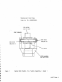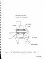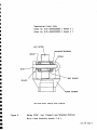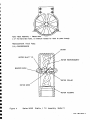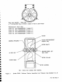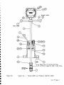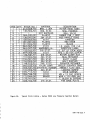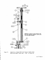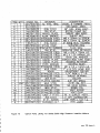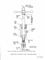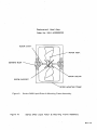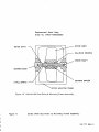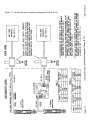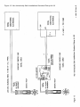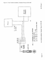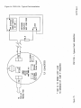
1
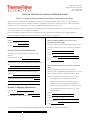
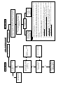
Series 5000 & 5400
Insertion Turbine Flowmeters
User Guide
P/N 057-0352-004
Revision A
Part of Thermo Fisher Scientific
Series 5000 & 5400
Insertion Turbine Flowmeters
User Guide
P/N 057-0352-004
Revision A
©2007 Thermo Fisher Scientific Inc. All rights reserved.
All trademarks are the property of Thermo Fisher Scientific Inc. and its subsidiaries.
Thermo Fisher Scientific (Thermo Fisher) makes every effort to ensure the accuracy and completeness of
this manual. However, we cannot be responsible for errors, omissions, or any loss of data as the result of
errors or omissions. Thermo Fisher reserves the right to make changes to the manual or improvements to
the product at any time without notice.
The material in this manual is proprietary and cannot be reproduced in any form without expressed
written consent from Thermo Fisher.
Thermo Fisher Scientific
1410 Gillingham Lane
Sugar Land, TX 77478
USA
Phone: 713-272-0404
Fax: 713-272-2272
Web: www.thermofisher.com
Thermo Fisher Scientific
14 Gormley Industrial Avenue
Gormley, Ontario L0H 1G0
Canada
Phone: 905-888-8808
Fax: 905-888-8828
This page intentionally left blank.
Series 5000 & 5400
INSERTION TURBINE FLOWMETERS
SERIES 5000 & 5400
HANDBOOK
Rev. A
Issue Information
Issue
Description
0
CN 8653
A
Per ERO 5982
Thermo Fisher Scientific
Series 5000 & 5400
This page is blank
Thermo Fisher Scientific
Series 5000 & 5400
SAFETY NOTICE
Read this manual before working with the
product. For personal and system safety, and
optimum product performance, make sure
you thoroughly understand the contents
before installing, using or maintaining this
product.
YOU ARE RESPONSIBLE FOR YOUR OWN
SAFETY AND THAT OF YOUR COLLEAGUES.
Be aware of the weight of meters and the
component parts as meters increase in size.
Safety boots/shoes and eye protection must
be worn whenever bench work is undertaken.
Use lifting gear as appropriate, or at certain
assembly or disassembly stages, enlist extra
help.
Note: some items have sharp edges and
corners.
For equipment service, please contact
Thermo Fisher Scientific.
Thermo Scientific products satisfy all obligations arising from European Union legislation
to harmonise product standards.
Thermo Fisher Scientific
Series 5000 & 5400
This page is blank
Thermo Fisher Scientific
Series 5000 & 5400 Insertion Turbine Flowmeters
SECTION 1
INTRODUCTION
SECTION 2
SAFETY
INDEX
Page No.
Purpose
Applicability
Other Sources of Information
1-1
1-2
1-2
Control of Substances Hazardous to Health
Pressure Hazards
Electrical Safety
Meter Protection
Handling
Pick-ups
Installed Protection
2-1
2-1
2-1
2-1
2-1
2-2
2-2
SECTION 3
GENERAL DESCRIPTION
Principles of Operation
Series 5000 Turbine Meters
Series 5400 Turbine Meters
3-1
3-1
3-3
Flow Straightening
Tanks
Air Entrainment
Filtration
Liquid Meters with Sleeve Bearing
Liquid and Gas Meters with Ballrace Bearing
Installation Series 5000
Series 5400
4-1
4-1
4-2
4-2
4-2
4-2
4-2
4-4
General Notes
5-1
SECTION 4
INSTALLATION
SECTION 5
MAINTENANCE
Index Page 1
Thermo Fisher Scientific
Series 5000 & 5400 Insertion Turbine Flowmeters
INDEX
SECTION 6
INSPECTION AND
REPAIR
Series 5000
Insertion / Turbine Assemblies
Selection of a Turbine Head Assembly
Removal of Stem / Pick-up Assembly
Low Pressure Collet Clamp Models
High Pressure Screw Jack Models
Replacement of Seals and Scraper Rings
Removal / Replacement of Rotor Assembly
Series 5400
Removal / Replacement of the Turbine Capsule
Stem Seal and Scraper Ring
Pick-up Assembly
6-1
6-1
6-2
6-3
6-3
6-4
6-4
6-4
6-5
6-5
6-6
6-6
Direct Volumetric
Calibration as a Velocity Measuring Device
Computation of Calibration Constants
Sample Flow Calculations – Example 1 (Metric)
Velocity Check
Profile Factor Computation
Blockage Factor
Application of Profile and Blockage Factors
Frequency for Full Scale Output – Analogue Scaling
Estimation of Disturbance Effects
Sample Flow Calculations – Example 1 (Imperial)
Velocity Check
Profile Factor Computation
Blockage Factor
Application of Profile and Blockage Factors
Frequency for Full Scale Output – Analogue Scaling
Estimation of Disturbance Effects
Table 1 Flow Blockage Factors (Liquid)
Table 2 Flow Blockage Factors (Gas)
Table 3 Average Profile Factors
Flow Disturbance Factors
7-1
7-1
7-2
7-3
7-3
7-3
7-3
7-4
7-4
7-4
7-6
7-6
7-6
7-6
7-7
7-7
7-7
SECTION 7
CALIBRATION
Index Page 2
Thermo Fisher Scientific
Series 5000 & 5400 Insertion Turbine Flowmeters
INDEX
SECTION 8
TROUBLE SHOOTING
Pick-ups
Fault Finding Chart
8-1
8-2
SECTION 9
APPENDIX
Figure 1
Figure 2
Figure 3
Figure 4
Figure 5
Figure 6a
Figure 6b
Figure 7a
Figure 7b
Figure 8
Figure 9
Figure 10
Figure 11
Figure 12
Figure 13
Figure 14
Figure 15
Index Page 3
Series 5000 Model 1 Head
Series 5000 Model 2 Head
Series 5000 Models 3-4 Head
Series 5000 Model 5 Head
Series 5000 Models 6-9 Head
Series 5000 Low Pressure
Available Parts Listing
Series 5000 High Pressure
Available Parts Listing
Series 5400 Assembly
Series 5400 Capsule (Liquid)
Series 5400 Capsule (Gas)
Inter-Connections – IS / A10
Inter-Connections – non IS / A10
Inter-Connections – non IS / SQ2
Inter-Connections – FDC1100
Inter-Connections – A30
Thermo Fisher Scientific
Series 5000 & 5400 Insertion Turbine Flowmeters
INDEX
This page is blank
Index Page 4
Thermo Fisher Scientific
Series 5000 & 5400 Insertion Turbine Flowmeters
INTRODUCTION
SECTION 1
Introduction
The development of the insertion turbine meter has resulted
from the demand for accurate flow measurement in medium
and large diameter pipes, especially in cases where ease of
installation is essential, and the cost of full-bore meters
prohibitive. Typical applications include water service,
chemicals, oil and petroleum products.
The insertion turbine meter is a flow velocity-measuring device.
When used in a pipe of known cross-sectional area its
associated electronics may be calibrated to indicate volumetric
flow directly in engineering units such as barrels per hour
(BPH), litres per minute (LPM), gallons per minute (GPM), etc.
The insertion turbine meter may be used in conjunction with
batch controllers, BTU computers or conventional flow rate and
totalization indicators.
Thermo Fisher’s insertion turbine flowmeter consists of a
magnetically permeable rotor assembly installed in magnetically
impermeable stainless steel housing. The housing is attached
to a stainless steel stem in which the magnetic pick-up is
located. The pick-up senses the rotation of the rotor and a
pulse is produced each time a rotor blade passes through the
magnetic field of the pick-up.
The speed of the blade rotation, and consequently the output
frequency of the pick-up, is dependent upon the rate at which
the media is flowing through the meter.
There are two limits to this flow range: a lower limit, below
which mechanical friction and magnetic drag prevent the rotor
from turning at a speed sufficient to generate pulses, and a
higher limit beyond which damage and/or accelerated wear will
occur. Between these limits, the flowmeter will produce a
virtually constant number of pulses for each unit volume of
media, regardless of the rate at which the flow occurs.
1.1 Purpose
Section 1 Page 1 of 2
This manual has been laid out to give the end user guidance on
installation, detailed maintenance procedures, and spare parts
availability. Installation is introduced by an explanation of the
principles involved in liquid and gas flow metering using
insertion turbine flowmeters. All turbine meters require a pickup, to provide a measurable electrical output, and in turn there
are electronic accessories that may be connected to the pick-up
output to condition or enhance the signal for onward
transmission.
Thermo Fisher Scientific
Series 5000 & 5400 Insertion Turbine Flowmeters
Applicability
INTRODUCTION
The information contained in this manual is applicable to
Thermo Fisher’s insertion turbine flowmeters fitted with sleeve
or ballrace bearings. The information contained herein is not
influenced by the type of process connection with which
individual flowmeters are provided, e.g. flanged, threaded etc.
The basic designs of the series 5000 and 5400 flowmeter vary.
As a result of this, for the purposes of describing maintenance
procedures, the meters have been divided into two categories,
as follows:
Series 5000
Series 5400
Other Sources of
Information
For specific details of meter types available, operating ranges,
special applications, accessories, physical dimensions etc.,
reference should be made to the current datasheet:
Insertion Turbine Flowmeter Series 5000
Insertion Turbine Flowmeter Series 5400
If there are any doubts regarding the proposed use or
installation of the meter/s supplied, please contact Thermo
Fisher.
Technical Notes are available containing detailed performance
specifications and application requirements for all types of
turbine meter. For insertion meters fitted with sleeve bearings
or ballrace bearings the following publication is available:
Technical Note 006: Insertion Turbine Flowmeter Application
Guide
Thermo Fisher offers a full service and calibration facility.
Section 1 Page 2 of 2
Thermo Fisher Scientific
Series 5000 & 5400 Insertion Turbine Flowmeters
SECTION 2
SAFETY
Safety – Important Notice
Safety
Control Of Substances
Hazardous To Health
Many metering installations involve the measurement of
hazardous fluids. Before removal from service it is important to
ensure that the COSHH data is available and appropriate
protective measures are taken.
In addition there may be site specific procedures relating to
protective clothing and hazard handling. Ensure that such
procedures are adhered to.
Pressure Hazards
An insertion turbine meter is considered as a pressure
accessory by the Pressure Equipment Directive. Care must be
exercised to ensure that the line section is isolated, drained and
relieved of pressure before the meter is removed. Read
warning labels affixed to the instrument before removal. Before
installing new equipment check that the instrument service
limits are compatible with the line conditions into which the
meter is to be placed in service. The customer is responsible
for ensuring that all equipment is protected against overpressurisation, including that caused by external fire.
Electrical Safety
Before starting any work, ensure that the power connections
are isolated and precautions are taken to prevent power being
restored whilst work is taking place. Particular attention should
be paid to installation conditions specified for hazardous areas
(below). Such installations forbid the use of tools or equipment
which could produce an explosion hazard.
Hazardous Area Use
Special conditions apply to meters certified for installation in a
hazardous area. Details of permissible installation conditions
(ambient temperature, maximum surface temperature and gas
groups) are provided on the labels affixed. In addition such
equipment may only be installed in hazardous areas classified
appropriate to the method of protection. Thermo Scientific
flowmeters may be certified to EEx(d) for use in Zone I or Zone
II areas or certified to EEx (ia) for Zone 0 applications.
Meter Protection
Handling
Section 2 Page 1 of 2
DO NOT subject the meter or the pick-up to excessive shock
loading - never use hammers or mallets. Shock loading can
shatter tungsten carbide parts in the meter internals. DO NOT
allow foreign bodies (dirt or swarf ) to enter the meter bearings.
Note: Surface damage to any of the meter’s turbine head
parts can affect its performance.
Thermo Fisher Scientific
Series 5000 & 5400 Insertion Turbine Flowmeters
SAFETY
DO NOT use airlines or hoses - any pressured source of air/gas
or liquid - to check or clean a meter. (It may be ultrasonically
cleaned). If a rotor is allowed to over-speed serious bearing
damage may occur.
Pick-Ups
These form part of the meter body and can not be removed
while the meter is in service.
Installed Protection
AVOID sudden shocks e.g. sudden filling of the process line
with a liquid. The trapped air will cause rapid acceleration of the
turbine and potential over-speeding. ALWAYS introduce a
liquid slowly (relate to the meter range and DO NOT exceed its
normal maximum flowrate).
Marking
The Series 5000/5400 range of turbine meters is marked (when
specified) for use in hazardous areas as required by the ATEX
Directive.
Certification is currently held for Group II Category 2 gases.
The protection concept is Flameproof, Temperature Class 4
with a maximum ambient temperature of 55°C.
The equipment marking includes the following information:-
Section 2 Page 2 of 2
ATEX Certificate No BAS02ATEX2150
II 2G
EEx d IIB T5 (-20°C ≤ Ta ≤ 55°C)
The maximum voltage
The maximum power dissipation in mW
Thermo Fisher Scientific
1410 Gillingham Lane
Sugar Land, TX 77478 USA
Tel: 713.272.0404
Fax: 713.272.2272
HEALTH AND SAFETY (COSHH) CLEARANCE FORM
Failure to comply with this procedure will result in equipment service delays.
This form must be completed for all equipment returned to Thermo Fisher Scientific (Thermo Fisher) – Sugar Land Depot
Repair. Depot repair personnel are unable to handle any equipment that has been in contact with a process fluid or hazardous
material if it is not accompanied by this correctly completed Health and Safety Clearance Form.
All sections of this form must be completed, and the form must arrive at Thermo Fisher prior to the arrival of the equipment. A
copy of this form must also accompany the equipment.
Prior to returning any equipment for service, authorization must be obtained from customer service. A Return Material
Authorization (RMA) number will be issued and must be entered in Section 1 of this form.
Section 1: Reference Details
Section 4: Declaration
RMA #:
Must be authorized ONLY if non-toxic or nonhazardous substances apply.
Equipment type:
Serial #:
I hereby confirm that the equipment specified above has not
come into contact with any toxic or hazardous substances.
Section 2: Process Fluid Information
Signed:
All substances in contact with the equipment must be
declared.
Name:
Position:
For/on behalf of:
Chemical names (list all):
Date:
Precautions to be taken when handling these substances (list
all):
Must be authorized if toxic or hazardous substances
apply.
Action to be taken in the event of human contact or
spillage:
I hereby confirm that the only toxic or hazardous
substances that the equipment specified has been in contact
with are named in Section 2, that the information given is
correct, and that the following actions have been taken:
Additional information you consider relevant:
1.
The equipment has been drained and flushed.
2.
The inlet/outlet ports have been sealed, and the
equipment has been securely packed and labeled.
3.
The carrier has been informed of the hazardous nature
of the consignment and has received a copy of this
completed form.
Section 3: Shipping Information
Carrier details:
Tel:
Signed:
/ Fax:
Scheduled delivery date to Thermo Fisher:
Name:
Position:
For/on behalf of:
Date:
A copy of this completed form MUST BE HANDED TO THE CARRIER to accompany the equipment.
Form No.: QF_COSHH
ECO: 5424
REV: B
Date 12-08-06
This page intentionally left blank.
Series 5000 & 5400 Insertion Turbine Flowmeters
GENERAL
DESCRIPTION
SECTION 3
General Description
Principles of Operation
The turbine flowmeter is essentially a velocity-measuring
device, which is calibrated to indicate volumetric flow of liquid or
gas in a pipeline. The operation of the flowmeter is based upon
the speed (angular velocity) of a freely supported rotor, which
revolves at a rate directly proportional to the flow rate of the
medium.
The rotor blades cut a magnetic field set up by a permanent
magnet assembly which is installed in a pick-up unit in the
flowmeter stem.
The pick-up is constructed of a coil placed adjacent to a
permanent magnet and wound on to a former. The former is
positioned over a ferromagnetic core, which is arranged such
that it is close to a turbine meter rotor blade when it passes
underneath.
The change in flux density resulting from the passage of rotor
blades induces a voltage across the coil. The generated
frequency is proportional to the speed of the rotor. The number
of pulses per unit volume is established during calibration and
is termed "The Calibration Constant". The variation of this
constant over a specified rate of flow range is defined as the
meter linearity.
The pulses are fed to appropriate electronic units or computer
interface cards for processing to provide totalized and rate of
flow readouts.
Series 5000
The Series 5000 Insertion Turbine Flowmeter range has been
designed to meet a requirement for a cost effective, versatile
measurement system in medium and large diameter pipes.
Its particular attributes are ease of installation
maintenance, wide rangeability and linear pulse output.
and
The Series 5000 flowmeter is an inferential velocity measuring
device but may be used to measure mass and volumetric flow,
provided adequate information is available concerning the
pipework configuration, dimensions and flow parameters.
The achievable installed accuracy depends largely on how
carefully the application conditions are considered in order to
establish appropriate correction factors or if an on-site
calibration is carried out.
Section 3 page 1 of 4
Thermo Fisher Scientific
Series 5000 & 5400 Insertion Turbine Flowmeters
GENERAL
DESCRIPTION
As a velocity-measuring device, linearity is typically ±1% of
reading at low viscosity over a 10:1 rate of flow range.
Volumetric flow rate errors and repeatability errors are a
function of the individual installation. Practically speaking, for
most applications the total measurement non-linearity will be
around ±2% of reading over a 10:1 rate of flow range.
Repeatability is normally better than ±2% for a 95% confidence
limit.
The flowmeter is modular in design whereby the major
components can be assembled to meet the application
requirement. A choice of insertion assemblies can be fitted with
a range of interchangeable turbine assemblies – thus allowing a
specific measurement problem to be solved precisely and cost
effectively. In addition many specialised options are available to
meet a wide range of more demanding application
requirements.
The insertion assembly (see Section 8 Figures 6a/7a) is fitted
with a fluid seal and scraper to meet most pipeline and
industrial requirements including sour crude applications. A
plain stem passes through the seal arrangement, which is held
either by a simple collet lock and manually inserted for low
pressure use or the stem is fitted with a screw jack mechanism,
for high-pressure use.
The screw jack mechanism serves to restrain the stem against
line pressure and to provide a convenient means of insertion
and retraction under pressure.
It is mandatory that the screw jack mechanism is fitted when
operating at pressure above 19 bars.
Note: the screw jack mechanism is not subject to line
pressure.
Section 3 page 2 of 4
Thermo Fisher Scientific
Series 5000 & 5400 Insertion Turbine Flowmeters
Series 5400
GENERAL
DESCRIPTION
Thermo Fisher’s series 5400 insertion turbine flowmeter has
been designed to provide an economical, accurate and reliable
measurement device for the flow of water and other medium
viscosity liquids.
It is an inferential velocity measuring device but can be used to
measure volume flowrates provided the pipe diameter and
upstream configurations are known.
The series 5400 flowmeter will perform with peak overall
accuracy if it is calibrated on-site. Otherwise, the achievable
installed accuracy will depend on how carefully application
conditions are considered when establishing the appropriate
correction factors.
It is available with an option on the type of pick-up, this being
either the standard or bi-directional type. The standard pick-up
gives a pulsed output at a frequency proportional to flow
velocity. With the bi-directional option, there are two outputs
which are out of phase. This phase difference can be
electronically processed to give the direction of flow.
Both pick-ups are magnetic and are fully encapsulated. They
perform reliably with a wide temperature capability and
excellent immunity to shock and vibration.
The low inertia rotor is mounted on a solid tungsten carbide
pinion, which rotates in a stellite bearing sleeve. This rotor
assembly plus the mounting frame is referred to as a capsule
and is available pre-calibrated for simple maintenance (see
Section 8, Figures 10 and 11).
The design of the capsule is the reason for the excellent
performance of the 5400 insertion meter. The meter is capable
of measuring extremely low flow rates. Also, due to the relative
immunity of the bearing configuration to the ingress of solid
particles, the meter can be left in position and unattended for a
considerable period of time.
The stem seal combines as a locking ring for positioning the
meter in the pipeline. It has a progressive unlocking action
making it safe to use in pressurised pipes (see Section 8,
Figure 9).
Section 3 page 3 of 4
Thermo Fisher Scientific
Series 5000 & 5400 Insertion Turbine Flowmeters
GENERAL
DESCRIPTION
This page is blank
Section 3 page 4 of 4
Thermo Fisher Scientific
Series 5000 & 5400 Insertion Turbine Flowmeters
INSTALLATION
SECTION 4
Installation – General
Notes
The Thermo Scientific range of insertion turbine flowmeters has
been designed to give high accuracy with long term stability
and operating life. To ensure this it is recommended that the
following points be considered during installation.
All meters have the "Direction of Flow" marked on the body. In
the case of the insertion meter this is indicated by the use of
red and black handles. The red handle must point upstream
and be inline with the process pipe. Incorrect flow direction will
produce an installed calibration error.
Flow Straightening
The main requirement for turbine meter flow measurement is
repeatability i.e. for any particular flow rate the same number of
pulse per unit volume is obtained. This can only be achieved if
the liquid or gas is flowing smoothly and fully "axially" in the
pipe (i.e. there is no "swirl" or flow pulsation).
If the upstream pipe work, for a distance of at least twenty pipe
diameters, has no fittings such as valves (other than full flow
gate or ball valves) or bends, (other than large radius, tees etc)
then a minimum length of clean bore pipe of ten flowmeter pipe
diameters should be provided immediately upstream of the
meter.
Wherever any fittings or pumps are installed upstream of the
meter, then a length of pipe of twenty diameters should be
provided.
The best practice is to use a Thermo Scientific flow
straightener.
Downstream conditions can "reflect back" on a meter. Usually it
is satisfactory to halve the straightener pipe lengths stated
above. The API manual of flow measurement recommends ten
diameters of straight pipe upstream and five diameters
downstream as a minimum.
Tanks
(Liquid Applications)
Section 4 Page 1 of 6
Where the flowmeter is installed in a line fitted to the bottom of
a storage vessel it is advisable to fit a baffle plate over the hole
in the tank in order to prevent the liquid vortexing through the
flowmeter.
Thermo Fisher Scientific
Series 5000 & 5400 Insertion Turbine Flowmeters
Air Entrainment
(Liquid Applications)
INSTALLATION
For liquid applications air entrainment is to be avoided. Where
it is possible that air could be present in the line an air
eliminator may be fitted.
Filtration
Liquid Meters With
Sleeve Bearing
Extremely fine filtration is not required with sleeve bearings.
However, a coarse filter should be fitted upstream of the
flowmeter for protection against damage by pipe scale, welding
splatter and other foreign material.
Recommended filter mesh sizes are as follows:
Perforation Size: 0.2mm (0.0079”)
Liquid And Gas Meters
With Ballrace Bearing
Mesh Size: 80
Good filtration is recommended for meters fitted with ball
bearings for liquid or gas use.
Recommended filter size:
Perforation Size: 20 micron
SERIES 5000
Installation Mechanical
The Series 5000 Insertion Meter is installed through a 3-inch
nominal bore tee piece positioned at a right angle to the
process pipe. An isolating valve (3” full bore) should be fitted to
the tee to enable installation/removal of the meter under
pressure.
The Series 5000 Insertion Meter seal housing is flanged to BS
1506 as standard to ASA 150 RF, ASA 300 RF, ASA 600 RF,
ASA 900 RF or ASA 1500 RF as required. It is important to
ensure the attachment flange is specified to match. If the
insertion meter has been ordered with non-standard flanges,
similarly the attachment flange should be checked.
The critical depth is the point on a fully developed velocity
profile where the local sensed velocity is equal to the average
velocity. This occurs at a distance from the pipe wall of 0.12D
where D is the pipe diameter. Critical depth insertion is only
recommended for large pipes greater than 20” diameter. No
blockage or profile factors are required to compute a calibration
constant if this method of installation is employed.
The insertion tee piece should be positioned to give as much
upstream straight pipe as possible to avoid flow disturbance
errors, which become significant for straight lengths less than
20 diameters. In all cases there should be 5 diameters of
downstream straight pipe.
Section 4 Page 2 of 6
Thermo Fisher Scientific
Series 5000 & 5400 Insertion Turbine Flowmeters
Series 5000 continued
INSTALLATION
If upstream straight pipe lengths are less than 10 diameters,
then a flow straightener may be used to produce a flat velocity
profile and minimise swirl errors.
In unfavourable pipe configurations where swirl and velocity
profile distortion is severe, considerable errors will occur unless
an on site calibration is carried out.
The turbine axis must be positioned to the pipe centre line or
the pipe critical depth as required. This means that the distance
between the pipe inner wall and the top of the connection tee
must be measured to enable the insertion meter stem to be
marked for subsequent accurate positioning to depth.
The high-pressure insertion assembly contains the insertion
stem relative to flanged assembly. In order that the jack
assembly and the stem line up with the pipe centre line, the
flanged tee piece should be welded to the pipe with the
bolt- holes in line with the pipe centre line for ASA 300
ratings and above (8 holes). For ASA 150 connection the
flange should be welded so that the bolt-holes straddle the
pipe centre line (4 holes).
Finally, it is important to ensure that the leading edge of the
rotor points in the direction of flow. On the low-pressure unit the
turbine head is set such that the red handle knob points
upstream whereas on the high-pressure unit the conduit box
faces upstream.
Installation – Electrical
Section 4 Page 3 of 6
With the meter installed in the line, wiring to companion
electronics should be attached such that a flexible service loop
will allow full insertion and retraction. See interconnections as
illustrated in Figures 10 and 11.
Thermo Fisher Scientific
Series 5000 & 5400 Insertion Turbine Flowmeters
SERIES 5400
Installation Mechanical
INSTALLATION
The Series 5400 Insertion Flowmeter is easily installed. It is
manufactured with a 1.5” BSPT or NPT process connection
which can be fitted directly into a pipe through a tapping point. It
can also be fitted into a pressurised pipeline through a 2” gate
valve.
When fitting the series 5400 insertion meter in an empty
pipeline only a threaded entry point is required to be welded to
the outside of the pipe.
If the pipe is full and pressurised then the meter can still be
installed or removed but this now has to be performed via a
gate valve. Proprietary kits are available for this type of
arrangement.
Note at this stage it is important for the insertion meter to enter
the pipe at a 90° angle to the axis. Also, the meter should be
positioned where there is the least possible disturbance of the
flow. This normally means positioning the meter with at least
20 pipe diameters of straight pipe upstream and 5 diameters
downstream from the nearest fitting or valve.
If the meter can only be fitted in an area of high swirl and
velocity profile distortion, considerable errors will occur unless
the meter is calibrated on site.
It is also important to ensure that the leading edge of the rotor
points in the direction of flow. The 5400 is constructed such
that the handle with the red knob should point upstream.
Finally, the turbine axis must be set on the pipe centre line or at
the pipe critical depth, as required.
The critical depth is the point on a fully developed velocity
profile where the local sensed velocity is equal to the average
velocity. This occurs at a distance from the pipe wall of 0.12D
where D is the pipe diameter. Critical depth insertion is only
recommended for large pipes greater than 20” diameter. No
blockage or profile factors are required to compute a calibration
constant if this method of installation is employed.
Section 4 Page 4 of 6
Thermo Fisher Scientific
Series 5000 & 5400 Insertion Turbine Flowmeters
Series 5400 continued
INSTALLATION
If the distance from the underside of the handle boss to the top
of the seal housing is used to gauge the insertion depth, then
let this dimension be termed X where:
X=L+Z–A–B
Where (consult Figure9):X = Variable height of underside of handle above seal housing
L = distance from turbine axis to underside of handle
Z = Distance of turbine axis from bottom of pipe (half of internal
diameter if meter positioned on centre line)
A = Distance from bottom of pipe to top of threaded entry point
B = distance from top of threaded entry point to top of seal cap
Therefore before the meter is installed, the measurements of L,
A, and Z should be known. B can be measured once the meter
is installed. Finally the distance X can be calculated and the
meter adjusted by loosening the blots on the seal housing and
sliding the stem into the required position. Before tightening the
bolts, ensure that the red knob on the handle is pointing
upstream of the flow.
Now loosen the locking ring on the stem and slide it downwards
until it makes contact with the seal cap. Lock in position. This
will facilitate easy re-setting should the meter be withdrawn for
any reason provided it is used in the same sized pipeline and
with similar fittings.
Electrical
Section 4 Page 5 of 6
See interconnections as illustrated in Section 8, Figures 12-16.
Thermo Fisher Scientific
Series 5000 & 5400 Insertion Turbine Flowmeters
INSTALLATION
This page is blank
Section 4 Page 6 of 6
Thermo Fisher Scientific
Series 5000 & 5400 Insertion Turbine Flowmeters
MAINTENANCE
SECTION 5
Maintenance
Note: When making an enquiry concerning a particular
instrument, please have the serial number of the
instrument to hand.
General Notes
No maintenance can be carried out on the internal parts of this
type of meter whilst it is in operation. The only maintenance is
to the external parts of the meter, ie electrical enclosures,
electrical signal conditioning units and circuits.
ENSURE THAT ALL ELECTRICAL SUPPLIES ARE ISOLATED
BEFORE CARRYING OUT ANY MAINTENANCE WORK
Section 5 Page 1 of 2
Thermo Fisher Scientific
Series 5000 & 5400 Insertion Turbine Flowmeters
MAINTENANCE
This page is blank
Section 5 Page 2 of 2
Thermo Fisher Scientific
Series 5000 & 5400 Insertion Turbine Flowmeters
INSPECTION &
REPAIR
SECTION 6
Inspection and Repair
SERIES 5000
Insertion Assemblies
Note: When making an enquiry concerning a particular
instrument, please have the serial number of the
instrument to hand.
The choice of insertion assembly and flange is dictated by the
pressure-rating requirement. The standard flange offered is
machined to ANSI Bl6.5 (BS 1560) with a raised face. Other
flange specifications are available to order.
A choice of either Collet clamp or screw jack mechanism is
available.
NOTE: THE COLLET CLAMP ASSEMBLY MUST NOT BE
USED AT LINE PRESSURE IN EXCESS OF 19 BARS.
Type
Collet clamp
Screw jack
Screw jack
Screw jack
Screw jack
Turbine Assemblies
Flange rating
ASA
150
150
600
900
1500
Maximum pressure
BarG
19
19
98
147
200
The selection of the correct turbine assembly is dictated by the
application requirement. The type of rotor bearing used is
governed by the media encountered and the required velocity
range; for example, general purpose liquid use with no filtration
would require a hard metal sleeve bearing whereas clean liquid
or gas would require a ball bearing assembly. The type of
bearing selected and in the case of gas applications, the
pressure, determines the total velocity range and linear flow
range of the meter.
For low-pressure gas it is necessary to minimise frictional drag
forces and increase the turbine blade area in order to extract as
much energy as possible from the gas flow. All types of turbine
assembly are interchangeable and the various configurations of
rotor and bearings available can be selected.
By selecting the required insertion assembly from the previous
table and turbine assembly from the table on the following page
a model number can be defined for the required application.
Section 6 Page 1 of 6
Thermo Fisher Scientific
Series 5000 & 5400 Insertion Turbine Flowmeters
INSPECTION &
REPAIR
Code
Number
1
2
3
4
5
6
7
8
9
10
Turbine type
Application
Cast rotor fitted with
tungsten carbide pinion with
stellite sleeve bearings
Machined rotor fitted with
shielded ballrace bearings
General liquid use,
no filtration required
Machined rotor fitted with
pre-lubricated shielded
ballrace bearings
Machined rotor fitted with
pre-lubricated shielded
ballrace bearings
Chemically etched shrouded
rotor with tungsten carbide
pinion with stellite sleeve
bearings
Chemically etched shrouded
rotor with pre-lubricated
shielded ballrace bearings
(35° blade angle)
Chemically etched shrouded
rotor with pre-lubricated
shielded ballrace bearings
(45° blade angle)
Chemically etched shrouded
rotor with pre-lubricated
shielded ballrace bearings
(64o blade angle)
Chemically etched shrouded
rotor with pre-lubricated
shielded ballrace bearings
(76o blade angle)
Cast rotor with tungsten
carbide pinion and synthetic
sapphire coned bearing
Linear
range
m/sec
Linear
range
ft/sec
1.0 to 12.0
3.3 to 39.4
0.6 to 12.0
2.0 to 39.4
2.0 to 30.0
6.6 to 98.4
High pressure gas
High velocity range
4.0 to 45.0
3.0 to 150.0
General liquid use
Low velocity range
0.3 to 5.0
1.0 to 16.4
Low pressure gas
Low velocity range
0.6 to 6.0
2.0 to 19.7
1.2 to 12.0
3.9 to 39.4
3.0 to 30.0
9.8 to 98.4
5.0 to 50.0
16.4 to 164.0
2.0 to 30.0
6.6 to 98.4
Clean liquids with
lubricating
properties
High pressure gas
(over 10barG)
Low pressure gas
Medium velocity
range
Low pressure gas
High velocity range
Low pressure gas
Very high velocity
ranges
Steam
High velocity range
11
Cast rotor with tungsten
carbide pinion and synthetic
sapphire coned bearing
Steam
Medium velocity
range
1.0 to 18.0
3.3 to 59.0
12
Cast rotor with tungsten
carbide pinion and synthetic
sapphire coned bearing
Steam
Very high velocity
range
6.0 to 60.0
19.7 to 197.0
Section 6 Page 2 of 6
Thermo Fisher Scientific
Series 5000 & 5400 Insertion Turbine Flowmeters
INSPECTION &
REPAIR
Maintenance
The major component identification is given in Figure 6a and
Figure 7a for the high and low-pressure variants. In addition, a
detailed parts listing is given in Figures 6b and 7b.
From these four figures all the components and sub-assemblies
are identified with the exception of the turbine heads. These
are illustrated with part numbers in Figures 1-5. It is possible to
order spares by part number for commissioning and/or service;
however if a spare turbine rotor or turbine assembly is ordered
it is important to specify the instrument model and required
velocity range.
The following procedures should be observed in conjunction
with the assembly drawings for maintenance.
Series 5000
Removal Of Stem / PickUp Assembly
Low Pressure
Collet Clamp Models
BEFORE COMMENCING ANY WORK PLEASE REFER TO
SECTION 2 (SAFETY) AND ENSURE THAT IT IS SAFE TO
DO SO.
•
Disconnect field wiring and connections from the pick-up
coil to the conduit box mounted terminal block.
•
Remove securing grub screws from handle boss assembly
and remove the assembly complete
•
Slacken collet clamp and withdraw stem with the turbine
assembly attached through the seal housing.
•
Remove the turbine assembly by slackening and
unscrewing the stainless steel lock nut. The stem and pickup assembly as well as the turbine assembly are
replaceable as complete units; however, the turbine
assembly itself may be dismantled for cleaning as
described later.
Replacement of the stem/pick-up assembly is the reverse of the
procedures described except that it is important to note that
axis of the turbine must be in line with the handle assembly.
The front (upstream) side of the turbine must face towards the
red knob.
The pick-up should have a DC resistance of between 600-1000
ohms (standard coil) and should give a minimum output of 40
mV at 50Hz when tested as a complete assembly by spinning
the rotor.
Section 6 Page 3 of 6
Thermo Fisher Scientific
Series 5000 & 5400 Insertion Turbine Flowmeters
INSPECTION &
REPAIR
BEFORE COMMENCING ANY WORK PLEASE REFER TO
SECTION 2 (SAFETY) AND ENSURE THAT IT IS SAFE TO
DO SO.
Series 5000
•
Disconnect field wiring and connections from the pick-up
coil to the conduit box mounted terminal block.
High Pressure Screw
Jack Models
•
Remove securing grub screws from the handle boss
assembly and remove the assembly complete.
•
Remove two socket cap screws securing the insertion stem
carrier cover and remove cover.
•
Remove the high-pressure retractor mechanism by
unscrewing the four retaining bolts on the seal housing.
•
Withdraw the insertion stern/pick-up assembly complete
with the turbine assembly attached through the seal
housing.
•
Remove the turbine assembly by
unscrewing the stainless steel locknut.
slackening
and
Replacement is the reversal of the above except that the
turbine axis must be parallel with a line drawn through the stem
and retractor assembly centre lines. The front of the turbine
(upstream) must face away from the retractor assembly. The
pick-up output may be checked as described.
Replacement Of Seals
And Scraper Rings All Models
•
Remove insertion stem/pick-up assembly as described.
•
Remove collet lock assembly (low pressure models) and
withdraw seal from assembly.
•
Remove scraper retaining plate from inside seal housing
(by unscrewing four retaining screws).
•
Withdraw scraper ring.
Replacement is the reversal of the above, but ensure that
machined recesses for new seals are cleaned out and
corrosion free.
Removal / Replacement
Of Rotor Assembly
Section 6 Page 4 of 6
A complete new rotor assembly should be fitted (do not attempt
to repair). Contact Thermo Fisher.
Thermo Fisher Scientific
Series 5000 & 5400 Insertion Turbine Flowmeters
INSPECTION &
REPAIR
SERIES 5400
BEFORE COMMENCING ANY WORK PLEASE REFER TO
SECTION 2 (SAFETY) AND ENSURE THAT IT IS SAFE TO
DO SO.
Maintenance
All components of the 5400 insertion meter can be identified by
consulting the assembly drawing and parts list (see Section 8
Figures 9 to 11). Parts required for commissioning or service
can be ordered by quoting the part number or identifying the
sub-assembly. Note: when enquiring please have the serial
number of the instrument to hand.
Maintenance work is likely to be minimal. The turbine capsule
can be replaced as a complete and pre-calibrated unit. The
only other part which may require to be replaced occasionally is
the stem seal.
The following procedures should be observed with the aid of
the assembly drawing.
Removal / Replacement
Turbine Capsule
Loosen the two grub screws in the rotor head cage. (See
Section 8, Figure 9, item 4)
Withdraw the rotor capsule. (item 3)
Replacement of new capsule is in reverse order. Take note of
the direction of flow arrow etched on the rotor cage; this should
point from the red knob to the black knob on the handle.
Ensure rotor spins freely after assembly.
Section 6 Page 5 of 6
Thermo Fisher Scientific
Series 5000 & 5400 Insertion Turbine Flowmeters
INSPECTION &
REPAIR
Series 5400 continued
Stem Seal And Scraper
Ring
•
Disconnect field wiring and pick-up leads to either the
logger interface of terminal block inside conduit box.
•
Loosen handle grub screws and slid off handle boss (See
Figure 9 item 7).
•
Remove depth setting lockring (item 5).
•
Undo three cap screws and remove seal cap (item 1B).
•
Remove stem seal (item 1C).
•
Gently remove scraper ring from groove inside seal cap.
(item 1D).
•
Replacement of new seal and scraper ring is in reverse
order to above.
Note when replacing the handle boss assembly the red knob
should point upstream of the flow. Therefor it is important that
the handle lines up with the axis of the turbine assembly.
Pick-Up Assembly
The pick-up can only be replaced as a complete assembly
comprising the pick-up, stem and rotor head cage.
Both types of pick-up coil should have a DC resistance of
between 500 and 1000 ohms and should give a voltage output
of 40 +/- 10mV at 100Hz.
Should the pick-up assembly require replacement then the
procedure is similar to the procedure for removing/replacing the
stem seal.
Once the stem seal has been removed, the stem assembly can
be withdrawn from the seal housing. The rotor can then be
transferred from the old rotor head (capsule) to the new one,
and the new head/stem replaced.
Assembly is in reverse order.
Section 6 Page 6 of 6
Thermo Fisher Scientific
Series 5000 & 5400 Insertion Turbine Flowmeters
CALIBRATION
SECTION 7
Calibration
Direct Volumetric
Most applications call for volumetric measurement and where
this is the case it is often possible to calibrate the meter under
conditions which are identical to those on site.
For a laboratory calibration to be applicable without any adjustments the following conditions must be identical:
•
•
•
•
•
viscosity and density
pipe diameter
upstream pipe configuration
flow range
installation position
Where there are small differences in pipe diameter, it is
possible to correct the laboratory calibration constant by the
area ratio from site.
If the on site viscosity and density is different, small errors will
occur which can either be removed by an extrapolated calibration or by actual site calibrations.
Finally, since the laboratory pipe configuration is such that the
velocity profile is fully developed, it is possible to correct the
calibration constant using a disturbance factor, where the site
pipework configuration is known and if appropriate disturbance
factors are available (see Table 4, at the end of this section).
Calibration As A
Velocity Measuring
Device
This is the standard technique for insertion meter calibration. It
has the advantage that every meter is calibrated in the same
way in a standard pipe section and over a standard velocity
range.
From this basic data, the actual calibration constants expressed
in pulses per unit volume applicable to specific installation can
then be computed.
Thermo Fisher’s water flow laboratory has a number of different
pipe sizes associated with a large meter prover for calibrating
insertion meters.
The diameters of these sections are accurately known and
there is sufficient upstream straight pipe to ensure that the
velocity profile is fully developed. The prover volume is divided
by the section pipe cross section area and corrected for profile
and blockage to give flow length.
Section 7 Page 1 of 8
Thermo Fisher Scientific
Series 5000 & 5400 Insertion Turbine Flowmeters
CALIBRATION
The calibration constant for the meter is thus the pulse count
divided by the appropriate flow length or rig calibration factor for
the pipe size in question.
Computation Of
Calibration Constants
From a volumetric calibration, this is carried out by dividing the
pulse count (obtained over a number of rates of flow) by the
corrected prover volume.
If the field pipe diameter is not exactly the same as the
laboratory pipe diameter, a correction is made as previously
indicated.
Thus from a volumetric calibration a standard calibration sheet
is produced in a similar manner to a full-bore meter and an
average calibration constant computed.
Where the unit is calibrated as a velocity-measuring device, the
calibration constant is computed in pulses per unit length.
Next an appropriate profile factor calculated or read off from
Table 3 (at the end of this section) is applied, computed under
average flow conditions.
After this a blockage factor is applied (Table 1) and a volumetric
computation carried out in accordance with the standard
method using the pipe cross-sectional area.
If the application conditions are gaseous, then the correct
blockage factor must be used (Table 2) and also it may be
necessary to reduce the calibration constant to normal or
standard conditions.
Hence the final calibration constant is produced for a fully
developed profile and for unity viscosity and density (air or
water).
Where the conditions on site depart from these standard
conditions a small shift in calibration constant will be apparent.
This source of error may only be eliminated completely by an
on site calibration. Alternatively, the use of a flow disturbance
factor and/or viscosity correction curves may be obtained from
Thermo Fisher as an estimate to on site performance under
given conditions.
In most cases the accumulation of errors due to viscosity and
disturbance (upstream pipe configuration) errors only amount to
2-3% for a good installation over average flow ranges for the
pipe size in question.
Section 7 Page 2 of 8
Thermo Fisher Scientific
Series 5000 & 5400 Insertion Turbine Flowmeters
Sample Flow
Calculations
Example 1 – Metric
Version
CALIBRATION
The example taken is for a crude oil barge loading application
as follows:
Pipe size:
Flow rate:
SG:
Viscosity:
Pressure:
254mm Schedule 40
600m3/hr
0.855
10 Centistokes
12 bars maximum
Velocity Check
The first stage is to compute the velocity range to ensure that it
is within the capability of the turbine meter selected:
Calculate the selected pipes internal diameter:
Pipe OD 273mm – wall thickness 9.27mm(x2) = 254.46mm
Calculate the pipe area:
Pipe internal diameter radius2 x π / 1000000 = pipe area in m2
Calculate the velocity:
600m³/h
(0.05087m²x 3600) = 3.2m/sec
Profile Factor
Computation
The 273mm pipe installation requires a centre line insertion
position.
From Table 3: The profile factor is 0.825 at the rate of flow of
600m3/hr.
Note that values of profile factor may be interpolated from Table
3 if the operating parameters do not exactly line up with the
values given in the table for flow rate and viscosity.
Blockage Factor
Section 7 Page 3 of 8
For the Model 1 turbine (General Purpose Liquid) the blockage
factor given by Table 1 is 0.984.
Thermo Fisher Scientific
Series 5000 & 5400 Insertion Turbine Flowmeters
Application Of Profile
And Blockage FactorsDividing Factor
Computation
CALIBRATION
If the calibration constant obtained for the turbine assembly is
45.06 pulses/metre in this example, then the corrected linear
calibration constant for the application in question is
45.06
(0.825 x 0.984) = 55.50 pulses/metre
The pipe cross sectional area is 0.05087m2 hence the
instrument dividing factor for this instrument is
55.50
0.05087 = 1091.02 pulses/metre³
This value may be used as a simple divider or its reciprocal as
a rate multiplier dependent upon the type of electronic
conditioning circuitry. In addition this dividing factor may be
converted into different units as required, i.e. pulses/litre etc.
Frequency For Full
Scale Output –
Analogue Scaling
Assuming a 4-20 mA control signal is required where 20mA is
equivalent to 1000 m3/hr the required frequency to produce this
is
1000m³/h x 1091.02 pulses/m³
3600
Estimation Of
Disturbance Effects
= 303.06Hz
The values of dividing factor and frequency for full scale have
been computed using blockage and profile factors on the
assumption that a fully developed turbulent velocity profile
exists.
For this assumption to be valid a length of upstream straight
pipe of 50 diameters would be required.
If there are only 20-30 diameters of straight pipe downstream of
a known disturbance, i.e. bend or reducer, then Table 4 may be
used to estimate the magnitude of the error caused and to
correct for it.
In this example, if the insertion meter is installed to 25 pipe
diameters downstream of a 45° bend, then the corresponding
disturbance factor is 1.05.
The corrected scaling factors are now 1039 pulses/m³ and 288
Hz for 1000 m³/hr.
1091.02 pulses/m³
1.05
Section 7 Page 4 of 8
= 1039 pulses/m³
Thermo Fisher Scientific
Series 5000 & 5400 Insertion Turbine Flowmeters
CALIBRATION
Important Note
The effects of such installation effects do not form part of the
flow calculations, which assume a favourable installation. In the
event of a very unfavourable installation being necessary, an
on-site calibration is recommended.
Section 7 Page 5 of 8
Thermo Fisher Scientific
Insertion Turbine Flowmeters
Series 5000 & 5400
Sample Flow
Calculations
Example 2 – Imperial
Version
CALIBRATION
The example taken is for a crude oil barge loading application
as follows:
Pipe size:
Flow rate:
SG:
Viscosity:
Pressure:
10” Schedule 40
21191.6ft3/h
0.855
10 Centistokes
12 bars maximum
Velocity Check
The first stage is to compute the velocity range to ensure that it
is within the capability of the turbine meter selected.
Calculate the selected pipes internal diameter:
Pipe OD 10.75” – wall thickness .365”(x2) = .835ft
Calculate the pipe area:
Pipe internal diameter radius2 x π = .54759ft2
Calculate the velocity:
21191.6ft3
(0.54759ft2 x 3600) = 10.7466.96ft/sec
Profile Factor
Computation
The 10” pipe installation requires a centre line insertion
position.
From Table 3: The profile factor is 0.825 at the rate of flow or
21191.6ft3/h
Note that values of profile factor may be interpolated from Table
3 if the operating parameters do not exactly line up with the
values given in the table for flow rate and viscosity.
Blockage Factor
Section 7 Page 6 of 8
For the Model 1 turbine (General Purpose Liquid) the blockage
factor given by Table 1 is 0.984
Thermo Fisher Scientific
Insertion Turbine Flowmeters
Series 5000 & 5400
Application Of Profile
And Blockage FactorsDividing Factor
Computation
CALIBRATION
If the calibration constant obtained for the turbine assembly is
13.73 pulses/foot in this example, then the corrected linear
calibration constant for the application in question is
13.73
(0.825 x 0.984) = 16.91pulses/ft
The pipe cross sectional area is 0.54759ft2 hence the
instrument dividing factor for this instrument is
16.91
0.54759 = 30.88 pulses/ft3
This value may be used as a simple divider or its reciprocal as
a rate multiplier dependent upon the type of electronic
conditioning circuitry. In addition this dividing factor may be
converted into different units as required, i.e. pulses/USG).
Frequency For Full
Scale Output –
Analogue Scaling
Assuming a 4-20 mA control signal is required where 20mA is
equivalent to 35314.6ft3/h the required frequency to produce
this is
35314.6ft3/h x 30.88 pulses/foot3
3600
Estimation Of
Disturbance Effects
= 303.06Hz
The values of dividing factor and frequency for full scale have
been computed using blockage and profile factors on the
assumption that a fully developed turbulent velocity profile
exists.
For this assumption to be valid a length of upstream straight
pipe of 50 diameters would be required.
If there are only 20-30 diameters of straight pipe downstream of
a known disturbance, i.e. bend or reducer then Table 4 may be
used to estimate the magnitude of the error caused and to
correct for it.
In this example, if the insertion meter is installed to 25 pipe
diameters downstream of a 45° bend then the corresponding
disturbance factor is 1.05.
The corrected scaling factors are now 30.88 pulses/ft and 288
Hz for 21191.6ft3/h.
1091.02 pulses/m³
1.05
Section 7 Page 7 of 8
= 1039 pulses/m³
Thermo Fisher Scientific
Insertion Turbine Flowmeters
Series 5000 & 5400
Important Note
Section 7 Page 8 of 8
CALIBRATION
The effects of such installation effects do not form part of the
flow calculations, which assume a favourable installation. In the
event of a very unfavourable installation being necessary an on
site calibration is recommended.
Thermo Fisher Scientific
2
2
3
4
5
6
7
8
2.07
2.31
2.55
2.85
3.15
4.20
4.92
4
6
8
10
12
14
16
18
20
22
24
30
36
42
3.15
2.85
2.55
2.31
2.07
8
7
6
5
4
3
1.5
Series 5400
3
2
Series 5000
FLOW BLOCKAGE FACTORS LIQUID
Pipe
Critical Insertion Depth
Diameter
‘Inches’
‘Inches’
1.00
1.00
1.00
1.00
1.00
1.00
0.998
0.995
0.992
0.989
0.984
0.955
0.920
0.870
Range Code
1&2
1.00
1.00
1.00
1.00
1.00
0.998
0.997
0.993
0.990
0.985
0.980
0.948
0.905
0.850
Range Code
5
1.00
1.00
1.00
1.00
1.00
1.00
1.00
1.00
1.00
1.00
0.990
0.980
0.970
0.930
0.880
Blockage Factor
Series 5000
Series 5400
TABLE 1
2
2
3
4
5
6
7
8
2.07
2.31
2.55
2.85
3.15
4.20
4.92
4
6
8
10
12
14
16
18
20
22
24
30
36
42
3.15
2.85
2.55
2.31
2.07
8
7
6
5
4
3
1.5
Series 5400
3
2
Series 5000
FLOW BLOCKAGE FACTORS GAS
Pipe Diameter
Critical Insertion Depth
‘Inches’
‘Inches’
1.00
1.00
1.00
1.00
1.00
1.00
1.00
0.999
0.996
0.993
0.990
0.980
0.965
0.940
Range Code
3&4
1.00
1.00
1.00
1.00
1.00
1.00
1.00
0.998
0.994
0.990
0.988
0.978
0.955
0.930
Series 5000
Range Code
6 to 9
1.00
1.00
1.00
1.00
1.00
1.00
1.00
1.00
1.00
1.00
0.998
0.994
0.992
0.975
0.950
Range Code
10 to 12
Blockage Factor
1.00
1.00
1.00
1.00
1.00
1.00
1.00
1.00
1.00
1.00
0.990
0.980
0.970
0.930
0.880
Series 5400
TABLE 2
.792
.778
5
10
.800
600
.819
.809
.793
.779
200
5
10
25
50
Flow
M3/Hr
2000
819
.828
.839
.847
.852
6000
.833
.841
.851
.857
.862
.870
200
.809
.819
.831
.839
.845
.855
270
.782
.795
.811
.821
.828
.840
15
.784
.797
.805
.822
150
.797
.809
.822
.831
.837
.849
1000
.806
.817
.829
.837
.843
.854
2700
.821
.830
.841
.848
.853
.862
12” (300mm)
45
.787
.804
.815
.822
.836
3” (75mm)
9000
.836
.844
.853
.859
.863
.871
450
.815
.825
.836
.843
.849
.859
450
.786
.799
.814
.824
.831
.843
30
.773
.792
.804
.812
.827
300
.804
.815
.828
.836
.842
.853
1700
.814
.815
.828
.836
.842
.853
4500
.823
.833
.843
.850
.855
.864
16” (400mm)
100
.784
.797
.812
.822
.829
.842
4” (100mm)
12000
.836
.843
.853
.859
.863
.872
900
.821
.830
.841
.848
.853
.862
650
.789
.802
.816
.826
.832
.845
60
.764
.779
.797
.809
.817
.831
600
.809
.819
.831
.839
.845
.856
2000
.809
.819
.831
.839
.845
.855
6500
.826
.834
.845
.852
.856
.865
100
900
.792
.804
.818
.828
.834
2700
.810
.821
.833
.840
.846
9000
.828
.836
.846
.853
.857
.866
27000
.840
.848
.856
.862
.867
.874
3500
.829
.838
.848
.854
.859
.868
24” (600mm)
1000
.812
.822
.834
.842
.847
.857
.856
300
.792
.804
.818
.828
.834
.846
8” (200mm)
.846
.769
.784
.801
.812
.819
.834
18000
.838
.846
.855
.861
.865
.873
1800
.825
.834
.844
.851
.855
.865
20” (500mm)
200
.789
.802
.817
.826
.833
.845
6” (150mm)
TABLE 3
These profile factors have been computed mathematically based on a sample power law. The true profile factor in a given application may vary by up tp +/- 0.5%
due to pipe surface roughness effects. Profile factor under any other conditions not covered by these tables may be computed using the equations given in the text.
.812
.825
.833
.839
.826
3
.862
.851
.839
1
70
.790
.803
.817
.826
.833
.845
10” (250mm)
20
.779
.797
.809
.816
.831
Viscosity
(Cst)
50
Flow
M3/Hr
7.5
.801
3
25
.818
1
AVERAGE PROFILE FACTORS
Viscosity
(Cst)
2” (50mm)
900 R = 1.5D Bend
1.00
1.01
1.02
1.03
1.03
1.035
1.04
1.06
1.07
1.09
1.10
1.11
1.13
1.14
1.16
1.19
1.25
1.030
Distance from
disturbance
50D
40D
35D
32D
30D
28D
25D
22D
20D
18D
16D
14D
12D
10D
8D
6D
5D
4D
1.29
1.25
1.21
1.175
1.15
1.135
1.12
1.11
1.10
1.08
1.07
1.05
1.04
1.035
1.03
1.025
1.01
1.00
450 R = 1.5D Bend
1.29
1.25
1.22
1.21
1.19
1.17
1.15
1.13
1.115
1.095
1.08
1.06
1.045
1.04
1.035
1.03
1.015
1.00
22.50 R = 1.5D Bend
1.09
1.085
1.08
1.07
1.06
1.045
1.025
1.02
1.015
1.01
1.00
0.99
0.98
0.97
0.98
0.98
0.98
0.99
1 : 1.5 Taper
1.085
1.07
1.085
1.11
1.12
1.13
1.13
1.12
1.11
1.10
1.09
1.08
1.075
1.07
1.055
1.045
1.04
1.03
Right angle through tee
Pipe configuration leading to flow disturbance
FLOW DISTURBANCE FACTORS (Pipe centreline insertion) Reynolds no. range 104 - 107
0.995
0.99
0.995
1.00
1.005
1.01
1.01
1.015
1.02
1.025
1.02
1.02
1.015
1.015
1.01
1.005
1.00
1.00
Straight through tee
TABLE 4
Series 5000 & 5400 Insertion Turbine Flowmeters
TROUBLESHOOTING
SECTION 8
Troubleshooting
Pick-ups
Two in situ tests can be done: (Leads disconnected at first
terminations)
•
Coil resistance - should read 1 Kohm.
•
Insulation - Megger test at 500V, resistance should read
"infinite".
Removed test: In addition to those above, using an
oscilloscope, look for an induced voltage when a screwdriver or
other ferromagnetic metal object is passed close to the coil end
of the pickup body. (A gentle tap on the assembly coil face
produces an appreciable output).
In the event of failure to satisfy the above - change the pickup.
If all the above tests are positive and if only one pickup is fitted,
then remove the flowmeter and check the rotor condition and
that freedom of rotation is still present.
See Flowmeter and Accessories – Fault Finding Chart
overpage.
Section 8 Page 1 of 2
Thermo Fisher Scientific
CHECK PROCESS
LINE (SEE NOTE 1)
NO
FLUID
ISOLATE PROCESS LINE
& ELECTRICAL SUPPLY,
REMOVE FLOWMETER,
INSPECT / REPAIR
(SEE SECTION 6 )
NO
CHECK FLOWMETER
(SEE NOTE 3)
YES
CHECK PICKUP LEADS
UNDAMAGED & OUTPUT
OKAY
(SEE NOTE 2)
YES
IS
PROCESS
FLOWING?
FLOWMETER
Y
E
S
N
O
CHECK ACCESSORIES
REPLACE
PICKUP
(SEE SECTION 7 )
NO OUTPUT SIGNAL
C: SQ2 PREAMPLIFIER: INPUT FROM PICKUP 10MA MINIMUM, 10HZ-5 KHZ; POWER 5-24VDC;
OUTPUT 5V PP WITH VCC=6V, 10V PP WITH VCC=12V INTO AN OPEN CIRCUIT.
D: A30 DIRECTIONAL AMPLIFIER; INPUT FROM PICKUP 5MV PP, 5-2500HZ, POWER 7-15VDC @
90MICROAMPS; OUTPUT 5V PULSED
7.
8.
A: A10 PREAMPLIFIER: INPUT FROM PICKUP 25MV MINIMUM; POWER 7-20VDC @ 20 MA; OUTPUT
4-20MA SQUARE WAVE, CURRENT MODULATED PULSE: 4MA=MARK 20MA=SPACE
5.
B: FDC1100 FREQUENCY TO CURRENT CONVERTER: INPUT FROM PICKUP 30 MV MINIMUM; 52500HZ; POWER 15-40VDC @ 20MA; OUTPUT LINEAR 4-20MA, 4MA=0 20MA=MAX FLOW.
FROM FLOWMETER ACCESSORY,2 CORE METAL SCREENED CABLE SHOULD BE USED, EARTHED
AT CONTROL ROOM / INSTRUMENT END ONLY
4.
6.
ESTABLISH IF FLOWMETER ROTOR ROTATES FREELY WITHOUT EXCESSIVE / UNUSUAL NOISE
FROM INSIDE.
PICKUP OUTPUT SHOULD BE A SMOOTH SINUSOIDAL SIGNAL WITH MINIMUM 30 Mv PEAK TO
PEAK @ 100 HZ, IF NOT, CARRY OUT INSULATION & RESISTANCE TESTS (SEE SECTION 7).
2.
3.
CHECK PROCESS LINE: INLET / OUTLET VALVES OPEN; PUMP/S OPERATING; CONTROL VALVES
OPEN / SET; FILTERS BLOCKED?
FOR FDC1100,
A10, SQ2, A30
PCB’s
(SEE NOTE 5)
1.
UNITS FUNCTION
CORRECTLY
CHECK CURRENT LOOPS / POWER SUPPLIES
TO ACCESSORIES ARE FUNCTIONING
CORRECTLY
FOR METER
MOUNTED / REMOTE
INDICATORS, SEE
MANUFACTURERS
HANDBOOK
NOTES:
ACCESSORIES
CHECK FOR LOOSE / CORRODED CONNECTIONS, DAMAGED /
BROKEN / INCORRECT WIRING / EARTHING, ETC. (SEE NOTE 4)
ERRATIC OUTPUT /
OPERATION
FAULT FINDING CHART
Series 5000 & 5400 Insertion Turbine Flowmeters
APPENDIX
SECTION 9
Appendix
Figure 1
Figure 2
Figure 3
Figure 4
Figure 5
Figure 6a
Figure 6b
Figure 7a
Figure 7b
Figure 8
Figure 9
Figure 10
Figure 11
Figure 12
Figure 13
Figure 14
Figure 15
Section 9 Page 1 of 2
Series 5000 Model 1 Head
Series 5000 Model 2 Head
Series 5000 Models 3-4 Head
Series 5000 Model 5 Head
Series 5000 Models 6-9 Head
Series 5000 Low Pressure
Available Parts Listing
Series 5000 High Pressure
Available Parts Listing
Series 5400 Assembly
Series 5400 Capsule (Liquid)
Series 5400 Capsule (Gas)
Inter-Connections – IS / A10
Inter-Connections – non IS / A10
Inter-Connections – non IS / SQ2
Inter-Connections – FDC1100
Inter-Connections – A30
Thermo Fisher Scientific
Series 5000 & 5400 Insertion Turbine Flowmeters
APPENDIX
This page is blank
Section 9 Page 2 of 2
Thermo Fisher Scientific
Figure 8 Series 5400 Uni-Directional Liquid or Gas Insertion Meter
Figure 9
Series 5400 Liquid Rotor & Mounting Frame Assembly
Figure 10 Series 5400 Gas Rotor & Mounting Frame Assembly
Figure 11 Intrinsically Safe Installations Magnetic Pickup & A10
Figure 12 Non Intrinsically Safe Installations Standard Pickup & A10
Figure 13 Non Certified Installation, Standard Pickup & SQ2 AMP
Figure 14 FDC1100 - Typical Field Installation
This page intentionally left blank.
Thermo Fisher Scientific
81 Wyman Street
P.O. Box 9046
Waltham, Massachusetts 02454-9046
United States
www.thermofisher.com