1
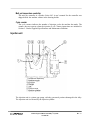
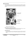
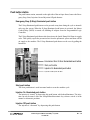
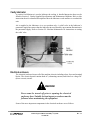
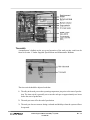
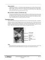
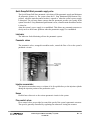
SECTION B1: MACHINE COMPONENTS
The machine portion of the Injected Metal Assembly system provides the means for:
•
holding, heating and injecting the alloy;
•
distributing and controlling electrical, pneumatic, coolant, drain, lubrication and gas
services;
•
holding and controlling the motion of the Cable Processor Module and tooling.
A brief description of the machine components will provide an understanding of the various
functions of the machine.
Control panel
CPM-1 Injected Metal Assembly™ System
ref 020718
B1-1
The control panel, mounted on the front of the electrical enclosure, houses
•
•
•
•
all push buttons and indicator lights
the operator interface module
the temperature controller
the cycle counter.
Note that individual push buttons and selector switches may vary depending on the termination
or small component assemblies being produced, and the operating sequence.
Push buttons
Alarm Reset illuminated push button
In the event that one of the limit or proximity switches fails during the cycle, the
Alarm Reset illuminated push button will illuminate. Pressing the Alarm Reset
illuminated push button will reset the alarm. When the light is illuminated, it
usually means that one of the switches failed to open. See Section G5: Troubleshooting for more information on how to determine which switch is not functioning correctly after the light illuminates.
Control On illuminated push button
Used to turn the Master Control Relay (MCR) on. The push button illuminates
when the MCR is on. The control power must be on to operate the system.
Ejector illuminated push button
Illuminates when the Ejector pneumatic valve is energised. May be used to
manually energise the valve in setup mode.
Head Close illuminated push button
Illuminates when the Cable Processor Module Close pneumatic valve is energised. May be used to manually energise the valve in setup mode.
Head Open illuminated push button
Illuminates when the Cable Processor Module Open pneumatic valve is energised. May be used to manually energise the valve in setup mode.
Lubricate illuminated push button
Illuminates when the Lubricate pneumatic valve is energised. May be used to
manually energise the valve.
Mechanism Retract/Advance illuminated push buttons
Illuminates when the Moving Mechanism pneumatic valve is energised. May
be used to manually advance/retract the moving mechanism in setup mode.
CPM-1 Injected Metal Assembly™ System
ref 020718
B1-2
Melt Pot On/Off selector switch
Used to turn the melt pot on and off. The selector switch is generally left in the
on position, and the time switch is used to energise the melt pot. The selector
switch must be in the on position during production.
Setup/Manual/Automatic key selector switch
Used to select the setup, manual or automatic mode.
In the setup position, the control panel illuminated push buttons may be used to
energise their respective pneumatic valves. The system will not cycle with the
selector switch in the setup position. The injection cannot be turned on in the
setup position.
In the manual position, the system control will allow individual system cycles
to be run using the Start push button.
In the automatic position, the system control will allow system cycles to be run
without depressing the Start push button. The cycle is started when the Cable
Processor Module Closed proximity switch closes.
CAUTION!
The key for the Setup/Manual/Automatic key selector switch
should not be left in the switch. Only authorized personnel
should have access to the key.
Torch Off push button
Used to turn the torch off.
Torch On illuminated push button
Used to turn the torch (nozzle heater) on. The torch must be lit manually with a
suitable device. The torch must be on and the air/gas mixture must be ignited
when the system is in production.
Operator Interface module
The operator interface module is used to access all Programmable Logic Controller functions. The status of inputs (ie. proximity switches, selector switches, push buttons, etc.),
outputs and internal status bits can be seen using the module. Timers can be adjusted using
the module, but the sequence of operation cannot be changed using the operator interface
module. A user’s manual for the module is inside the machine cabinet in the drawing holder.
CPM-1 Injected Metal Assembly™ System
ref 020718
B1-3
Melt pot temperature controller
The melt pot controller is a Watlow Series 965. A user’s manual for the controller was
shipped inside the machine cabinet in the drawing holder.
Cycle counter
The cycle counter indicates the number of injection cycles the machine has made. The
counter does not operate when the injection is off. Counter instructions are included in
Section J: Vendor Supplied Specifications and Maintenance Bulletins.
Injection unit
The injection unit is a piston type pump, with the gooseneck portion submerged in the alloy.
The injection unit is activated by the Injection cylinder.
CPM-1 Injected Metal Assembly™ System
ref 020718
B1-4
Gooseneck assembly
The gooseneck assembly consists of the injection sleeve pressed into the gooseneck casting.
Gooseneck
The gooseneck is a machined steel casting which holds the injection sleeve. A
threaded top section allows for the installation of the injection nozzle. A machined passage allows alloy to flow from the bottom of the injection sleeve to
the nozzle.
Injection sleeve
A stellite injection sleeve, pressed into the gooseneck, is accurately machined
to a close tolerance fit with the injection plunger. This close fit ensures that the
injection unit can develop adequate alloy pressure during the injection cycle.
Fill slot
The fill slot is machined in the injection sleeve and a corresponding hole is
machined in the gooseneck. This allows the injection unit to refill with alloy
between injection cycles.
Y-bracket
The Y-bracket, attached to the melt pot frame, supports the gooseneck assembly.
Plunger
The stellite plunger, driven by the injection cylinder, pumps the molten alloy from the
gooseneck assembly into the tool cavity. The close tolerance fit between the plunger and
the injection sleeve ensures that the injection unit can develop adequate alloy pressure
during the injection cycle.
Link
The link connects the plunger to the injection lever.
Injection lever
The injection lever couples the plunger to the Injection cylinder, allowing the plunger to be
advanced and retracted during the injection cycle.
Injection cylinder
The pneumatic Injection cylinder drives the plunger during the injection cycle.
Injection nozzle
The nozzle is seated in the gooseneck. It is the means by which alloy is transferred from the
pump to the tool. The end of the nozzle has a precision ground tip which seals on the nozzle
seat portion of the tool.
CPM-1 Injected Metal Assembly™ System
ref 020718
B1-5
Fill gap
With the plunger in its fully retracted position, the distance between the bottom of the
plunger and the bottom of the fill slot in the injection sleeve is referred to as the fill gap.
The fill gap is adjusted by moving the position of the clevis on the threaded end of the
injection cylinder rod. The fill gap is typically set at 1 mm (.040 inch).
Coolant supply and drain
There are two separate cooling circuits within the machine. One circuit cools the melt pot
frame, and another cools the tooling. Coolant supply and drain ports are located at the rear of
the machine.
Melt Pot frame cooling coil
The melt pot frame cooling coil prevents the exterior of the pot frame from becoming
excessively hot during machine operation. A needle valve, located under the parts tray, can
be used to restrict the coolant flow through the pot frame. This allows the majority of the
coolant to flow through the smaller diameter tool circuit coolant passages.
Tool coolant circuit
The tooling coolant is controlled by two valves on the left side of the machine. The coolant
flows through the base of the Cable Processor Module, to the fixed tool holder, then to the
movable tool and back to the drain.
Nozzle heater
The nozzle heater, also referred to as the torch or flame, is used to keep the nozzle at operating
temperature during operation of the IMA system.
Pneumatic regulator
A pneumatic regulator, located on the manifold inside the pneumatic compartment, allows
for adjustment of the nozzle heater air pressure.
Air and gas valves
Valves, for controlling the flow of air and gas to the nozzle heater mixing block, are located
inside the pneumatic compartment.
Mixing block
The nozzle heater air and gas supplies are combined in the mixing block, located on the left
side of the melt pot frame.
Adjusting valves
Needle valves regulate the proportions of air and gas delivered to the nozzle heater mixing
block.
CPM-1 Injected Metal Assembly™ System
ref 020718
B1-6
Twin torch tip
The twin torch tip directs the air/gas mixture to the base of the injection nozzle. Once
ignited, the flame maintains the nozzle temperature during operation of the IMA system.
Melt pot
The melt pot is a container which holds the molten alloy and keeps it at operating temperature.
Melt pot frame
The melt pot frame holds the melt pot assembly.
Melt pot assembly
The melt pot assembly, comprised of a number of individual components, provides the
means for holding and heating the alloy during operation of the IMA system.
Melt pot
The cast steel melt pot holds the reservoir of molten alloy.
Heating element
A 3500 watt heating element provides the means for melting the alloy and keeping it at operating temperature during production.
Thermocouple assembly
The thermocouple assembly, comprised of a protector tube and thermocouple, is immersed in
the alloy at the rear of the melting pot. It provides the means for measuring the temperature of
the alloy.
Protector tube
The steel protector tube holds the thermocouple, facilitating maintenance when the alloy is
not in the molten state.
Thermocouple
The thermocouple is the transducer used to measure the alloy temperature. The thermocouple is connected to the temperature controller via a connector plug, allowing for easy maintenance and replacement.
Ingot feeder (optional)
The optional ingot feeder automatically replenishes the alloy in the melt pot during production.
Alloy temperature fluctuations are minimized by using the ingot feeder, as it maintains a more
consistent temperature than is possible when manually replenishing the alloy.
CPM-1 Injected Metal Assembly™ System
ref 020718
B1-7
Moving mechanism
The pneumatically driven moving mechanism advances and retracts the Cable Processor Module on and off the injection unit nozzle. This movement allows the nozzle to be reheated between cycles so that molten alloy can pass quickly and easily through the nozzle at the time of
injection.
Moving mechanism and limit switch
Moving Mechanism Advanced limit switch
The Moving Mechanism Advanced limit switch signals the Programmable Logic Controller that the moving mechanism is fully advanced towards the nozzle.
Flow control valves
Two flow control valves are used to adjust the speed of the advance and retract motions of
the moving mechanism. The speed is controlled by regulating the exhaust air from the
cylinder.
CPM-1 Injected Metal Assembly™ System
ref 020718
B1-8
Linkage
The linkage transfers the motion from the moving mechanism cylinder to the yoke, on
which the Cable Processor Module is mounted. A tooth form, machined in the bottom
surface of the linkage, engages with the ratchet pin when the link pin, coupling the linkage
and lever, is removed. This engagement should physically prevent the moving mechanism
from fully advancing when the linkage and lever are disconnected.
Ratchet pin
The ratchet pin, mounted on the side of the moving mechanism mounting bracket, engages
with the tooth form on the linkage when the lever and the linkage are disconnected. This
engagement should physically prevent the moving mechanism from fully advancing when
the link pin, coupling the linkage and lever, is removed.
Link pin
The link pin connects the linkage to the lever. When the link pin is removed, the Cable
Processor Module can be tipped slightly back from the nozzle, facilitating maintenance of
the nozzle tip or removal of the hinge pin.
Hinge pin
The hinge pin connects the yoke to the Cable Processor Module. Removal of the hinge pin
allows the Cable Processor Module to be tipped well back from the nozzle, facilitating
maintenance of the nozzle tip and twin torch tip.
Hinge Pin-In-Place proximity switch
The proximity switch, mounted on the left-hand side of the moving mechanism, senses
whether the hinge pin is in place. The system will not cycle of the hinge pin is not correctly
installed.
CPM-1 Injected Metal Assembly™ System
ref 020718
B1-9
Push button station
The push button station, mounted on the right side of the melt pot frame, houses the Emergency Stop, Start, Injection On and Injection Off push buttons.
Emergency Stop (E-Stop) illuminated push button
The E-Stop illuminated push button can be pressed at any time during the cycle to immediately stop the system. When the E-Stop illuminated push button is activated, the Master
Control Relay (MCR) is turned off, disabling all outputs from the Programmable Logic
Controller.
The E-Stop illuminated push button also deactivates the Quick Dump/Soft Start air supply
valve. This quickly expels the pressurised air from the pneumatic system and shuts off the
air supply to the machine. The E-Stop illuminated push button can be reset by pulling the
button out.
Start push button
The Start push button is used in manual mode to start the machine cycle.
Injection On illuminated push button
The injection is “armed” by depressing this push button, which then illuminates. The injection can only be armed when the Setup/Manual/Automatic key selector switch is in the
manual or automatic positions.
Injection Off push button
The injection is “disarmed” by depressing this push button.
CPM-1 Injected Metal Assembly™ System
ref 020718
B 1 - 10
Cavity lubricator
A positive feed lubricator is used to lubricate the tooling. A detailed instruction sheet can be
found in Section J: Vendor Supplied Specifications and Maintenance Bulletins. Refer to this
instruction sheet for a detailed description of how the lubricator works and how to overhaul the
unit.
Air is supplied to the lubricator via a two-position valve. A relief valve in the lubricator’s
pneumatic supply line ensures that the lubricator in not affected by any transient fluctuations in
the pneumatic supply. Refer to Section G1: Machine Maintenance for instructions on setting
the relief valve.
Electrical enclosure
The electrical enclosure houses all of the machine electrics including relays, fuses and terminal
blocks. The electrical panel contains both AC (alternating current) and extra low voltage DC
(direct current) circuits.
WARNING!
Power must be turned off prior to opening the electrical
enclosure door. Suitable lockout/tagout procedures must be
followed when maintaining the equipment.
Some of the more important components in the electrical enclosure are as follows:
CPM-1 Injected Metal Assembly™ System
ref 020718
B 1 - 11
Time switch
A manufacturer’s bulletin on the set-up and operation of the melt pot time switch can be
found in Section J: Vendor Supplied Specifications and Maintenance Bulletins.
The time switch should be adjusted such that:
1. The alloy in the melt pot reaches operating temperature just prior to the start of production. The time switch is generally set to turn the melt pot on approximately two hours
before the start of production.
2. The melt pot turns off at the end of production.
3. The melt pot does not turn on during weekends and holidays when the system will not
be operated.
CPM-1 Injected Metal Assembly™ System
ref 020718
B 1 - 12
Main disconnect breaker
The main disconnect breaker is located in the top left corner of the electrical enclosure. The
breaker rating has been correctly specified for the machine. Under no circumstance should
the breaker be changed to a unit with a different rating.
Master Control Relay (MCR)
Virtually all machine functions are controlled through the MCR. It feeds the Programmable
Logic Controller outputs and the Quick Dump/Soft Start air supply valve.
The MCR is on when the Control On illuminated push button is illuminated. To turn the
MCR on, press the Control On illuminated push button. The E-Stop illuminated push button must be pulled out for the MCR to be turned on.
If the E-Stop illuminated push button is activated, the MCR is off, and the machine cannot
be operated. Resetting the E-Stop illuminated push button will turn the machine control
power back on.
Programmable Logic Controller (PLC)
Complete operating manuals for the Programmable Logic Controller are shipped with the
equipment.
Specific programming has been entered into the controller to accommodate Cable Processor Module tooling.
The program has been stored on an EEPROM (Electrically Erasable Programmable Read
Only Memory) chip inside the controller. When the main electrical breaker is turned off
and then back on, the Programmable Logic Controller automatically loads the program
from the EEPROM chip.
Fuses
Fuses for the various electric circuits are clearly labelled on the electrical panel. A fuse
schedule is affixed to the inside of the electrical enclosure rear door. Only fuses of the
correct rating should be used. Fuse ratings are clearly specified on the machine electrical
connection diagrams found in Section K: Machine Reference Drawings.
DC power supply
A 24 volt direct current (VDC) power supply is installed on the electrical panel. This device provides DC voltage for the control of the machine functions. Although the Programmable Logic Controller is powered by line voltage, all inputs and outputs are 24 VDC.
CPM-1 Injected Metal Assembly™ System
ref 020718
B 1 - 13
Surge protector
A surge protection device, or transient voltage surge suppressor, is used to filter the incoming line voltage. This device protects the various electrical components from voltage spikes
which could damage them. The unit is functioning correctly as long as the small, green
LED on the side of the surge protection device is on.
Melt pot heater contactor and solid state relay
A contactor and solid state relay are used to cycle power to the melt pot heater element and
are mounted on the electrical panel. The contactor closes whenever the melt pot is turned
on. The melt pot temperature controller then controls the status of the solid state relay in
order to maintain the correct melt pot temperature setting.
Pneumatic system
Air enters the machine through a manual shut-off valve. It travels through a filter, a pneumatic
lubricator and into a Quick Dump/Soft Start valve. From this valve, air enters two pressure
regulators - one for the stack or line pressure, and one for the injection pressure. There are two
pressure regulators built into the pneumatic stack. One is for the torch air, and one is for the
ejector. The rest of the pneumatic circuits operate at machine line pressure.
Filter
The pneumatic filter traps large particles before they can enter the pneumatic circuits. The
filter bowl drains automatically when the air supply to the machine is turned off.
CPM-1 Injected Metal Assembly™ System
ref 020718
B 1 - 14
Quick Dump/Soft Start pneumatic supply valve
The Quick Dump/Soft Start pneumatic valve shuts off the pneumatic supply and dissipates
all pneumatic pressure in the system when the E- Stop illuminated push button is depressed, when the main disconnect breaker is opened or when the system’s power supply
is disrupted. The soft start feature ensures that the pneumatic pressure rises gently in the
system when the E- Stop illuminated push button is reset, when the main disconnect breaker
is closed or
when the system’s power supply is re-established. This allows any pneumatic actuators to
slowly move to their home positions when the pneumatic supply is re-established.
Lubricator
The lubricator feeds lubricating oil into the pneumatic system.
Pneumatic valves
The pneumatic valves, arranged in modular stacks, control the flow of air to the system’s
pneumatic circuits.
Injection accumulator
The injection accumulator stores a volume of air for rapid delivery to the injection cylinder
during the injection portion of the production cycle.
Hoses
Flexible hoses direct air to the various pneumatic circuits in the system.
Flow control valves
Flow control valves are provided to control the speed of the system’s pneumatic actuators.
The speed is generally controlled by regulating the exhaust air leaving the actuator.
CPM-1 Injected Metal Assembly™ System
ref 020718
B 1 - 15
CPM-1 Injected Metal Assembly™ System
ref 020718
B 1 - 16