1
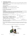
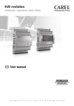
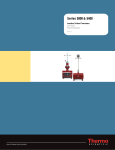
Cabinet Cooler Vortex Size 1 Handbook ML374 CONTENTS: 1. General Instructions 2. Specification 3. Certification Data 4. Application Suitability 5. Installation 6. Commissioning 7. Maintenance 8. Operational Testing 9. Fault Finding 10. Drawings and Documents ML374 V11 16/06/15 Page 1 of 6 1 GENERAL INSTRUCTIONS When a Cabinet Cooler is required all potential sources of heat generation should be taken into account. Example: When an enclosure is in direct sunlight installing a sun shade and possibly thermal insulation would reduce the solar heating considerably. If a Cabinet Cooler is required the following must be considered. Principle of Operation The Cabinet Cooler (Vortex type) works by using a compressed air supply and spinning the air into a chamber at very high RPM. This splits the air into a hot and cold fraction. The hot fraction of air is exhausted outside the enclosure. The cold fraction is vented into the enclosure and ultimately has to be vented out of the enclosure. 2 SPECIFICATION Power Supply: (as per model ordered) 110 Vac, 230 Vac 50/60Hz 24 Vdc AVC-0000-001 AVC-0000-003 3 110 Vac Version 24 Vdc Version Air Supply: 60 - 100 psi 4 - 7 barg 25scfm, 708Nl/min at 100psi, 7barg Maximum of 40ºC, 104ºF [For version with Tamb -20ºC to +40ºC] Maximum of 55ºC, 131ºF [For version with Tamb -20ºC to +55ºC] Cooling Capacity 300 W at 100psi, 7 barg Temperature Control: Electronic +/-2ºC, +/-3.6ºF Maximum Air Outlet Temperature 130ºC/ 266ºF Weight 1.5kg, 4lbs Hazardous Area T Class T4 or T3 at 55ºC, 131ºF or at 40ºC, 104ºF ambient (as ordered) When housed inside IP54/NEMA 4 enclosure or better. CERTIFICATION DATA Cabinet Vortex Coolers are certified under Declaration of Conformity EXPO 12ATEX1212X against EN13463-1:2009 Non-electrical basic methods and requirements. Vortex Coolers are suitable for use in Hazardous Areas where Equipment Group II Category 2G is required, when installed within a pressurized enclosure and the following instructions are adhered to. WARNING The device adjuster screw located beneath the air silencer (muffler) has been pinned to limit the maximum exit air temperature. Any un-authorised adjustment of the ‘slotted’ valve will automatically invalidate the use of this product in a hazardous area. After assembly of the Cabinet Cooler on to an Ex p, X, Y, or Z enclosure this Cooler/muffler must be replaced onto the exhaust of the Vortex Tube which is located in the Hazardous Area, in such manner that can only be removed by the use of a tool. It is responsibility of the user to ensure that the Cabinet Vortex Cooler is sufficiently earthed to the enclosure ensuring that any static charge created is discharged safety to the enclosure. ML374 V11 16/06/15 Page 2 of 6 4 APPLICATION SUITABILITY • • As the Cabinet Cooler displaces air care should be given on installations where movement of dust may be an issue, (Zone 21 & 22 or Class II). The following materials are used in the construction of Cabinet Cooler. If substances that will adversely affect any of these materials are present in the surrounding environment, please consult Expo Technologies for further guidance. Materials of construction: • Stainless Steel • Polyamide • Mild (carbon) Steel • Epoxy Resin • Brass • ABS • Copper • PVC • This equipment is designed for use under normal industrial conditions of ambient temperature, humidity and vibration. Please consult EXPO before installing this equipment in conditions that may cause stresses beyond normal industrial conditions. • The Cabinet Cooler is not silent in operation. 5 INSTALLATION General Notes When installing a Cabinet Cooler into a Pressurized Enclosure the following issues should be considered. • • • • • • • • • • • • For use in Zone 1 (Category 2) applications, the user shall ensure that the maximum regulator pressure, even under fault condition, does not exceed 7 barg. A second Relief Valve unit may be required to exhaust the cold fraction entering the Pressurized Enclosure. This second Relief Valve unit will need to be set at a higher lift off pressure than the Relief Valve unit supplied with the MiniPurge Control Unit. This is to ensure that the operation of the MiniPurge is not interfered with. The second Relief Valve unit must also be capable of exhausting the full flow rate of the cold fraction. This is typically between 20-80% of the air supply dependant on setting at time of commissioning. The MiniPurge must control the operation of the Cabinet Cooler by way of the purge complete signal. The MiniPurge must go through a purge cycle before the Cabinet Cooler receives either a supply of compressed air or electrical power. This will prevent the MiniPurge considering the cold fraction as the purge flow which would be incorrect. The solenoid valve will obtain its power once the purge time has elapsed. Cabinet Cooler assemblies supplied by Expo have a solenoid valve to control the compressed air supply. In addition a thermostatic control is included and a one way air valve fitted to the cold fraction. The one way air valve is to prevent the enclosure losing pressure when the Cabinet Cooler is not in operation. If a customer is to install a Cabinet Cooler themselves into an Expo Pressurized Enclosure that has already been certified by Expo then Expo requires; Documents, drawings, circuits etc, recording this addition so that we can issue an amendment to the overall certificate. This may incur additional costs. To install the Cabinet Cooler refer to the general assembly drawing for overall dimensions. Drill a hole on the top face of the enclosure, the one way valve must be vertical. It is possible to mount the Vortex tube in the side wall, although this is not the preferred option. Unscrew the hot air exhaust muffler and remove the gland. Fix gland into the drilled hole. Now insert the vortex tube through the gland and tighten the gland up to hold the Cabinet Cooler in place. ML374 V11 16/06/15 Page 3 of 6 • • • 6 Now replace the hot air exhaust muffler and place supplied label adjacent to the muffler on the outside of the enclosure. The temperature sensor can now be positioned within the enclosure. This could be on a specific device or in the top of the enclosure where the temperature will normally be at it’s greatest. The wiring and pneumatic pipe work can now be fitted. COMMISSIONING Always ensure that there is adequate exhaust and pressure relief provided for the enclosure. If this is not provided the enclosure will become over pressurized and may operate outside of its Test Pressure specification and possibly become a hazard in itself. General Notes Compressed air supply. The air supply temperature should not exceed 40ºC, 104ºF or 55ºC, 131ºF, depending on the model. Solar shading or thermal insulation of air supply pipe work may be required. Air supplies are plagued with condensed water vapour and droplets in the air lines. This condensation leads to rust and dirt in the air lines. Also, some compressors will allow oil or oil vapour to enter the air line. It is important that the electrical equipment within the Pressurized Enclosure is not contaminated. Small orifices within the Cabinet Cooler may become clogged with rust, dirt and water droplets. A 5 micron filter will separate 99% of foreign material from the air supply, allowing virtually maintenance free operation. The use of an oil filter with an effective filtration of 0.01 micron will remove the oil droplets for an even cleaner air supply. Keep in mind that the current line or hose might contain water, dirt or oil and should be blown out before installation. Also, pipe thread sealant or tape must be carefully applied to avoid clogging product orifices. When the temperature of the air inside the Cabinet drops to 0ºC, 32ºF, the water vapour in the air will start to freeze. If this poses a problem with ice clogging the orifices of the generator inside the tube, an air dryer must be used to lower the dew point to keep out the water vapour. An air dryer rated at -19ºC, 2ºF will produce a dew point low enough to eliminate the water vapour freezing in the orifices of the generator. • The installation of the electrical connections shall be inspected for correct installation before the unit is put into service. • The Cabinet Cooler has the temperature setting, factory set to 20ºC, 68ºF • If the customer wishes to change this then the adjustment resistor is shown on the drawing provided. This does not have an indexed scale. • The Cabinet Cooler can now be operated. Once a purge cycle has been completed the Cabinet Cooler will become active. As soon as the sensor detects the set temperature has been exceeded the Solenoid Valve will open and the Cabinet Cooler will operate. • Air will be vented from the Hot air Muffler and out of the enclosure Relief Valve. • The Solenoid Valve will close once the set temperature has been reached. 7 MAINTENANCE The Cabinet Cooler has no moving parts. Clean, compressed air moving through the tube will not cause wear on the parts and will provide the same service for an indefinite period of time. Occasionally, dirt, water or oil may enter the tube from the compressed air supply and hinder the performance. When this happens, simply take the unit apart, clean the parts, and reassemble, tightly replacing the cold end cap to properly seat the generator. The Solenoid Valve is also maintenance free and should be replaced if a fault does occur. ML374 V11 16/06/15 Page 4 of 6 8 OPERATIONAL TESTING This section describes the functionality test to ensure correct mechanical operation, wiring and electrical continuity. Warning: Do not open enclosure when an explosive atmosphere is present. Only carry out this test in a safe environment. • • • • • Equipment Required As a minimum requirement the following will be required. Vortex Cooler 110Vac, 250Vac or 24Vdc Power Supply (dependent on model) 7 bar Air supply. Hot source, e.g. hot water (temperature above +55 ºC). Calibrated thermometer (digital). Procedure Only complete the following procedure if trained and suitably skilled in the safe use and testing of 0-250V electrical equipment and pneumatic equipment rated up to 10barg. Ensure precautions are taken when dealing with the Heat produced by the Vortex Cooler (specifically the silencer/muffler) after testing • Ensure that all wires terminated properly. • Use hot water to heat the temperature sensor. It may be easier to temporally remove the temperature sensor, if convenient, from the enclosure wall. The vortex cooler will start to run when the temperature sensor exceeds 55 ºC. • After around one minute, if a temperature differential of more than typically 10 ºC can be measured at the Cold outlet, the vortex cooler can be considered working. • Finally, remove the temperature sensor from the hot water and once given sufficient time to cool, the vortex cooler flow will stop. Replace the temperature sensor back to its original position. • If the vortex cooler fails to start, consult Expo Technologies or your local representative. are connected and Hot exhaust (outside enclosure) Cold outlet (inside enclosure) Temperature sensor ML374 V11 16/06/15 Page 5 of 6 9 FAULT FINDING • • • • • 10 The most common fault is a lack of air supply due to either low air supply pressure or poor flow rate. Poor flow is because of too small pipe work, long pipe lengths or small fittings. Occasionally dirty or very wet air causes ice build up within the enclosure, leading to intermittent operation and water within the enclosure. If the system does not work at all check the fuse has not blown. Ensure the temperature setting has not been tampered with. Ensure the air exhausts are not blocked. DRAWINGS AND DOCUMENTS TITLE Cabinet Cooler Assembly Cabinet Cooler Assembly ATEX Declaration of Conformity Drawing Number AVC-0000-001 AVC-0000-003 EXPO 12ATEX1212X ML374 V11 16/06/15 Page 6 of 6 48 21 IN V O R T EX T U B E D R 'W N C H K' D A P P 'D DRA W ING S T A T U S : A P P R OV E D : DA T E : MO D . N o : IS S UE : T O LE R A N C E S 2 D E C P L A C E ± 0 .1 1 D E C P L A C E ± 0 .2 N O D E C P L AC E ± 0 .5 FI N I S H MA T E R I A L G LAN D N U T A N D W A S H ER G L A ND ( P R ES S U R I Z ED ) S AF E AR E A E NC L O S U R E W ALL HAZA R DO U S AR E A L ED ( O N / O F F ) 1 2 J O B No: T IT L E C U S T OM E R : E x p o T e c h n o l o g i e s L im i t e d 3 O FF 1 / 4 " B S P P O R T S A NT I - T A M P E R P I N T B1 O U T P U T S O L EN O I D S O L E NO I D VALVE F FV T EM P ER A T U R E S EN S O R a r e t h e y to b e u s e d in a n y w a y a g a in s t o u r i n t e r e s t s . P O W ER S U P P L Y A ND C O NT R O L LE R H O T A I R EX H A U S T M U F F L ER 1 9 4 [7 5 /8 " ] Exp o T e c h n o l o g i e s L i m i te d . T h e y a r e t o b e t r e a t e d a s c o n f id e n t i a l a n d a r e r e tu r n a b l e F U S E 1 6 0 m A 2 5 0 V IEC 1 2 7 TB2 1 1 0 O R 2 3 0 Va c 5 0 /6 0 H z C O NT R O LL E D V I A P U R G E S Y S T EM U N IT E D K IN G D O M SU R R EY KT7 0 R H S HE E T N o. DR A W ING N o. SC ALE O F T O T H E C A B I NE T C O O L E R O N T H E EN T R Y F A C E O F T H E P R E S S U R I Z E D E NC L O S U R E S U P P L I ED W I T H L A B E L M L A - Z D W 0 - 0 1 2 . T H IS L A B EL M U S T B E A T T A C H E D A D JA C E NT N O T ES T E M P E R A T U R E S E T T I NG ( C L O C K W I S E T O I N C R E A S E S ET P O I N T ) E N L 2 W I R E S 1 m L O NG T W I S T E D . u p o n r e q u e s t. T h e y a r e n o t to b e c o p i e d o r c o m m u n i c a t e d in p a r t o r i n w h o le w it h o u t w r i tt e n c o n s e n t f r o m E x p o T e c h n o l o g i e s L i m i te d , n e i th e r T h e c o n te n ts o f t h i s d r a w in g / d o c u m e n t a r e C o p y r i g h t S O L EN O I D V A LV E F L A T N E S S T O B E L E S S T H A N 0 .4 m m O V E R A N Y 1 0 0 m m L E N G T H 8 9 [ 3 1 / 2 "] E NC L O S U R E W A L L HO LE D O NO T S C A L E O NE W A Y V A L V E F O R C O L D A I R . G R A V I T Y O P ER A T ED - M U S T A L W A Y S B E V ER T I C A L 1 5 0 [ 5 7 / 8 "] P R O J E C T I ON [ 1 7/ 8 " ] 1 1 9 [4 1 1 /1 6 " ] U N S P E C IF I E D A DJU ST AB LE D I M E N S IO N S I N m m 2 1 7 [8 9 /1 6 " ] 3 rd A N G L E V ER T I C A L 48 21 IN V O R T EX T U B E D R 'W N C H K' D A P P 'D DRA W ING S T A T U S : A P P R OV E D : DA T E : MO D . N o : IS S UE : T O LE R A N C E S 2 D E C P L A C E ± 0 .1 1 D E C P L A C E ± 0 .2 N O D E C P L AC E ± 0 .5 FI N I S H MA T E R I A L G LAN D N U T A N D W A S H ER G L A ND A NT I - T A M P E R P I N L E D ( O N /O F F ) J O B No: T IT L E C U S T OM E R : E x p o T e c h n o l o g i e s L im i t e d ( P R ES S U R I Z ED ) S AF E AR E A E NC L O S U R E W ALL HAZA R DO U S AR E A T B1 1 2 O U T P U T S O LE NO I D S O L E NO I D VALVE F FV T EM P ER A T U R E S EN S O R a r e t h e y to b e u s e d in a n y w a y a g a in s t o u r i n t e r e s t s . P O W ER S U P P L Y A ND C O NT R O L LE R H O T A I R EX H A U S T M U F F L ER 1 9 4 [7 5 /8 " ] Exp o T e c h n o l o g i e s L i m i te d . T h e y a r e t o b e t r e a t e d a s c o n f id e n t i a l a n d a r e r e tu r n a b l e F U S E 1 6 0 m A 2 5 0 V IEC 1 2 7 TB2 2 4 V d c C O NT R O L L E D V I A P U R G E S Y S T EM U N IT E D K IN G D O M SU R R EY KT7 0 R H S HE E T N o. DR A W ING N o. SC ALE O F T O T H E C A B I NE T C O O L E R O N T H E EN T R Y F A C E O F T H E P R E S S U R I Z E D E NC L O S U R E S U P P L I ED W I T H L A B E L M L A - Z D W 0 - 0 1 2 . T H IS L A B EL M U S T B E A T T A C H E D A D JA C E NT N O T ES T E M P E R A T U R E S E T T I NG ( C L O C K W I S E T O I N C R E A S E S ET P O I N T ) + 2 W I R E S 1 m L O NG T W I S T E D . u p o n r e q u e s t. T h e y a r e n o t to b e c o p i e d o r c o m m u n i c a t e d in p a r t o r i n w h o le w it h o u t w r i tt e n c o n s e n t f r o m E x p o T e c h n o l o g i e s L i m i te d , n e i th e r T h e c o n te n ts o f t h i s d r a w in g / d o c u m e n t a r e C o p y r i g h t S O L EN O I D V A LV E F L A T N E S S T O B E L E S S T H A N 0 .4 m m O V E R A N Y 1 0 0 m m L E N G T H 8 9 [ 3 1 / 2 "] E NC L O S U R E W A L L HO LE D O NO T S C A L E O NE W A Y V A L V E F O R C O L D A I R . G R A V I T Y O P ER A T ED - M U S T A L W A Y S B E V ER T I C A L 1 5 0 [ 5 7 / 8 "] P R O J E C T I ON [ 1 7/ 8 " ] 1 1 9 [4 1 1 /1 6 " ] U N S P E C IF I E D A DJU ST AB LE D I M E N S IO N S I N m m 2 1 7 [8 9 /1 6 " ] 3 rd A N G L E V ER T I C A L (1) Declaration of Conformity (2) Expo Technologies Document Number EXPO 12ATEX1212X/1. (3) This declaration is issued for the electrical apparatus: Cabinet Vortex Coolers Models AVC-0000-### (4) Manufacturer Expo Technologies Ltd Surrey KT7 0RH UK (5) This electrical apparatus and any acceptable variation thereto is specified in the Annex to this certificate and the documents therein referred to. (6) This declaration and schedule confirms compliance of each unit with the following standards: EN 13463-1:2009 Non electrical basic methods and requirements (7) This apparatus fulfils all the requirements for Group II Category 2 equipment in accordance with European Directive 94/9/EC. (8) The design is documented in Expo Technologies Technical Construction File number SC30 and Intertek Reference G100975170 (9) The apparatus marking: II 2G T4 or T3 Tamb -20ºC to +40ºC or II 2G T4 or T3 Tamb -20ºC to +55ºC For and on behalf of Expo Technologies Ltd. Thames Ditton, 21th November 2012 Sarah Wickson Certification Engineer Page 1 of 3 Expo Technologies Ltd. Registered in England No2854600 Expo Technologies Ltd Summer Road, Thames Ditton, Surrey KT7 0RH, UK T +44 (0)20 8398 8011 F +44 (0)20 8398 8014 E [email protected] www.expoworldwide.com Annex to Declaration of Conformity EXPO 12ATEX1212X/1 10) Description The Expo Technologies Cabinet Vortex Cooler provides cooling for enclosures using compressed air. Cooling may be required either to remove heat generated by the contents of the enclosure, or to compensate for high ambient temperatures. There are two types of Cabinet Vortex Coolers. Models AVC-0000-001, AVC0000-002 & AVC-0000-003 have been designed for use in Zone 1 and Zone 2 (Categories 2 and 3), Group IIC applications in Enclosures protected by Pressurization types ‘px’, ‘py’. or ‘pz’. Models AVC-0000-006, AVC-0000-007 & AVC-0000-012 have been designed for use in Zone 2 (Category 3) applications and has been assessed as Ex nA mc IIC (refer to EXPO 09ATEX1122X). The Cabinet Vortex Cooler is provided with a solenoid valve and a temperature sensor. 11) Specification Air supply 4 - 7 barg Supply voltage 110 - 230 Vac or 24 Vdc Cooling capacity 400W or 1500W @ 7 barg Ambient temperature range –20ºC to + 40ºC or –20ºC to +55ºC as marked on the equipment. 12) Special conditions of safe use The device adjuster screw located beneath the air silencer (muffler) has been pinned to limit the maximum exit air temperature. Any alteration will invalidate this certificate. The maximum supply air temperature shall not exceed 40ºC or 55ºC depending on the model. The Cabinet Vortex Cooler must be installed to conform to the instructions in the user manual. Measures shall be taken to limit the enclosure pressure to safe levels. Once the Cabinet Vortex Cooler is installed, the silencer (muffler) shall be fixed onto the unit so that it can only be removed by the use of a tool. It is responsibility of the user to ensure that the Cabinet Vortex Cooler is appropriately earthed to the enclosure. For use in Zone 1 (Category 2) applications, the user shall ensure that the maximum regulator pressure, even under fault condition, does not exceed 7 barg. 13) Hazards identified The hazard presented by hot gases released into the potentially explosive atmosphere and hot metallic surfaces on the Cabinet Vortex Cooler are prevented by limiting the unit for use in a specific T Class, as marked on the label of each unit. Page 2 of 3 Expo Technologies Ltd. Registered in England No2854600 Expo Technologies Ltd Summer Road, Thames Ditton, Surrey KT7 0RH, UK T +44 (0)20 8398 8011 F +44 (0)20 8398 8014 E [email protected] www.expoworldwide.com Annex to Declaration of Conformity EXPO 12ATEX1212X/1 (13) Hazards identified (Continuation) The hazard presented by potential electrical sparks that could escape into the potentially explosive atmosphere through the Vortex tube is prevented by a tortuous path of minimum two 45 degree bends. Additionally, the silencer (muffler) may have double brass mesh which prevents the discharge of metal chips, abrasive grits, dusts and other contaminates. Due to the movement of air through the Cabinet Vortex Cooler static electricity could be produced and ignite the potentially explosive atmosphere. A special condition of safe use for this certificate states the user shall ensure the Cabinet Vortex Cooler is sufficiently earthed to the enclosure ensuring that any static charge created is discharged safety to the enclosure. 14) Documentation Description AVC-0000-001 General arrangement AVC-0000-002 General arrangement AVC-0000-003 General arrangement AVC-0000-006 General arrangement AVC-0000-007 General arrangement AVC-0000-012 General arrangement Document number AVC-0000-001 AVC-0000-002 AVC-0000-003 AVC-0000-006 AVC-0000-007 AVC-0000-012 Test Procedures & User Manuals Test Procedure – Cabinet Cooler (Tamb +40ºC) Test Procedure – Cabinet Cooler (Tamb +55ºC) Size 1 Cabinet Vortex Cooler Size 2 Cabinet Vortex Cooler Size 1 Ex nA Cabinet Vortex Cooler 15) Issue 6 2 2 3 2 1 Date 14/12/11 13/1/09 14/12/11 12/10/12 12/05/09 9/10/12 Number TP-518-031-WD TP-518-090-WD ML374 ML471 ML463 Certificate History Issue Date 0 10 September 2012 1 21 November 2012 Page 3 of 3 Expo Technologies Ltd. Registered in England No2854600 Comment Initial release of certificate Introduction of the following variations: Extra models included (Ex nA models) T3 Temperature Class permitted Expo Technologies Ltd Summer Road, Thames Ditton, Surrey KT7 0RH, UK T +44 (0)20 8398 8011 F +44 (0)20 8398 8014 E [email protected] www.expoworldwide.com With European Directives Declaration of Conformity Expo Technologies Ltd Hanworth Road Sunbury on Thames TW16 5DB UK This document confirms that Cabinet Coolers manufactured by Expo Technologies Ltd conform, as described, to the following European Directives and standards:- 89/336/EEC Electromagnetic Compatibility Directive 73/23/EEC Low Voltage Directive 97/23/EC Pressure Equipment Directive Signed Managing Director S:\Files\QA\CERTS\C-OF-C\Cabinet Cooler CE SC007 V2.doc Date 02/01/2013 Confidential Assessment file reference SC007 Expo Technologies Ltd. Unit 2, The Summit Hanworth Road Sunbury on Thames TW16 5DB Tel Fax E-mail: + 44 (0) 20 8398 8011 + 44 (0) 20 8398 8014 [email protected] Expo Technologies Inc. 9140 Ravenna Road Unit #3 Twinsburg OH 44087 USA Tel: Tel: Fax: E-mail: +1 888-NFPA-496 +1 (440) 247 5314 +1 (330) 487 0611 [email protected] www.expoworldwide.com