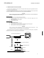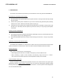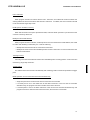
1
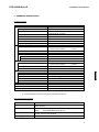
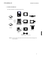
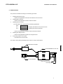
RTE-V850E/MA1-IE
Hardware User's Manual
RealTimeEvaluator
RTE-V850E/MA1-IE
Hardware User's Manual
REVISION HISTORY
Rev. 1.0
December 3, 1999
1st edition
Rev. 1.1
October 20, 2000
Clerical error correction
Tron command, …
1
RTE-V850E/MA1-IE
Hardware User's Manual
CONTENTS
1. INTRODUCTION .............................................................................................................. 3
2. MAIN FEATURES............................................................................................................ 4
3. HARDWARE SPECIFICATION.......................................................................................... 5
4. SYSTEM CONFIGURATION ............................................................................................. 6
5. INSTALLATION................................................................................................................ 7
6. SETTING THE DIP SWITCH ............................................................................................. 8
7. DISPLAY LED................................................................................................................. 8
8. CONNECTING WITH THE USER SYSTEM ........................................................................ 9
Switching power on............................................................................................................................................... 9
Switching power off............................................................................................................................................... 9
9. PRECAUTIONS ............................................................................................................. 10
Precautions for connecting the user system .................................................................................................10
Handling the RTE-V850E/MA1-IE.....................................................................................................................10
Confirming connection with the host system .................................................................................................10
External clock input.............................................................................................................................................10
Cautions related to delay time..........................................................................................................................10
HALT instruction ..................................................................................................................................................11
ROM space in emulation memory ...................................................................................................................11
Breakpoint and break address .........................................................................................................................11
Time tag for trace.................................................................................................................................................11
Trigger setting......................................................................................................................................................11
Break operation on two instructions executed simultaneously..................................................................11
NQPACK set consumables ...............................................................................................................................12
2
RTE-V850E/MA1-IE
Hardware User's Manual
1. INTRODUCTION
The RealTimeEvaluator-V850E/MA1-IE (hereafter called the RTE-V850E/MA1-IE) is an in-circuit
emulator for the NEC RISC microcomputer V850E/MA1.
Using a dedicated emulator chip in the
RTE-V850E/MA1-IE has made it highly transparent, compact, and lightweight.
The RTE-V850E/MA1-IE is supported by two debug monitors, GHS's Multi and Midas's PARTNER.
Users can select either debug monitor according to the operating environment of their system.
The host system for the RTE-V850E/MA1-IE must be the PC98 series or DOS/V machine that has the
environment in which either of the debug monitors mentioned above can run. The host system and the
RTE-V850E/MA1-IE are connected via the interface card for a dedicated PCMCIA card or for the desktop
machine.
The RTE-V850E/MA1-IE is supposed to come with the following items. Make sure that you received all
these items.
1. RTE-V850E/MA1-IE main unit : One each
2. RTE for Win32 setup disk
: One each
3. User's manual
: One each
4. Grounding clip
: One each
5. RTE-PS03 power supply unit : One each
6. NQPACK set
: One each
In addition to the above items, the following are required in using the RTE-V850E/MA1-IE. They are not
standard accessories.
7. Interface kit (interface card and cable set) selected from:
• PC card interface kit
• PC98 desktop PC interface kit
• DOS/V desktop PC interface kit
• PCI bus interface kit
8. Debugger selected from:
• GHS C + Multi + Midas server
• PARTNER
3
RTE-V850E/MA1-IE
Hardware User's Manual
2. MAIN FEATURES
One of two source-level debuggers can be selected.
Users can select either high-level language debugger, Multi of Green Hills Software (GHS) or
PARTNER of Midas.
GHS's Multi supports seamless debugging in an C/C++ integrated environment.
Meanwhile,
PARTNER supports the C language of both GHS and NEC (CA850), allowing users to set up the tool
environment as they like.
Both debuggers are provided with sufficient functions as a high-level language debugger. Simply
clicking the mouse on the source enables running programs, setting break points, and inspecting
variables.
Highly transparent emulation functions are provided.
Use of a dedicated emulation chip in the RTE-V850E/MA1-IE enables controlling emulation without
using functions in the V850E/MA1. Almost all signal lines can be connected directly to the chip. As a result,
the emulation functions are provided with both functionally and electrically high transparency.
The standard configuration provides a sufficient emulation memory capacity.
The standard memory configuration of the V850E/MA1-IE matches the ROM and RAM internal to the
V850E/MA1, and the 4 Mbytes of emulation memory external to the V850E/MA1.
A realtime trace function is provided.
The RTE-V850E/MA1-IE has a realtime trace function useful in debugging a built-in system. The
realtime trace function can trace 32K cycles of any types including internal memory access cycles, as
driven by events.
A dedicated communication card is available for communication with the host.
Four different communication cards and a LAN interface are available. For machines that have card
slots, the Type-2 PC card that conforms to the PCMCIA Ver2.1/JEIDA Ver4.2 standard is used. For desktop
machines, the C bus card is used in the PC98 series, while the ISA or PCI bus card is used in PC-AT
compatible machines. When connecting to the host through a LAN, use the LAN-BOX.
4
RTE-V850E/MA1-IE
Hardware User's Manual
3. HARDWARE SPECIFICATION
Emulation section
Target device
Emulation function
Clock frequency
Clock source (main clock)
Internal ROM emulation capacity
Internal RAM emulation capacity
External memory emulation capacity
External memory mapping unit
Memory mapping type
Break function
Event setting
Step break
Manual break
Fail-safe break
Write protection
Guard area
Trace function
Event setting
1.
50 MHz
Automatic switching between external and internal
clocks (internal: 50 MHz)
512 KB (max)
60 KB (max)
4 MB
1 MB
RAM, ROM, GUARD, USER
Execution address condition :
4 points
Access cycle condition
: 4 points
Available
Available
Available
Available
Trace memory
Trace delay
Time measurement function
Measurement start
Measurement stop
Resolution
Maximum measurement time
Number of functions
Internal RAM realtime display
Pin mask function
Bus timeout function
Voltage operating range
Remarks
V850E/MA1 (LQFP-144)
Execution address condition :
2 points
Access cycle condition
: 3 points
166 bits x 32K words
0-7FFFh
At the beginning of execution
Till the occurrence of a break
1 CPU clock cycle
232 CPU clock cycles
1 ch
1 KB
RESET-, NMI, WAIT-, HLDRQAvailable
3.3 V
For external emulation memory, two wait cycles are forcibly inserted.
2. External emulation memory cannot be used with an 8 -bit bus.
Host and interface sections
Item
Target host machine
Debug monitor
Interface
Power supply
Description
PC-98 series
DOS/V machine
Green Hills
: Multi (Windows95)
Midas
: PARTNER (Windows95, 98, NT)
PC card Type-2 (PCMCIA Ver2.1/JEIDA Ver4.2 or higher), C bus,
ISA bus, PCI bus, and LAN-BOX
Dedicated AC adapter: RTE-PS03 (input = 100 V and output = +5 V, 3.5 A)
5
RTE-V850E/MA1-IE
Hardware User's Manual
4. SYSTEM CONFIGURATION
The system configuration of this product is shown below.
PC98 interface card
PC98 series
Power supply
PARTNER/Win
PC-AT or compatible
PC-AT interface card
(ISA and PCI)
RTE-xxxx-IE main unit
GHS Multi
NQ pack set
PC interface card
HRS
Note PC
Cable
(accompanying the interface card)
Remark Each PC system must be able to offer an environment in which the debugger to be
used can operate.
6
RTE-V850E/MA1-IE
Hardware User's Manual
5. INSTALLATION
The product is installed according to the following procedure.
1.
Installing the interface card
→ Refer to the applicable manual for the interface card to be used.
2.
Installing RTE for Win32
3.
Initializing RTE for Win32
→ Refer to the applicable manual for RTE for Win32.
(1) Start chkrte2.exe, and initialize the following parameters.
RTE
: V850E/MA1-IE
I/F-1
:
<<Specify the interface card you want to use.
I/F-2
:
<<Specify an IO port as required.
→ Refer to the applicable manual for RTE for Win32 for details.
4.
Installing the debug monitor
→ Refer to the applicable manual for the target monitor.
5.
Connecting with the user system
→ See Section 8 in this manual.
The setup of this system (exemplifying use of the PC card) is shown below.
Dedicated AC adapter
RTE-V850E/MA1-IE main unit
SW2
SW1
PC card interface
User interface section
Grounding clip
7
RTE-V850E/MA1-IE
Hardware User's Manual
6. SETTING THE DIP SWITCH
A switch at the front of the RTE-V850E/MA1-IE is used to specify the emulation mode. SW1 should be
set according to the configuration of the user system. SW1 is an eight-contact switch while SW2 is a
four-contact switch. All contacts of SW2 should be set to OFF.
SW1
Symbol
1
MODE0
2
MODE1
3
MODE2
Function
Initial value
Used to specify the CPU default mode
ON
[MODE2, MODE1, MODE0]
OFF
Romless mode0
:
[ ON , ON
, ON ]
ON
Romless mode1
:
[ ON , ON
, OFF ]
Single mode0
:
[ ON , OFF , ON ]
Single mode1
:
[ ON , OFF , OFF ]
4
Factory use
Always ON
ON
5
Factory use
Always ON
ON
6
Factory use
Always ON
ON
7
CKSEL
Used to specify the CPU clock operation mode
ON
ON: PLL mode, OFF: Direct mode
8
CLKINT
Used to switch the clock supplied to the CPU
OFF
ON: Internal clock, OFF: Auto select
[MODE2, MODE1, MODE0]
Specify the CPU mode used when the debugger starts with the user system not connected.
When a target is connected, the mode specified by the target mode pin is used.
[CKSEL]
Specifies the clock operation mode used when the user system is not connected. When a target
is connected, the mode specified by the target CKSEL pin is used.
[CLKINT]
Switches the clock supplied to the CPU.
OFF : When the user system is connected, the system clock is supplied. Otherwise, the
internal clock is used.
ON : The internal clock is always used. (The internal clock frequency is 5 MHz.)
[Factory use]
This contact should be always set to ON.
7. DISPLAY LED
The following LEDs are on the side of the main unit.
POWER : Lights when the RTE system power is on.
USER
: Lights when power is supplied to the user system.
RUN
: Lights when a user program is running.
8
RTE-V850E/MA1-IE
Hardware User's Manual
8. CONNECTING WITH THE USER SYSTEM
Connect the RTE-V850E/MA1-IE with a personal computer while referring to the applicable manual for
the interface kit used between them.
To connect the RTE to the user system, first install its accompanying NQPACK in the user system while
referring to the NQPACK technical document, then connect the RTE-V850E/MA1-IE.
[Caution]
Before connecting the CPU section, attach a grounding clip leading to the RTE-V850E/MA1-IE
main unit to a signal ground of the user system.
Switching power on
1. Switch on power to the host personal computer.
2. Connect a power supply dedicated to the RTE to the power supply jack of the
RTE-V850E/MA1-IE.
3. Switch on power to the user system.
4. Start the debug monitor.
Switching power off
1. Exit the debug monitor.
2. Switch off power for the user system.
3. Remove the power cord from the RTE-V850E/MA1-IE power supply jack.
4. Switch off power for the host personal computer.
[Caution]
When connecting the RTE-V850E/MA1-IE to the user system, take care about pin 1. If the
connection is incorrect, all connected devices may get damaged.
The following figure shows how the RTE-V850E/MA1-IE is connected to the user system. For details of
the NQPACK, refer to its accompanying technical document.
1 pin
V850E/MA1
Tip of the RTE-V850E/MA1-IE
Type-F YQ socket
YQ pack guide screw
To a ground
YQ pack
Solder
NQ pack
User system
9
RTE-V850E/MA1-IE
Hardware User's Manual
9. PRECAUTIONS
This section summarizes the precautions you should observe when using the RTE-V850E/MA1-IE.
Precautions for connecting the user system
1)
The RTE system cannot operate with the user system turned off. Leaving it in this state may damage
the user system.
2)
After the user system power is switched off, if you want to continue using the RTE system, basically
restart it from scratch. Otherwise, the RTE system may hang up.
3)
If the CPU in the user system fails to operate normally (because, for example, a reset is active or the
wait line is at a wait level), the RTE system may also fail to start up or may hang up with specific
commands.
Handling the RTE-V850E/MA1-IE
1)
Do not allow the exposed socket pins at the bottom of the RTE tip come into contact metals when they
are energized. Doing so may damage the unit.
2)
Do not fold the flexible board of the RTE tip or bend it through more than 90°. Doing so may break a
wire.
Confirming connection with the host system
Immediately after installation, run chkrte2.exe to select and set up the host interface card and RTE
system, then perform connection tests. Refer to the RTE for Win32 Installation Manual for details.
External clock input
When using an external clock, note the following.
* When supplying the clock from an oscillator, the frequency must be 30 MHz or less.
* When connecting a crystal or other resonator, the frequency range must be 2 to 12 MHz.
The constant of the external capacitor must be adjusted according to the resonator.
Cautions related to delay time
Almost all signals are connected directly between the CPU in the RTE and the user system (see
Appendix B). However, a delay of about 3 ns (typical) may occur due to the wiring length required in getting
to the tip and the capacity, compared with direct CPU connection. The user system must be designed so
as to accommodate this delay.
10
RTE-V850E/MA1-IE
Hardware User's Manual
HALT instruction
When program execution is broken with the HALT instruction, the address at the time matches the
starting address of the next instruction after the HALT instruction. In addition, the HALT instruction should
not be executed in single-step mode.
ROM space in emulation memory
When data is written to the space specified for ROM, a fail-safe break operation is performed but the
contents of memory will be lost.
Breakpoint and break address
When program execution is broken, if a break point is set to two less than the break address, the actual
PC value after breaking is reduced by two. Note the following.
* Breakpoints should not be set for consecutive instructions.
* Breakpoints should not be set immediately before the HALT instruction or branch instructions that
branch to themselves.
Time tag for trace
A time tag cannot be used with the first instruction immediately after a starting position. It also cannot be
used during single-step execution.
Trigger setting
The address of the first instruction immediately after a starting position cannot be specified as a trigger
point.
Break operation on two instructions executed simultaneously
* Single-step execution is broken after the two instructions are executed.
* If a break point is set in the ROM area for the latter instruction of the two that are executed
simultaneously, the program execution is broken at the next instruction.
* If a break points is set for the latter instruction of the two that are executed simultaneously and
program execution is started at the former instruction, the execution is not broken.
11
RTE-V850E/MA1-IE
Hardware User's Manual
NQPACK set consumables
(1)
144-pin type-F YQ socket
YQS-144SDF
(2)
144-pin YQ pack
YQP-144SD with guide screws
(3)
144-pin NQ pack
NQP-144SD
[Remark]
The sockets shown above are consumables. They should be replaced regularly, for example
after about 50 cycles of insertion/removal. However, a soldered socket at the lower surface of
the RTE-V850E/MA1-IE cannot be replaced. If it is expected that it is subjected to frequent
insertion/removal, install a 144-pin YQ socket previously for protection purposes.
12
RTE-V850E/MA1-IE
Hardware User's Manual
- Memo -
RTE-V850E/MA1-IE Hardware User's Manual
M921MNL02
13