1
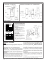
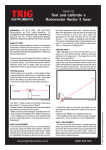
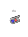
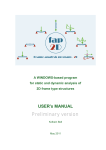
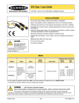
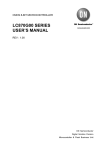
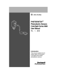
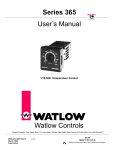
MULTI-BEAM®
Optical Data
Transmitter System
EM3T-1M Emitter and R1T3 Receiver
The MULTI-BEAM Optical Data Transmitter System provides a simple and very economical method for transmitting logic-level data over a modulated LED light beam. It
is ideal for communication with overhead cranes and other rail-mounted control
systems. It is also often used to carry data to or from rotary index tables, and in such
applications replaces mechanical brush contacts.
The data transmitter consists of a special MULTI-BEAM emitter scanner block (model
SBEM3) and dc power block (model PBT-1M). Emitter assembly model EM3T-1M
uses a modulated infrared LED that is gated "on" and "off" by the data signal via an
optical coupler in the power block. The light is inhibited (turned "off") when current is
applied to the optical coupler.
The data receiver (model R1T3) is composed of standard MULTI-BEAM components:
scanner block SBR1, power block PBT, and on/off logic model LM3. The output is an
open-collector NPN transistor that "follows" the action of the data stream. The LIGHT/
DARK operate jumper on the logic module may be used to program the output so that
a logic "1" is represented by the presence or absence of the light signal from the emitter.
A PNP (current sourcing) output is available by substituting power block model PBP,
or by ordering assembled receiver model R1P3. See the specifications and hookup
diagrams for 3- & 4-wire dc power blocks (data sheets 03499) for detailed information.
Data may be transmitted over a distance of up to 200 feet (60 m) in a clean environment
(see excess gain curve). The data rate (BAUD rate) is limited by the modulation
frequency (30 kHz) and by the receiver response. The R1T3 receiver will respond to a
change in data state (light or dark) of 1 millisecond or longer, resulting in a theoretical
maximum data rate (assuming a square wave) of 500 BAUD. This suggests a maximum
practical data rate of 300 BAUD. The receiver scanner block may be modified for 300
microsecond (3 times faster) response. Contact the factory for further information.
The MULTI-BEAM Optical Data Transmitter System is also used in conjunction with the Banner
model MP-8 Multiplexer Module for multiplesensor arrays used for profile measurement and
"curtain of light" applications. See data sheet
03421 for further information.
SPECIFICATIONS, Optical Data Transmitter System
SUPPLY VOLTAGE: 10 to 30V dc, 10% maximum ripple.
EM3T-1M 100mA maximum; R1T3 30mA maximum, exclusive of load.
INPUT SIGNAL: the input consists of the LED portion of an optical coupler. NOTE:
a suitable series resistor (customer supplied) must be installed to limit current to
betweeen 10 and 30mA dc. When current is applied to the LED, the 30kHz carrier is
inhibited.
OUTPUT CONFIGURATION: open-collector NPN transistor (sinks current to
negative side of supply), 250mA maximum. On-state voltage drop less than 1V dc; offstate leakage current less than 10 microamps.
RESPONSE TIME: 1 millisecond ON and OFF. Maximum data rate: 300 BAUD.
INDICATOR LED: red LED on top of R1T3 receiver. Banner's exclusive, patented
Alignment Indicating Device (AID™) lights the LED whenever the receiver detects the
light from the EM3T-1M, and pulses the LED at a rate proportional to the received light
level. It will go "off" with current applied to the modulator input.
CONSTRUCTION: same as standard MULTI-BEAMs. Reinforced VALOX® housing with components totally encapsulated. Stainless steel hardware. Meets NEMA
Functional Schematic and Hookup Information
standards 1, 3, 12, and 13.
OPERATING TEMPERATURE RANGE:
-40 to +70 degrees C (-40 to +158 degrees F).
RANGE: 200 feet (60m). See excess gain curve,
page 2.
WARNING
!
This photoelectric sensing system does NOT
include the self-checking redundant circuitry
necessary to allow its
use in personnel safety applications. A
sensor failure or malfunction can result in
either an energized or a de-energized output condition.
Never use this product as a sensing device
for personnel protection. Its use as a safety
device may create an unsafe condition which
could lead to serious injury or death.
Only MACHINE-GUARD and PERIMETER-GUARD Systems, and other systems so designated, are designed to meet
OSHA and ANSI machine safety standards
for point-of-operation guarding devices. No
other Banner sensors or controls are designed to meet these standards, and they
must NOT be used as sensing devices for
personnel protection.
Printed in USA
03321A4B
Dimensions, R1T3 Receiver*
Dimensions with SMBLS 3-axis Mounting Bracket
*EM3T-1M dimensions identical, except no indicator LED or
SENSITIVITY adjustment.
Excess Gain Curve
Spare Parts Identification
1000
Excess Gain,
MULTI-BEAM
Optical Data
Transmitter
System
E
X
C
E 100
S
S
The modular parts of the Optical Data Transmitter System may be ordered individually.
G
A
II 10
N
1
1 FT
10 FT
100 FT
1000FT
DISTANCE
Beam Pattern
60
40
I
N 20
C
H 0
E
S 20
40
60
0
40
80
120
160
200
OPPOSED DISTANCE--FEET
R1T3 Receiver:
SBR1 Scanner Block (includes covers)
UC-L upper cover (includes lens)
LCMB lower cover (includes screws)
PBT* 10-30V dc Power Block with
sinking (NPN) output
LM3 Logic Module (light or dark operate)
*For sourcing (PNP) output, substitute power
block model PBP.
EM3T-1M Emitter:
SBEM3 Scanner Block (includes covers)
UC-L upper cover (includes lens)
LCMB lower cover (includes screws)
PBT-1M 10-30V dc Power Block with
opticaly-coupled emitter gate.
NOTES: Logic module not required for
emitter. Emitter scanner block connects to
emitter power block via 4-pin connector supplied with the scanner block.
Installation and Alignment
Wiring
System power: Power the sensors with 10-30V dc at terminals #1 and
#2 of each power block, observing polarity. Total current requirement is
130 mA per sensor pair, exclusive of load.
Emitter gate input: Install a suitable series resistor to limit current to 1030 mA. Observe polarity when connecting the gating signal.
Receiver output: The output of the receiver at terminal #3 can sink up to
250 mA at 10-30V dc. If a current sourcing output is required, substitute
power block model PBP, or assembled receiver model R1P3.
Alignment Reliable operation of the MULTI-BEAM Optical Data
Transmitter System requires the maintenance of alignment between the
transmitter and receiver units. The model SMBLS 3-axis mounting
bracket (see above) is recommended for ease and reliability of alignment.
After all wiring has been completed and checked, align the optical data
transmitter system components. First, mount the emitter in place. Apply
power to both units. Align the units to each other as best you can "by eye".
Banner Engineering Corp.
3573
Then, while holding the receiver and watching its alignment indicator
LED, move the receiver up-down and left-right, including angular position, to locate the center of the beam. The center of the beam corresponds to the strongest received signal level (fastest receiver LED
indicator pulse rate).
If the sensing area is large, reduce the sensitivity of the receiver (remove
the white nylon screw and turn the control counterclockwise) to shrink the
area. Note that this is a 15-turn control. If the emitter-receiver distance
will change during use, perform the alignment at the greatest expected
separation distance. Mount the receiver securely in the center of the beam,
and increase the SENSITIVITY control to maximum (15 or more full turns
fully clockwise).
Final checkout: The red LED indicator on the R1T3 receiver should be
"on" with power applied to correctly aligned units, and should go "off"
when current is applied to the modulator input (terminal #3) of the EM3T1M transmitter.
The light/dark operate selection jumper on the R1T3's logic module
reverses the polarity of the receiver's data stream output.
9714 Tenth Ave. No. Minneapolis, MN 55441
Telephone: (612) 544-3164
FAX (applications): (612) 544-