1
lntroduction
1
3.
1. The Roland Digital Delay offers complete
flexibility over all the delay
(F
parameters
langer, Chorus and Echo, etc.).
2. What are contained within the device
Large capacity memory system (12-bitl16
kbyte RAM) provides low-noise and hifidelity sound through full band width.
4. Delay time can be controlled by 1 ms and
it is displayed in the Digital Display.
are
controls for Modulation (enabling sweep in
the F langer and Chorus modes) and Feedback which regenerates the signal for more
intensity in the F langer and Choru s modes,
and provides multiple decaying echoes in
long delay setting.
I
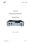
Front and
Back Panel
Layout
oo
C)o
FTPASS
Hl
I
ltlPUT
vo."*
ffi
FEEOBrcK
sr6LE
LEvEL
F
,
oUTPUT
voLUrE
I
I
axrst rxv
lE
I
I
UP
Elffi@ E@l= @ls
_
o.
Ofl
o€prx olgrl I
rl
,
o.g',
orol-
rcl_
J-
t-
,TE SWITCH
@
DGITAI, DETAY SDE-2OOO
\t
r..
l./
\_/
iffi
I Iffi^*
\\//
l.*,
=l
= i ,eForano C
FEEDSACKRLOOPN
@@:@@ @@
v
Table of
Contents
lntroduction
1
nt a nd Ba ck Pa ne I Layout
Explanation of Controls
F
ro
.
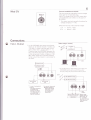
Co n nect io ns
Sample Sounds.
Sample Notes .
Block
1
2
6
B
I
D iagra m
11
Frequency Response
Specifications
12
13
2
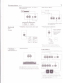
Control Descri tions
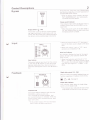
(keyboard amp, guitar arnp. etc.).Bypass opera-
Bypass
tion f unctions regardless of o nlofl operation of
BYPASS
the SDE-2000 Power suPPlY-
oN/oFF
)+
With the Bypass switch pressed, the OUTP
UT
M lX
E
D/D
E
LAY are
mechan ica I lY
connected with the INPUT.
Bypass switch indicator
Th is ind icator lights when the Bypass switch is
pressed, showing that the SDE-2000 is in Bypass mode.
)F
Bypassswitchtl:ON)
This switch is used to directly connect preced-
When the power supply of the SDE-2000 is
off , this indicator does not light, even when
the By pass w itch is Pressed
ng stage i nstru ments ( i nstru ments w ith I i ne
inputs, such as a gu itar input, passing through a
line d river) and succeed ing stage instru ments
.
i
*
INPUT
When th is control is set to "5" , rhe output
level of the d irect sou nd is equal to the input
leve
VOLUME
I
.
r( When
this control is set to "10", input
sensit iv
lnput volume
This control adjusts input level. Set this control
so that the +6 63 segment of the lnput level
indicator lights when input level is max imum.
Distortion starting level is set at + 12 dB above
ity is increased
bV 7 d B.
lnput level indicator
Th is indicator d isplays the level of the signal
passing through Level selection switch and
lnput volume.
)F
When Level selection switch is set ro "*4
dBm" (*20 dBm), and lnput volume is set at
"5" position, this indicator displays "0 dBm"
with the input signal of " +4 dBm " l-20
dB m).
O
VU.
Single delay switch (
Feedback
I
: ON)
When this switch is pressed, feedback does not
regardless of feedback level setting.
function
-
rf>
See Page 5.
Single delay indicator
Th is ind icator lights when
switch is in the single mode.
)e
Feedback level
Th is control adjusts feedback level when the
SDE-2000 is used as an echo unit.
Turn clockwise to increase feedback level
and cou nterclockw ise to decrease. With th is
contro I turned f u lly counterclockw ise, feedback level ls zero.
*- lf this control is set to "B" (3 o'clock posi-
tion) or over, oscillation may occur.
the single delay
This indicator also indicates the state of the
single delay remote iack on the rear panel.
i
Control Descriptions
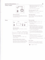
Delay Output
(cont
3
)
)E
When th is contro I is set at " 5'', the output
level is equal to the input level.
When this control is set at" 10", output level
is increased by 6 dB.
DELAY OUTPUT
PHASE
INV
VOLUME
;e D
irect
sou
nd rema ins u nchanged
Delay phase switch ( I
"
: INV)
Th is sw itch reverses the po larity of delay sou nd
when pressed.
t
r+
Direct sound remains unchanged.
Delay output volume
Delay phase indicator
Th is control adjusts the delay sou nd vo lu me.
Turn clockwise to increase volume, and counter-
Th
clockwise to decrease.
phase is i nverted
is ind icator lights when the Delay
switch is pressed.
lt
phase
lights while delay sound
.
Delay time display
Delay
This display indicates delay time(ms) in
use,
with three-digit number.
It The display will change according to the
fo llow ing states.
g
(a) MODULATION:
OFF
The d isp lay ind icates delay t ime set by the
Delay time selection button. The dot located
lower-right hand of Display window f lashes
when the selected delay time exceeds 1 00 ms.
The flash rate is proportional to the period
of delay time being displayed.
Delay range switch
snu itch when a long delay, exceed ing
Press th is
32A ms, is used.
(b) MODU LATION WITH
Delay . time
^f
OFF (x1)
loN
&21
0-320ms
0-640ms
1oH z
-
16kHz
t*t!
os
off
I
(c)
press-
dot
is
.
MO DU LAT ION W ITH
CON TR O L VO LTAG
sw
ILT-IN LFO
ing the sw itch rema ins f ixed and the
loHz -7.2kHz (*13dB)r
Delay range {x2l indicator
Th is ind icator lights when the
BU
A value displayed immediately before
Frequency response
E
XTE R NAL
E
The display accordingly indicates delay time
De
lay
which is varied by externalvoltage and the
dot f lashes with its cycle.
The dot flashes when the delay time exceeds
range
itch is pressed.
100 ms.
Delay time selection buttons (up-down)
This button is used to set deiay time. Hold
down the button you have chosen and press the
other button as well, the change w ill be exceedingly quick and setting will be done sl.riftly.
Delay ind icator
Th is ind icator is used
to ind icate the state of
the Delay remote control jack on the
rear
panel, and lights while delay sound is delivered.
l=l .-_ -1
(:J
L_J
See pase 5.
4
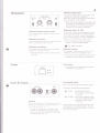
Modulation
Modulation depth control
RATE-----]
WAVEFORM
I /\/
.r- n,
:t
-t
D€PTH
rEr
@@ g
>-
O.lHz
>-.-/r10
O
lOtlz
This control adjusts depth of the built-in LFO
modu lation or external modu lation.
When this control is turned fully counterclockw ise , mod u lat ion is not af fected
.
'E When an externalvoltage is connected to the
CV I N jack on the rear panel, built-in LFO is
automat ica I ly cut; th is contro I a lso adjusts
the depth of the external modulation.
Modu lation waveform selection switch
This is the waveform selection switch for the
built-in LFO.
Modulation rate control
Th is control adjusts oscillation f requency of the
built-in LFO from 0.'1 Hz to 10 Hz.
Modulation switch
This indicator flashes showing the oscillat ion
frequency of the built-in LFO.
+F
When modu lation is off , th is ind icator does
not f lash
Power
+
T,
: ON)
This switch controls o nloff operation of the
built-in l-FO modu lation or external modulation. While this switch is used, modulation
effect can be turned off at a touch regardless of
position of the Modu lation depth control.
ie While the
Delay
time selection button
is
pressed, modu lation has no effect.
n A +
Modu lation rate indicator
(
see Pase 5'
Modulation indicator
This indicator lights when the built-in LFO
modu lation or external modu lation is on.
r+
This indicator also indicates the state of the
Modu lation remote jack on the rear panel.
Power switch
T
I
POWER
m med
iately after Power
on, delay time is set at 0
---
ON
r
OFF
lnput & Output
sw
ms.
itch
is tu rned
Level selection switch
Th is is the
Example
I
+4
inputloutput level selection switch.
of input/output
dBm
o
o
level selection
Roland Rack System
Professional Audio Equipment, etc.
t -20 dBm oElectronic Musical
lnput iack
This is the input jack for the standard plug. lnput
sensitivity is +4 dBm or -20 dBm when the
lnput volume is set at "5"
.
* ln case of
connecting " Low-level lnstruments" such as Electric guitar, Bass Guitar,
M ic etc., use the unit to match the level such
as Pre-amp, Mic-amp, etc.
lnstru-
ments, includ ing keyboards.
cStandard Audio Equipment, etc.
ln some cases, input level cannot be set to the
sett ing va lu es of t he above ex a m p le. I n su ch
the controls as follows to obtain
the proper input level.
cases, operate
Control Descrl tions
(1
)
(cont
)
Adjust the lnput volume so that the input
level indicator shou ld show +6 dB when
the maximum input is applied to the input
20A0 are equa:. CcnS€Q-er,l;v :ne cuiptjt
level remains unchanged even when the
position of the Level selection switch changes.
jack.
(2) Atthistime,
t
'
3'
if the lnputvolume isbetween
is proper.
' and " 10" the 'input level
(3) When the lnput volume is "'l " or 't2t', set
the Level selection switch to "+4 dBm"
(projected position) .
When only the -20 dB segment of the
lnput level indicator lights, even when the
lnput volume is " 1 0", set the Level selec-
tion sn'litch to "-20 dBm"
(pressed
position).
tt
The input level and output level of the SDE-
Mixed, Delay output
t+ ln case
of using MIXED OUTPUT.
The direct sound and delay sound are mixed
and outputted.
* ln case of using
only DELAY OUTPUT.
Only delay sound is taken out from SDE-
2000.
t+ I n case of using both outputs.
The direct sound is provided from MIXED
ouTP uT, the delay sou nd is provided f rom
D E LAY OU TPUT.
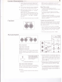
Feedback loop send/return iacks
Feedback
These are input/output jacks for the standard
plugs. When the SDE-2000 is used as an echo
unit these terminals are used to change feedback characteristics.
FEEDBACK LOOP
SEND
RETURN
@@
+4dBm
+F
The f irst delay sou nd remains
u
nchanged.
tt When connecting an instrument to the Feedback send lreturn jacks, use the one whose
ga in is ad justab le to u n ity ( input: output =
+4dBm
1 :1).
)+
The rating input/output level: +4 dBm
Remote Switch
FS-1- ,B-f
A-r
@o:@o
DP-2
O€LAY ON. OFF
@
Delay remote iack
E Turn on the
single delay
rg
sw itch.
Single delay remote iack
sw
tr
@
;Hi
DELAY
SOUND ON
JE!-
-t
MODULATION
E
I
E
ON/OFF
switch.
,
b
DELAY
ON OFF
tf
DELAY
SOUND OFF
S$FTE
1d.-
UODUI-ATloil
Turn on the
Modulation
ately
ON-OFF
:F{:
,H.
*
T
H
MODULATIOIiI
ox/ofF
qr.
I
I
Jlt-
itch.
't
DP-2's circuit
is as
shown in
the left f igure. Normally
circuit is closed (ON state).
While pedal is stepped on,
circuit
is opened.
-- lt opens when stepped on.
Hold remote control switch iack
When a remote control switch is connected to
this jack, repeat hold effect, which allows input
sound to be end lessly repeated, is obtained.
Operation:
1
(Onty remote
control.)
sll{cLE
Modulation remote iack
Connect ion of a remote contro I sw itch al lows
On/Off operation. Use Roland's FS-1 Foot
Switch or DP-2 Pedal Switch remote control
/
E
Altern-
. Connect the DP-2 remote control switch to
th is jack.
2. Operate the Delay time selection button on
the front panel to set the longest delay time.
(When the Delay range switch on the.front
panel is at X 1 position delay time is approx.
334 ffis, and at X2 position, delay time
approx. 668 ms. )
is
is stepped on while sound
being generated, the sound generated just
is reproduced after 334 ms or 668
is
3. When the DP-2
H"re
tt ln normal
setting sound is reproduced at
the repeating period of 334 ms or 668 ms.
The repeating period can be changed by
applying a DC vo ltage to the CV lN jack on
the rear panel.
6
Mod CV
External modulation CV lN jack
Th is is an external modulation control voltage
input jack for the standard plug.
lnput CV voltage from the LFO output jack
of synthesizers and others to this jack of
MOD CV
sD E-2000.
@
r( This input terminal normally functions for
voltages ranging 0 '\' +10V.
De
layt ime-vary ing u nder externa I vo ltage.
0v ->
10V +
Connections
lnput, Output
approx " +15%
approx, -35%
[When using E. Guitar]
)F
ln
th is SDE-2000 the rating input/output
levels can be shifted between +4 dBm and
-20 dBm, in either case the gain will be
unity (input level : output level - 1 : 1).
Therefore use this SDE-2000 between the
two units which send and receive the signal
in the rating level of either +4 dBm or -20
dBm. When those two units have different
Pre-amp
or
line-driver
rating output/input levels it is not proper to
use them.
Preceding unit
G
uitar amp
I'nput/Output level
Guitar amp
selection switch
+ 4dBm
-2O dBm
lf the
Pre-amp or line-driver is not used, the
SD E-2000 can be set up
with the gu itar
amp by using its pre-out and main-in jacks.
SIP-300 (Pre-amp)
SIP-301 (Pre-amp)
*
ln case of using both
outputs.
The direct sound is
provided from
M IXED OUTPUT
The delay sound is
provided from
DE LAY OUTPUT
* ln case of
using only
MIXED OUTPUT
The direct sound
and delay sound
are mixed and
*4dBm
outputted.
(
Roland Rack System
Professional Audio
equ ipment
-20dBm)
When using
effect loop of
SIP series, set
to -20 dBm
position of lnput
level selection
switch.
Connections
7
(cont.)
[Wlren using Keyboard Amp., PA system or
Aud io equ ipmentl
ruu|r\
'iur$ll
Fffi
[When using P.A" Mixer]
Echo send
MIX ER
Echo return
Set level selection switch to matching
position according to In/Out level of
the connected u nit.
P.A. u n its
Aud io
equ ipment
External
i3 Modulation using external
control
signal
rF
Remote control for delay time
CVT
I
'F Step on the Pedal to
shorten delaY time.
nput
''t
Be sure
to connect
DC 10V to lnPut
Jack of Foot
Volume.
Foot Volume
(FV -20 etc.
)
* When an external CV input jack is being connected to the externalvoltage O.V, delay time
will become longer by approximately 15 per cent.
Feedback
Send lReturn
* Graphic Equalizer
o sDE-2000x2
1
.2 second long delay can be obtained by using
sets of SDE-2000.
two
**?"t'l,rro
@@
@(d @@-rc
sDE -2000
sEo-331
When SDE-2000 is being set in Echo mode,
SDE-2000 can provide special effects of Echo
by controlling frequency response of feedback.
e6@
SDE -2000 No.2
De
lay
{
sou nd
Amp.
Direct sound
AmP.
)t Feedback level shou ld be adjusted on
SDE-
2000 No.1. SDE-2000 No.2 should be used
with the single delay switch on the
front panel held down.
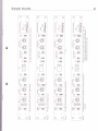
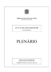
Sample Sounds
B
C
o
o
o
c{
OC
I
lrl
o
t
trJ
o
g
(,
C
oo
FO
K
z rC
o
EC
H ::G
;;o
sl-lp
"I-Jru
=
CC
d
E
o
o
3 .l-l
O
HFI
ltr
-LJIroJ
$
F
lL:
o
FE
FO
ilH 6iloE F
3 rl
.t-tE
E
ltr
"LJIroJ
H
E ;t-.l8
(l)
P
(o
(l)c
-co
l-},
.€
E
lt:
o
7:6
o-
sHm
P'\
)
(o=
$p".--me
o
lf, (l)
(o
(t)
T]
-o
c
(u
6
(l)
ll
O
(o
gti
-o
mm
!(l)
6*@"
'l
:
gti
(I)
Mm
o:E
L)n
{-,LF
-v
o.<o tr
g cE
r'', o
1)F-o ot
.t
a
C
<b
o
-@:
Ei
e
dr
"3Hflmil
r
>
(u
rr--ro
-@"
E;
-@"
E3
(l)
YfrY*
"3'[,--lffi
"9Hffiffi
H
ui
.9
o
C)
ur'@."
"$iHM
IJJ
UJ
q)
!A(
o)
-c
-c
.ts
=
o
O
(t)
(o
LL
o
I
o
H
(I)
"g;,q(--re
o)
(l)
C
, ytr=
uq-v"
G
.=
.9
e
J1'
w2
J1'
llJ Z rtr
T)
uq-v"
;Hm
l!
ir-+m
IH[[m
a
,n
ct)
:f-c x!{
:r-ffi
5t'Y"
E:
.-{-l
o
-rfrJ-
E
.PP
tJ) (D .-
(t)
F=
(l) O.=
F9;8.ec
-o
o
FEo
gli m
?
0.)
!-\(
((l
lF
-CP(D
P (o_C
rr- -C P
5n
ul
-ff
^.'
Y
Lb
-F
I-
oo'n
6*@"
5-n
o-c
E
*d
e
o
\v/^
>\r-'(
Zlcol.ol(nl.ol
lolElEIEl
l@l('lolol
l*l*l
i-l--il
ltl
m
:
(g
E
(t)
o
o.
(1)
(o
(J
o
E
ct)
.=
k
d=
"$Hilm
!
E
o
o
E
.9
(J
rr@"
-o
"ftHffi
(l)
UJ
lrl
Ec)
v)
t1
o-
x
]C
o)
q)
c(It
-o
(o
(I)
q)
#(tr
o)
q)
q)
tn
-o
#
P
U7
f,
!
o
o
o
(t)
a
N
J
O
-o
(g
-o
]J
q)
-c
(t)
c
(J
Co
LU
LL
o
o
(J
o
at)
U)
v7O
fC
OO
'6(t)
(oE
O-C
Acg
o
I
o
(J
tU
u-
E
I
o
C
CO
EO
EE
ilH 6rt(O
vr-
fi :t-18
"LJzu
E
o
o
Ell
1:6
fr s[18
"L-rfzu
$
lr-r
o
o
o
o
c{
r.L
o
o
uF
7FL.
;:o
.t-}6
Hl ltr
t
lrl
a
"LJru
p
o
o
gll
TL
ll
l!
En
3n
lt
gilm
mm
t
3n
o
z
o
t
Hll
UJ
o
"gtHM
l!z
dl
-@"
irl m
ir-ro
rE-A'
gd-v"
"3ro
E;
a
@"
dgr--um
U2
Ei@"
Et@"
gHmr
Eu@"
"$HM
ffgn--m
ffgn--m
ffgr--m
LIJ
trJ
ll- ..,
o
I
"HHffi
lu
o
@:
l_J
J;
T
$gn-m
;Hm
iro
;Hmm
e
1.5
3fi
E
e
'lail
I
o
E3
Itr
at{M
o
=
o
EEI
"'
$
6
E=@
uJ
o
;;LO
H
tl"€[
eJcL
iro
CC
!n
rl-ff
mm
o
EE
_E
5n
rl-@:
o
v
@"
-E
5n
o
()
SHM
tHmm
6E@"
o
o
C
*
:Hm
ill
o
C
C
o
c
C
ut
llJ
uJ
"iHffiffi
CC
CO
C
C
o
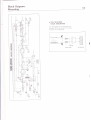
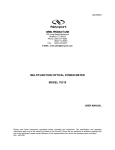
Block Diagram,
Mounting
11
F
d
F
I
2r-
3
t-+
6
R55
frae
Et
ur:
[Cr'
E-+
o THE SDE-2000
RACK MOUNTING
The SDE-2000 can be mounted in a
standard 19" rack using 5 m m screws
as shown in the drawing-
@+
{
=
E,
o
6
Y
o
o
J
19" RACK
6
o
o
o
sl
rir
o
a
t\
t-(
I:+
:
a
c-+
6
< Fa
3;I
d aoI
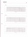
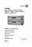
Frequency
Response
X
Delay
(
12
0-320ms
Delay
x2
(0-640ms
Direct
I
)
)
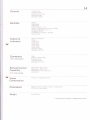
13
Specificaitons
* DIGITAL DELAY * SDE.2OOO
I
+4 dBm 1+Zg dBm max)
nput Level
-20
)
lnput lmpedance
56kQ
Output Level
+4 dBm (+18 dBm max)/600o load
load
-20 dBm (-A dBm max)/1OkSt
Ou
Feedback
dB m 1+S d Bm max
tput
I
mPedance
1 00S)
650S)
l+q dBm position
l-ZO dBm position, M ixed output
550O I -ZO d Bm position, Delay output
Level
Feedback Send
:
+4 dBm
(+1
Output lmPedance
Level
Feedback Return
6 dBm max)
:
100S)
: +4 dBm (+19 dBm max)
: TBkO
lnput lmpedance
: 0-+1 0V (t20V, allowable)
lnput lmpedance: 90kfl
CV ln
Modulation CV lnput
Operating Voltage
General
Performance
Delay Time
0 to 320 ms
0 to 640 ms (in 1 ms stePs)
Delay Accuracy
!0.5%
F req
uency Respo
nse
Signal to Noise Ratio
(lHF A) at rated inPut
1O
Hzto100
90 dB
B0 dB
Dynamic Range (lHF A)
G
Total Harmonic Distortion
at rated inPut & outPut
kHz +0,-1 dB lDirect
+0.5, -3 dB lDelay,0 to 320 ms
10 Hzro 16 kHz
10 HzroT.2kHz +0.5 ,-3 dB / Delay,0 to 640 ms
& output
Ref. 1 kHz
i
I Direct
/ Delay
I D irect
90 dB / DelaY
reater than 1 12 dB
Less than 0.05% I Direct
0.08% typ ,0.2% max / DelaY
r'
t
14
Controls
Switches
ln put Vo lu me
Feedback Level
Delay Output Volume
Modu lation Rate
Modu lation Depth
By pass
ing le De lay
Delay Phase
S
Delay Range (x 1,x21
Delay Time Selection Buttons ( Up, DOWN
Modulation Waveform ( A/,tu )
M odu lation On-Of f
Level Selection (+4 dBm, -20 dBm)
Power On-Off
)
Delay Time Display
Display &
lndicators
Bypass
lrrput
S ing
Level
le De lay
Delay Phase
Delay
Range
.
Delay On-Off
Modulation Rate
Modu lat ion On -Of
Connectors
(1
l4' ' phone jacks)
Remote Control
Capability
(1
14" phone jacks)
I
f
nput
Output - Mixed, Delay
Feed Back Send
Feed Back Retu rn
Mod u lat ion CV' I nput
Delay On-Off (DP-2, FS-1 )
Single Delay (DP-2, FS-1)
Modulation On-Off (DP-Z. FS-1 )
Hold (DP-2)
Power
Consumption
27W (1 17V), 3OW (22OV ,24OV)
Dimensions
482(W) x 47 (H) x 355(D) mm (19 x 17lB x 14 in.)
19'' (E lA- 1 U ) rack mou nt
Weight
5.5kg (12 lbs.)
* Specifications
\
are subject
to
change
without notice.
\U
Y
SDE-2000 OWNER'S
MANUAL '82 Aug. B-3
Roland Corporation