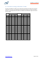
1
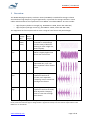
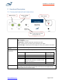
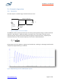
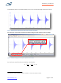
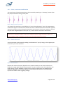
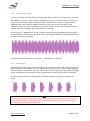
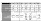
HFIT600A | User Manual WHALETEQ High Frequency Insulation Tetser Operation Manual Issued 1 August 2014 www.whaleteq.com Page 1 of 26 HFIT600A | User Manual CONTENTS 1 2 3 4 5 5.1 5.2 5.3 5.4 5.4.1 5.4.2 5.4.3 5.4.4 5.4.5 5.4.6 5.4.7 5.4.8 5.4.9 5.5 6 6.1 6.2 6.3 7 7.1 7.2 7.3 7.4 8 8.1 8.2 8.3 9 10 Overview History of development Significant Risks Getting started Functional Description Front panel controls and connections Rear panel connections Connection to external equipment and test load Principle of operation Basic pulse Pulse, crest factor modification Basic sine wave Modified sine mode Burst mode Effect of the test load (insulation under test) Effect of test sample breakdown Voltage divider Current divider Protection systems (beeping alarms) Operation HF Dielectric strength testing Test table according to IEC 60601-2-2:2009 HF Leakage current testing HF insulation breakdown – theory and detection Thermal effects / dielectric dissipation factor () Dielectric breakdown Corona Limitations in IEC 60601-2-2 Calibration Background Voltage divider (1000:1) Current monitor (1Ω shunt) Specifications Contact details www.whaleteq.com 3 5 6 7 8 8 9 10 11 11 13 13 14 14 15 15 16 16 17 18 18 19 20 21 21 22 22 23 24 24 24 25 25 26 Page 2 of 26 HFIT600A | User Manual 1 Overview The WHALETEQ High Frequency Insulation Tester (HFIT600A) is intended for testing insulation associated with high frequency surgical applications, in particular for testing insulation in active cables and electrodes to the requirements in IEC 60601-2-2 and IEC 60601-2-18. Tests include: o o High frequency dielectric strength (e.g. IEC 60601-2-2:2009, Clause 201.8.8.3.103) High frequency leakage current (e.g. IEC 60601-2-2:2001, Clause 201.8.8.3.102) The equipment has four output mode to cover a range of crest factors and peak voltages: Mode Sine Peak voltage (Vp) 1600 (1200 Vrms) Crest factor (range*) 1.4 Description Essentially sinusoidal, intended for cable leakage and also study of dielectric heating (as it has a high rms, with low peak). Amplitude modulated to obtain a slightly higher crest factor than a sine wave. Modified 2000 sine 1.8 Burst 3500 2.0-6.0 Bursts of sine waves, with adjustable duty cycle. The burst repetition rate is fixed at 12kHz Pulse Low 4750 4.0 - 6.0 Decaying sine waves, pulse repetition rate fixes at 11.7kHz, with adjustable “damping” time to create low and high crest factors. Pulse High 7200 4.0 - 6.0 Waveform Low crest factor High crest factor Low crest factor High crest factor Decaying sine waves, pulse repetition rate fixes at 12kHz, with adjustable “damping” time to create low and high crest factors. *Crest factor ranges are approximate only, and will depend on the load capacitance and dissipation factor. The Burst, Pulse Low and Pulse High are designed with a significant overlap to ensure that the requirements in IEC 60601-2-2 can be fulfilled. www.whaleteq.com Page 3 of 26 HFIT600A | User Manual For each of the modes, the fundamental frequency is around 330kHz (full load, 100pF) and 440kHz no load. In addition the equipment is provided with two BNC outputs for monitoring the test via oscilloscope: - voltage monitor (1V/1000V, 1000:1 HF divider) current monitor (1V/A, 1Ω shunt) To operate the equipment the user will an oscilloscope. The equipment cannot be used without this supplementary equipment. As of August 2014, equipment is provided with a dedicated 48Vdc power supply. In order to operate this equipment, the user should be a qualified electrical engineer or equivalent, familiar with principles of high frequency insulation and the use of oscilloscopes. The user should review the principle of operation of this equipment and the section on significant risks. The following history of development helps to understand the principle of operation and significant characteristics. www.whaleteq.com Page 4 of 26 HFIT600A | User Manual 2 History of development Until now, high frequency insulation testing has been mostly performed using electrosurgical equipment (ESUs) together with transformers to gain higher peak voltages. High voltage probes (100MΩ, 1000:1) and oscilloscopes are typically used to monitor the voltage during the test, current probes for monitoring leakage current. Unfortunately , ESUs are intended for providing brute power for cutting and coagulation; they rarely provide the fine adjustment necessary for testing and studying high frequency insulation: adjusting the peak voltage and crest factor to fit the requirements in the standard maybe difficult; the addition of transformers on the output to step up the voltage often creates unexpected problems; the feedback loop of many ESUs is not particularly stable, and the ESU may be damaged by the test, especially for high capacitive loads. HV probes used to monitor the output have also been found to be inaccurate at high frequency. At dc and low frequency, they are primarily resistive, accurate to around ±3%. At frequencies above 10kHz, the probes operate in a capacitive region, where any calibration is no longer valid. Even with probe “compensation”, errors of 10 to 20% are typical. HF current probes have similar problems. These issues provided the incentive to develop a high frequency insulation tester with a stable output, adjustable peak voltage and crest factor, with a built in voltage and current monitor custom designed to fit with test requirements of IEC 60601-2-2. Early in the design process, the impact of test sample’s capacitance became apparent. A 15cm length of cable tested at 6000Vp at mains frequency (50-60Hz) would typically have around 100-200µA flowing in the insulation due to capacitance. The same insulation tested at 400kHz can easily have peak currents in the order of 1-2A, with peak loads in the order of 10kVA. Although this is apparent (not real) power, it turns out that capacitive loads are the most inefficient for a standard push pull amplifier to drive. It is estimated that a HF amplifier in the order of 1-2kW would be needed for testing the full range of HF insulation. To overcome this problem, a resonant circuit which can create peak outputs of well over 10kVA with an input power less than 150W. As the load under test is part of the resonant circuit, the test frequency depends on the test sample. A test sample will typically have around 10-70pF capacitance. The WHALETEQ HFIT is designed to stay within the range of 300-500kHz with loads of up to 100pF (or higher for models with lower peak output). An embedded 1000:1 divider was design using high quality mica capacitors which are extremely stable with frequency, voltage and temperature. This divider is accurate to better than 2% in the 300-500 kHz range. Similarly, a 1Ω HF shunt ensures reasonably accurate monitoring of HF current. The latest version (HFIT600A) incorporates microprocessor control, overload, over temperature and over voltage detection. Features being considered in the future include direct display of peak voltage, rms voltage, crest factor and rms current, or through PC monitoring (USB). www.whaleteq.com Page 5 of 26 HFIT600A | User Manual 3 Significant Risks As a result of risk assessment, the following significant risks/hazards were identified: Potential risk Information / Risk control Burns If the output is touched by the user when activated a burn hazard exists, similar to that provided by electrosurgical equipment. It is considered a similar risk to use of a soldering iron (i.e. typically minor, non-permanent injury). The following risk controls have been implemented: - The output controls are located well away from the output terminals The output is disabled until the voltage dial is set to zero when the power is turned on or the mode is changed (avoids unexpected output) In addition, the user should take care with the set up to minimize the likelihood of contact. Ozone If corona occurs during testing, it produces ozone which can be hazardous. Corona depends on the thickness of insulation and voltage. Thin insulation can produce corona and ozone at voltages as low as 2000Vp. Literature indicates that for most people, ozone should be avoided but small amounts should have little effect. For these people, the smell of ozone can be used as a good indicator of the need to take action. In rare cases, even small amounts of ozone, below that which can be detected by smelling, can cause adverse reactions. If ozone can be smelled, or in case of doubt, operate the test in a well-ventilated area, and/or limit the number of tests with time to reduce the volume of ozone. False positive If the equipment provides a false positive (pass test result when the insulation test should have failed), a potentially dangerous medical device could be released to market. This was determined to be the most serious risk associated with this equipment. The main risk control is user awareness and the following user actions: o Investigate the material properties (dielectric strength, dissipation factor) to confirm the suitability of the material independent to the test (see Section 6) o Visually monitor the applied voltage throughout the test o Test at least 3 samples; consider testing the material also to destruction o Perform temperature study (determine dissipation factor) As an additional risk control an audible overload indicator is provided which detects when the equipment’s feedback loop is unable to maintain the set voltage (see Section 4.5) Note: Although high voltages are involved, there is no significant risk of electric shock. The output is a tuned resonant circuit at high frequency, it is inherently unable to provide high currents at frequencies which are known to cause electric shock (<1kHz). www.whaleteq.com Page 6 of 26 HFIT600A | User Manual 4 Getting started This operation manual contains a significant amount of information. It is understood that users may wish to experiment with the controls prior to reading all the detail. In general the equipment is fairly robust and not easily damaged. The following key points should be checked before starting: The following beeping alarms are provided: o Slow beeping sound (2Hz): this is a zero start protection feature. Return the voltage output control to zero. This is included to prevent unexpected output. o Fast being sound (4Hz): indicates a possible overload, partial or complete breakdown condition (output is driving at the maximum possible). o Three beeps (repeated): indicates an output in excess of 1250Vrms (see below). o Continuous beep: indicates over-temperature for the main heatsink Avoid long duration output in excess of 1000Vrms In general there is no need to exceed 1000Vrms except for insulation rated above 5000Vp. The equipment is designed to test insulation rated up to 6000Vp, which requires a test of 7200Vp /1200Vrms for 30s. As the equipment is designed to cover a wide range of peak voltages and crest factors, it is possible create voltages with high rms values by selecting a mode with a high peak output and then adjusting for a low crest factor. These conditions are beyond the limits of the equipment and not necessary for normal testing. The following protection features are included to avoid damage to the equipment: o o o Pulse modes default to a low crest factor when selected Over-voltage detection (operates at approximately 1250Vrms) Over-temperature detection Values of up to 1200Vrms may be used for up to 60s with 30s cooling time between use. In general users should be monitoring the rms voltage to avoid triggering the over-voltage and over-temperature protection. For correct measurement of rms voltage by oscilloscope, always monitor at least 10 cycles of pulse waveforms, and ensure the sampling rate is at least 20MHz (20 Ms/s). Measurements based on few pulses or at low sample rates can give misleading results. Make sure to read the significant risks section (page before this one). To avoid burns do not touch the output when energized. www.whaleteq.com Page 7 of 26 HFIT600A | User Manual 5 Functional Description 5.1 Front panel controls and connections Mode Control Output voltage control Main output HF HV Output Adjust crest factor (for burst, pulse mode only Mode control Sets the mode as follows: Off – no output Sine – Outputs sine wave Modified Sine – Outputs amplitude modulated sine wave Burst – outputs burst of sine wave, burst repetition rate 12kHz Pulse Low, High - outputs pulses of decaying sine wave, pulse repetition rate 12kHz Output voltage control Crest factor adjustment Adjusts the output voltage Provides additional crest factor (CF) adjustment as follows: Mode Effect of crest factor adjustment Sine Modified Sine Burst Pulse, Low None None Adjusts the duty cycle of the waveform Adjust the point where damping is enabled (absorbs the waveform’s energy to create a higher crest factor) As above Pulse, High Main output www.whaleteq.com Crest factor range (approx.) 1.4 1.8 2.0 ~ 6.0 4.0 ~ 6.0 4.0 ~ 6.0 Main high frequency voltage output (up to 7200Vp). The red terminal provides the high voltage, the black terminal is connected to the frame of the equipment and negative (0V) terminal of the dc supply. Page 8 of 26 HFIT600A | User Manual 5.2 Rear panel connections Current monitor output Voltage monitor output Power adapter input Grounding terminal Current monitor BNC type connection for output to an oscilloscope. Output provides 1V/A of load current (1Ω shunt). For example, an output here of 200mVrms is equivalent to 200mArms current through the test load. Voltage monitor output BNC type connection for output to an oscilloscope. Output provides 1V/1000V of load voltage (1000:1 divider). For example, an output of here of 5.2Vp is equivalent to 5200Vp voltage on the test load. Power adapter input The equipment has been designed for an input of up to 48Vdc, with a dedicated power supply Grounding terminal Connects to the frame, negative terminal of the DC power supply and the shield (0V) side of the BNC outputs for the current and voltage monitors. Used to minimize noise and stray paths for high frequency current. Should be connected to the earth in the environment, the same earth that is used for the oscilloscope. www.whaleteq.com Page 9 of 26 HFIT600A | User Manual 5.3 Connection to external equipment and test load The following is the typical connection of the equipment Oscilloscope CH1 CH2 Voltage monitor Output Red Current monitor Black WHALETEQ HFIT600A Insulation under test Insulated support (e.g. plastic cutting board) Ground Environment ground (earth) Notes on the set up: o The common laboratory practice of disconnecting the oscilloscope earth should be avoided o All connections to the HV output (red terminal) should be minimized as far as possible, to minimize stray capacitance. Use short cables, suspended in air from the red terminal to the test sample. The area tested should be minimized as far as possible. For example, in the case of a long active electrode, the active electrode itself should be connected to the BLACK terminal, with the smaller test electrode applied to the surface of the insulation connected to the RED terminal: Connect the red terminal to the smallest electrode in the test sample; this minimizes stray capacitance R Surface test electrode B Insulation Active electrode (test sample) Insulation o The insulated support is necessary for the current monitor to work correctly. Otherwise, the return current may pass through environment ground rather than the internal 1Ω shunt. www.whaleteq.com Page 10 of 26 HFIT600A | User Manual 5.4 Principle of operation 5.4.1 Basic pulse The main output is created using a switched resonant circuit: Step up transformer L DC Power supply C MOSFET switch Figure 1: Simplified circuit of the HFIT600A The MOSFET switch is pulsed (turned on) for less than 1µs during which energy is stored in both the capacitor C and inductor L. When the switch is turned off, the L and C form a resonant circuit, transforming the energy back and forth between magnetic and electrical forms, coupled by the transformer (N turns). The resonant frequency of the circuit is determined from: 𝑁 𝑓𝑅 = 2𝜋 √𝐿𝐶 Heat energy is lost in the inductor, capacitor and transformer, resulting in a decaying waveform with a frequency of approximately fR, as follows: Figure 2: 4kVpeak decaying sine wave, 380kHz (1kV/div, 5µs/div) www.whaleteq.com Page 11 of 26 HFIT600A | User Manual If new MOSFET pulses are provided regularly, the result is a pulsed decaying waveform as follows: Figure 3: Repeated pulses of decaying sine waves (pulse repetition rate 10kHz)1 The crest factor of the output is determined from dividing the peak voltage by the rms voltage: Figure 4: A 380kHz decaying sine wave, pulse repetition rate of 10kHz The crest factor (CF) for the above waveform is calculated as: 𝐶𝐹 = 1 𝑉𝑝𝑒𝑎𝑘 4006 = = 5.00 𝑉𝑟𝑚𝑠 802 Note that as of February 2014, the pulse repetition rate has been fixed at 12kHz. www.whaleteq.com Page 12 of 26 HFIT600A | User Manual 5.4.2 Pulse, crest factor modification The crest factor of the pulse waveform can be increased by switching in a “damping” resistor (after the peak) to absorb the energy of the pulse. Figure 5: High crest factor pulse mode The timing of this switching is controlled by the “Crest factor adjustment” switch. The approximate crest factor range is 4.0 to 6.0, but the actual crest factor is affected by the load. The load is typically capacitive insulation, and increasing the capacitance will reduce the crest factor. However, the load may also have a high dissipation factor (see 7.1), in which case the crest factor will increase. Note: in this this mode it is possible to create high rms voltages. The equipment will default to high crest factor to avoid this situation. Take care to monitor the rms voltage and ensure it does not exceed 1200Vrms (60s) or 1000Vrms (continuous) when adjusting the crest factor. 5.4.3 Basic sine wave A sine wave mode can be created by adding a small amount of “top up” energy in the negative part of the each cycle in the waveform: Figure 6: Sine wave mode Because the resonant frequency depends on the capacitive load, the sine wave mode relies on feedback to trigger right timing of the top up pulse. To get the mode started, the equipment uses regular pulses until this feedback is effective. The minimum voltage which the feedback works reliably is 100Vpeak, and the point depends on the load (note this function is currently being improved to enable a lower triggering voltage). www.whaleteq.com Page 13 of 26 HFIT600A | User Manual 5.4.4 Modified sine mode In normal sine mode, the crest factor is not adjustable and is around 1.4 as expected for a sine wave. In IEC 60601-2-2, there is a small range of voltages which require a low crest factor (<2), and where using a sine wave would result in outputs well above 1000Vrms. For example, a rating of exactly 1600V requires a test voltage of 1920Vp. If the sine wave is used, the rms would be around 1360Vrms, which is not only beyond the limit of the HFIT, but also likely to cause extreme dielectric heating. The value is far higher than expected in the real world. For this testing , a “Modified sine” mode is available , which periodically disables the top up pulses, so the waveform naturally decays during this time. The resulting waveform is a modulated sine wave (modulation frequency of 20kHz): Figure 7: Modified sine wave mode This waveform has a crest factor of around 1.7 – 1.9 depending on the load. 5.4.5 Burst mode The burst mode combines the pulse mode and sine wave mode to create a mid-range crest factor of approximately 2.2 to 4.5 (again, actual CF range depend on the load). The circuit is initially triggered with a fixed pulse, and then the sine wave is allowed to run for a fixed period, after which the trigger pulses are disabled and the damping resistor is switched in to absorb the energy of the waveform. The duty cycle (period of sine : damping) can be adjusted using the “Crest Factor Adjustment” switch. Figure 8: Burst mode Note: in this this mode it is possible to create very high rms voltages. The equipment will default to high crest factor to avoid this situation. Take care to monitor the rms voltage and ensure it does not exceed 1200Vrms (60s) or 1000Vrms (continuous) when adjusting the crest factor. Overvoltage protection is provided at around 1250Vrms. www.whaleteq.com Page 14 of 26 HFIT600A | User Manual 5.4.6 Effect of the test load (insulation under test) The insulation under test will typically have a capacitance (CL) in the order of 10-100pF. This combines with the internal capacitance CH to form a resonant circuit: Step up transformer L DC Power supply MOSFET switch CH CL HFIT 7.0 As such, the capacitance CL will affect the resonant frequency and the test frequency. The resonant frequency is proportional to: 𝑓𝑅 ∝ 1 √𝐶𝐻 +𝐶𝐿 The internal capacitance CH has been selected so that the under no load condition (CL = 0), the resonant frequency is around 450kHz, while at maximum load (CL = max), the resonant frequency is above 300kHz (within the limits of the standard, 400kHz ± 100kHz). If a significantly larger load than rated is applied the resonant frequency may fall below 300kHz, the minimum allowed in the standard. The maximum load will depend on the peak voltage required by the user. Lower peak voltages can handle higher capacitive loads. 5.4.7 Effect of test sample breakdown Although the equipment operates in a resonant mode using apparent (not real) power, the equipment can still provide a large amount of power in the form of heat, well in excess of what is needed to destroy the insulation in the case that the limits of the insulation are exceeded. If the sample does breakdown, the current limit on the dc power supply will trip. The different types breakdown (dielectric strength, thermal, corona) are discussed in more detail in section 6, including ways to detect if breakdown has occurred. www.whaleteq.com Page 15 of 26 HFIT600A | User Manual 5.4.8 Voltage divider The internal voltage divider is constructed using high quality mica capacitors adjusted in production to ±1% between 300-500kHz. The output is buffered by an op-amp with an output impedance of 50Ω. This output should not be affected by BNC cables of 1m. 5.4.9 Current divider The current divider is constructed by a simple 1Ω ± 1% thin film resistor in series with the output, connected directly to the BNC connected without any buffering (not required due to the low resistance). When monitoring current it should be noted that higher frequency components will be “amplified” since the test load is essentially a capacitor (impedance reduces with frequency). In particular, when the MOSFET switch is on (see 4.4.1), higher frequency components may exist which are amplified in the current monitor. The effect is not significant when making rms measurements. It is recommended that only rms measurements are made from the current monitor (see Section 6.3 for more detail). www.whaleteq.com Page 16 of 26 HFIT600A | User Manual 5.5 Protection systems (beeping alarms) The following three detection/protection systems are provided: Zero start detection (slow beep, 2Hz): When the Mode is changed, the output dial must be set to minimum, otherwise a slow beeping sound (0.5Hz frequency) will be heard and no output will occur. This feature is there to prevent unexpected output when first turning on or when changing modes. The beeping sound will also be heard in the “Off” position. To clear the sound, set the output to minimum. Overload detection (fast beep, 4Hz): This indicates the voltage feedback loop cannot maintain the set voltage, which may be due to thermal runaway or breakdown in the insulation under test. This is a non-latched condition, it will clear automatically once the overload condition is removed. Overvoltage detection (3 beeps, repeated): This indicates the output has exceeded approximately 1250Vrms. The output will be disabled, and only re-enabled when the output voltage control is returned to zero. This is intended to prevent damage to the equipment. Temperature detection (continuous beep): This indicates that the internal thermal sensor on the internal MOSFET heat sinks has detected high temperatures, which may be due to continuous use or output short circuit. The output is stopped and a continuous beep is heard. This is a latched condition, and the user needs to return the output control to minimum to clear the audible indication and reenable the output. Typically the MOSFETs will cool quickly allowing use to continue, however it is recommended to allow at least 30s if heavy loads are expected, otherwise the temperature alarm will again trigger. www.whaleteq.com Page 17 of 26 HFIT600A | User Manual 6 Operation 6.1 HF Dielectric strength testing Always use the standard (e.g. IEC 60601-2-2) as the primary reference. The dielectric strength test should be performed according to the following procedure: - - Pre-condition the sample as required in the standard (e.g. sterilized, soaked in saline solution for 24hrs) Set up the equipment as shown in Section 5.3 Select a suitable mode for the peak voltage (See Section 1 for overview, Section 5.4 for details) With no load connected, verify that the required peak voltage and crest factor can be obtained If performing the test of the handle and electrodes, it is recommended to use a metal tray as the return electrode, in which the saline soaked cloth is placed (with the test sample inside the saline soaked cloth). The high voltage should be applied to the active electrode. The area tested should be minimized to keep capacitance within limits. If necessary test in two or more sections. If performing the wire wrap test, wrap the 0.4mm wire around the insulation as described in the standard. It is preferred to apply the high voltage to the wire instead of the active electrode (to minimize capacitance), and the active electrodes is the return path. During the test, monitor the test frequency, peak voltage and the crest factor, and load current for signs of corona, non-linear current or breakdown. See 6 for more detail. If beeping occurs and the output remains on, this means that feedback loop can no longer maintain the voltage selected. If the dc supply current limit is triggered, the test sample is likely to have broken down. If continuous beeping occurs (output is off) the over-temperature protection has tripped. Allow the equipment to cool down. If possible, reduce the test load (capacitance), test time or dc supply voltage to reduce internal heating. www.whaleteq.com Page 18 of 26 HFIT600A | User Manual 6.2 Test table according to IEC 60601-2-2:2009 According to IEC 60601-2-2:2009, the test voltage peak should always be 120% of the rated peak voltage. The crest factor varies depending on the rated peak voltage, and is allowed a moderate tolerance. The following table shows values up to 6000V, and the allowable range of crest factors and rms voltages. Vp (rated) 500 1000 1500 1600 1800 2000 2200 2400 2600 2800 3000 3200 3400 3600 3800 4000 4200 4400 4600 4800 5000 5200 5400 5600 5800 6000 Crest Factor Min Nominal Max 1.41 2 1.41 2 1.41 2 1.41 2 2.1 2.3 2.57 2.4 2.7 2.93 2.7 3.0 3.30 3 3.3 3.67 3.3 3.7 4.03 3.6 4.0 4.40 3.9 4.3 4.77 4.2 4.7 5.13 4.5 5.0 5.50 4.8 5.3 5.87 5.1 5.7 6.23 5.4 6.0 6.60 5.4 6.0 6.60 5.4 6.0 6.60 5.4 6.0 6.60 5.4 6.0 6.60 5.4 6.0 6.60 5.4 6.0 6.60 5.4 6.0 6.60 5.4 6.0 6.60 5.4 6.0 6.60 5.4 6.0 6.60 www.whaleteq.com Vp (test) 600 1200 1800 1920 2160 2400 2640 2880 3120 3360 3600 3840 4080 4320 4560 4800 5040 5280 5520 5760 6000 6240 6480 6720 6960 7200 Min 300 600 900 960 842 818 800 785 774 764 755 748 742 736 732 727 764 800 836 873 909 945 982 1018 1055 1091 Vrms Nominal 926 900 880 864 851 840 831 823 816 810 805 800 840 880 920 960 1000 1040 1080 1120 1160 1200 Max 426 851 1277 1362 1029 1000 978 960 945 933 923 914 907 900 894 889 933 978 1022 1067 1111 1156 1200 1244 1289 1333 Page 19 of 26 HFIT600A | User Manual 6.3 HF Leakage current testing For leakage current testing, use the following the procedure: - Set up the equipment as shown in Section 4.3 Select the sine mode. Immerse a known length of the test sample (insulated portion) in an insulated beaker, filled with saline solution Insert a return electrode Select the sine mode Apply a test voltage of 400Vp (about 280Vrms) Measure the rms current by oscilloscope (1mV = 1mA) Measure the test frequency by oscilloscope (in kHz) Calculate the allowable limit using the formula in the standard Although not clearly defined in the standard, it is recommended to use rms value rather than peak for several reasons. Leakage current is a defined term in the general standard, and when used in the general standard rms values are used. If peak values are used, the result is highly dependent on the test waveform, which may include short term high frequency components which are then amplified (due to the capacitive load) easily resulting in a failed result. The test waveform is not clearly defined in the standard. The main risk from leakage current at high frequency is heating, which is a function of the rms current, not peak current. If peak values are used, it is recommended to set the voltage to 400Vp using the positive part of the voltage waveform, and measure the peak current in the negative cycle of the test waveform. For the WHALETEQ HFIT, the switching transients occur in the opposite cycles which may affect the outcome of the test. Smooth part of the cycle, use for peak measurements Switching transients, ignore for peak measurements www.whaleteq.com Page 20 of 26 HFIT600A | User Manual 7 HF insulation breakdown – theory and detection 7.1 Thermal effects / dielectric dissipation factor () All insulating materials heat up when an ac voltage is applied. At very low frequencies, such as 50/60Hz mains, this effect is tiny and requires very high voltages to become significant. However at electrosurgery frequencies around 400kHz, the effect is significant at even at relatively low voltages, with some materials having observed temperatures exceeding 100°C well below 1000Vrms. The insulation under test can be modelled as an ideal capacitor in series with a resistor. The property of the material generally used is the “dissipation factor” or “loss tangent”, which needs to be measured around the frequency of interest. A dissipation factor of 1% effectively means that 1% of the impedance appears as resistive component, and 1% of the apparent power will end up as heat. For example, if the capacitance of a test sample is 100pF, has a dissipation factor = 2%, and is tested at 1000Vrms, 400kHz, the calculations are: C impedance = 1/(2π x 400k x 100p) = ~ 4000Ω Power (apparent) = 10002 x 2π x 400k x 100p = ~ 250VA Resistive component = 4000Ω x 2% = 80Ω Heat in test sample = 250VA x 2% = 5W Generally, the physical volume of the insulation in the test sample is small, so power of 5W can easily produce very high temperatures. However, the actual temperature will vary greatly depending on the set up and the test sample’s physical construction. If the insulation is tested in water, water will cool the insulation. If the test sample has a large metal surface it can also cool the insulation. Thick material can sometimes end up worse than thin materials, as the heat cannot escape from inside the insulation as easy. Different materials have different amounts of heating, for example Teflon has very low dissipation ( typically <0.1%), while PVC has relatively high dissipation (1-3%). The amount of heat produced is a function of the rms voltage squared, so a 10% increase in voltage can produce 21% more heat. The amount of heat is also a function of thickness squared (inverse), so a 10% reduction in thickness produces 21% more heat. As such, accurate control of the rms voltage is important for the test. Also, if the insulation thickness varies in real production, testing of multiple samples is reasonable. The HFIT has been tested with simulated high dissipation factor loads (100pF in series with 320Ω, = ~8%, around 10W resistive load at 1000Vrms, 300kHz). The output remained stable and was able to reach all specifications. A factor of = ~8% is expected to be well above all reasonable quality insulation at HF. In many cases, high temperatures in the order of 100°C can be reached but the insulation does not break down if this is below the thermal limits of the material. This is allowed in IEC 60601-2-2 (and www.whaleteq.com Page 21 of 26 HFIT600A | User Manual IEC 60601-2-18), but it may be undesirable particularly for insulation used in endoscopes or catheters (internal use). If the thermal limits of the material are reached, the insulation usually falls into thermal runaway and complete breakdown. This may eventually exceed the limits of the HFIT and cause the overload indicator (beeping sound with output on). It is recommended to research the dissipation factor for the material selected and confirm it is appropriate for use at the voltage specified. Also, it is possible to perform experiments on the temperature of the insulation. A method used by WHALETEQ is to wrap the insulation in thin copper foil (0.05mm) with a thermocouple inserted. Apply the HIT HF HV terminal to the internal conductor, and the HFIT Return terminal to the copper foil (to avoid damage of the temperature monitor/logger). Apply 30s of the rated voltage, and measure the temperature of the insulation at the end of test after the voltage is removed (during the test, the temperature monitor/logger may not accurately measure the temperature due to noise). It is recommended to avoid materials that have a temperature rise of more than 10°C at rated voltage2. 7.2 Dielectric breakdown All insulating materials have a breakdown point which the applied voltage will cause permanent breakdown. At high frequency, for most materials this voltage will higher than the other causes of breakdown documented here (thermal, corona). The material’s dielectric strength is normally easy to find in the material specifications, usually in kV/mm. It should be noted that the high frequency test is to be followed by a mains frequency test at 1kV above the rated voltage, which may be significantly higher than the peak high frequency test voltage. 7.3 Corona According to IEC 60601-2-2, blue corona can be ignored. However, test experience indicates this may be the main cause of breakdown, particularity for thin insulation. Corona is the breakdown of air around the edges of the test electrode. Corona releases heat and ozone, both of which can damage the surface of the insulation. If the insulation is thin, this surface damage may be enough to cause permanent breakdown. The presence of corona can be detected by a buzzing noise, the smell of ozone and the blue/purple light (which can be better seen in a darkened room). Small amounts of corona can be detected by oscilloscope (ns pulses in current monitor), and have been detected at voltages as low as 1200V, however intensity sufficient to damage insulation usually occurs at 1500V or higher. Test of multiple samples indicates that the onset of corona is fairly consistent, however, the onset of permanent breakdown is random, sometimes within 100V of visible corona, sometimes an additional 1000V causes no breakdown. Theoretical simulations indicate that the thinner the insulation, the lower the voltage at which corona occurs. Since the damage mechanism is surface 2 In real clinical situations, there are likely to be heat sinks around the insulation to reduce the temperature, and the voltage is unlikely to be applied for 30s. More research is required to develop an appropriate limit. www.whaleteq.com Page 22 of 26 HFIT600A | User Manual damage, thinner insulation is also more likely to be permanently damaged from corona. Therefore, thin insulation is particularly vulnerable to the effects of corona. It is recommended that if the insulation is thin (e.g. 200µm or less), there should be no visible corona at rated voltage. 7.4 Limitations in IEC 60601-2-2 Currently the standard has the following limitations: o There is no limit for the temperature of the material during tests. If the material is in direct contact with the patient, or in contact with devices that can transfer heat to the patient (e.g. cannula, endoscope, catheter), internal or external burns may occur if the material is a type that heats up significantly. o The applied rms voltage is not well controlled, being a function of the crest factor (see Table in 5.2). As the heating effect is a function of voltage squared the thermal effect can vary widely. The standard should have a thermal test at a fixed rms voltage. o The standard ignores the effects of corona, which may be significant for thin insulation. In other dielectric strength tests, corona can only be ignored if it stops when the voltage is reduced to rated voltage; such a requirement should also be considered for IEC 60601-2-2 o The standard only requires one sample to be tested. Small variations in insulation thickness can have large effects for thermal and corona, suggesting that tests on a number of samples is reasonable. For these reasons, it is strongly recommended that manufacturers research the material and ensure that the dissipation factor is appropriate, and thickness is controlled, and corona is minimized. www.whaleteq.com Page 23 of 26 HFIT600A | User Manual 8 Calibration 8.1 Background Calibration at high frequency is difficult, and complicated by the high value of the voltage divider ratio (1000:1). Users should be aware that it is unlikely for calibration laboratories to offer traceable calibration at 300-500kHz for a 7.5kV 1000:1 divider. In WHALETEQ laboratory, several methods have been developed to provide traceability which includes step up transformers to provide a high voltage level; the use of thermal methods to confirm flat frequency response in source equipment and for transfer and various cross checks. Such methods are unlikely to be repeated in general test laboratories. Most test laboratories will have a high voltage probe which is labelled as calibrated. Although such calibration in not actually valid at high frequency, for procedural reasons it may be preferred to record that HV probe as the “calibrated“ equipment while using the HFIT in built divider for reference. However it should be noted that HV probes with 10-20% error at high frequency are not uncommon . 8.2 Voltage divider (1000:1) This option uses a calibrated oscilloscope with two 1:1 inputs, and a function generator (FG). Due to the low voltages involved, this method may slightly overestimate the divider output. 1. Ensure the HFIT is powered on, with the mode set to OFF 2. Connect the FG output to the “HV HF” and “Return” terminals. 3. Connect CH1 of the oscilloscope to the same point (either the FG output or HFIT output terminals). Use only 1:1 probes or direct BNC cables. 4. Connect CH2 of the oscilloscope to the HFIT divider output (using a BNC to BNC cable). 5. Set the function generator (FG) to maximum (7Vrms, 20Vpp) sine wave, 400kHz 6. Verify the rms voltages at Ch1 and Ch2 are within 2% (CH1 should be ~7Vrms, CH2 should be ~7mVrms) Method 2: Using voltages generated in the equipment This option uses a calibrated oscilloscope with two 1:1 inputs, one of which can handle relatively high voltages (e.g. 100 or 200V). 1. Connect CH1 of the oscilloscope to the same point (either the FG output or HFIT output terminals). Use only 1:1 probes or direct BNC cables. 2. Connect CH2 of the oscilloscope to the HFIT divider output (using a BNC to BNC cable). 3. Set the output to pulse mode, slowly increase the output dial taking care not to exceed the limits of the CH1 input. 4. Compare the voltages measured at CH1 and CH2 are within 2% (peak and rms values) Note: these methods assume the oscilloscope 1:1 input is accurate at high frequency which is generally valid for high quality oscilloscopes. Some lower quality scopes are noted to have errors around 3%. If in doubt confirm Ch1 and Ch2 read the same prior to test. The rms method reduces the effect of noise. With the FG output off, noise should be less than <0.7mV (for <1% effect). Never use a divider (probes marked as 10:1, 100:1 or 1000:1) unless you are confident of the accuracy at the frequency range. www.whaleteq.com Page 24 of 26 HFIT600A | User Manual 8.3 Current monitor (1Ω shunt) The resistance of the current monitor can be confirmed as follows: 1. Pass a known current I between the Black “Return” terminal at the front and the green “Ground” terminal at the rear of the equipment. 2. Measure the voltage V at the BNC connector 3. Calculate the resistance (R = V/I) 4. Confirm the value is 1Ω ± 5% Note: for simplicity this test is done at dc, since high frequency resistors are used and the circuit construction is such that there is no significant stray capacitance/inductance relative to 1Ω. 9 Specifications The following key specifications are provided. Parameter Specification Sine mode At least 1000Vrms Sine mode, modified At least 2000Vp, crest factor 1.8+/0.2 Burst mode At least 3600Vp, crest factor 2.0 ~ 6.0 Pulse mode, Low At least 4750Vp, crest factor 4.0 ~ 6.0 Pulse mode, High At least 7200Vp, crest factor 4.0 ~ 6.0 No load frequency 420 ~ 450kHz Full load frequency (100pF) 300 ~ 340kHz Load dissipation factor 5% Voltage divider 1000:1±2% Buffered output to BNC socket (50Ω) Current monitor (shunt) 1Ω ± 5% (HF resistor), Non-buffered output to BNC socket Input voltage 48Vdc / 3.0A max Zero output detection When mode is changed, the output control must be set to minimum, otherwise no output occurs (2Hz beeping sound) Overload detection Operates when feedback cannot maintain voltage (4Hz beeping sound). Output remains on. Overvoltage protection Operates if the output exceeds 1250Vrms. Triple beep sound. Thermal protection Sensor on MOSFET heatsinks, operates at 70°C. Continuous beeping sound. www.whaleteq.com Notes Design tests to 8% Adjusted to ±1% from 300430kHz during production. Dedicated power supply To prevent unexpected output Uses rms/dc detection Page 25 of 26 HFIT600A | User Manual 10 Contact details WHALETEQ can be contacted by the following means: Email: Post: Phone: [email protected] 8F-3, No.106, Minquan W. Rd., Taipei City 10361, Taiwan +886 2 2550 1239 www.whaleteq.com Page 26 of 26