1
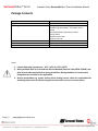
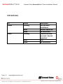
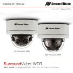
Surrou undVideo® Omn ni INST TALL LATIO ON MA ANUAL L AV12176DN-NL AV12176DN-28 AV12176DN-08 AV20175DN-NL AV20175DN-28 AV20175DN-08 SurroundVideo® Omni Arecont Vision SurroundVideo® Omni Installation Manual MicroDome™ Surface Mount Installation Contents Package Contents ....................................................................................................................................................... 3 Warranty Information ................................................................................................................................................ 4 Installation Overview ................................................................................................................................................. 5 Camera Setup ............................................................................................................................................................. 6 Camera Adjustment ................................................................................................................................................... 7 Camera Alignment ..................................................................................................................................................... 9 Installation ............................................................................................................................................................... 10 Changing the Lens .................................................................................................................................................... 11 Accessing the Digital Input and Output Connector ................................................................................................. 12 Digital Input and Output .......................................................................................................................................... 13 Auxiliary Power ........................................................................................................................................................ 14 LED Indicators .......................................................................................................................................................... 15 Support .................................................................................................................................................................... 16 Camera Discovery, Setup, and Configuration .......................................................................................................... 17 Wall Mount Accessory (AV‐WMJB) .......................................................................................................................... 18 Pendant Mount Accessory (AV‐PMJB) ..................................................................................................................... 19 Mount Template ...................................................................................................................................................... 20 Page | 2 [email protected] SurroundVideo® Omni Arecont Vision SurroundVideo® Omni Installation Manual Package Contents Item MegaPixel Camera Mounting Kit Power Cable I/O Cable Arecont Vision CD Description SurroundVideo® Omni Ceiling template 3x Mounting Screws (#6x1” for wood or sheet metal) 3x Drywall/Masonry Mounting Anchors Ceiling Gasket Network Patch Cable Security Torx Tool Aux Power Cord Digital Input and Output Adapter Manual, Warranty, Installation Software Notes: 1. Camera Operating Temperature : ‐40°C (‐40°F) to +50°C (122°F) 2. Wiring methods shall be in accordance with the National Electrical Code/NFPA 70/ANSI, and with all local codes and authorities having jurisdiction. Wiring should be UL Listed and/or Recognized wire suitable for the application. 3. Always use hardware e.g. screws, anchors, bolts, locking nuts etc. which are compatible with mounting surface and of sufficient length and construction to insure a secure mount. Page | 3 [email protected] SurroundVideo® Omni Arecont Vision SurroundVideo® Omni Installation Manual Warranty Information 3 Year Limited Warranty ARECONT VISION warrants to Purchaser (and only Purchaser) (the “Limited Warranty”), that: (a) each Product shall be free from material defects in material and workmanship for a period of thirty-six (36) months from the date of shipment (the “Warranty Period”); (b) during the Warranty Period, the Products will materially conform with the specification in the applicable documentation; (c) all licensed programs accompanying the Product (the “Licensed Programs”) will materially conform with applicable specifications. Notwithstanding the preceding provisions, ARECONT VISION shall have no obligation or responsibility with respect to any Product that (i) has been modified or altered without ARECONT VISION’s written authorization; (ii) has not been used in accordance with applicable documentation; (iii) has been subjected to unusual stress, neglect, misuse, abuse, improper storage, testing or connection; or unauthorized repair; or (iv) is no longer covered under the Warranty Period. ARECONT VISION MAKE NO WARRANTIES OR CONDITIONS, EXPRESS, IMPLIED, STATUTORY OR OTHERWISE, OTHER THAN THE EXPRESS LIMITED WARRANTIES MADE BY ARECONT VISION ABOVE, AND ARECONT VISION HEREBY SPECIFICALLY DISCLAIMS ALL OTHER EXPRESS, STATUTORY AND IMPLIED WARRANTIES AND CONDITIONS, INCLUDING THE IMPLIED WARRANTIES OF MERCHANTABILITY, FITNESS FOR A PARTICULAR PURPOSE, NON-INFRINGEMENT AND THE IMPLIED CONDITION OF SATISFACTORY QUALITY. ALL LICENSED PROGRAMS ARE LICENSED ON AN “AS IS” BASIS WITHOUT WARRANTY. ARECONT VISION DOES NOT WARRANT THAT (I) THE OPERATION OF THE PRODUCTS OR PARTS WILL BE UNINTERRUPTED OR ERROR FREE; (II) THE PRODUCTS OR PARTS AND DOCUMENTATION WILL MEET THE END USERS’ REQUIREMENTS; (III) THE PRODUCTS OR PARTS WILL OPERATE IN COMBINATIONS AND CONFIGURATIONS SELECTED BY THE END USER; OTHER THAN COMBINATIONS AND CONFIGURATIONS WITH PARTS OR OTHER PRODUCTS AUTHORIZED BY ARECONT VISION OR (IV) THAT ALL LICENSED PROGRAM ERRORS WILL BE CORRECTED. For RMA and Advance Replacement information visit ArecontVision.com Page | 4 [email protected] SurroundVideo® Omni Arecont Vision SurroundVideo® Omni Installation Manual Installation Overview Ceiling Gasket NPT Port Camera Housing Camera Gimbals (4X) Mounting Screws Gasket Captive Fasteners Page | 5 [email protected] Dome Cover SurroundVideo® Omni Arecont Vision SurroundVideo® Omni Installation Manual Camera Setup The SurroundVideo® Omni is user configurable. Each individual sensor can be positioned in a variety of ways. Below are some example configurations (top left to bottom right) 1. 270° 2. Straight Line 3. 360° or Hallway 4. 180° or Panoramic 5. Random Example 6. Random Example. Tech Tip Prior to installing the camera, thought should be given to the sensor positions. It is always easier to make adjustments before the camera is installed. Page | 6 [email protected] Surro oundVid deo® Om mni Arecont V Vision SurrroundVideo o® Omni In nstallation Manual Camera Adjusstment To positio on a sensor simply loosen tthe captive faastener to rel ease the cam mera assemblyy from the traack plate. Captive FFastener Track Platte Next, position the cam mera in the de esired location n on the trackk plate. Screw w holes aroun nd the circum mference are spaced in 5 degree increments. Note the arrowss marked at 445 degrees ass reference po oints. 100° 55° 00° Page | 7 [email protected] 45° Refference Maark Surro oundVid deo® Om mni Arecont V Vision SurrroundVideo o® Omni In nstallation Manual Sensor nu umbering is in ndicated on th he track plate e. The numbeer on the tracck plate correesponds to the sensor number in n the camera software. Tech Tip Sensor po ositioning and d alignment sh hould be considered beforre camera insstallation. It iis easier to ad djust the individuall camera positions before the camera iss installed intto a ceiling. TThe three slotts in the trackk plate provide additional adju ustment of th he camera aftter installatio n. Simply loo osen the threee screws to ro otate the n tighten the three screwss after alignment. This fea ture is most u useful for rep positioning th he cameras plate then mounted to the centerr locations aftter camera in nstallation. Page | 8 [email protected] Surro oundVid deo® Om mni Arecont V Vision SurrroundVideo o® Omni In nstallation Manual Camera Alignment Tech Tip Alignment of the individual cameras is critical to setup. The i ndividual cam meras when p placed on thee circumferrence of the track must be in a countercclockwise seqquence to creeate proper alignment wheen viewing the camera. Senso or 2 Sensor 3 3 Seensor 1 Sensor 4 Co ounterclockwise Senssor 3 Sensor 4 Seensor 2 Coun nterclockw wise Senssor 1 Page | 9 [email protected] SurroundVideo® Omni Arecont Vision SurroundVideo® Omni Installation Manual Installation 1. Wiring methods shall be in accordance with the National Electrical Code/NFPA 70/ANSI, and with all local codes and authorities having jurisdiction. Wiring should be UL Listed and/or Recognized wire suitable for the application. 2. Operating Temperature ‐40°C (‐40°F) to +50°C (122°F) 3. Always use hardware e.g. screws, anchors, bolts, locking nuts etc. which are compatible with mounting surface and of sufficient length and construction to insure a secure mount 4. Visit http://www.arecontvision.com/ and check to ensure your camera has the most current firmware. 5. If using the NPT port always use Teflon tape around threads to ensure proper sealing. 6. After plugging in the network cable check that the indicator LED’s are indicating the desired conditions (see LED Indicator table). 7. Use Arecont Vision software AV200 located on the CD or available for download at our website (www.arecontvision.com) for camera discovery and setup (see Instruction Manual located on CD or available on our website). 8. Adjust the individual cameras to obtain the desired fields of view (see Focusing Instructions). 9. Lens may be further secured by tightening the lens lock screw using Phillips head screwdriver. 10. Install the Dome Cover by aligning the captive fasteners with the mating threaded holes on the camera housing. 11. When mounting the Dome Cover to the Camera Housing ensure that the gasket is properly seating and not folded. Failure to do so may result in water and dust ingress. Best Practice Tips When mounting to vertical surface it is best to use the Wall Mount Accessory which includes a Junction Box. For outdoor use it is always best to properly seal the product using caulk around the edges to prevent water ingress from mounting to porous or uneven surfaces. Use Teflon tape on threaded interfaces. Page | 10 [email protected] SurroundVideo® Omni Arecont Vision SurroundVideo® Omni Installation Manual Focusing the Cameras 1. Open a live view of the camera from your web browser or the AV Software provided (AV200). 2. Loosen the lens lock screw using a phillips head screwdriver (if necessary). Only do so if lens seems very tight when turning. Lock screw should be tightened enough to provide some friction against the lens to avoid focusing problems. 3. Manually rotate the lens to adjust the focus until the desired image is obtained. 4. For some lenses a focus shift will occur once the bubble is in place. Hold the bubble up to the lens when focusing to account for the focus shift or see the “Focusing Alternate Lenses” section below for further instruction. 5. Retighten the lock screw if necessary. 6. Install the Dome Cover by aligning the captive fasteners with the mating threaded holes on the camera housing. 7. When mounting the Dome Cover to the Camera Housing ensure that the gasket is properly seating and not folded. Failure to do so may result in water and dust ingress. Tech Tip Changing the Lens 1. Remove the Dome Cover by loosening the captive fasteners. 2. Loosen the lens lock screw using a phillips head screwdriver (if necessary). Only do so if lens seems very tight when turning. 3. Manually unscrew the lens, this may take several seconds. 4. Replace lens. 5. Retighten the lock screw if necessary. 6. Reinstall Dome Cover per instructions outlined above. Page | 11 [email protected] Surro oundVid deo® Om mni Arecont V Vision SurrroundVideo o® Omni In nstallation Manual Focusing Alternate Le enses When foccusing the 6m mm, 8mm, 12m mm or 16mm m lens optionss you will enco ounter a focu us shift when using the bubble. TTo account for this follow tthese steps: 1. 2. 3. 4. Tech Tip Fo ocus the camera without tthe bubble. Rotate the lens per the chart below. The e rotation wi ll account forr most of the focus shift. h bubble on. YYou should be close to beiing focused. Put cover with Remove cover and rotate a couple degre ees at a time in either direection until yo ou gain the deesired image.. Lens MPM16.0 MPM12.0 MP PM8.0 MP PM6.0 16mm 12mm 8mm 6mm Rotattion <3/4 CCW W 1/4 CCW >1/8 CCW W 1/8 CCW 250° 90° 60° 45° Example: Using a 16mm m lens you will focus the le ens without tthe bubble un ntil you get th he desired im mage. Rotate the lens aalmost ¾ of a turn (250°). Put the bubb ble on and vieew the image.. It should bee almost in focus. Remove e the bubble and rotate a degree or ttwo in one dirrection and v iew the imagge with the bu ubble on. Depending on e you may nee ed to adjust in the oppositte direction oor continue in n the same dirrection until tthe desired the image image is o obtained. Accessing the e Digital Input an nd Output Conn nector The 4 possition connecctor inside cam mera housingg located on tthe main circu uit board used for I/O can be accessed by removing the track plate. Simplyy loosen the tthree screws indicated in tthe image below, lift the track plate and find tthe connectorr. The approxximate conne ector positionn is indicated by the red cirrcle below. Page | 12 suppo ort@arecontv vision.com SurroundVideo® Omni Arecont Vision SurroundVideo® Omni Installation Manual Digital Input and Output Use 4 position connector inside camera housing to interface with Digital I/O. DIGITAL I/O BLACK IN ‐ WHITE IN + YELLOW OUT ‐ ORANGE OUT + Electrical Characteristics Input Voltage (V) (Measured between + and – terminals) Output Current (mA) (Measured between + and – terminals) Applied Voltage Range : 0‐80V MIN MAX ON 2.9 6.3 OFF 0 1.3 ON ‐ 50 OFF ‐ 0.1 NOTE: Both the input and the output are electrically isolated from the rest of the camera’s electrical circuitry via general‐purpose photo couplers. The input is additionally protected with a serial 250 Ohm resistor and a debouncing circuit. Duration of any input signal should be at least 5ms to comply with the requirements of the debouncing circuit. Page | 13 [email protected] SurroundVideo® Omni Arecont Vision SurroundVideo® Omni Installation Manual Auxiliary Power If the camera is powered by a separate outside AC or DC power source, run the supplied power cable through the access hole on the camera housing and connect the power cable to the 2‐position connector on the main camera board. The approximate location of the 2‐position connector is circled in red below. NOTE: Wiring methods shall be in accordance with the National Electrical Code/NFPA 70/ANSI, and with all local codes and authorities having jurisdiction. Wiring should be UL Listed and/or Recognized wire suitable for the application Page | 14 [email protected] SurroundVideo® Omni Arecont Vision SurroundVideo® Omni Installation Manual LED Indicators LED Yellow Status Flashing Green Solid None Flashing Solid None Page | 15 [email protected] Description Link has been established. Normal Operation. No connection. Camera has been accessed. Normal operation. N/A No Connection. SurroundVideo® Omni Arecont Vision SurroundVideo® Omni Installation Manual Support 1. Arecont Vision FAQ Page Located at ArecontVision.com 2. Check the following before you call: Restore camera to factory default with AV100, AV200 or the camera webpage. Upgrade to the latest firmware by visiting ArecontVision.com. Isolate the camera on a dedicated network and test with AV100 or AV200. Swap the “troubled” camera with a known good camera to see if the problem follows the camera or stays at the location. 3. Contact Arecont Vision Technical Support one of three ways: 1. Online Portal : Support.ArecontVision.com 2. Phone : 1.818.937.0700 (option #1) 3. Email : [email protected] Page | 16 [email protected] SurroundVideo® Omni Arecont Vision SurroundVideo® Omni Installation Manual Camera Discovery, Setup, and Configuration For camera discovery and setup please use Arecont Vision software AV200 which you can find on the CD included with your camera or at: http://www.arecontvision.com/softwares.php The user manual for the AV200 software is included on the CD and is also located on our website. To configure the camera use either the AV200 software or the web interface utility. The web interface can be accessed by typing the camera IP address into your web browser or by clicking on the web interface button in AV200. The user manual for our web interface is included on the CD and is also located on our website. Page | 17 [email protected] Surro oundVid deo® Om mni Arecont V Vision SurrroundVideo o® Omni In nstallation Manual Wall M Mount A Accessorry (AV‐W WMJB) Gasket G Gasket Installattion Notes: 1. 4x mountin 4 ng screws aare #10x1” wood or ssheet metaal screws (4x mount anchors also include ed). 2. Always ens ure gasketts are prop A perly seatedd. 3. Use Teflon U tape on th hreaded intterfaces. Page | 18 suppo ort@arecontv vision.com Surro oundVid deo® Om mni Arecont V Vision SurrroundVideo o® Omni In nstallation Manual Pendaant Mou unt Accessory (A AV‐PMJB B) Gaskket Installation Notes: Gaasket ounting scrrews are #10x1” 1. 4x mo wood d or sheet m metal screw ws (4x moun nt anchors also includ ded). 2. Alwayys ensure ggaskets aree properly seated. 3. Use TTeflon tapee on thread ded interffaces. Page | 19 suppo ort@arecontv vision.com SurroundVideo® Omni Arecont Vision SurroundVideo® Omni Installation Manual Mount Template Page | 20 [email protected] SurroundVideo® Omni Arecont Vision SurroundVideo® Omni Installation Manual Contact Arecont Vision Technical Support one of three ways: Online Portal : Support.ArecontVision.com Phone : 1.818.937.0700 (option #1) Email : [email protected] Page | 21 [email protected]