1
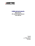
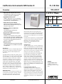
California Instruments MX Series II
15–135 kVA
150–400 V
Overview
0–375 A / Phase
• High Power AC and DC Power Source
Programmable AC and DC power for frequency
conversion and product test applications
208
• Expandable Power Levels
Available output power of 15, 30, and 45 kVA
per unit and multi-unit configurations for power
requirements up to 135 kVA and above
230
400
480
• Single and Three Phase Mode
Phase mode programming on MX30-3Pi and
MX45-3Pi allows switching between single and
three phase output modes
• Arbitrary & Harmonic Waveform
Generation
User defined voltage waveform and
distortion programming
• Regenerative, bidirectional “Green”
Power Solution
Automatic crossover between Source and Sink
power mode offers regenerative capabilities in AC
mode. Regenerate up to 100% of the rated output
power back to the utility grid during sink mode
operation. ( -SNK option )
• Remote Control
Standard RS232C & USB along with optional IEEE488 & LAN Interfaces are available for automated
test applications
Introduction
The MX Series consists of multiple high power AC
and DC power systems that provide controlled
AC and DC output for ATE and product test
applications.
This high power AC and DC test system covers a
wide spectrum of AC and DC power applications
at an affordable cost. Using state-of-the-art PWM
switching techniques, the MX series combines
compactness, robustness and functionality in a
compact floor-standing chassis, no larger than
a typical office copying machine. This higher
power density has been accomplished without
the need to resort to elaborate cooling schemes
or additional installation wiring. Simply roll the
MX15, MX30, or MX45 unit to its designated
location (using included casters), plug it in, and
the MX series is ready to work for you.
Simple Operation
The MX Series can be operated completely from
its menu driven front panel controller. A backlit
LCD display shows menus, setup data, and
read-back measurements. IEEE-488, RS232C,
858.458.0223
USB and LAN remote control interfaces and
instrument drivers for popular ATE programming
environments are available. This allows the MX
Series to be easily integrated into an automated
test system.
For advanced test applications, the programmable
controller version offers full arbitrary waveform
generation, time and frequency domain
measurements, and voltage and current
waveform capture.
Configurations
The MX15 delivers up to 15 kVA of single phase
output. The MX30 delivers up to 30 kVA, and the
MX45 up to 45 kVA. Both operate using single
or three phase output in AC mode. In DC mode,
50% of the AC power level is available. On MX-P
models, AC+DC mode is also supported.
For higher power requirements, the MX90 and
MX135 models are available. Multi cabinet
MX45 systems always operate in three phase
output mode. Available reconfigurable MX90
and MX135 models (-MB designation) provide
multiple controllers which allow separation of the
high power system into two or three individual
MX45 units for use in separate applications. This
ability to reconfigure the system provides an even
greater level of flexibility not commonly found in
power systems.
Product Evaluation and Test
Increasingly, manufacturers of high power
equipment and appliances are required to fully
evaluate and test their products over a wide
range of input line conditions. The built-in output
transient generation and read-back measurement
capability of the MX Series offers the convenience
of a powerful, and easy to use, integrated test
system.
[email protected]
AMETEK
Programmable Power
9250 Brown Deer Road
San Diego, CA 92121-2267
USA
10032012
217
MX Series II
Regenerative, bidirectional “Green”
Power Solution
The MX Series features the ability to both source
and sink current, i.e. bi-directional current
flow. The MX amplifier is designed to reverse
the phase relationship between the AC input
voltage and current in order to feed power back
onto the utility grid. This mode of operation is
particularly useful when testing grid-tied products
that feed energy back onto the grid. Static
Power Converters such as grid-tied and off-grid
photovoltaic inverters are tested for frequency
variations, voltage transients, remove.
Programming sink (-SNK) mode operation
Avionics
With an output frequency range to 819 Hz
(or 1000 Hz with -HF option), the MX Series is
well suited for aerospace applications. Precise
frequency control and accurate load regulation
are key requirements in these applications. The
available IEEE-488 remote control interface
and SCPI command language provide for easy
integration into existing ATE systems. The MX
Series eliminates the need for several additional
pieces of test equipment, saving cost and space.
Instrument drivers for popular programming
environments such as National Instruments
LabView™ are available to speed up system
integration.
Regulatory Testing
As governments are moving to enforce product
quality standards, regulatory compliance testing
is becoming a requirement for a growing number
of manufacturers. The MX Series is designed
to meet AC source requirements for use in
compliance testing such as IEC 61000, 3-2, 3-3,
3-11, 3-12, to name a few.
Choice of voltage ranges
The MX30 and MX45 can be ordered with either
a 150 V RMS Line to Neutral output voltage
range or a 300 V RMS Line to Neutral range. This
provides 3 phase output capability of 260 Vac or
218
520 Vac line to line respectively. If dual output
ranges are required, the programmable range
change option (-R) provides the ability to switch
between both output ranges. Pi version models
offer standard dual voltage ranges.
For applications requiring more than 300 V
L-N (or 520 V L-L), the optional -HV output
transformer provides an additional 400 V L-N
and 693 V L-L output range for use in AC mode
only.
Multi-Box Configurations
For high power applications, two or three
MX45 chassis can be combined to provide 90
to 135 kVA of three phase power. MX90 and
MX135 systems are always configured for three
phase operation. Contact sales for custom
configurations.
High Crest Factor
With a crest factor of up to 3.6, the MX Series
AC source can drive difficult nonlinear loads with
ease. Since many modern products use switching
power supplies, they have a tendency to pull
high repetitive peak currents. The MX30-3Pi can
deliverup to 240 Amps of repetitive peak current
(150 V AC range) per phase to handle three
phase loads.
Remote Control
Standard RS232C & USB IEEE-488 along with
optional LAN remote control interfaces allow
programming of all instrument functions from an
external computer. The popular SCPI command
protocol is used for programming.
Application Software
Windows® application software is included.
This software provides easy access to the power
source’s capabilities without the need to develop
any custom code. The following functions are
available through this GUI program:
• Steady state output control (all parameters)
• Create, run, save, reload and print
transient programs
• Generate and save harmonic waveforms.
• Generate and save arbitrary waveforms.
• Measure and log standard measurements
• Capture and display output voltage and
current waveforms.
• Measure, display, print and log harmonic
voltage and current measurements.
• Display IEEE-488, RS232C, USB and LAN bus
traffic to and from the AC Source to help you
develop your own test programs.
www.ProgrammablePower.com
MX Series II
15–135 kVA
Harmonically distorted waveform.
production environments.
1. Requires PC running WindowsXP™ or Windows 2000™.
Harmonic Waveform Generation
Using the latest DSP technology, the MX
Series programmable controller is capable of
generating harmonic waveforms to test for
harmonics susceptibility. The Windows Graphical
User Interface program can be used to define
harmonic waveforms by specifying amplitude and
phase for up to 50 harmonics. The waveform
data points are generated and downloaded by
the GUI to the AC source through the IEEE-488 or
RS232C bus. Up to 200 waveforms can be stored
in nonvolatile memory and given a user defined
name for easy recall.
All MX-Pi Series configurations offer three phase
waveform generation, allowing independent
phase anomalies to be programmed. It also
allows simulation of unbalanced harmonic line
conditions.
Arbitrary Waveform Generation
Using the provided GUI program or custom
software, the user also has the ability to define
arbitrary AC waveforms. The arbitrary waveform
method of data entry provides an alternative
method of specifying AC anomalies by providing
specific waveform data points. The GUI program
provides a catalog of custom waveforms and also
allows real-world waveforms captured on a digital
oscilloscope to be downloaded to one of the
many AC source’s waveform memories. Arbitrary
waveform capability is a flexible way of simulating
the effect of real-world AC power line conditions
on a unit under test in both engineering and
MX Series - AC and DC Transient Generation
The MX Series controller has a powerful AC
and DC transient generation system that allows
complex sequences of voltage, frequency and
waveshapes to be generated. This further
enhances the MX’s capability to simulate AC line
conditions or DC disturbances. When combined
with the multiphase arbitrary waveform
capabilities, the AC and DC output possibilities
are truly exceptional. Transient generation is
controlled independently yet time synchronized
on all three phases. Accurate phase angle control
and synchronized transient list execution provide
unparalleled accuracy in positioning AC output
events.
Transient programming is easily accomplished
from the front panel where clearly laid out menu’s
guide the user through the transient definition
process.
The front panel provides a convenient listing
of the programmed transient sequence and
allows for transient execution Start, Stop,
Abort and Resume operations. User defined
transient sequences can be saved to non-volatile
memory for instant recall and execution at a
later time. The included Graphical User Interface
program supports transient definitions using
a spreadsheet-like data entry grid. A library
Transient List Data Entry from the front panel.
Harmonic waveform, Fund., 3rd, 5th, 7th, 9th,11th and 13th.
Two hundred user defined waveforms.
858.458.0223
Transient List Data Entry in GUI program.
[email protected]
219
MX Series II
of frequently used transient programs can be
created on disk using this GUI program.
MX Series - Measurement and Analysis
The MX Series is much more than a
programmable AC, DC or AC+DC power source.
It also incorporates an advanced digital signal
processor based data acquisition system that
continuously monitors all AC source and load
parameters. This data acquisition system forms
the basis for all measurement and analysis
functions. These functions are accessible from the
front panel and the remote control interface for
the MX Series (MX15 excluded; uses 2-line display
shown below).
Conventional Measurements [All controllers]
Common AC and DC measurement parameters
are automatically provided by the data acquisition
system. These values are displayed in numeric
form on the front panel LCD display. The
following measurements are available: Frequency,
Vrms, Irms, Ipk, Crest Factor, Real Power (Watts),
Apparent Power (VA) and Power Factor.
Harmonic Analysis
The MX Series provides detailed amplitude and
phase information on up to 50 harmonics of
the fundamental voltage and current (up to 16
kHz in three phase mode) for either one or three
phases. Harmonic content can be displayed
in both tabular and graphical formats on the
front panel LCD for immediate feedback to the
operator (excluding MX15). Alternatively, the
included GUI program can be used to display,
print and save harmonic measurement data. Total
harmonic distortion of both voltage and current is
calculated from the harmonic data.
Waveform Acquisition
The measurement system is based on real-time
digitization of the voltage and current waveforms
using a 4K deep sample buffer. This time domain
information provides detailed information on
both voltage and current waveshapes. Waveform
acquisitions can be triggered at a specific phase
angle or from a transient program to allow
precise positioning of the captured waveform
with respect to the AC source output.
The front panel LCD displays captured waveforms
with cursor readouts (excluding MX15). The
included GUI program also allows acquired
waveform data to be displayed, printed, and
saved to disk.
Acquired Current waveform (MX30/45 Display).
Acquired Voltage waveform (MX30/45 Display).
Measurement data for single phase (MX30/45 Display).
Absolute amplitude bar graph display of current harmonics
with cursor positioned at the fundamental (MX30/45 Display).
Measurement data for all three phases (MX30/45 Display).
Voltage harmonic measurement table display in absolute
values (MX30/45 Display)
Acquired three phase voltage waveforms display on PC.
220
www.ProgrammablePower.com
MX Series II : Specifications
15–135 kVA
Operating Modes
Pi Version
AC, DC and AC+DC
AC Mode Output
Frequency
Range: 16.00-819.0 Hz, -LF Option: 16.00-500.0 Hz, -HF Option: 16.00-1000 Hz (supplemental specifications apply above
819 Hz). Resolution: 0.01 Hz: 16.00 - 81.91 Hz, 0.1 Hz: 82.0 Hz - 819.1 Hz
Phase Outputs
MX15-1/15-1Pi: 1, MX30/45-3Pi: 1 or 3 switchable, Neutral: Floating, Coupling: DC (except for -HV option)
Total Power
MX15-1/1Pi: 15 kVA, MX30-1/3: 30 kVA, MX45-1/3: 45 kVA, MX90: 90 kVA, MX135: 135 kVA
Load Power Factor
0 to unity at full output current
AC Mode Voltage
Voltage Ranges
Range
V Low
V High
Load Regulation
< 0.25 % FS DC to 100 Hz, < 0.5 % FS 100 Hz to 819 Hz
AC
0-150 V
0-300 V
Line Regulation
< 0.1% FS for 10 % line change
AC+DC
0-150 V
0-300 V
External Sense
Voltage drop compensation (5% Full Scale)
Harmonic Distortion (Linear)
Less than 0.5% from 16 - 66 Hz, Less than 1% from 66 - 500 Hz, Less than 1.25% above 500 Hz
DC Offset
< 20 mV
Load Regulation
0.25% FS @ DC - 100 Hz, 0.5% FS > 100 Hz
External Amplitude Modulation
Depth: 0 - 10 %, Frequency: DC - 2 KHz
Voltage slew rate
200 µs for 10% to 90% of full scale change into resistive load, 0.5V / µSec
AC Mode Current
Steady State AC Current @ FS V
Model MX15-1Pi MX30-3Pi / 1Pi MX45-3Pi / 1Pi MX90-3/Pi MX135-3/Pi
V Low 100
66.6/ø / 200
100/ø / 300
200/ø
300/ø
V High 50
33.3/ø / 100
50/ø / 150
100/ø
150/ø
Note: Constant power mode provides increased current at reduced voltage. See chart below
Peak Repetitive AC Current
Up to 3.6 x rms current at full scale voltage
Programming Accuracy
Voltage (rms): ± 0.3 Vrms, Frequency: ± 0.01 % of programmed value, Current Limit: - 0 % to + 5 % of programmed value + 1A, Phase:
< 0.5° + 0.2°/ 100 Hz with balanced load
Programming Resolution
Voltage (rms): 100 mV, Frequency: 0.01 Hz from 16 - 81.91 Hz, 0.1 Hz from 82.0 - 819 Hz, Current Limit: 0.1 A, 3 phase mode,
1.0 A, 1 phase mode, Phase: 0.1°
Constant Power AC Mode - Available Max. AC Current
125%
Current
(RMS) 100%
Full
Power
50%
20%
10%
50%
80%
100%
Voltage (RMS)
Note: Specifications are subject to change without notice. Specifications are warranted over an ambient temperature range of 25°± 5° C. Unless otherwise noted, specifications are per phase
for a sinewave with a resistive load and apply after a 30 minute warm-up period. For three phase configurations, all specifications are for L-N. Phase angle specifications are valid under
balanced load conditions only.
© 2009 AMETEK Programmable Power All rights reserved. AMETEK Programmable Power is the trademark of AMETEK Inc., registered in the U.S. and other countries. Elgar, Sorensen,
California Instruments, and Power Ten are trademarks of AMETEK Inc., registered in the U.S.
858.458.0223
[email protected]
221
MX Series II : Specifications
Measurement
Measurements - Standard
(AC Measurements)
Parameter
Frequency
Range
16-100 Hz
100-820 Hz
0.01% +
0.05 V + 0.15 A +
0.01 Hz
0.02%
.02%
Accuracy*
(±)
RMS
Voltage
0-400 V
Resolution* 0.01 Hz /
0.1 Hz
RMS
Current
0-160 A
Peak
Current
0-400 A
Crest
Real
Factor
Power
0.00-6.00 0-15 kW
Apparent
Power
0-15 kVA
Power
Phase
DC
Factor
Voltage
0.00-1.00 0.0-360.0 0-400 V
DC
Current
0-160 A
Power
0.5 V
0.5 A
0.15 kW
10 mV
10 mA
10 W
0.15 A + 0.05
0.02%
30 W +
0.1%
30 VA +
0.1%
0.01
2.0°
0.1 V +
0.3 A +
0.3 A +
0.05
0.02%
0.02%
0.02%
10 mV
10 mA
10 mA
0.01
60 W +
0.1%
10 W
60 VA +
0.1%
10 VA
0.02
3.0°
0.01
0.1°
Power
* Measurement system bandwidth = DC to 6.7 kHz. Accuracy specifications are valid above 100 counts. Current and Power Accuracy and Range specifications are
times three for MX90, MX135 or MX30/45-3Pi in single phase mode. PF accuracy applies for PF > 0.5 and VA > 50 % of range
Measurements - Harmonics
(Pi controller only)
Parameter
Frequency Fundamental Harmonics
Phase
Voltage
Current
Range
16.00-1000.0 Hz / 32.00 Hz - 16 kHz
0.0 - 360.0°
Fundamental Harmonics 2-50
Fundamental Harmonics 2-50
Accuracy* (±)
0.03% + 0.03 Hz / 0.01 Hz
2° typ.
750 mV 0.3% + 750 mV+0.3% /1 kHz
0.5 A / 0.3% + 150 mA +0.3% /1 kHz
Resolution
0.01 Hz
0.5°
10 mV / 10 mV
100 mA / 100 mA
* Accuracy specifications are valid above 100 counts. Accuracy specifications are for three phase mode. Harmonics frequency range for MX30/45-3Pi in single phase
mode is 32 Hz - 48 kHz
DC Mode Output
Power
Maximum DC power at full scale of DC voltage range. MX15-1Pi: (10 kW), MX30-3Pi: (6.5 kW per output, 3 outputs. 20 kW in
1 channel mode), MX45-3Pi: (10 kW per output, 3 outputs. 30 kW in 1 channel mode)
Voltage Ranges
Range: Low (0 - 200 V), High (0 - 400 V)
Output Accuracy
± 1 Vdc
Load Regulation
< 0.25 % FS
Line Regulation
< 0.1% FS or 10 % line change
Ripple
< 2 Vrms Lo Range, < 3 Vrms Hi Range
Max DC Current @ FSV per output
Model
MX15-1Pi MX30-3Pi / 1Phs MX45-3Pi / 1Phs MX90-3/Pi MX135-3/Pi
V Low
50
V High 25
33.3 / 100
50 / 150
100
150
16.6 / 50
25 / 75
50
75
Note: Constant power mode provides increased current at reduced voltage. See chart on previous page
Current Limit
Programmable from 0 A to max. current for selected range
AC+DC Mode Output
Output (Pi) Power
Maximum current and power in AC+DC mode is same as DC mode
Protection
Over Load
Constant Current or Constant Voltage mode
Over Temperature
Automatic shutdown
Storage
Non Volatile Mem. storage
16 instrument setups, 200 user defined waveforms [Pi only]
Waveforms
Waveform Types
Std: Sine, Pi: Sine, Square, Clipped sine, User defined
User defined waveform storage
Four groups of 50 user defined arbitrary waveforms of 1024 points for a total of 200. One group can be active at a time
System Interface
Inputs
Remote shutdown, External Sync, Clock/Lock
Outputs
Function Strobe / Trigger out, Clock/Lock
Remote Control (Pi standard with -P option)
222
IEEE-488 Interface
IEEE-488 (GPIB) talker listener. Subset: AH1, C0, DC1, DT1, L3, PP0, RL2, SH1, SR1, T6, IEEE-488.2 SCPI Syntax
RS232C Interface
9 pin D-shell connector (Supplied with RS232C cable)
LAN ( option )
Ethernet Interface: 10BaseT, 100BaseT, RJ45
USB
Version: USB 1.1; Speed: 460 Kb/s maximum
Output Relay
Push button controlled or bus controlled output relay
Output impedance
( not available with -SNK Option )
Programmable Z available on MX30-3Pi and MX45-3Pi in 3 phase mode only. Specifications apply at 50 Hz fundamental.
Resistive: 1 - 200 mOhm, Inductive: 15 - 200 uH
www.ProgrammablePower.com
MX Series II : Specifications
15–135 kVA
AC Input
Voltage
Must be specified at time of order. All inputs are L-L, 3ø, 3 wire + Gnd. 208 ± 10% VAC, 230 ± 10% VAC, 400 ± 10% VAC,
480 ± 10% VAC
Input Line Current (per phase)
Current (MX15):
Current (MX30/45):
V L-L
208
230
400
480
St State
58.3 ARMS 52.3 ARMS 30 ARMS 25 ARMS
V L-L
208
230
400
480
St State 116/175 ARMS 105/157 ARMS 60/90 ARMS 50/75 ARMS
Distortion: < 8 % at full power < 20 % below 35 % of power
Line Frequency
47 - 63 Hz
Efficiency
85 % typical
Power Factor
0.95 typical
AC Service
Inputs/Outputs
MX30/MX45: Front access, cables routed through rear panel, exit in back. MX15: Rear Access
Regulatory
IEC61010, EN50081-2, EN50082-2, CE EMC and Safety Mark requirements
EMI
CISPR 11, Group1 , Class A
Connectors
AC Input & Output terminal block behind front cover, IEEE-488 (GPIB) connector (rear panel), 9 pin D-Shell RS232C connector*, (rear
panel), Remote voltage sense terminal block (rear panel), System Interface Connector, DB-37 (rear panel). *RS232 DB9 to DB9 cable
supplied
Physical Dimensions
MX30/MX45 Dimensions
Height: 50.0” (1270 mm), Width: 28.75” (731 mm), Depth: 34.5” (876 mm)
MX30/MX45 Weight
Chassis: Net: 1150 lbs / 522 Kg, Shipping: 1231 lbs / 560 Kg, Amp Module: Net: 63 lbs / 29 Kg
MX15 Dimensions
Height: 31.75” (806 mm), Width: 24.0” (610 mm), Depth: 28.0” (711 mm)
MX15 Weight
Chassis: Net: 600 lbs / 272 Kg, Shipping: 681 lbs / 309 Kg, Amp Module: Net: 63 lbs / 29 Kg
Chassis
MX30/MX45: Casters and forklift openings. MX15: Casters
Vibration and Shock
Designed to meet NSTA project 1A transportation levels. Units are shipped in wooden crate with forklift slots
Air Intake/Exhaust
Forced air cooling, front air intake, rear exhaust
Operating Humidity
0 to 95 % RAH, non condensing
Temperature
Operating: 0 to 40° C (30° C max in CP mode), Storage:
-20 to +85° C
Programmable controller versions with dual voltage ranges
Model
AC Output Power
Phase Outputs
AC/DC Voltage Range
Controller
MX15-1Pi
15kVA
1
150/200 & 300/400
Programmable
MX30-3Pi
30 kVA
1&3
150/200 & 300/400
Programmable
MX45-3Pi
45 kVA
1&3
150/200 & 300/400
Programmable
MX90-3Pi
90 kVA
3
150/200 & 300/400
Programmable
MX135-3Pi
135 kVA
3
150/200 & 300/400
Programmable
Pi models include IEEE-488, RS232C & USB interfaces, Advanced measurements, arbitrary waveform generation. Phase mode switching on MX-30/45-3Pi.
-MB Option
Model
AC Output Power
Phase Outputs
AC/DC Voltage Range
Controller
MX90-3Pi-MB
90 kVA
3
150/200 & 300/400
Dual MX45-3Pi
MX135-3Pi-MB
135 kVA
3
150/200 & 300/400
Triple MX-45-3Pi
Reconfigurable systems can be separated into stand-alone MX45-3Pi models or combined for higher power levels.
Steady State AC RMS Current in Regeneration Mode ( -SNK Option )
Model
MX15-1Pi
MX30-3Pi
MX45-3Pi
MX60-3Pi
MX90-3Pi
MX135-3Pi
V Low
100A
66.6/Ø / 200
100A/Ø/300
133.3/Ø
200/Ø
300/Ø
V High
50A
33.3/Ø / 100
50A/Ø/150
66.6/Ø
100/Ø
150/Ø
858.458.0223
[email protected]
223
MX Series
Model
Refer to table shown for model numbers and
configurations.
-413*IEC 1000-4-13 Harmonics &
Interharmonics test firmware.
-704 Mil Std 704 A - F test - firmware/ software.
Supplied with
Standard:User Manual on CD ROM.
Pi version: User/Programming Manual and Software
on CD ROM. RS232C serial cable.
-ABD ABD0100.1.8 Test Option.
-AMDAirbus AMD24 Test
-A350Airbus Test Software
Input Voltage Settings
Specify input voltage (L-L) setting for each MX
system at time of order:
208Configured for 208 V ±10 % L-L,
4 wire input.
230Configured for 230 V ±10 % L-L,
4 wire input.
400Configured for 400 V ±10 % L-L,
4 wire input.
480 Configured for 480 V ±10 % L-L,
4 wire input
-B787Boeing 787 Test Software
Standard Model Options
Specify output range on standard models. All
range values shown are Line to Neutral.
-WHMWatt-Hour Measurement option.
-HV Adds 400 V L-N AC-only output range.
-LF Limits max. frequency to 500 Hz.
-HF Increases max. frequency to 1000 Hz.
-XV Adds other AC-only output range.
Consult factory.
-LKMClock/Lock Master
-LKSClock/Lock Auxiliary
-SNKBidirectional auto source and sink mode.
Offers up to 100% power sink capability
in AC mode of operation..
- 150 Configured for 150 V AC and
200 V DC output ranges.
Packaging and Shipment
- 300Configured for 300 V AC and
400 V DC output ranges.
All MX systems are packaged in re-usable protective
wooden crates for shipment.
Pi Model Options
-160RTCA/DO-160D, DO-160E, and
EUROCAE test firmware.
Feature Comparison
Model
Pi
-411*IEC 1000-4-11 test firmware.
AC mode
X
DC mode
X
- LFLimits maximum frequency to 500 Hz.
AC+DC mode
X
- PIEEE-488 & RS232C Interface Adds programming, Windows & RS232 Cable.
Dual V Range
X
Transient programming
X
-LANEthernet Interface.
Arbitrary waveforms
X
Measurements
X
- HFIncreases max frequency to 1000 Hz.
Harmonic measurements
X
- RRange change. Provides 150/200 & 300/ 400 AC/DC output ranges. (Std. MX15)
1 or 3 Phase mode
MX15 Dimensions - single chassis
X
Waveform acquisition
MX30/45-3Pi
X
IEEE / RS232
MX30/MX45 Dimensions - single chassis
28.75
[730.25]
31.75
[806.45]
48.125
[1222.4]
00
28. .20]
1
1
7
[
Rear View
224
0
24.0 0]
.8
[609
Front View
Rear View
www.ProgrammablePower.com
Front View
1.95
[49.53]