1
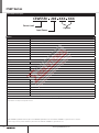
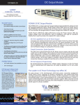
Test Equipment Solutions Datasheet
Test Equipment Solutions Ltd specialise in the second user sale, rental and distribution of
quality test & measurement (T&M) equipment. We stock all major equipment types such as
spectrum analyzers, signal generators, oscilloscopes, power meters, logic analysers etc from
all the major suppliers such as Agilent, Tektronix, Anritsu and Rohde & Schwarz.
We are focused at the professional end of the marketplace, primarily working with customers
for whom high performance, quality and service are key, whilst realising the cost savings that
second user equipment offers. As such, we fully test & refurbish equipment in our in-house,
traceable Lab. Items are supplied with manuals, accessories and typically a full no-quibble 2
year warranty. Our staff have extensive backgrounds in T&M, totalling over 150 years of
combined experience, which enables us to deliver industry-leading service and support. We
endeavour to be customer focused in every way right down to the detail, such as offering free
delivery on sales, covering the cost of warranty returns BOTH ways (plus supplying a loan
unit, if available) and supplying a free business tool with every order.
As well as the headline benefit of cost saving, second user offers shorter lead times, higher
reliability and multivendor solutions. Rental, of course, is ideal for shorter term needs and
offers fast delivery, flexibility, try-before-you-buy, zero capital expenditure, lower risk and off
balance sheet accounting. Both second user and rental improve the key business measure of
Return On Capital Employed.
We are based near Heathrow Airport in the UK from where we supply test equipment
worldwide. Our facility incorporates Sales, Support, Admin, Logistics and our own in-house
Lab.
All products supplied by Test Equipment Solutions include:
- No-quibble parts & labour warranty (we provide transport for UK mainland addresses).
- Free loan equipment during warranty repair, if available.
- Full electrical, mechanical and safety refurbishment in our in-house Lab.
- Certificate of Conformance (calibration available on request).
- Manuals and accessories required for normal operation.
- Free insured delivery to your UK mainland address (sales).
- Support from our team of seasoned Test & Measurement engineers.
- ISO9001 quality assurance.
Test equipment Solutions Ltd
Unit 8 Elder Way
Waterside Drive
Langley
Berkshire
SL3 6EP
T: +44 (0)1753 596000
F: +44 (0)1753 596001
Email: [email protected]
Web: www.TestEquipmentHQ.com
California Instruments CSW Series
High Performance Programmable AC and DC Power Source
5550–33300 VA
156–312 V
8–288 A
• Combination AC and DC Power Source
• 40-5,000Hz Output Frequencies
• Arbitrary and Harmonic Waveform Generation
208
• Built-In Digital Power Analyzer
230
400
• Scope Capture Capability
• Power Programming Software
• Constant Power Mode
• Multi-Box Option
Introduction
Applications
The CSW Series represents a new generation of
AC/DC power sources that address the increasing
demands on test equipment to perform additional
functions at a lower cost. By combining a flexible
AC/DC power source with a high performance
power analyzer, the Compact CSW Series is
capable of handling complex applications that
have traditionally required multiple systems. The
sleek integrated approach of the CSW avoids
cable clutter that is commonly found in test
systems. All connections are made internally and
the need for digital multimeters, power harmonics
analyzers, and current shunts or clamps is
eliminated.
Since many components in the CSW are shared
between the AC/DC source and the power
analyzer, the total cost of the integrated system is
less than the typical cost of a multiple unit system.
Easy to use controls
The CSW Series is DSP controlled and can be
operated from an easy to use front panel keypad.
Functions are grouped logically and are directly
accessible from the keypad. This eliminates the
need to search through various levels of menus
and/or soft keys. A large analog control knob
can be used to quickly slew output parameters.
This knob is controlled by a dynamic rate change
algorithm that combines the benefits of precise
control over small parameter changes with quick
sweeps through the entire range.
858.458.0223
The CSW is designed for testing today’s
complex electronics, including avionics,
telecommunications and commercial electronics
requiring low profile, light weight power supplies
Other applications include:
• Testing for real world power conditions using
different waveforms on all 3 phases (including
DC)
• Load susceptibility testing with sequence or
event programming and multiple voltage
harmonics
• Power line disturbance simulation testing
• MIL-STD-704, DO-160, B787 and ABD100
avionics testing
• Power supply testing for AC-DC, DC-DC
converters and UPS’s
• Transients on 12 & 24 VDC for automotive
applications
AC, DC or AC+DC Output
A direct coupled, transformerless design allows
AC and DC on separate phases or on the same
phase. The CSW can be used as a true DC power
supply. High DC content waveforms (up to
312 volts) can be created with no derating of
output power, even with 100% reactive loads,
eliminating the need for a separate DC supply.
Waveform programming is easily accomplished
using the Graphical Users Interface software.
Waveforms can be uploaded and modified from
a digital scope. The waveforms can then be
downloaded to the CSW and output to precisely
simulate real-world conditions.
[email protected]
AMETEK
Programmable Power
9250 Brown Deer Road
San Diego, CA 92121-2267
USA
01172014b
167
CSW Series
Flexability in Power Ranges
The CSW Series is based on a 5,550VA power
source. The CSW features selectable Single
or Three Phase output via front panel menu
selection or via remote control interface. Utilizing
Master / Auxilary arrangement the CSW offers
the flexibility to paralled up to power levels of
33,300VA
High Crest Factor
With a crest factor of up to 3.25:1; the CSW
Series AC source can drive difficult nonlinear
loads with ease. Since many modern products
use switching power supplies, they have a
tendency to pull high repetitive peak currents.
The CSW5550 can deliver up to 38.5 Amps of
repetitive peak current (156 V range) per phase
Harmonic Waveform Generation
Using the latest DSP technology, the CSW Series
programmable controller is capable of generating
harmonic waveforms to test for harmonics
susceptibility. The Windows Graphical User
Interface program can be used to define harmonic
waveforms by specifying amplitude and phase for
up to 50 harmonics. The waveform data points
are generated and downloaded by the GUI to
the AC source through the remote interface. Up
to 200 waveforms can be stored in nonvolatile
memory and given a user defined name for easy
recall.
Harmonically distorted waveform.
Using the provided GUI program or custom
software, the user also has the ability to define
arbitrary AC waveforms. The arbitrary waveform
method of data entry provides an alternative
method of specifying AC anomalies by providing
specific waveform data points. The GUI program
provides a catalog of custom waveforms and also
allows real-world waveforms captured on a digital
oscilloscope to be downloaded to one of the
many AC source’s waveform memories. Arbitrary
waveform capability is a flexible way of simulating
the effect of real-world AC power line conditions
on a unit under test in both engineering and
production environments.
CSW Series - AC and DC Transient Generation
The CSW Series controller has a powerful AC
and DC transient generation system that allows
complex sequences of voltage, frequency and
waveshapes to be generated. This further
enhances the CSW’s capability to simulate
AC line conditions or DC disturbances. When
combined with the multiphase arbitrary waveform
capabilities, the AC and DC output possibilities
are truly exceptional. Transient generation is
controlled independently yet time synchronized
on all three phases. Accurate phase angle control
and synchronized transient list execution provide
unparalleled accuracy in positioning AC output
events.
Transient programming is easily accomplished
Transient List Data Entry from the front panel.
Arbitrary Waveform Generation
Harmonic waveform, Fund., 3rd, 5th, 7th, 9th,11th and 13th.
Two hundred user defined waveforms.
Transient List Data Entry in GUI program.
168
www.ProgrammablePower.com
CSW Series
5550–33300 VA
from the front panel where clearly laid out menu’s
guide the user through the transient definition
process.
The front panel provides a convenient listing
of the programmed transient sequence and
allows for transient execution Start, Stop, Abort
and Resume operations. User defined transient
sequences can be saved to non-volatile memory
for instant recall and execution at a later time.
The included Graphical User Interface program
supports transient definitions using a spreadsheetlike data entry grid. A library of frequently used
transient programs can be created on disk using
this GUI program.
Harmonic Analysis
The CSW Series provides detailed amplitude
and phase information on up to 50 harmonics
of the fundamental voltage and current (up to
16 kHz). Harmonic content can be displayed
in both tabular and graphical formats on the
front panel LCD for immediate feedback to the
operator. Alternatively, the included GUI program
can be used to display, print and save harmonic
measurement data. Total harmonic distortion of
both voltage and current is calculated from the
harmonic data.
Acquired Current waveform (CSW Display).
Acquired Voltage waveform (CSW Display).
Measurement data for single phase (CSW Display).
Measurement data for all three phases (CSW Display).
Absolute amplitude bar graph display of current harmonics
with cursor positioned at the fundamental (CSW Display).
Acquired three phase voltage waveforms display on PC.
Voltage harmonic measurement table display in absolute
values (CSW Display)
Waveform Acquisition
The measurement system is based on real-time
digitization of the voltage and current waveforms
using a 4K deep sample buffer. This time domain
information provides detailed information on
both voltage and current waveshapes. Waveform
acquisitions can be triggered at a specific phase
angle or from a transient program to allow precise
positioning of the captured waveform with
respect to the AC source output.
The front panel LCD displays captured waveforms
with cursor readouts. The included GUI program
also allows acquired waveform data to be
displayed, printed, and saved to disk.
858.458.0223
Multi-Box Option
In many applications high power is required for
a small portion of the testing while a majority of
the tests are performed at reduced power levels.
The controller architecture of the CSW provides
the end-user with a wide array of configuration
options that often eliminate the need to purchase
different AC or DC power systems to meet a
variety of applications. The Multi-Box option is
available which allows multiple channel systems
to be separated into individually controlled stand
alone power sources. By simply connecting the
interface cable between multiple sources the
hardware automatically sets itself to the system
configuration offering Plug and Play performance.
There is no need to modify configuration settings
from the front panel or hardware jumpers located
internally to the source. The multi-box feature
is ideal for end-users planning to increase power
levels or separate a system into multiple smaller
sources.
[email protected]
169
CSW Series : Product Specifications
Input
Voltage Ranges
Factory configured 187 to 264 Vrms, 3ø L-L (3 wire), or 342 to 457 Vrms, 3ø L-L (4 wire). A chassis ground is also required.
Power Factor
PFC Input, 0.99PF
Frequency Range
47 to 440 Hz
Efficiency
70% min, at full load
Ride Through
10 ms minimum
Output
Power
5550 VA: 1ø or 3ø (systems up to 33,000 VA)
AC or DC Output Voltage
0 to156 Vrms L-N, low range; 0 to 312 Vrms L-N, high range
Current Per Phase
16A to 115V in 156V range; 8A to 230V in 312V range per, 1850 VA module.
Power Factor of Load
0 lagging to 0 leading (0-unity)
Crest Factor
3.25:1 (peak output current to rms output current))
Frequency Range
Specifications apply DC, 40Hz to 5kHz. For output frequencies greater than 1 kHz, the max slew rate
allowed is 1 kHz per second.
Max Total Harmonic Distortion
(Full Linear Load or No Load): 0.25% max, 40 to 100 Hz; 0.5% max to 500 Hz; and 1% max to 1 kHz plus 1%/kHz to 5 kHz
AC Noise Level
>60 dB rms below full output voltage
Amplitude Stability With Remote Sense
±0.1% of full scale over 24 hours at constant line, load and temperature
Line Regulation
(DC, or 40 Hz to 5 kHz): ±0.015% of full scale for a ±10% input line change
Load Regulation
±0.025% of full scale voltage for a full resistive load to no load; above 1 kHz, add ±0%/kHz
Voltage Accuracy
±0.1% of range. Above 1 kHz, add 0.2%/kHz. Add ±0.1% of full scale for “AC PLUS DC” mode. Valid for 5 to 156 Vrms and
10 to 312 Vrms at 25°C
Voltage Resolution
1mV (0.1V) Full Scale
Frequency Accuracy
±0.01% at 25°C ±0.001%/°C
Frequency Resolution
40 Hz to 81.91 Hz (0.01 Hz)
81.90 Hz to 819 Hz (0.01 Hz)
820 Hz to 5000 Hz (1 Hz)
Phase Accuracy, Phase-to-Phase
Balanced Linear Resistive Load
±1% of Programmed value
Phase Angle Resolution
0.1°
Remote Output Voltage Sense
5 Vrms total lead drop, max
Common Intput and Outputs
170
Remote Inhibit
A logic Low or High contact closure input to inhibit the outputs
External Amplitude Modulation
0 to 5 VRMS provides 0 to 20% output amplitude modulation (±2% of full scale output).
External Drive Input
Acts as Amplifier, 0 to 5 VRMS (DC to 5 kHz) or ±5 VDC input for zero to full scale programmed voltage output
(±2% of full scale output). Individual inputs for an external signal for each of the three phases.
Remote Programming Voltage
0 to ±7.07 VDC provides zero to full scale programmed voltage output
(±2% of full scale output).
External Input Impedance
40K (ohm symbol) for each of the three inputs.
Externaly Sync
External Sync allows the output frequency of the AC source to be synchronized to an external TTL level clock signal.
LKM
Clock and Lock Master. Enables synchronizing outputs of two or more California Instruments sources, one acts as master.
LKS
Clock and Lock Auxiliary
Front Panel Trigger, BNC Connector
Output available at the front panel BNC connector that provides a negative going pulse for any programmed voltage or frequency
change. The trigger can be reassigned as an output when running list transients.
Front Panel Phase A, B and C,
BNC connectors
These three outputs are representive of the programmed output waveform, magnitude and frequency. 0 to 4.86 Vrms represents 0 to
a full-scale output voltage.
www.ProgrammablePower.com
CSW Series : Product Specifications
5550–33300 VA
Environmental
Operating Temperature
0°C to 45°C (32°F to 113°F)
Storage Temperature
-40°C to 70°C (-40°F to 158°F)
Cooling
Air is drawn in from the top, bottom, and sides and exhausted through the rear
Humidity (Non-condensing)
0 to 85% at 25°C (77°F); derate to 50% at 40°C (104°F)
Altitude
Operating 10,000 ft, non operating 40,000 ft
Physical
Dimensions
Width: 19” (483 mm)
Height: 8.75” (222 mm)
Depth: 23.5” (597 mm)
Weight
CSW 5550 - 127 lbs (57.5 kg)
Shipping Weight - US
CSW - 160 lbs (72 kg)
Note
Multi Chassis systems, dimension and weight are approximately x2, x3, x4, x5 and x6 CSW Specifications
Measurements
Measurements - Standard
(AC Measurements)
Parameter
Frequency
Phase
Voltage (AC)
Current (AC rms)
Real Power
Range
40-81.91 Hz
82.0-819.1 Hz
> 819 Hz
40-100 Hz
100-1000 Hz
0-300 V
0-50 A
0.1% + 1 digit
0.5°
2°
0.1° / 1°
0.5% + 250 mV 0.1% + 150 mA
0.1% + 50 mA
10 mV
1 mA
Accuracy* (±)
1 ø mode (-1)
3 ø mode (-3)
Resolution*
.01 Hz / 0.1 Hz / 1 Hz
0-6 kW
Apparent
Power
0-6 kVA
Power
Factor
0.00-1.00
0.15% + 9 W
0.15% + 3 W
1W
0.15% + 9 VA
0.15% + 3 VA
1 VA
0.03
0.01
0.01
* Accuracy specifications are in % of reading and apply above 100 counts. For multi-chassis configurations, current, power range and accuracy specifications are
times three. Power factor accuracy applies for PF > 0.5 and VA > 50% of max. Frequency measurement specification valid for output > 30 Vrms.
Constant Power AC Mode
Current Frequency Rating Chart for 156VAC Range (range in 3 phase mode)
Harmonic Measurements
Parameter
Range
Accuracy ( ± )
Resolution
Frequency fundamental
16.00 - 1000 Hz
2 counts
0.01 Hz to 1 Hz
Frequency harmonics
32.00 Hz - 16 kHz
2º typ.
0.5º
Voltage
Fundamental
0.25V
0.01V
Harmonic 2 - 50
0.25V + 0.1% + 0.1%/kHz
0.01V
Current
Fundamental
0.05A
0.01A
Harmonic 2 - 50
0.05A + 0.1% + 0.1%/kHz
0.01A
Harmonics frequency range in three-phase mode is 32 Hz - 16 kHz. Accuracy specifications are multiplied by the number of power sources in multi-source systems with the
3-phase (3Ø) or the number of sources times 3 in the 1-phase (1Ø) mode . Measurement bandwidth is limited to 16 Khz.
Model
Multiplier 3Ø/1 Ø
858.458.0223
CSW5550
CSW11100
CSW16650
CSW22200
CSW27750
CSW33300
1/3
2/6
3/9
4/12
5/15
6/18
[email protected]
171
CSW Series : Product Specifications
Protection And Safety
Overvoltage Shutdown
172
Programmable for 15V to 255V peak, 156V range; 30V to 510V peak, 312V range
Programmable Current Limit Shutdown
Settable to 0.01 ARMS Resolution
Programmable Current Limit
with Timed Shutdown
Settable to 1% of range: the timeout is settable from 100 ms to 10s.
Over temperature Shutdown
Automatic, not programmable
Regulatory Compliance
• EN 61010
• EN 55011
• UL 3111
• EN 50082-2
• EN 61000-4-3, EN 61000-4-4
• FCC Part 15, Class A
• CE Mark
Designed to meet:
• EN 61010
• EN 55011
• UL 3111
• EN 50082-2
• EN 61000-4-3, EN 61000-4-4
• FCC Part 15, Class A
www.ProgrammablePower.com
CSW Series : Product Diagram
5550–33300 VA
19” (483mm)
8.71”
(221 mm)
Front View
16.90”
8.620”
Rear View
8.620
16.90”
6.325
1.810
5.330
2.371”
1.065 DIA
FOR INPUT
WIRING
.875 DIA
FOR SENSE
WIRING
1.063 DIA
FOR OUTPUT
WIRING
A
8-32UNC-2B
A = ACCURIDE
SLIDE MOUNTING
23.440”
13.250
21.069”
A
4.875
A
4.100
2.680
Top View
858.458.0223
Side View
[email protected]
173
CSW Series
Model Number Description
CSW5550
208 XXX XXX
Power Level
Options
Input Power
Options
Options Code
Description
-LAN
LXI Ethernet LAN Interface (Rj45 Connector)
-LKM
Clock/Lock Master
-LKS
Clock/Lock Auxiliary
-413
IEC61000-4-13 Harmonics and Interharmonics test firmware and hardware.
-411
IEC61000-4-11 test firmware. See also EOS1/3.
-WHM
Watt-Hour Measurement option.
-MB
Multi-Box. Adds controller to auxiliary chassis of multi-chassis systems
-SW
SCPI Command Firmware (Simulates the Elgar SW Series) Not all commands are supported. Please contact factory for details.
Input Options
-400
342-457 Volt Line to Line AC input.
Output Options
-LF
Limits output frequency to 500 Hz.
-FC
Modifies output frequency control to ± 0.15%
Cabinet Options
-RMS
Rackmount Slides. Recommended for rack mount applications.
C prefix
Cabinet System. Installed and pre-wired in 19” cabinet.
Avionics Test Routine Options
-ABD
Airbus Directive 0100.1.8 tests.
-AMD
Airbus AMD24 tests.
-A350
Airbus A350 tests.
-AIRB
Airbus ABD0100.1.8, AMD 24 and A350 combination test software suite
-B787
Boeing 787B3-0147 tests.
-704F
Mil. Std. 704A-F tests
-160
RTCA/DO-160D, Change 2, EuroCAE-14D and Airbus test firmware.
* Note Reference the Avionics Test User Manual P/N 4994-971 for a complete listing of performance capabilities.
All specifications are subject to change without notice.
© 2014 AMETEK Programmable Power All rights reserved. AMETEK Programmable Power is the trademark of AMETEK Inc., registered in the U.S. and other
countries. Elgar, Sorensen, California Instruments, and Power Ten are trademarks of AMETEK Inc., registered in the U.S.
174
www.ProgrammablePower.com