1
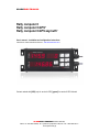
SPARKELECTRONICS Rally computer 6 Rally computer 6.GPS* Rally computer 6.GPS azymuth* User’s manual - Installation and configuration instructions. (with links to video instructions online at : www.rallycomputer.com ) Content marked with [GPS] only for version 6.GPS, [gpsazi] for version 6.GPS Azimuth SPARKELECTRONICS Robert Skierski, Biuro: 01-424 Warszawa, Al. Prymasa Tysiąclecia 78a, tel / fax : 022 836-24-51 www.rajdowe-haldy.pl SPARKELECTRONICS Tripmeter’s description Rally Computer tripmeter 6 is a professional device used in flat, off-road and navigation rallies. The device is very flexible in use enabling the selection and adjustment of the measured parameters to the specifics of the given rally. The user can configure the displays its own way to show the chosen functions. Aluminum waterproof case provides protection from external factors. The measurements results are presented on a super-bright red LED displays. The tripmeter is equipped with a 7-button keypad, where keys are permanently assigned to the main measuring functions. Features Precise distance measurement using two independent counters TRIP and ODO with a 10m accuracy. Direct ODO correction Backward counting when the vehicle moves backwards. The switch is done automatically after changing to reverse gear. (Note ! The grey cable needs to be connected to the sensor or the reverse light bulb). Precise time measurement using two independent timers. One of them works as stopwatch. The other one works as countdown timer with possibility of deducting from pre-set values . Current speed measured with 1 km/h accuracy. Indication of the average and maximum speed for the section of the road up to 1 km/h accuracy. Vehicle’s voltage indication. Adjustable display brightness and backlit keys for comfortable measurements during night sections. Memory with up to 10 wheel calibration settings, corresponding to different tyre sizes Connection to an external switch Possibility to work with external repeating device, for example Rally Computer 3 [gps] leading to target by azimuths. [gpsazi] routing waypoints based on the course and distance to destination Installation instructions The tripmeter should be installed in a visible place, allowing easy and quick access to the front panel. The tripmeter has been supplied with mounting brackets for easier attachment. Do not remove the brackets completely as this can unseal the tripmeter housing. When connecting the power supply make sure that the voltage source is reliable and stable with the voltage within the range between 8 to 30 V. Please refer to diagram using the link below : http://www.rallycomputer.com/support/how-to-connect.html SPARKELECTRONICS Robert Skierski, Biuro: 01-424 Warszawa, Al. Prymasa Tysiąclecia 78a, tel / fax : 022 836-24-51 www.rajdowe-haldy.pl SPARKELECTRONICS NOTE !!! Switching off the tripmeter does not disconnect it completely from the power supply. The tripmeter still consumes electricity (reduced to a minimum). When the tripmeter is not used for a long period, it is recommended to disconnect it from the car installation. This will prevent the battery from discharging. It is best to install an external switch that fully disconnects the tripmeter from its power supply. Do not install the tripmeter in places where it may be damaged or work improperly, e.g. on airbaigs, or air outlets. Tripmeter’s appearance Tripmeter is equipped with three independent displays. For the purpose of this instruction, we call them respectively: A (top left) B (top right) C (bottom) Basic information Rally Computer 6 can operate in three measuring modes. Modes can be selected from the startup screen by pressing [F1]. If no mode is selected, the tripmeter will work in DIST mode as default. Mode description. o o o DIST mode - short interval TRIPs, quick deletions while still having access to other functions STAGE mode - to measure the total distance while still having access to other functions AZIMUTH mode - to navigate to the target based on azimuth while still having access to other functions SPARKELECTRONICS Robert Skierski, Biuro: 01-424 Warszawa, Al. Prymasa Tysiąclecia 78a, tel / fax : 022 836-24-51 www.rajdowe-haldy.pl SPARKELECTRONICS Mode Mode light DIST Each light indicates its basic function. STAGE AZIMUTH Each light indicates Its basic function. All 4 lights flash Briefly. Each light indicates Its basic function. Purpose Operations When you need to measure or quickly delete the TRIP route From the Start Screen, press [F1] followed by [OK] – the screen will show DIST When you need to measure a STOPWATCHED section When you need get to the target based on azimuth. From the Start Screen, press [F1] until STAGE shows and then press [OK] From the Start Screen, press [F1] until AZIM shows and then press [OK] Switching ON/OFF After switching the power on the tripmeter: o will display the current settings and begins work in AUTODIST mode (only when if it was earlier switched off while not making measurements, or when it is switched on for the first time) In window A -Tripmeter will show if it’s working in Master or Slave mode (when working with a repeating device) In window B – Tripmeter will show currently selected CAL value o will continue previous measurments (only if it was earlier switched off while making measurements). To switch off the tripmeter at any time, press the [F1] key for 12 sec. While turning itself off the tripmeter will show the start screen after 3 seconds , and then after 7 seconds will present the serial number and version and finally will switch off. Rally computer 6 will turn off automatically after 1 minute if no power power is supplied on the yellow wire. Switching off the tripmeter does not disconnect it completely from the power supply! SPARKELECTRONICS Robert Skierski, Biuro: 01-424 Warszawa, Al. Prymasa Tysiąclecia 78a, tel / fax : 022 836-24-51 www.rajdowe-haldy.pl SPARKELECTRONICS Basic configuration To enter the configuration menu you need to: go to the start screen: press and hold [CLR] for 3 seconds restart the device from the keypad: from the start screen position simultaneously press [SPEED], [CLR] and [OK] After the reset, all displays will show the 88888 and: - In window A -Tripmeter will show if it’s working in Master or Slave mode (when working with a repeating device) In window B – Tripmeter will show currently selected CAL value At this point press 3 x [F1] and 1 x [OK]. Then CONF will show on the display. To select a function press [F1], and confirm with [OK]. To change the value press [F1] and then confirm by pressing [OK]. The change will be confirmed by a quick screen flash. To exit press [CLR]. Available functions: 1. Master/Slave setting – the display shows TYPE select this function to choose between Master, Slave and Auto mode a. Master – this mode will always take control over the other device. It will send data to the repeating device b. Slave – in this mode the device will works as “slave” to the other device c. Auto – will take control by default with the default if equipped with GPS. If not, it will await the signal from the overriden device 2. Units – the display shows UNIT- select this function to choose between km or mile a. metr – metric system b. imp – imperial or British system 3. Pulses – the display shows IMPS – select this mode to choose between measurements using road pulses and GPS or using GPS only. a. I-off – operation mode using only the GPS system - measurement starts when speed is over 5 km/h b. I-on – operation mode using road pulses from the vehicle or from an additional sensor and the GPS system - this measurement ensures greater accuracy SPARKELECTRONICS Robert Skierski, Biuro: 01-424 Warszawa, Al. Prymasa Tysiąclecia 78a, tel / fax : 022 836-24-51 www.rajdowe-haldy.pl SPARKELECTRONICS 4. GPS – the display shows 6PS – Contribution of GPS in calculation of the road a. on – Enabled b. off – disabled 5. The parameters displayed in DIST and AUTODIST mode – the display shows DIST a. The user can choose the function displayed in each window using [F1] key The parameters displayed in STAGE mode – the display shows STAG a. The user can choose the function displayed in each window using [F1] key 6. 7. The parameters displayed in AZIM mode – the display shows AZIM a. The user can choose the function displayed in each window using [F1] key After programming all functions, when being in the main menu (display shows TYPE or UNIT, or IMPS, or GPS, or STAG, or AZIM ) press [CLR] to exit. The device will reset and a long beep can be heard to confirm settings change. Video covering this section: http://rallycomputer.com/support/video-instruction/video-instructionrally-computer-6.html Configuration of distance measurements Calibration value The Cal value is the number of pulses generated by the vehicle over a distance of 1000m. The measurement can be performed on any distance as long as the value entered is for the distance of 1000 m. How to measure the Cal Value The tripmeter can measure the number of pulses for any distance. Video covering this section : http://rallycomputer.com/support/video-instruction/videoinstruction-rally-computer-6.html How to input the Cal Value The tripmeter can store up to 10 values. Video covering this section: http://rallycomputer.com/support/video-instruction/videoinstruction-rally-computer-6.html SPARKELECTRONICS Robert Skierski, Biuro: 01-424 Warszawa, Al. Prymasa Tysiąclecia 78a, tel / fax : 022 836-24-51 www.rajdowe-haldy.pl SPARKELECTRONICS How to select a Cal Value To activate the Cal Value, first select it from memory. Selected value will be used for all calculations until the user decides to choose another value. Video covering this section: http://rallycomputer.com/support/video-instruction/videoinstruction-rally-computer-6.html Auto-calibration with built-in GPS RC6 with built-in GPS module has an option to calculate the Cal value on section of the road of any length. Video covering this section: http://rallycomputer.com/support/video-instruction/videoinstruction-rally-computer-6.html Getting to target using azimuth. Memorizing azimuth and distance. To memorize azimuth and distance : Press and hold F1 to switch off the device Press FUNCTION key for 3 seconds and follow the video instructions using the link “Managing azimuth points” Video covering this section : http://rallycomputer.com/support/video-instruction/videoinstruction-rally-computer-6.html Deleting all points All inserted azimuth values can be quickly removed from the memory. Use the link “Deleting full azimuth point” for video instruction. Video covering this section : http://rallycomputer.com/support/video-instruction/videoinstruction-rally-computer-6.html Presenting indications on the displays. After selection the function by pressing the [TRIP],[SPEED],[FUNCTION],[ODO] or [TIMER] buttons its value will be display in window which is default for the function or was chosen in the configuration. Value of the function blinks for 3 seconds from the choice. During this time, you can change the window in which the function is displayed by pressing the [DISPLAY] button. The value can be transfer only to a window of display which provides readability. Countdown functions The tripmeter has the ability to countdown from a preset value. Each time SPARKELECTRONICS Robert Skierski, Biuro: 01-424 Warszawa, Al. Prymasa Tysiąclecia 78a, tel / fax : 022 836-24-51 www.rajdowe-haldy.pl SPARKELECTRONICS you start or continue measurements that started in a different mode, the device will ask you to enter a value for countdown. You can skip that by keep pressing [OK] until you see the flashing zeros indicating ready to start. Mode selection Press [MODE] to select the desired mode. Mode selection is available from the start position or while being in previous mode by pressing and holding [OK]. We have 3 options to select from: 1. DISTANCE – liaison, navigation or off road mode 2. STAGE – special stage mode. 3. AZIMUTH – navigation mode Press the [MODE] button to display the name of the mode in top window. Each next pressing changes the mode’s name. Press [OK] to confirm mode. MODE light on the left-hand side of the front panel will switch on. Entering TIMER - time After selecting TIMER mode, the tripmeter will show “_” (underscore) in the lower display which allows the user enter the time [TIMER]. Use the arrow to increase value. The [OK] button shifts the cursor to the left. Press [CLR] to erase last digit. Press and [CLR] to exit the screen. NOTE !! The maximun value the user can enter is 99h59m59s which will be displayed as 995959. After entering all values press and hold [OK]. Waiting for the start of the measurement. Displays start flashing, the device waits for pressing the [F1] key on the keyboard which will start the measurement. Video covering this section : http://rallycomputer.com/support/video-instruction/videoinstruction-rally-computer-6.html Functions description DISTANCE MODE: [F1] – cancels TRIP and immediately restarts counting. When the display shows other parameters, [F1] recalls the previous indication. [ODO] - total route distance – Press and hold to cancel both, ODO and TRIP distance. [TRIP] – interval distance [SPEED] - speed - window A or C will also show the symbol S [FUNCTION] - shows the following : SPARKELECTRONICS Robert Skierski, Biuro: 01-424 Warszawa, Al. Prymasa Tysiąclecia 78a, tel / fax : 022 836-24-51 www.rajdowe-haldy.pl SPARKELECTRONICS [VOLT] - voltage of the vehicle - when the function is display in window B values are present with dots. When displayed in window A or C on the first box on the left is showing symbol U [gps] [TRACK] – course – when the function is displayed in window B values are present with dots between all digits, when showing in window A or C on the symbol is showing on the left hand side of the display. [COR]- allows the correction of total ODO and automatically clears the TRIP. When COR shows on display, press [OK]. Window C show current ODO value. Using the arrow the user can change the flashing digit on the right hand side and confirm with [OK] to move to the next one. After amending all digits and pressing [OK] the new ODO value will show on the display. [LED] – changes brightness using the arrow key. When brightness turned to minimum, the RUN light is on. CAUTION. Press any button to turns back the brightness to default settings. [TIMER] – shows the times left to the next Time Control Point. Working as a stopwatch or decreasing time from the entered value at start. [gpsazi] [AZI] – this function allows the user to select from memory or insert new data data to set target by azimuths : course to the target and the distance to the target. Selecting from memory : Select AZI mode. Display B shows lines. Use TRIP and ODO to select from previously entered values. Confirm with [OK] Inserting new target : Select AZI mode. Display B shows lines.Press [OK] and enter the first digit of course (0,1 degree accuracy) using the arrow. Press [OK] to shift the cursor to the left for the next digit. When finished press and hold [OK]. Window C flashes, the user can now insert the distance value (10 m accuracy) same way as the course. Press and hold [OK] to confirm and start measurments. In this mode, FUNCTION key recalls the original settings and [CLR] key exits to main screen. STAGE MODE : [F1] – starts/stop the stopwatch. When the display shows other parameters, [F1] recalls the previous indication. [ODO] - total route distance – Press and hold to cancel both, ODO and TRIP distance. [TRIP] – interval distance [SPEED] - speed - window A or C will also show the symbol S [FUNCTION] - shows the following : [VOLT] - voltage of the vehicle - when the function is display in window B values are present with dots. When displayed in window A or C on the first box on the left is showing symbol U [gps] [TRACK] – course – when the function is display in window B values are present with dots between all digits, when showing in window A or C on the symbol is showing on the left hand side of the display. [COR]- allows the correction of total ODO and automatically clears the TRIP. When COR shows on display, press [OK]. Window C show current ODO value. Using the arrow the user can change the flashing digit on the right hand side and confirm with [OK] to move to the next one. After amending all digits and pressing [OK] the new ODO value will show on the display. [LED] – changes brightness using the arrow key. When brightness turned to minimum, the RUN light is on. CAUTION. Press any button to turns back the brightness to default settings. SPARKELECTRONICS Robert Skierski, Biuro: 01-424 Warszawa, Al. Prymasa Tysiąclecia 78a, tel / fax : 022 836-24-51 www.rajdowe-haldy.pl SPARKELECTRONICS AZI Mode [gpsazi] [AZI] – this function works the same way as AZI in DISTANCE Mode. It allows the user to select data from memory or insert new data to set target by azimuths : course to the target and the distance to the target. Selecting from memory : Select AZI mode. Display B shows lines. Use TRIP and ODO to select from previously entered values. Confirm with [OK] Inserting new target : Select AZI mode. Display B shows lines. Press [OK] and enter the first digit of course using the arrow. Press [OK] to shift the cursor to the left for the next digit. When finished press and hold [OK]. Window C flashes, the user can now insert the distance value same way as the course. Press and hold [OK]. to confirm and start measurements. In this mode, FUNCTION key recalls the original settings and [CLR] key exits to main screen. [F1] – cancels TRIP and immediately restarts counting. When the display shows other parameters, [F1] recalls the previous indication. [ODO] - total route distance – can be reset only from ODO. [TRIP] – interval distance [SPEED] - speed - window A or C will also show the symbol S [FUNCTION] - shows the following : [VOLT] - voltage of the vehicle - when the function is display in window B values are present with dots. When displayed in window A or C on the first box on the left is showing symbol U [TRACK] – course – when the function is display in window B values are present with dots between all digits, when showing in window A or C on the symbol is showing on the left hand side of the display. [LED] – changes brightness using the arrow key. When brightness turned to minimum, the RUN light is on. [AZC] – show CAUTION. Press any button to turns back the brightness to default settings. TIMER] – show the times left to the next Time Control Point. Working as a stopwatch or decreasing time from the entered value at start. End of measurments Stage mode Press [F1] and then press and hold [OK] to complete all measurements in this mode. This does not cancel TIMER and ODO. The _ symbol shows up. From here the user can : a. choose the next mode he wants to continue pressing [F1]. b. press [CLR] to exit to start screen. SPARKELECTRONICS Robert Skierski, Biuro: 01-424 Warszawa, Al. Prymasa Tysiąclecia 78a, tel / fax : 022 836-24-51 www.rajdowe-haldy.pl SPARKELECTRONICS Distance and AZI mode Press and hold [OK] to complete all measurements in this mode. This does not cancel TIMER and ODO This does not cancel TIMER and ODO. The _ symbol shows up. From here the user can : a. choose the next mode he wants to continue pressing [F1]. b. press [CLR] to exit to start screen. Azimuth mode Press and hold [OK] to complete all measurements in this mode. This does not cancel TIMER and ODO This does not cancel TIMER and ODO. The _ symbol shows up. From here the user can : a. choose the next mode he wants to continue pressing [F1]. b. press [CLR] to exit to start screen. SPARKELECTRONICS Robert Skierski, Biuro: 01-424 Warszawa, Al. Prymasa Tysiąclecia 78a, tel / fax : 022 836-24-51 www.rajdowe-haldy.pl SPARKELECTRONICS Technical and operational data power supply: 7-30V dimensions: W80xS160xG32 mm current: - max. 200 mA SPARKELECTRONICS Robert Skierski, Biuro: 01-424 Warszawa, Al. Prymasa Tysiąclecia 78a, tel / fax : 022 836-24-51 www.rajdowe-haldy.pl SPARKELECTRONICS Warranty The warranty covers the period of 12 months from the date of sale of the device. The cover is valid only if the device has been used respectively to its intended purpose and with the proof of purchase. Name and type: ……………………………………………….. Date of sale: ………………………………………….. Device number: …………………………………….. SPARKELECTRONICS Robert Skierski, Biuro: 01-424 Warszawa, Al. Prymasa Tysiąclecia 78a, tel / fax : 022 836-24-51 www.rajdowe-haldy.pl


![H8DA(M)JA [轉換].ai - Anly Electronics Co., Ltd.](http://vs1.manualzilla.com/store/data/005792054_1-e40506c7505a129d0c559401a2fa00b1-150x150.png)