1
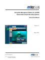
Diving Data Management Software for AxVIEW Subsea Video & Depth Recording Systems Instruction Manual Version 1.0 March 2015 Document ID: AxDDM_SW_IM_V1.0 AXSUB Inc. 112, Montee Industrielle, Suite 200 Rimouski (Québec) CANADA G5M 1B1 +1.418.731.1539 www.axsub.com ©AXSUB inc. 2011-2015 All rights reserved This manual and the information contained herein are provided for use as an operation and maintenance guide. No license or rights to manufacture, reproduce, or sell either the manual or articles described herein are given. AXSUB’s Quality Assurance System is certified by QUAZAR in accordance with ISO 9001:2008 in all of AXSUB Inc operations (Quality Certificate No. Q3749). AXSUB Inc. does not assume any responsibility for losses or claims by third parties, which may arise through the use of this device and accessories. Due to continuous product development, AXSUB Inc. reserves the right to change specifications without notice. This document applies to AxDDM Software Version 1.0 and to all subsequent releases. Specifications contained herein are subject to change and these changes will be reported in subsequent release notes or new editions. Copyright © 2015 AXSUB Inc. Rimouski, Quebec, Canada, and/or their licensors The name AxVIEW and all AXSUB product names are either trademarks or registered trademarks of AXSUB Inc. and/or their licensors. Other company and product names mentioned herein may be trademarks of their respective owners. Use of this software is subject to adherence to AXSUB’s licensing conditions and terms. These terms are part of the product documentation, located in the root installation directory of the licensed product(s). This software may include portions of third-party products. For third-party copyright notices and license terms, please refer to "License Texts, Copyright Notices and Disclaimers of Third Party Products." This document is part of the product documentation, located in the root installation directory of the licensed product(s). Document ID: AxDDM_SW_IM_V1.0 AXSUB Inc. 112, Montee Industrielle, Suite 200 Rimouski (Québec) CANADA G5M 1B1 +1.418.731.1539 www.axsub.com Page 3 of 37 ©AXSUB inc. 2011-2015 All rights reserved WARNING! READ THIS MANUAL CAREFULLY! Read this instruction manual in its entirety paying close attention to ALL WARNINGS listed below. Make sure that you fully understand the use, displays and limitations of the digital video recorder and dive computer because any confusion resulting from neglecting to follow this instruction manual or from improper use of this device may cause a diver to commit errors that may lead to serious injury or death. WARNING! FOR PROFESSIONAL USE! AXSUB Dive Data Management (AxDDM) Software and LED Controller & Camera Viewer (AxVIEW) are intended for professional use only. Commercial or professional diving activities may expose the diver to depths and conditions that tend to increase the risk of decompression illness (DCI). Therefore, AXSUB strongly recommends that the diving supervisor use these devices in redundancy with their conventional method as a backup solution (dive profile & decompression module). WARNING! ONLY DIVERS TRAINED IN THE PROPER USE OF Surface Supplied DIVING EQUIPMENT SHOULD USE THE AxVIEW! No computer can replace the need for proper Supervisory and Diver training. Insufficient or improper training may cause divers to commit errors that may lead to serious injury or death. WARNING! THERE IS ALWAYS A RISK OF DECOMPRESSION ILLNESS (DCI) FOR ANY DIVE PROFILE EVEN IF YOU FOLLOW THE DIVE PLAN PRESCRIBED BY DIVE TABLES OR A DIVE COMPUTER. NO PROCEDURE, DIVE COMPUTER OR DIVE TABLE WILL PREVENT THE POSSIBILITY OF DCI! An individual’s physiological make up can vary from day to day. The AxDDM Software cannot account for these variations. You are strongly advised to remain well within the exposure limits provided by the instrument to minimize the risk of DCI. As an added measure of safety, you should consult a physician regarding your fitness before diving. WARNING! USE BACK-UP INSTRUMENTS! Make sure that you use back-up instrumentation including a Pneumo gauge, submersible pressure gauge, timer or watch, and have access to decompression tables whenever diving with the Dive Profile and Decompression modules with the AxDDM software. Document ID: AxDDM_SW_IM_V1.0 AXSUB Inc. 112, Montee Industrielle, Suite 200 Rimouski (Québec) CANADA G5M 1B1 +1.418.731.1539 www.axsub.com Page 4 of 37 ©AXSUB inc. 2011-2015 All rights reserved WARNING! PERFORM PRECHECKS! Always activate and conduct a functionality check of the device before diving in order to ensure the pressure sensor reads atmospheric pressure, that the display works adequately and that the sensor is secured to the diver’s harness. We recommend using one battery pack (Product No. 011001 – B05Ah-24VDC) per diver connected to the AxVIEW system to enable the UPS battery back-up of the system or one or high capacity battery pack (001003 – B15Ah-24VDC). This will prevent shut down of the underwater light, computer rebooting and/or video loss (if applicable) in case a Main Power Supply shut down or voltage drop. WARNING! Although the AxVIEW systems does not count down the NO-FLYING TIME, ALWAYS REFER TO YOUR COMPANY PROCEDURES AND METHODS or follow your diving table procedures. There can never be a flying after diving rule that is guaranteed to completely prevent decompression illness! WARNING! DO NOT DIVE AT ALTITUDES GREATER THAN 300m WITH THE AXVIEW UNLESS IT IS EQUIPPED WITH AN ALTITUDE DIVING TABLES, Diving at altitude without compensation of the Actual and Decompression Stages Depth can increase the risk of DCI. WARNING! ALWAYS REFER TO YOUR COMPANY PROCEDURES AND METHODS! The Diving Data Management (AxDDM) Software and the AxVIEW System are intend to be a working tool for the commercial diving supervisor to crosscheck information and log information that can be referred to later on. You must always maintain and keep the paper system & external stopwatch to control the dive in case of technical problems with the device and/or sensors. Document ID: AxDDM_SW_IM_V1.0 AXSUB Inc. 112, Montee Industrielle, Suite 200 Rimouski (Québec) CANADA G5M 1B1 +1.418.731.1539 www.axsub.com Page 5 of 37 ©AXSUB inc. 2011-2015 All rights reserved Table of Contents 1. Safety Precautions ........................................................................................................................... 8 1.1 Software Limitations ................................................................................................................ 8 2. Release Notes .................................................................................................................................. 8 3. Software Requirements ................................................................................................................... 9 4. Getting Started .............................................................................................................................. 11 5. Registering..................................................................................................................................... 13 6. Complete Overview ....................................................................................................................... 14 6.1 Video Tab ............................................................................................................................... 14 6.1.1 Video Preview ................................................................................................................ 14 6.1.2 Recording ....................................................................................................................... 14 6.1.3 Snapshot ........................................................................................................................ 15 6.1.4 On Screen Display ........................................................................................................... 15 6.1.5 Timers ............................................................................................................................ 15 6.1.6 Comments ...................................................................................................................... 16 6.1.7 Multi View ...................................................................................................................... 17 6.2 Dive Tab ................................................................................................................................. 20 6.2.1 Start New Dive ............................................................................................................... 20 6.2.2 Axis Properties ............................................................................................................... 20 6.2.3 Bottom Alarm ................................................................................................................. 21 6.2.4 Save Chart as Image ....................................................................................................... 21 6.2.5 Finish/Reset Dive ............................................................................................................ 21 6.3 Deco Tab ................................................................................................................................ 23 6.3.1 Decompression using tables ........................................................................................... 23 6.3.2 Decompression without table ......................................................................................... 24 6.3.3 Move to chamber ........................................................................................................... 25 6.4 Report Tab ............................................................................................................................. 26 6.4.1 Pre-Dive Page ................................................................................................................. 26 6.4.2 Generate Page................................................................................................................ 28 6.5 Options Tab............................................................................................................................ 29 6.5.1 Program Options Page .................................................................................................... 29 6.5.2 Video Options Page ........................................................................................................ 29 Document ID: AxDDM_SW_IM_V1.0 AXSUB Inc. 112, Montee Industrielle, Suite 200 Rimouski (Québec) CANADA G5M 1B1 +1.418.731.1539 www.axsub.com Page 6 of 37 ©AXSUB inc. 2011-2015 All rights reserved 6.5.3 Depth Meters Options Page ............................................................................................ 30 7. Step-by-Step Typical Dive............................................................................................................... 32 6 AXSUB Limited Warranty for AxVIEW and Accessories ................................................................... 33 7 6.1 Warranty Period..................................................................................................................... 33 6.2 Exclusions and Limitations ...................................................................................................... 34 6.3 Access to AXSUB warranty service .......................................................................................... 35 6.4 Other important notices ......................................................................................................... 35 6.5 Limitation of Liability .............................................................................................................. 35 Disposal of the Device.................................................................................................................... 36 Document ID: AxDDM_SW_IM_V1.0 AXSUB Inc. 112, Montee Industrielle, Suite 200 Rimouski (Québec) CANADA G5M 1B1 +1.418.731.1539 www.axsub.com Page 7 of 37 ©AXSUB inc. 2011-2015 All rights reserved 1. Safety Precautions Do not attempt to use the AXVIEW without reading this instruction manual in its entirety, including all the warnings. Make sure that you fully understand the use, displays and limitations of the instrument. If you have any questions about the manual or the dive computer, contact your AXSUB dealer before diving with the dive computer. Always remember that YOU ARE RESPONSIBLE FOR THE SAFETY OF YOUR DIVES! When used properly, the AxVIEW is an outstanding tool for assisting properly trained, certified divers in planning and executing commercial dives. It is NOT A SUBSTITUTE FOR CERTIFIED DIVING SUPERVISOR INSTRUCTION, including training in the principles of decompression. 1.1 Software Limitations While the software is based on current decompression research and technology, you must realize that the software cannot monitor the actual physiological functions of an individual diver. All decompression schedules currently known to the authors, including the U.S. Navy and DCIEM Tables, are based on theoretical mathematical models, which are intended to serve as a guide to reduce the probability of decompression illness. 2. Release Notes Version 1.0 (February 2015) Initial software release under the name AxWare Version 1.1.2 (March 10, 2015) Name changed to AxDDM Software Changed comments entry method and added timestamp to comments Added a second stopwatch per timer Added buttons to stop/reset decompressions schedule Added depth display in the Chamber pages of the Deco tab Improved French version of the software. Reports can now be produced in French Dive number is now carried from projects to projects Corrected a bug that prevented depth meters to properly restart after failure Corrected a bug that prevented some decompression schedule from working Corrected a bug that caused display problems in the Multi-View Menu Corrected a bug with the camera assign function that caused problem with the 3 and 4 divers systems Document ID: AxDDM_SW_IM_V1.0 AXSUB Inc. 112, Montee Industrielle, Suite 200 Rimouski (Québec) CANADA G5M 1B1 +1.418.731.1539 www.axsub.com Page 8 of 37 ©AXSUB inc. 2011-2015 All rights reserved 3. Software Requirements Supported Operating Systems (English and French versions): - Windows 8.1, 32-bit Windows 8.1, 64-bit Windows 8, 32-bit Windows 8, 64-bit Windows 7, 32-bit Windows 7, 64-bit * Make sure to use the appropriate AxDDM installer for your operating system (x32 or x64), otherwise it may lead to installation failure or drivers incompatibilities * Other operating systems might work but are not officially supported by AXSUB Software requirements: - Microsoft .NET Framework 4.0 (installed by default with Windows 8 and Windows 8.1, otherwise available on Microsoft website) Document ID: AxDDM_SW_IM_V1.0 AXSUB Inc. 112, Montee Industrielle, Suite 200 Rimouski (Québec) CANADA G5M 1B1 +1.418.731.1539 www.axsub.com Page 9 of 37 ©AXSUB inc. 2011-2015 All rights reserved Software Installation 1) IMPORTANT: Before installation, unplug any AxVIEW or other AXSUB device (USB cables) from your computer or it may lead to improper installation of the required drivers 2) If your operating system is 32 bit, run AxDDM_x32.exe. If it is 64 bits, run AxDDM_x64.exe. 3) Follow the steps on screen until installation is completed. Note that during installation, setups for Sensoray’s video drivers and FTDI CDM communication drivers will start automatically. You must install those components for the software to work properly. Once the installation of all drivers is completed, this window will be displayed: Before you click Finish, if you choose to launch AxDDM, first connect your AxVIEW(s) to your computer and wait for drivers to be recognised. Document ID: AxDDM_SW_IM_V1.0 AXSUB Inc. 112, Montee Industrielle, Suite 200 Rimouski (Québec) CANADA G5M 1B1 +1.418.731.1539 www.axsub.com Page 10 of 37 ©AXSUB inc. 2011-2015 All rights reserved 4. Getting Started 1) Project Selection Every time the AxDDM Software is launched, the Project Selection window will appear. This window allows the user to choose the location where all files produced by the software (videos, snapshots, reports, etc.) will be saved for the current project. By default, the main folder for projects is the Documents\AxDDM folder. You can choose to either create a new project: Or you can choose to load an existing project: Document ID: AxDDM_SW_IM_V1.0 AXSUB Inc. 112, Montee Industrielle, Suite 200 Rimouski (Québec) CANADA G5M 1B1 +1.418.731.1539 www.axsub.com Page 11 of 37 ©AXSUB inc. 2011-2015 All rights reserved 2) Once a new project has been created, or an old project loaded, the main software window will appear: Until the software is registered, only the Video tab and the Options tab are available. The Video tab allows the user to record videos, take snapshots, display text on screen and use basic timer functions like stopwatches and countdowns. Note that while a camera is displayed in the main panel, all other cameras are still being displayed in the Inactive Video Streams column on the left side. If the MultiView tab is selected, multiple video streams may be displayed in the main panel at the same time with the desired configuration. When all available cameras are displayed in the main panel, the Inactive Video Streams column automatically hides. The Options tab allows user to configure the program options, the videos options and if registered, the depth meters options. Document ID: AxDDM_SW_IM_V1.0 AXSUB Inc. 112, Montee Industrielle, Suite 200 Rimouski (Québec) CANADA G5M 1B1 +1.418.731.1539 www.axsub.com Page 12 of 37 ©AXSUB inc. 2011-2015 All rights reserved 5. Registering To unlock the software and access the Dive, Decompression and Report menus, the software must registered. To do so, an appropriate license key must be entered in the License Key textbox in the Program Options page. The license key is linked to the video encoders’ serial number. Therefore, each license only work with a specific AxVIEW system. Once unlocked, the software will ask to configure depth meters. If chosen not to do so, it is still possible to do it later in the Depth Meters Options page. Finally, after depth meters configuration, the license status will change and the Report, Dive and Deco tabs will be available, as well as the Depth Meters Options page. Document ID: AxDDM_SW_IM_V1.0 AXSUB Inc. 112, Montee Industrielle, Suite 200 Rimouski (Québec) CANADA G5M 1B1 +1.418.731.1539 www.axsub.com Page 13 of 37 ©AXSUB inc. 2011-2015 All rights reserved 6. Complete Overview 6.1 Video Tab 6.1.1 Video Preview The video preview for each camera can be seen in the corresponding Diver page of the Video tab. The previews are designed to always keep their height to width ratio. This way, the main window can be resized at any time without losing the video’s proportions. The video preview will always adapt itself to best fit the screen, thus if the width limits the size, the video will take all width and fill empty space with black borders, and if the height limits the size, the video will take all height and fill empty space with black borders 6.1.2 Recording To record a video, click on the REC button. The button will turn red to indicate that the camera is recording. To stop recording, click again on the REC button. A window will appear to confirm the end of recording. The length of all video files can be set in the Video Options tab with a minimum length of 1 minute and a maximum length of 360 minutes (6 hours). When the length of a recording video exceeds the set point, the recorded files is automatically saved and a new file is created to keep recording. This options is used to facilitate post-processing of video files and to minimise risks of data loss due to file corruption. The quality of all video files can also be set in the Video Options tab. The available options are Low (2 500 Kbit/s), Medium (5 000 Kbit/s) and High (10 000 Kbit/s). Document ID: AxDDM_SW_IM_V1.0 AXSUB Inc. 112, Montee Industrielle, Suite 200 Rimouski (Québec) CANADA G5M 1B1 +1.418.731.1539 www.axsub.com Page 14 of 37 ©AXSUB inc. 2011-2015 All rights reserved All video files are saved in the Videos folder of the current project folder (default: MyDocuments\AxDDM\ MyProject \Videos), with the name of each file being the timestamp of the start of the recording plus the diver number. 6.1.3 Snapshot To take a picture of what is currently shown by the camera, click the Snapshot button. A preview window will appear on screen to show the taken picture for a definite amount of seconds and will then close automatically. The display time can be set in the Video Options tab. All image files are saved in the Images folder of the current project folder (default: MyDocuments\AxDDM\ MyProject \Images), with the name of each file being the timestamp of the snapshot plus the diver number. 6.1.4 On Screen Display The OSD (on screen display) buttons are used to add text on the top left corner of the video. There are 3 pre-set OSD texts that can be added, which are the date and time, the diver number and the current depth with units. When clicked, their buttons will turn red to indicate their new status. There is a fourth OSD button that allows user to add custom text. When clicked, this button will open a window with a textbox to write the custom text. To write multiple lines of text, simply add the characters ^n. Example: The text: PillarABC^nBridgeXYZ Will display: PillarABC BridgeXYZ The Enter key can also be pressed to add another line, but unwanted characters may appear at the end of the line. The maximum number of characters that the OSD can display is 80. Excess characters will be ignored. 6.1.5 Timers The Video tab contains basic timer tools to help supervisors during dive. The button Show of the Timer box will open a window containing 2 stopwatches and 1 countdown timer. The stopwatches are named Total and Event, but can be used to measure the time of any event. When the Start button is clicked, the text will change to Stop and it will turn red to indicate that it is running and the time display will start to show elapsed time. If the Stop button is clicked, it will pause the timer, which can be restarted from its current state at any time by pressing Start again. The Reset button can be clicked at any time to bring the elapsed time back to 00:00:00. Note that the stopwatch timers are based on the computer’s date and time settings, thus it is not recommended to change the computer’s time during measurement or it will affect the stopwatches elapsed time. To set the countdown timer, click in the time textbox and enter the desired time value with your keyboard. Once done, click on the Set button to save the value and enable the Start button. When the Document ID: AxDDM_SW_IM_V1.0 AXSUB Inc. 112, Montee Industrielle, Suite 200 Rimouski (Québec) CANADA G5M 1B1 +1.418.731.1539 www.axsub.com Page 15 of 37 ©AXSUB inc. 2011-2015 All rights reserved Start button is clicked, the text will change to Stop and it will turn red to indicate that it is running and the time display will start to show remaining time. If the Stop button is clicked, it will pause the timer, which can be restarted from its current state at any time by pressing Start again. The Reset button can be clicked when the timer is stopped to enter a new countdown value. The countdown timers are all linked to an alarm that will automatically start when the remaining time is less than 10 seconds. When the alarm is triggered, the Video tab will start flashing yellow and red, as well as the Diver tab for which the timer is set and the Show button of the Timer box. This way, if the timer window isn't showed on screen, the user will know exactly where to go to stop the alarm. Click on the Stop button to shut the alarm. The timer windows are designed to always be displayed on top of any other page, so that the supervisor can always keep an eye on them if needed. They can be closed by clicking the X in the top right corner, and the timers will keep working in the background even if not showed. 6.1.6 Comments The Comments textbox is used to print comments on the report. To add a comment, write text in the Comments textbox and click on the Add Comment button. A timestamp will automatically be added to the comment. At any time, you can view and modify all comments by clicking the Show Comments button. This will open a window containing all text to be printed on the report. You can add or modify the text as you wish, and click Apply to save your modifications or Cancel, to restore the text to what it was before you click the Show Comments button. Document ID: AxDDM_SW_IM_V1.0 AXSUB Inc. 112, Montee Industrielle, Suite 200 Rimouski (Québec) CANADA G5M 1B1 +1.418.731.1539 www.axsub.com Page 16 of 37 ©AXSUB inc. 2011-2015 All rights reserved 6.1.7 Multi View 2 divers system To display both video streams in the main panel, simply select the MultiView page of the Video tab and choose one of the four possible configurations by clicking the corresponding button. 3 or 4 divers system When a 3 or 4 divers system is connected to the computer, the MultiView page is different than with 2 divers system. There are 3 buttons for favorite configurations and a button to open the MultiView Menu. When the software is run for the first time, the favorite configuration buttons are blank, because they need to be set in the MultiView Menu. Once set, they will take the shape of their corresponding configuration. Document ID: AxDDM_SW_IM_V1.0 AXSUB Inc. 112, Montee Industrielle, Suite 200 Rimouski (Québec) CANADA G5M 1B1 +1.418.731.1539 www.axsub.com Page 17 of 37 ©AXSUB inc. 2011-2015 All rights reserved Click on the Open MultiView Menu button to open the MultiView Menu. Document ID: AxDDM_SW_IM_V1.0 AXSUB Inc. 112, Montee Industrielle, Suite 200 Rimouski (Québec) CANADA G5M 1B1 +1.418.731.1539 www.axsub.com Page 18 of 37 ©AXSUB inc. 2011-2015 All rights reserved This menu shows all the possible configurations to display videos in the MultiView page. If a 3 divers system is connected to the computer, all the 4 cameras configurations won’t be shown. To select a configuration, click on it to be automatically redirected to the main window with the selected configuration. To set Favorite buttons, click on a Select button, then click on any configuration button to assign the configuration to the selected Favorite button. Document ID: AxDDM_SW_IM_V1.0 AXSUB Inc. 112, Montee Industrielle, Suite 200 Rimouski (Québec) CANADA G5M 1B1 +1.418.731.1539 www.axsub.com Page 19 of 37 ©AXSUB inc. 2011-2015 All rights reserved 6.2 Dive Tab 6.2.1 Start New Dive Before starting a new dive, depth meters must be configured. See section 7.5.3 to see how to configure depth meters. To start logging depth, click on the Start Dive button. Once clicked, the text will change to Finish Dive and it will turn red to indicate that the depth is logging. The Dive Time timer and the Bottom Time timer will also start when the Start Dive button is clicked. Note that the timers are based on the computer’s date and time settings, thus it is not recommended to change the computer’s time during measurement or it will affect the Dive Time and the Bottom Time. Starting a new dive will also make the Arrived Bottom button appear in the Alarm box. Even though no bottom alarm is set, the Arrived Bottom button may clicked. By clicking on this button, the time at which the diver arrived at the bottom will be printed on the report. 6.2.2 Axis Properties By default, the chart’s axis are auto-scaled to best fit the depth curve. It is however possible to use custom axis values on the depth chart. Click on the ShowAxisProperties checkbox to display the axis settings. To set the Y axis limit values, write the desired values in the Min Depth and Max Depth textboxes, or select the values by clicking on the up and down arrows of the textboxes. For the X axis, the same applies but with the Min Time and Max Time textboxes. At any time, you can return to auto-scaled axis Document ID: AxDDM_SW_IM_V1.0 AXSUB Inc. 112, Montee Industrielle, Suite 200 Rimouski (Québec) CANADA G5M 1B1 +1.418.731.1539 www.axsub.com Page 20 of 37 ©AXSUB inc. 2011-2015 All rights reserved by clicking the Autoscale button. Also, X and Y axis are independents. This implies that if custom axis values are set for the Y axis, the X axis values will remain auto-scaled until configured, and vice-versa. 6.2.3 Bottom Alarm The target bottom alarm is a tool made available to the supervisor to remember to click on the Arrived Bottom button when the diver reaches the bottom, thereby printing the time for this event on the report. To set the target bottom, write the target value in the textbox then click on the Set Alarm button. The button will turn red to indicate that the alarm is set. When the alarm is triggered, the Dive tab will start flashing yellow and red, as well as the Diver page for which the alarm is set. This way, the user will know exactly where to go to stop the alarm. Click on the Arrived Bottom button to shut the alarm. 6.2.4 Save Chart as Image At any time, the depth chart can be saved as a JPEG file containing the chart with its current axis values by clicking on the Save as Image button. The file will be saved in the Images folder of the current project folder (default: MyDocuments\AxDDM\ MyProject \Images), with the name of each file being the timestamp plus the chart number. 6.2.5 Finish/Reset Dive Clicking the Finish Dive button means that the diver is back to surface. When clicked, this button will stop depth logging, stop the Dive Time timer and will enable the option to move decompression to a chamber. A question box will appear to confirm the end of dive, as once stopped it is not possible to restart the depth logging and the Dive Time timer from their current state. A new dive has to be started to re-use these features. Document ID: AxDDM_SW_IM_V1.0 AXSUB Inc. 112, Montee Industrielle, Suite 200 Rimouski (Québec) CANADA G5M 1B1 +1.418.731.1539 www.axsub.com Page 21 of 37 ©AXSUB inc. 2011-2015 All rights reserved If the Start Final Ascent button of the Deco tab is clicked, a built-in alarm will automatically be set to trigger when the diver reaches less than 5 feet of the surface. When the alarm is triggered, the Dive tab will start flashing yellow and red, as well as the Diver page for which the timer is set and the Finish Dive button. This way, the user will know exactly where to go to stop the alarm. Click on the Finish Dive button to shut the alarm. If for whatever reasons the diver has to go down again under the 5 feet trigger mark before the dive is stopped, the alarm will stop temporarily while the diver is under 5 feet, and start again when he gets back above the trigger mark. When in the 0-5 feet alarm zone, if not stopped, the alarm can be muted by clicking the Mute Alarm button. The alarm will still be active and the visual indicators will flash, but the sound will be muted. The Mute Alarm button will turn red when clicked to indicate the alarm is muted. When the Finish Dive button is clicked, the Reset button will become enabled. When clicked, this button will reset the depth chart, the Dive Time and Bottom Time timers, the decompression table and the various alarms relative to the dive. IMPORTANT: reports must be generate prior to reset the dive, otherwise all information about the dive will be lost. If the decompression is to be moved to chamber to free up the equipment for another diver, it must also be done prior to reset the dive. Document ID: AxDDM_SW_IM_V1.0 AXSUB Inc. 112, Montee Industrielle, Suite 200 Rimouski (Québec) CANADA G5M 1B1 +1.418.731.1539 www.axsub.com Page 22 of 37 ©AXSUB inc. 2011-2015 All rights reserved 6.3 Deco Tab 6.3.1 Decompression using tables Decompression is a function of both the bottom time and the max depth. Actual values of these variables are stored in the Deco Values box of the Deco tab. When a decompression table is selected in the Table combo box, the Show Steps button will use these values to determine the decompression schedule and show the steps in the spreadsheet. Any value between two decompression schedules will result in the next schedule being selected. It is also possible to use custom values to determine the decompression schedule. This may be used, for example, to set a security factor over the bottom time and max depth values. To set the custom values, write the desired value in the corresponding textbox and click on the Set button. It will turn red to indicate that the custom value is selected and the Deco Values will also be updated. Click on the Set button again to return to the actual values rather than the custom values. To use tables in meters, select the tables ending with “m”, by example “tb_DCIEM_1m”. All other tables, or if unspecified, are in feet. Every time some modifications are made with the custom values, or actual values, click on the Show Steps button to update the spreadsheet with the correct decompression schedule. Because clicking the Start Final Ascent button to start a decompression will automatically update the spreadsheet to fit the Deco Values, it is recommended to click the Show Steps immediately before starting the decompression to make sure all steps are correct. Once the table is selected and the shown steps have been revised according to your company procedures and approved by a qualified supervisor, click the Start Final Ascent button to start the decompression profile. As stated in section 7.2.5, the Start Final Ascent button will enable the finish dive alarm. See section 7.2.5 for details. Once decompression is started, elapsed time timers will automatically start. The time at which a step is reached or quit will also automatically be added in the spreadsheet. To go to the next step, click on the Next Step button. When no more steps are required, click on the Stop Deco button. A built-in alarm is set to trigger when the remaining time of a step is less than 10 seconds. When the alarm is triggered, the Deco tab will start flashing yellow and red, as well as the Diver page for which the timer is set and the Next Step button. This way, the user will know exactly where to go to stop the alarm. The alarm can be muted by clicking the Mute Alarm button. The alarm will still be active and the visual indicators will flash, but the sound will be muted. The Mute Alarm button will turn red when clicked to indicate the alarm is muted. At any time, decompression can be reset by clicking on the Restart Deco button. Document ID: AxDDM_SW_IM_V1.0 AXSUB Inc. 112, Montee Industrielle, Suite 200 Rimouski (Québec) CANADA G5M 1B1 +1.418.731.1539 www.axsub.com Page 23 of 37 ©AXSUB inc. 2011-2015 All rights reserved 6.3.2 Decompression without table If no decompression table is selected prior to click on the Start Final Ascent button, step timers will still be available to log the elapsed step time. There won’t be any step name or reference time, but times at which the steps are reached or quitted will be logged. Thus, when printing the decompression spreadsheet on the report, it is possible to fill the missing cells by hand. As with decompression using tables, click on the Next Step button to go to the next step, and click on the Stop Deco button when decompression is complete. Document ID: AxDDM_SW_IM_V1.0 AXSUB Inc. 112, Montee Industrielle, Suite 200 Rimouski (Québec) CANADA G5M 1B1 +1.418.731.1539 www.axsub.com Page 24 of 37 ©AXSUB inc. 2011-2015 All rights reserved 6.3.3 Move to chamber When the Finish Dive button of the Dive tab is clicked, the Move to Chamber button will appear in the corresponding Deco tab page. This button transfers all dive data to be printed on report to a new chamber tab. This include all comments wrote in the Video tab prior to the switch to chamber. The Chamber tab allows decompression schedule to be continued even though the diver is not in water anymore. All equipment (camera, light, depth meters, etc.) used by the diver is thereby free to use by another diver and the depth chart can be reset without losing data. Moving to the next step in the Chamber page works the same way as in the Deco page, and if decompression with table is used, alarms will also trigger when the remaining step time is less than 10 seconds. If a chamber depth meter is configured, the depth will be displayed in the Actual Depth textbox. To generate the report of a dive profile that has been moved to chamber, use the Generate Report button of the Chamber page. Document ID: AxDDM_SW_IM_V1.0 AXSUB Inc. 112, Montee Industrielle, Suite 200 Rimouski (Québec) CANADA G5M 1B1 +1.418.731.1539 www.axsub.com Page 25 of 37 ©AXSUB inc. 2011-2015 All rights reserved 6.4 Report Tab 6.4.1 Pre-Dive Page The Pre-Dive page is used to write most of the information to be printed on the dive report. By default, the Default Pre-Dive sheet is selected, and this sheet is used to produce the generic AXSUB report. To update the pre-dive sheet, click the Change PreDive button. The sheet will turn brown to indicate its being modified. The Project box of the sheet is to set the dive number, the vessel name and the location. Dive number will automatically increment by 1 every time a new report is generated, allowing to keep track of the reports with the software. The number can however be set manually by clicking the Set button. The Client box is to set all contact information about the client. To add or delete a client profile, click the Manage Client Profiles button. A window will open containing the current profiles list and options to add/delete profiles. To delete a profile, select it in the list and click the Delete Profile button. To add a profile, click the Add New Profile button, and fill the textboxes in the Client Profile box. When creating a new profile, profile name can’t be blank or be the same as an already existing profile. Once the textboxes are filled, click the Add Profile button to add the profile to the list, or click Cancel to stop editing a new profile. Once profile list is completed, click the Save button to update the list in the PreDive page, or click Cancel to dismiss the changes. Document ID: AxDDM_SW_IM_V1.0 AXSUB Inc. 112, Montee Industrielle, Suite 200 Rimouski (Québec) CANADA G5M 1B1 +1.418.731.1539 www.axsub.com Page 26 of 37 ©AXSUB inc. 2011-2015 All rights reserved The Dive-Team box is to set the roles of each member and to note the air banks and the bail-out bottles pressures. To add or delete a team member, click the Manage Members button. A window will open containing the current members and options to add/delete members. To delete a member, select it in the list and click the Delete button. To add a member, write his name in the textbox and click the Add button. Once member list is completed, click the Save button to update the list in the PreDive page, or click Cancel to dismiss the changes. Once all changes have been made to the pre-dive sheet, click the Save Project button to apply changes. The Cancel button can also be clicked to stop editing pre-dive and dismiss changes. Also, leaving the predive page while edition is ongoing will result in all changes being dismissed. The Reset PreDive button is used to empty all boxes of the pre-dive sheet except for the dive number textbox. All client profiles and team members will remain but they will have to be selected from their corresponding textboxes. Companies that want to use a specific report template may contact AXSUB to talk about integrating their report to the software. When bought, these customs report pages will be made available through a specific license key. All information about the pre-dive page is saved in the project folder (default: MyDocuments\AxDDM\ MyProject). When creating a new project, client profiles and team members will available but they will have to be selected from their corresponding textboxes. The dive number is set to carry from one project to another. Document ID: AxDDM_SW_IM_V1.0 AXSUB Inc. 112, Montee Industrielle, Suite 200 Rimouski (Québec) CANADA G5M 1B1 +1.418.731.1539 www.axsub.com Page 27 of 37 ©AXSUB inc. 2011-2015 All rights reserved 6.4.2 Generate Page The Generate page is used to write information about the dive-team’s company, to select the logo to be printed on the report and to produce the report itself. To select the logo, click on the Select button and choose a JPEG file from your computer. Once selected, the logo will appear in the Logo Preview box. Logos will be automatically resized to fit the available space while keeping their size ratio, but logos that are more than 3 times wider than tall might not be resized appropriately. To produce the report, click the Generate Report button for the corresponding diver. A report containing information for all divers can also be produced. All reports made with the generic template contains the pre-dive information, the dive data, the depth chart, the decompression spreadsheet and the video comments. All reports are saved as PDF files in the report folder (default: MyDocuments\AxDDM\ MyProject\Reports) with the name of each file being the timestamp plus the diver number. Document ID: AxDDM_SW_IM_V1.0 AXSUB Inc. 112, Montee Industrielle, Suite 200 Rimouski (Québec) CANADA G5M 1B1 +1.418.731.1539 www.axsub.com Page 28 of 37 ©AXSUB inc. 2011-2015 All rights reserved 6.5 Options Tab 6.5.1 Program Options Page The Program Options page is used to unlock the AxDDM software with an appropriate license key, to view the error log and to change the language of the software. As of version 1.1.1, supported languages are English and French. When the Error Log button is clicked, a window will appear containing all failure events and their timestamp since the program start up. The possible failure are: Connection lost between camera X and the AXSUB device Connection lost between video encoder X in the AXSUB device and the computer Recording stopped on camera X to help prevent file corruption Recording restarted on camera X Connection lost between depth meter X and the AXSUB device Connection lost between depth meters of COM port X and computer The Program Options page also displays the technical information such as the software version, the firmware version and the encoders’ serial numbers. For license configuration, see section 6. 6.5.2 Video Options Page The Video Options page is used to set various parameters relative to the cameras and the video encoders. The Camera Type box is used to set the camera type. Cameras can be either NTSC or PAL, but all cameras must be the same type. NTSC cameras can’t run alongside PAL cameras, and vice-versa. The Video Recording box is used to set the quality of the recordings and length of the video files. See section 7.1.2 for further details about recording. The Levels box is used to set video’s brightness, contrast, saturation and hue. All levels can be set using the slide bars and can be set back to default values by clicking the Defaults button. The Video Color box is a sub function of the Levels box that applies minimum saturation in order to get a black and white image. All changes made to levels affect both the video preview and the video recording. The Audio Preview box is used to start or stop the audio previews. The audio preview is a preview of what sound is being recorded by the video encoders. When started, the preview will be read by the computer and should be played if it has speakers. In most AxVIEW, the Audio In is shared by all encoders, thus it is not necessary to start all audio previews of an AxVIEW to hear what is recorded by all encoders. Starting all previews of encoders sharing the same audio input will result in sound superposition. Document ID: AxDDM_SW_IM_V1.0 AXSUB Inc. 112, Montee Industrielle, Suite 200 Rimouski (Québec) CANADA G5M 1B1 +1.418.731.1539 www.axsub.com Page 29 of 37 ©AXSUB inc. 2011-2015 All rights reserved The Snapshot Preview box is used to set the display time of the snapshot preview. The maximum display time is 120 seconds (2 minutes) and the minimum display time is 1 second. See section 7.1.3 for further details about snapshots. The Failure Options box is used to set the automatic recording restart after failure. If deactivated, user will have to manually restart any recording that was stopped due to a signal loss between a camera and an AxVIEW or an encoder and the computer. The Inactive Streams box is used to display the Inactive Video Streams column. The Display button will turn red if active. The Camera Assign box is used to assign cameras to divers. To change the default configuration, select a camera in the list, then click the up and down arrows to change its position. Once the new order is set, click the Apply button to assign each camera to its diver. Note that while any video is being recorded, the Camera Type box, the Quality box of the Video Recording box and the Camera Assign box are all disabled. Stop all recording to enable these features again. 6.5.3 Depth Meters Options Page The Depth Meter Options page is used to set various parameters relative to the depth meters. The Active Devices let the user choose which sensors are enabled and set their communication addresses. To enable a sensor, click on its corresponding button. It will turn red to indicate it is enabled. To communicate with a depth meter, its address must be entered in the corresponding textbox. The communication address is the last 2 digits of the serial numbers of the AxSEE 57i or the AxDEPTH 57S. For instance, the address for serial number 005-0125 is 25, and for serial number 005-0205, the address is 5. The exception is for serial numbers terminating with 00 (as 005-0200): in such case, use address 1 instead of 0. It is important to define a unique address for all divers connected - cannot use a camera 005-0225 (address 25) with camera 005-0125 (address 25). Same for camera 005-0200 (address 1) with camera 005-0101 (address 1). The COM Ports box is used to set the communication between the depth meters and the computer. The Auto-Configure Ports button will automatically search all available COM ports of a computer and open the ports associated with any enabled sensors from the Active Devices box. Ports can also be opened and closed manually by selecting them in the Ports Names combo boxes and then clicking the Open Port and Close Port buttons. A maximum of 4 ports can be opened by the AxDDM software, and once opened, they will lock their corresponding combo boxes and display a grey dot in the COM Active radio buttons. The Refresh Ports button is used to update the port list in the combo boxes with the names of the remaining available COM ports of the computer. When a COM port is opened, if it is able to communicate with any enabled sensor it will change to color of the Enabled Sensors button of the Active Devices box to green, to indicate that the sensor is not only enabled, but also communicating. Document ID: AxDDM_SW_IM_V1.0 AXSUB Inc. 112, Montee Industrielle, Suite 200 Rimouski (Québec) CANADA G5M 1B1 +1.418.731.1539 www.axsub.com Page 30 of 37 ©AXSUB inc. 2011-2015 All rights reserved The Units box is used to select whether the depth is expressed in Feet of Sea Water or in Meters of Sea Water and if the temperature is expressed in degrees Celsius or in degrees Fahrenheit. The Sensor Information box shows the actual pressure and temperature values read by the depth meters. The Custom Zero box is a tool to help recover from a failure. Depth is measured by a difference of pressure between surface and distance underwater. Depth measures therefor need a surface pressure reference in order to measure depth. Every time a COM port is opened, all sensors on this particular COM port are initialised and the surface pressure references are taken, unless the depth charts associated with these sensors have been started. This way, if COM port communication is briefly lost in the middle of a dive, surface pressure reference won’t be erased and replaced by new values when communication is renewed. But if for any reason the surface pressure references are lost (computer failure, software failure, accidental program closing, etc.) some custom references may be used. This way, when software is restarted and surface pressure references are actually taken underwater, it is possible to bypass to wrong references with custom ones. To use custom values, write the value in the corresponding textbox and click on the Set button. It will turn red to indicate custom zero is being used. To separate digits, use a comma with a French operating system and a dot with an English operating system. Any incorrect entry will lead to the Set button going back to default state and custom value being ignored. Document ID: AxDDM_SW_IM_V1.0 AXSUB Inc. 112, Montee Industrielle, Suite 200 Rimouski (Québec) CANADA G5M 1B1 +1.418.731.1539 www.axsub.com Page 31 of 37 ©AXSUB inc. 2011-2015 All rights reserved 7. Step-by-Step Typical Dive This is a step-by-step guide for a typical dive, assuming drivers have been installed and software has been unlocked with a proper license key. 1. 2. 3. 4. 5. 6. 7. 8. 9. 10. 11. 12. 13. 14. 15. 16. 17. 18. 19. 20. 21. 22. 23. 24. 25. 26. 27. 28. Connect all cameras, lights and cables to the AxVIEW and turn the power on. Connect the USB cable from the AxVIEW to the computer, and wait for drivers to be recognised Launch AxDDM Software Enter a project name in the Create New textbox and click on the Create button When ask to configure Depth meters, click Yes Click on all sensors to turn them active (red) and write their addresses in the textboxes Click on Set and wait for software to finish loading In the Pre-Dive page of the Report tab, click the Change PreDive button Fill the PreDive sheet and click the Save Project button Select the Generate page of the Report tab, fill the company information and select the company logo Select the Video Options page of the Options tab Choose the camera type, the recording quality, the files length, the snapshot preview time and assign the cameras to different divers if needed Select the Depth Meter Options page of the Options tab Choose the depth and temperature units Select the Dive tab and set the Target Bottom Alarms When ready to dive, click the Start Dive button Select the Video tab, choose the OSD settings and click the REC button to start recording At any point during dive, write comments using the textboxes of the Video tab and take snapshots with the Snapshot button When bottom alarm is triggered, click the Arrived Bottom button When ready for ascent, select the Deco tab Choose a decompression table If needed, add a security factor to actual values by using custom values Click Show Steps and validate all steps are accurate Click Show Steps again, make sure nothing has changed since validation and click the Start Final Ascent button Whenever a step is completed, click the Next Step button When surface is reached after all in-water steps, click Finish Dive in the Dive tab to turn the surface alarm off Select the Video tab and click the REC button to stop recording Select the Deco tab Document ID: AxDDM_SW_IM_V1.0 AXSUB Inc. 112, Montee Industrielle, Suite 200 Rimouski (Québec) CANADA G5M 1B1 +1.418.731.1539 www.axsub.com Page 32 of 37 ©AXSUB inc. 2011-2015 All rights reserved No chamber decompression 29. 30. 31. 32. Click the Stop Deco button Go to the Generate page of the Report tab and click the Generate Report button. Select the Dive tab and click the Reset button Equipment is now available for a new diver No chamber decompression 28. 33. 34. 35. Click the Move to Chamber button In the Chamber page of the deco Tab, click the Next Step button whenever a step is completed While decompression in chamber, equipment is free to use by another diver When all steps are completed, click the Stop Deco button, then the Generate Report button of the Chamber page 6 AXSUB Limited Warranty for AxVIEW and Accessories This Limited Warranty is valid as of August 1st, 2012. AXSUB Inc. (“AXSUB”) provides this limited warranty to those who have purchased the AxVIEW and/or AXSUB diving accessories (“Product”). AXSUB warrants that during the Warranty Period AXSUB or an AXSUB Authorized Service Center will, at its sole discretion, remedy defects in materials or workmanship free of charge either by a) repairing the Product or the parts, or b) replacing the Product or the parts, or c) refunding the purchase price of the Product, subject to the terms and conditions of this Limited Warranty. Your mandatory legal rights under your applicable national laws relating to the sale of consumer products are not affected by this Limited Warranty. This Limited Warranty is only valid and enforceable in the country in which you purchased the Product, provided that AXSUB has intended the Product for sale in that country. If, however, you purchased the Product in a member state of the European Union, Iceland, Norway, Switzerland or Turkey, and AXSUB originally intended the Product for sale in one of these countries, this Limited Warranty is valid and enforceable in all of these countries. The warranty service may be limited due to the possible countryspecific elements in the Products. Any service made during and after warranty subject to service fee and compensation for the shipment costs incurred by AXSUB or an AXSUB Authorized Service Centre. You can have warranty service other than in the country in which you purchased the Product. 6.1 Warranty Period The Warranty Period starts at the date of retail purchase by the original end-user purchaser. The Product may consist of several different parts, and the different parts may be covered by a different warranty period (hereinafter “Warranty Period”). The different Warranty Periods are: 1) One (1) year for the AxVIEW systems Document ID: AxDDM_SW_IM_V1.0 AXSUB Inc. 112, Montee Industrielle, Suite 200 Rimouski (Québec) CANADA G5M 1B1 +1.418.731.1539 www.axsub.com Page 33 of 37 ©AXSUB inc. 2011-2015 All rights reserved 2) Three (3) months for the consumable parts and accessories, including (but not limited to) chargeable batteries, chargers, cameras, lamps, depth meters, cables, power supply (whether included in the AxVIEW sales package or sold separately). To the extent your national laws permit, the Warranty Period will not be extended or renewed or otherwise affected due to subsequent resale, AXSUB authorized repair or replacement of the Product. However, part(s) repaired or replaced during the Warranty Period will be warranted for the remainder of the original Warranty Period or for three (3) months from the date of repair or replacement, whichever is longer. 6.2 Exclusions and Limitations This Limited Warranty does not cover: 1) a) normal wear and tear, b) defects caused by rough handling (including, without limitation, defects caused by sharp items, by bending, compressing or dropping, etc.), or c) defects or damage caused by misuse of the Product, including use that is contrary to the instructions provided by AXSUB (e.g. as set out in the Product’s user guide and/instruction manual), and/or e) other acts beyond the reasonable control of AXSUB; 2) User manuals or any third-party software (even if packed or sold with the AXSUB hardware), settings, content or data, whether included or downloaded in the Product, or whether included during installment, assembly, shipping or at any other time in the delivery chain or otherwise and in any way acquired by you; 3) Defects or alleged defects caused by the fact that the Product was used with, or connected to, any product, accessory, software and/or service not manufactured or supplied by AXSUB, or was used otherwise than for its intended use; 4) Usage with a power supply other than AXSUB product PS-24V-001; 5) Usage with a battery different than an AXSUB Battery Pack B05Ah-24VDC or B15Ah-24VDC; 6) Usage with a power source different outside limits of the power supply: 100-240VAC 50/60Hz. This Limited Warranty is not enforceable if: 1) The Product has been opened, modified or repaired by anyone other than AXSUB or a AXSUB Authorized Service Centre; 2) The Product has been repaired using unauthorized spare parts; 3) The Product’s serial number has been removed, erased, defaced, altered or made illegible in any way - and this shall be determined at the sole discretion of AXSUB; 4) The Product has been used when surrounding temperature exceed the limits of -20…50°C; 5) The Product has been exposed to influence from chemical products including (but not limited to) mosquito repellents; 6) The Product has been used in a dust / particle contaminated air that might block ventilation orifices; 7) The Product has been cleaned with a high pressure air jet. Document ID: AxDDM_SW_IM_V1.0 AXSUB Inc. 112, Montee Industrielle, Suite 200 Rimouski (Québec) CANADA G5M 1B1 +1.418.731.1539 www.axsub.com Page 34 of 37 ©AXSUB inc. 2011-2015 All rights reserved AXSUB does not warrant that the operation of the Product will be uninterrupted or error free or that the Product will work in combination with any hardware or software provide by a third party. 6.3 Access to AXSUB warranty service Please access and review the online help resources available at www.axsub.com/FAQ or referred to in the Product manual before seeking warranty service. If a claim under this Limited Warranty appears to be necessary, please contact your local authorized AXSUB retailer – for contact information please visit the AXSUB website www.axsub.com or call the AXSUB Help Desk (national or premium rates may apply) for further details on how to make a claim. You will then be advised on how to bring your Product for warranty service. Should you wish to return the Product by shipping it to your local authorized AXSUB retailer, please use prepaid freight. When making a claim under this Limited Warranty you are required to include your name and address, proof of purchase and/or service registration card (AXSUB warranty registration at www.axsub.com is considered adequate for this purpose), as required in your country, which clearly indicates the serial number, name and address of the seller, the date and place of purchase, and the product type. The claim will be honored and the Product repaired or replaced at no charge and returned in a reasonable amount of time. This shall be determined at the sole discretion of AXSUB or an AXSUB Authorized Service Center. If the Product is found not to be covered by the terms and conditions of this Limited Warranty, AXSUB or an AXSUB Authorized Service Centre reserve the right to charge a handling fee. Any claim under this Limited Warranty is subject to you notifying AXSUB or a AXSUB Authorized Service center of the alleged defect within a reasonable time of it having come to your attention, and in any event no later than before the expiry of the Warranty Period. 6.4 Other important notices Please remember to take backup copies of all important content and data stored in your Product (if applicable) because content and data may be lost during repair or replacement of the Product. AXSUB or a AXSUB Authorized Service Centre is not responsible for any damage or loss of any kind whatsoever resulting from loss of, damage to, or corruption of content or data during repair or replacement of the Product. When the Product or a part is replaced, any replaced item becomes the property of AXSUB. If a refund is given, the Product for which the refund is given must be returned to an AXSUB Authorized Service Centre as it becomes the property of AXSUB and/or AXSUB Authorized Service Centre. When repairing or replacing the Product, AXSUB or an AXSUB Authorized Service Centre may use products or parts that are new, equivalent to new or re-conditioned. 6.5 Limitation of Liability TO THE MAXIMUM EXTENT PERMITTED BY APPLICABLE MANDATORY LAWS, THIS LIMITED WARRANTY IS YOUR SOLE AND EXCLUSIVE REMEDY AND IS IN LIEU OF ALL OTHER WARRANTIES EXPRESSED OR IMPLIED. AXSUB SHALL NOT BE LIABLE FOR SPECIAL, INCIDENTAL, PUNITIVE OR CONSEQUENTIAL DAMAGES, INCLUDING BUT NOT LIMITED TO LOSS OF ANTICIPATED BENEFITS OR PROFITS, LOSS OF SAVINGS OR Document ID: AxDDM_SW_IM_V1.0 AXSUB Inc. 112, Montee Industrielle, Suite 200 Rimouski (Québec) CANADA G5M 1B1 +1.418.731.1539 www.axsub.com Page 35 of 37 ©AXSUB inc. 2011-2015 All rights reserved REVENUE, LOSS OF DATA, PUNITIVE DAMAGES, LOSS OF USE OF THE PRODUCT OR ANY ASSOCIATED EQUIPMENT, COST OF CAPITAL, COST OF ANY SUBSTITUTE EQUIPMENT OR FACILITIES, DOWNTIME, THE CLAIMS OF ANY THIRD PARTIES, INCLUDING CUSTOMERS, AND INJURY TO PROPERTY RESULTING FROM THE PURCHASE OR USE OF THE PRODUCT OR ARISING FROM BREACH OF THE WARRANTY, BREACH OF CONTRACT, NEGLIGENCE, STRICT TORT, OR ANY OTHER LEGAL OR EQUITABLE THEORY, EVEN IF AXSUB KNEW OF THE POSSIBILITY OF SUCH DAMAGES. AXSUB SHALL NOT BE LIABLE FOR DELAY IN RENDERING SERVICE UNDER THE LIMITED WARRANTY, OR LOSS OF USE DURING THE TIME THE PRODUCT IS BEING REPAIRED. 7 Disposal of the Device Please dispose of the device in an appropriate way, treating it as electronic waste. Do not throw it in the garbage. If you wish, you may return the device to your nearest AXSUB dealer. Document ID: AxDDM_SW_IM_V1.0 AXSUB Inc. 112, Montee Industrielle, Suite 200 Rimouski (Québec) CANADA G5M 1B1 +1.418.731.1539 www.axsub.com Page 36 of 37 ©AXSUB inc. 2011-2015 All rights reserved COPYRIGHT This publication and its contents are proprietary to AXSUB Inc. AXSUB, AxDDM, AxVIEW, AxSEE, AxLIGHT, AxDEPTH, SMART CAMERA and their logos are registered or unregistered trademarks of AXSUB Inc. All rights reserved. While we have taken great care to ensure that information contained in this documentation is both comprehensive and accurate, no warranty of accuracy is expressed or implied. Its content is subject to change at any time without notice. www.AXSUB.com Made in Canada © AXSUB 03/2015 Document ID: AxDDM_SW_IM_V1.0 AXSUB Inc. 112, Montee Industrielle, Suite 200 Rimouski (Québec) CANADA G5M 1B1 +1.418.731.1539 www.axsub.com Page 37 of 37 ©AXSUB inc. 2011-2015 All rights reserved