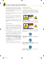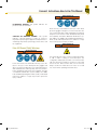
1
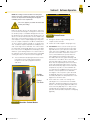
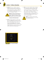
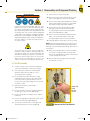
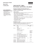
FALEX 400 Fuel
Thermal Oxidation
Test Machine
Operation and Maintenance Manual
Falex Corporation
1020 Airpark Drive
Sugar Grove, IL 60554
630.556.3669
www.falex.com
VER 1.1 (1-6-12)
F10572_F400Manual.indd 1
2/3/12 9:12 AM
Table of Contents
1
Page
Forward
.
Instructions–HowtoUseThisManual. . . . . . . . . . . . . . . . . . . . . . . 3
.
.Safety,.Safety.Label.Descriptions.and.Hazardous.Areas..
of.Test.Machine.. . . . . . . . . . . . . . . . . . . . . . . . . . . . . . . . . . . . . . . . . . 3
Section1
GeneralInformation . . . . . . . . . . . . . . . . . . . . . . . . . . . . . . . . . . . . . 5
.
1 .1.
Technical.Specifications . . . . . . . . . . . . . . . . . . . . . . . . . . . . . . . . . . . 5
.
1 .2.
Brief.Description.of.Equipment. . . . . . . . . . . . . . . . . . . . . . . . . . . . . . 5
.
1 .3.
Packing.List. . . . . . . . . . . . . . . . . . . . . . . . . . . . . . . . . . . . . . . . . . . . . 6
.
1 .4.
Getting.To.Know.The.Falex.400. . . . . . . . . . . . . . . . . . . . . . . . . . . . . 10
Section2
Setup. . . . . . . . . . . . . . . . . . . . . . . . . . . . . . . . . . . . . . . . . . . . . . . . . 15
.
2 .1.
Initial.Setup.. . . . . . . . . . . . . . . . . . . . . . . . . . . . . . . . . . . . . . . . . . . . 15
.
2 .2.
Sample.Area.and.Fuel.Preparation. . . . . . . . . . . . . . . . . . . . . . . . . . 15
.
2 .3.
Instrument.and.Test.Configuration. . . . . . . . . . . . . . . . . . . . . . . . . . . 17
Section3
SoftwareOperation. . . . . . . . . . . . . . . . . . . . . . . . . . . . . . . . . . . . . 22
.
3 .1.
Falex.400.Software.Program. . . . . . . . . . . . . . . . . . . . . . . . . . . . . . . 22
.
3 .2.
Run.Test .. .. .. .. .. .. .. .. .. .. .. .. .. .. .. .. .. .. .. .. .. .. .. .. .. .. .. .. .. .. .. .. .. .. .. .. .. .. .. .. .. .. .. .. .. . 23
.
3 .3.
Data. . . . . . . . . . . . . . . . . . . . . . . . . . . . . . . . . . . . . . . . . . . . . . . . . . 28
Section4
DisassemblyandComponentCleaning . . . . . . . . . . . . . . . . . . . . 30
.
4 .1.
Heater.Tube.Disassembly . . . . . . . . . . . . . . . . . . . . . . . . . . . . . . . . . 30
.
4 .2.
Continued.Unit.Disassembly.Cleaning . . . . . . . . . . . . . . . . . . . . . . . 31
.
4 .3.
Component.Cleaning. . . . . . . . . . . . . . . . . . . . . . . . . . . . . . . . . . . . . 31
Section5
SoftwarePreferences . . . . . . . . . . . . . . . . . . . . . . . . . . . . . . . . . . . 32
Section6
Maintenance. . . . . . . . . . . . . . . . . . . . . . . . . . . . . . . . . . . . . . . . . . . 34
.
6 .1.
Charcoal.Filter.Replacement. . . . . . . . . . . . . . . . . . . . . . . . . . . . . . . 34
.
6 .2.
Desiccant.Cartridge.Replacement. . . . . . . . . . . . . . . . . . . . . . . . . . . 34
.
6 .3.
Pump.Maintenance.(Prime,.Purge). . . . . . . . . . . . . . . . . . . . . . . . . . 36
Section7
Calibration. . . . . . . . . . . . . . . . . . . . . . . . . . . . . . . . . . . . . . . . . . . . 39
.
7 .1.
Thermocouple. . . . . . . . . . . . . . . . . . . . . . . . . . . . . . . . . . . . . 39
.
7 .2.
Differential.Pressure. . . . . . . . . . . . . . . . . . . . . . . . . . . . . . . . 40
.
7 .3.
System.Pressure. . . . . . . . . . . . . . . . . . . . . . . . . . . . . . . . . . . 41
.
7 .4.
Factors . . . . . . . . . . . . . . . . . . . . . . . . . . . . . . . . . . . . . . . . . . 41
F10572_F400Manual.indd 1
2/3/12 9:12 AM
Table of Contents
Section8
Service. . . . . . . . . . . . . . . . . . . . . . . . . . . . . . . . . . . . . . . . . . . . . . . 42
.
8 .1.
Software.Accessible.Service. . . . . . . . . . . . . . . . . . . . . . . . . . . . . . . 42
.
8 .2.
Alarm.Log . . . . . . . . . . . . . . . . . . . . . . . . . . . . . . . . . . . . . . . . . . . . . 42
.
8 .3.
Fault.Indicators . . . . . . . . . . . . . . . . . . . . . . . . . . . . . . . . . . . . . . . . . 42
.
8 .4.
Alarm.and.Warning.Messages . . . . . . . . . . . . . . . . . . . . . . . . . . . . . 43
2
AddendumA PartsListing. . . . . . . . . . . . . . . . . . . . . . . . . . . . . . . . . . . . . . . . . . . 46
AddendumB FileTransferMessage. . . . . . . . . . . . . . . . . . . . . . . . . . . . . . . . . . . 47
Notes:
F10572_F400Manual.indd 2
(Blankpageforcustomernotes). . . . . . . . . . . . . . . . . . . . . . . . . . 48
2/3/12 9:12 AM
3
Forward: Instructions–How to Use This Manual
This manual provides information and procedures to
safely install, operate, and maintain the Falex 400 Thermal Oxidation Test Machine, in future refered to as Falex
400. For your own safety and protection from injury, carefully read, understand and observe the safety instructions described in this manual.
Keep this manual with the machine. If you lose this
manual or need an additional copy, please contact
Falex Corporation.
The information contained in this manual was based on
machines in production at the time of publication. Falex
Corporation reserves the right to change any portion of
this information without notice.
This operation manual is divided into sections and
addenda as listed in the “Table of Contents”. Sections
not relevant to this machine will have a page inserted
stating so.
Safety Introduction
The following safety precautions are published for your
information. This manual does not purport to detail
all of the safety concerns, if any, associated with the
equipment’s use. It is the responsibility of the user of this
equipment to establish appropriate safety and health
practices and determine the applicability of regulatory
limitations prior to use.
This machine is built with user safety in mind; however,
it can present hazards if improperly operated and
serviced. Follow operating instructions carefully! If
you have questions about operating or servicing this
equipment, please contact Falex Corporation.
This equipment should only be operated by personnel trained by Falex or a Falex approved distributor.
This operation manual contains HAZARD, WARNING,
and CAUTION callouts, which must be followed to
reduce the possibility of personal injury, damage to the
equipment, or improper service.
The Falex 400 must be electronically grounded. Do not
change the grounding requirements of the instrument.
Machine Safety Labels
and Manual Safety Callouts
The following are safety labels placed in areas on the
test machine that may be hazardous to the operator.
These same symbols may be used in the manual to bring
attention to safety concerns. Please take caution and
understand what these labels indicate before operating
the test equipment.
CAUTION
Hot Surface.
Do NOT touch.
. or
Allow to cool before
servicing.
HOT SURFACE HAZARD: This symbol indicates hot
surface areas on the test machine. Use caution when
working in these areas where components could be hot.
WARNING
ELECTRIC SHOCK
HAZARD.
This equipment is to be
serviced by trained
personnel only.
. or
ELECTRICALSHOCKHAZARD:This symbol indicates
hazardous voltage is present when opening the
electrical cabinet. This unit is to be serviced by trained
personnel only.
WEAR SAFETY GLOVES: This symbol indicates
chemicals that may be hazardous to handle. Wear
safety gloves.
WEAR BREATHING PROTECTION: This symbol
indicates fumes that may be hazardous to inhale. Wear
breathing protection.
WEAREYEPROTECTION:This symbol indicates eye
protection need during operation.
F10572_F400Manual.indd 3
2/3/12 9:12 AM
Forward: Instructions–How to Use This Manual
4
WARNING
FLAMMABLE HAZARD: This symbol indicates the
products used are flammable.
CAUTION OR WARNING SYMBOL: This symbol
indicates a general warning or caution. A caution is
important for protecting the equipment and performance.
A warning is important to protecting yourself, others, and
the equipment.
Falex 400 General Safety Warnings
.
.
Desiccant may cause irritation to the eyes or skin. Wear
protective goggles and gloves; avoid contact with skin,
eyes, and clothing. Use in well ventilated areas and keep
away from heat or flame. Follow all Material Safety Data
Sheet (MSDS), Hazardous Materials Identification System (HMIS), ISO 9000, Lab Standard Operating Procedures (SOP), and related instructions. Failure to comply
may result in personnel injury or death.
WARNING
WARNING
.
.
.
Fuels and solvents are flammable and may cause irritation to the eyes or skin. Wear protective goggles and
gloves; avoid contact with skin, eyes, and clothing. Use in
well ventilated areas and keep away from heat or flame.
Follow all Material Safety Data Sheet (MSDS), Hazardous Materials Identification System (HMIS), ISO 9000,
Lab Standard Operating Procedures (SOP), and related
instructions. Failure to comply may result in personnel
injury or death.
F10572_F400Manual.indd 4
The heater tube test section can reach high temperatures
of 180 °C–380 °C during a test based upon test
configuration. Always place bus bar cover over the heater
tube test area when running test to prevent contact with
the test section. When the bus bar cover is removed,
always assume the heater tube test section is hot and
use caution when operating around this area.
2/3/12 9:12 AM
5
Section 1: General Information
1.1 Technical Specifications
Machine Weight: 150 pounds
Machine Footprint: 16¾ in wide x 20¼ in deep x 30 in high
Recommended Working Space: It is recommended
that 12in be left on both sides and 6in at the back of
the machine. This is to allow the Lexan cover to swing
and access to the USB port. Include area needed for
cleaning pan.
Machine Power: 120V/60Hz 220V/50/60Hz
The F400 requires a dedicated service with a ground
and a breaker sufficient to supply 10 amps to the
120V units and 5 amps for the 220V units.
1.2 Brief Description Of Equipment
The Falex 400 Fuel Thermal Oxidation Test Machine is
designed to measure the high temperature stability of
gas turbine fuels. It subjects the test fuel to conditions
that occur within gas turbine engine fuel systems. It
meets ASTM D3241, IP 323 and ISO 6249 standards. It
is robust, reliable and compact. ASTM D3241 Thermal
Oxidation Stability of Aviation Turbine Fuels requires a
strict conformance for the jet fuel industry for this critical
test. The Falex 400 matches results due to the critical
equipment specification that controls the heater test
section and test conditions.
The Falex 400 has been designed for years of operation,
it provides traceability, long maintenance intervals, and
reliable results.
Other features of the Falex 400:
• Automatic aeration and fuel sequence during
an ASTM D3241 test
• Priming is simple with easy access and
processor control
• Certified thermocouples guarantee accuracy
This machine utilizes Falex Heater Tube specimens.
Falex certifies these tubes meet all of the ASTM D3241
requirements for dimensions, surface finish and material.
Falex has proven to meet the requirements of ASTM
D3241 through participation and successful completion
of an ASTM sactioned equivalency program.
Falex Corporation does not guarantee any specific test
results or desired functionality of this equipment outside
of its intended usage.
F10572_F400Manual.indd 5
2/3/12 9:12 AM
Section 1: General Information
6
1.3 Packing List
1. The following items are included in the package:
• 1 Falex 400 Thermal Oxidation Stability Tester
• 1 Start-Up Kit
• 1 CD Manual
Table 1: Start-Up Kit Contents
Quantity
1 Package of 2
Description
Part Number
Pack of insulation bushings
400-018-003
Bus Bar Drip Pan
400-021-006
1 Package of 5
Charcoal filter
400-025-002
1 Package of 2
Metal Pre-Filter screen
400-027-003
1
Heater tube holder
assembly
400-103-009
1
Aeration line assembly
400-105-002
1
F10572_F400Manual.indd 6
Picture
2/3/12 9:12 AM
7
Section 1: General Information
Start-Up Kit continued
Quantity
Part Number
1
Sample output line
assembly
400-105-028
1
Fuel heater tube holder
input line assembly
400-105-004
1
Fuel heater tube holder
output line assembly
400-105-005
1
Pre-Filter assembly
400-105-010
1
Sample input line assembly
400-105-020
1
Lead calibration holder with
melted lead
400-108-004
1
Falex 400 Manual CD
400-112-001
1
DP calibration bottle
400-200-005
Heater Tubes with DP filters
and O-rings
400-560-001
1 Package of 12
F10572_F400Manual.indd 7
Description
Picture
2/3/12 9:12 AM
Section 1: General Information
8
Start-Up Kit continued
Quantity
Description
Part Number
1 Package of 25
O-ring tubing
620-005-002
1 Package of 5
O-ring Pre-Filter
620-210-001
2
Beaker, 1000 ml
648-400-012
1
Funnel, large
648-400-003
Funnel filter papers
648-400-011
Pre-Filter filter papers
648-400-005
1
Cleaning brush
648-400-006
1
Hex wrench
648-400-007
1
Cleaning pan,
stainless steel
648-400-008
1
Ceramic insulator
removal tool
648-400-009
1 Package of
100
1 Package of 25
F10572_F400Manual.indd 8
Picture
2/3/12 9:12 AM
9
Section 1: General Information
Start-Up Kit continued
Quantity
Description
Part Number
1
Tweezers
648-400-010
1
Thermocouple - fuel
sample
650-009-055
1
Thermocouple - heater tube
650-009-064
1
Power cord
1
Pump priming syringe
650-049-021B
1
Keyboard and Mouse
650-204-048
1
Stylus
650-204-065
1
Mouse Pad
657-100-019
1
Quality Control Certificate
of Inspection
Picture
650-030-140 (120VAC)
or 650-030-150 (220VAC)
Oxidation
Stability Apparatus
Tube Kit
p/n
400-560-003
Material: 316 Stainless Steel
Form number: 400-111-006
Falex Corporation | 1020 Airpark Drive, Sugar Grove, IL 60554 USA | (630) 556-3669 | f: (630) 556-3679 | www.falex.com
CERTIFICATE OF INSPECTION
Tube Kit
p/n
400-560-003
The enclosed test pieces have been inspected and meet
the following requirements:
Material: 316 Stainless Steel
Manufactured in conformance with:
QA Manager: ______________________________ Date: ___________
USA: (630) 556-3669 | [email protected]
F10617_PackagingInsert.indd 1
F10572_F400Manual.indd 9
ISO 9001:2000
Europe: +32 (0)16 407 965 | [email protected]
3/1/11 10:09 AM
2/3/12 9:12 AM
Section 1: General Information
10
1.4 Getting To Know The Falex 400
Front USB
Slot
DP Calibration
High Alignment
Line
Desiccant
Chamber
Door
Fault Indicators
(Resettable Fuses)
Touch Screen
Interface
On/Off Switch
Air Flow Meter
Ring Stand
Assembly
Coolant
Flow Meter
DP+
Calibration
Alignment
Line
Sample
Container
Area
Sample
Test Area
Pump Priming
Door
Figure1
F10572_F400Manual.indd 10
FuelThermalOxidationTester–Front
2/3/12 9:12 AM
11
Section 1: General Information
Fans — DO NOT BLOCK
Interface Panel
USB (2)
Ethernet (1)
Circuit Breaker
Power Plug
Receptical
Figure2
RearoftheFalex400120VUnit
Fans — DO NOT BLOCK
Interface Panel
USB (2)
Ethernet (1)
Circuit Breaker
Power Plug
Receptical
Figure3
F10572_F400Manual.indd 11
RearoftheFalex400220VUnit
2/3/12 9:12 AM
Section 1: General Information
Sample input
line assembly
400-105-020
12
Sample output
line assembly
400-105-028
Thermocouple
- fuel sample
650-009-055
Aeration line
assembly
400-105-002
Beaker, 1000 ml
648-400-012
Beaker, 1000 ml
648-400-012
Figure4
SampleContainerArea
Aeration line
assembly
400-105-002
Sample output
line assembly
400-105-028
Sample input
line assembly
400-105-020
SampleContainerAreaLines Note.that.the.
sample-in.line.is.longer.than.the.aeration.line .
Figure5
F10572_F400Manual.indd 12
2/3/12 9:12 AM
13
Section 1: General Information
Bus Bar Thermocouple
400-103-004
DP- Port (Out)
Thermocouple
- heater tube
650-009-057
DP+ Calibration Line
DP+ Port (Out)
Upper Bus Bar
Heater Tube
Thermocouple
Retaining Clip
DP Filter Housing
(behind fuel out
line)
Fuel heater tube holder
output line assembly
400-105-005
Fuel Bypass Line
Part of 400-103-009
Heater tube holder
assembly
400-103-009
Fuel heater tube holder
input line assembly
400-105-004
Pre-Filter assembly
400-105-010
Lower Bus Bar
Pre-Filter Bulkhead
Figure6
F10572_F400Manual.indd 13
SampleTestArea
2/3/12 9:12 AM
Section 1: General Information
14
Heater Tube Holder
Assembly Hex Nut
977-438-001
Upper insulation bushing
400-018-003
O-ring
650-008-002
Lower insulation bushing
400-018-003
Fuel heater tube holder
output line assembly
400-105-005
Bypass Line (part of
heater tube holder
assembly)
Lower insulation bushing
400-018-003
DP Filter Housing
(part of heater tube
holder assembly)
O-ring
650-008-002
Upper insulation bushing
400-018-003
Heater Tube Holder
Assembly Hex Nut
977-438-001
Heater tube holder
assembly
400-103-009
Figure7
ComponentsForAssemblyofTestSectionArea
Pre-Filter Screws
Lower Pre-Filter Cover Assembly
400-105-014
O-ring Pre-Filter
620-210-001
Pre-Filter filter paper
648-400-005
Metal Pre-Filter screen
400-027-003
Upper Pre-Filter Cover Assembly
400-105-021
Fuel heater tube holder
input line assembly
400-105-004
Figure8
F10572_F400Manual.indd 14
ComponentsForAssemblyofPrefilter
2/3/12 9:12 AM
15
Section 2: Setup
2.1 Initial Setup
1. Plug the Power Cord into the rear of the Falex 400.
NoTe: The sample thermocouple can be stored in
the hole at the left of the beaker area when not in use
[Figure 10].
2. Plug the power cord (120V, 60Hz, 220V, 50/60Hz)
into an appropriate outlet. Electrical source
must have a good ground or an isolated power
with ground.
2. Grasp the ring stand assembly and pull from the
housing [Figure 11a]. After the ring stand assembly is
fully extended from the housing, rotate to the right
to lock into position [Figure 11b].
3. Connect a Printer to one of the USB or Ethernet
port on the rear of the machine. See page 31 for
instructions to load printer driver.
3. Place the funnel into the ring stand and place a
clean filter paper into the funnel [Figure 12].
4. Turn the unit on (by the the rocker switch on the
front of the unit) and allow to warm up for 15
minutes prior to use.
5. The Falex 400 is shipped with a charcoal filter
located in the beaker stand. Remove the shipping
filter by sliding the filter out of the opening on the
left side of the beaker stand and replace with a
new filter. It is recommended that this filter be
replaced every 2 weeks to 1 month depending
on usage. See section 7.1 for charcoal filter
replacement instructions.
2.2 Sample Area And Fuel Preparation
Sample
Thermocouple
Sample-In Line
Aeration Line
Glass Beaker
Setup will take approximately 20 min.
1. Place a clean, empty glass beaker in the samplein position at the left of the sample container area.
Connect the aeration line and the sample-in line to
the appropriate fittings on the front panel [Figure 9].
Fittings should be finger tight. Place the aeration
and sample-in lines into the glass beaker, letting
end of sample-in line rest on bottom of beaker.
Plug in the sample thermocouple and place the
thermocouple into the glass beaker.
Figure10
ThermocoupleStorage
Filter Paper
Figure9
Sample-InBeakerArea
Figure11a
RingStandAssembly
Figure11b
RingStandAssembly
Funnel
Ring Stand
Figure12
F10572_F400Manual.indd 15
Funnel/Filter Setup
2/3/12 9:12 AM
Section 2: Setup
New O-ring
16
Damaged O-ring
Figure14a
O-ringInspection
Figure14b
O-ringPlacement
Beaker
Filter/Funnel
Figure13
FilteringFuel
WARNING
.
.
.
Fuels and solvents are flammable and may cause
irritation to the eyes or skin. Wear protective goggles, gloves, and an apron; avoid contact with skin,
eyes, and clothing. Use in well ventilated areas and
keep away from heat or flame. Follow all Material
Safety Data Sheet (MSDS), Hazardous Materials
Identification System (HMIS), ISO 9000, Lab Standard Operating Procedures (SOP), and related instructions. Failure to comply may result in personnel injury or death.
4. Using the graduations on the side of a clean
beaker, pour appropriate amount of fuel into the
beaker per the method. A minimum of 500 ml
may be used. Slowly add the fuel into the filter/
F10572_F400Manual.indd 16
funnel until all the fuel has been placed into the
filter [Figure 13]. Place the now empty beaker in the
sample-out position at the right of the sample
container area.
5. Place an O-ring on the sample-out line. O-rings
are required on all tubing lines except the aeration
and sample-in lines. Place a clean small O-ring
(650-005-002) at the end of each line before
securing the line in place [Figure 14aand14b]. Inspect
the O-rings and replace if damaged or missing.
6. Connect the sample-out line to the appropriate
fitting on the front panel [Figure 4].
7. Once the fuel has been filtered, remove the filter
and dispose of it according to local regulations.
8. Remove, clean, and store the funnel.
9. Rotate the ring stand assembly to the left and
store into the ring stand housing of test machine
[Figure 11].
2/3/12 9:12 AM
17
Section 2: Setup
2.3 Instrument And Test Configuration
the riveted end down and the tube ID number
closest to the DP filter housing. Secure the heater
tube to the top of the heater tube housing using
the lower insulator bushing with the flare facing
end of tube, O-ring (supplied in the heater tube
kit), upper insulator bushing, and hex nut [Figure 15].
Finger tighten loosely.
NoTe: Before instrument setup, all components must
be clean. If the components are not clean, review the
Component Cleaning section [seesection4.3]. A new
heater tube, DP test filter and three O-rings are required
for each test.
1. Retrieve a new heater tube kit from the box of
specimens.
2. Carefully remove the new heater tube from the
container. Wear gloves and handle the heater tube
by the ends only. Do not touch the center section
of the tube.
3. Inspect the center section of the tube for
scratches, unpolished areas, or other visual
defects. Ensure the tube is not bent by rolling it
on a flat surface. If the tube is bent or has other
defects, discard that tube and retrieve another kit.
It is advisable to write the tube number down as
this number is a required entry value on the test
configuration setup.
4. Assemble the test section. Insert the heater
tube into the heater tube housing so that it is
approximately in the center of the housing with
5. Position the heater tube inside the housing by
looking though the fuel discharge hole (DP filter
housing) and centering the heater tube shoulder
in the hole so that the shoulder is lined up with the
center of the bypass line [Figure 16].
6. Secure the heater tube to the bottom of the heater
tube housing using the lower insulator bushing
with flare facing the end of the tube, O-ring
(supplied in heater tube kit), upper insulator
bushing, and hex nut. Finger tighten loosely.
7. Finger tighten the hex nuts on both ends of the
heater tube housing firmly.
NoTice: Overtightening will break the ceramic
bushings and can cause leaks.
Hex Nut
Heater Tube
Upper Insulator Brushing
O-ring
Lower Insulator Housing
Heater Tube
Housing
Heater Tube
Shoulder
Figure15
F10572_F400Manual.indd 17
HeaterTubeInstallationComponents
Figure16
HeaterTubePosition
2/3/12 9:13 AM
Section 2: Setup
8. Using clean tweezers, install the DP filter supplied
in the heater tube kit into the DP filter housing.
Ensure the blue stripe is facing out. If the blue
stripe is missing, then that filter has already been
used so do not use it [Figure 17a]. A new DP filter
must be used for each test. Place a new O-ring,
supplied in the heater tube kit, on top of the DP
filter and push into place [Figure 17b].
DP Filter
18
DP Filter Housing
9. Attach the large end of the fuel-out line to the DP
filter housing [Figure 18]. Finger tighten.
10. Inspect the O-rings on the fuel-out and bypass
lines. Replace if missing or damaged.
11. Remove the right retaining screw of each bus
bar cap using the hex wrench supplied. Loosen
the left retaining screw of each bus bar cap
using the hex tool, so that the cap is free to pivot
on the screw [Figure 19]. To remove any fuel that
may have seeped on to the bus bars, clean the
bus bar contacts and bus bar caps, focusing
on the portions that comes in contact with the
heater tube.
Figure17a
O-ring
DPFilterInstallation
DP Filter Housing
Attach Fuel-Out Line Onto
Assembled DP Housing
Fuel-Out Line
O-ring
Figure17b
Figure18
AssembledTestSection
Figure19
F10572_F400Manual.indd 18
DPO-ringInstallation
RemovingRightBusBarScrew
andLooseningLeftScrew
2/3/12 9:13 AM
19
Section 2: Setup
NoTe: The bus bar caps and contacts are
a matched set. If the caps are completely
removed from the contacts, match the
number stamped on the inside of each
cap to the number stamped on the end of
the contact.
Bus Bar Caps
Bus Bar
Contacts
12. Install the assembled test section into the
sample test area [Figure 20]. Place the assembled
test section in the groove between the bus bar
contacts and bus bar caps serial number side up.
Insert both right hand retaining screws and loosely
finger tighten.
Heater Tube
13. Align the top of the heater tube so that it is flush
with the top of the bus bar contact [Figure 21].
Assembled
Test Section
14. When the test section is properly aligned, tighten
the upper and lower bus bar screws with the
hexagon wrench provided.
15. Attach the fuel-out line to the DP- fitting and fuel
bypass line to the DP+ fittings [Figure 22]. Finger
tighten the fittings.
Figure20
InsertingTestSectionInstallation
Fuel-Out
Line To
DP- Fitting
Fuel Bypass
Line To DP+
Fitting
Figure21
TubeAlignedWithTopof
Figure22
Fuel-OutandFuelBypassLines
Bus Bar
F10572_F400Manual.indd 19
2/3/12 9:13 AM
Section 2: Setup
16. Begin assembling the pre-filter by placing the
pre-filter O-ring on the lower housing [Figure 23].
17. Place the pre-filter screen into the upper housing
[Figure 23].
18. Using clean tweezers, remove a new pre-filter filter
paper from the protective case and place onto the
pre-filter screen.
NoTe: There are two blue paper spacers
between each pre-filter filter paper. Do not
use blue spacer paper. Use only the white
pre-filter element. Use of the blue spacer
paper will cause the test to fail.
20
Place the lower housing onto the upper housing.
Line up the screw holes on the upper and lower
housings and insert the screws through the lower
housing into the upper housings [Figure 23]. Finger
tighten the screws with the hexagon wrench.
19. Inspect the O-ring on the end of the pre-filter
assembly. Replace the O-ring if missing or
damaged.
20. Connect the pre-filter assembly to the pre-filter
bulkhead fitting and finger tighten [Figure 24].
Pre-Filter Screws
Lower Pre-Filter
Housing
Pre-Filter O-ring
Pre-Filter
Bulkhead Fitting
Pre-Filter Assembly
Pre-Filter Paper Filter
Pre-Filter Metal Screen
Upper Pre-Filter
Housing
Fuel Input Line
Figure23
F10572_F400Manual.indd 20
Pre-FilterComponents
AttachingthePre-Filter
Assembly
Figure24
2/3/12 9:13 AM
21
Section 2: Setup
21. Attach the pre-filter assembly to the assembled
test section using the fuel input line [Figure 25].
Inspect the O-rings on both ends of the sample
line union. Replace if missing or damaged.
NoTe: The heater tube thermocouple can be stored in
the hole found on the top right of the beaker stand to
the left of the bus bar area when not in use [Figure 26b].
24. Check all of the fittings to ensure they are
finger tight.
22.Finger tighten the fittings until snug.
23. Plug in the heater tube thermocouple. Carefully
insert the thermocouple tip into the hole on the top
of the heater tube and lower until it stops. Rotate
the thermocouple retaining clip to the left to lock
the thermocouple into place [Figure 26aand26b].
25. Close the acrylic cover to the sample test area.
Leaving the cover open will cause an alarm while
a test is running.
If this is the initial setup or if the F400 has not been operated for 15 days it is recommended that the automated
Purge be run prior to any tests being performed on the
unit. Refer to section 6.3.2.
Assembled
Test Section
Fuel Input Line
Pre-Filter Assembly
FuelInputLinetoAssembled
TestSection
Figure25
Thermocouple
Retaining Clip
Figure26a
F10572_F400Manual.indd 21
Insert Thermocouple
into top of Tube
ThermocoupleRetainingClip
Retaining
Bus Bar Screws Clip in Place
Heater Tube
Thermocouple
Installed
HeaterTubeThermocoupleand
RetainingClip
Figure26b
2/3/12 9:13 AM
Section 3: Software Operation
It is recommended that the user familarize themself with
the software by reading this section prior to using any
portion of it.
3.1 Falex 400 Software Program
GeNeral NoTes: Various software screens have
similar buttons which are discussed below.
HEADER:Each screen has a blue shaded header.
The center of the header has the screen title with the
date and time displayed underneath. The time is shown
in standard or military format depending on the user
preference. The headers right side may have an abort
button or a home button. The home button returns to
the Main screen while the abort button will end the
current process. The ‘?’ invokes the software version
builds on the main screen [Figure 28]. The '?' invokes a
reference for help on all other screens [Figure 27].
Screen Title
Date & Time
Lower right corner buttons: Usually there is a backward arrow, forward arrow or both [Figure 29]. The backward arrow directs the user to the previous screen and
the forward arrow advances to the next screen. In many
instances the forward arrow will not appear until certain
conditions are met on the current screen (such as; mandatory test information entered, a button pushed, a temperature value reached).
Lowerleftcornerbuttons: Buttons in the lower left are
for user assistance [Figure 29]. Various screens during a
running test have a “Status’ button which activates a Status screen. The Status screen shows live feedback of
critical test data and where that data is taken from.
Return to Main Screen (Figure 28)
Software build or
Operational Manual
Help (Figure 29)
Aborts test or
procedure
Figure27
HeaderBars
Figure28
SoftwareBuild
F10572_F400Manual.indd 22
22
Help Location
in Operation
Manual
2/3/12 9:13 AM
23
Section 3: Software Operation
Instructions
Forward
screen
and back
screen
buttons
Figure29
LowerLeftandRightButtons
The ‘RUN TEST’ menu allows users to choose various
test types and record the visual tube reading. The test
data can be viewed, printed, and/or stored after a successful test completion.
1. AccessingtheTestTypescreen: On the MAIN
SCREEN press the 'Run Test' button [Figure 31]. If
this button is not visible there will be a temperature
bar in its place [Figure 32]. This bar shows the
current heater tube thermocouple temperature
and will not allow an operator to start a new test
until the temperature drops below 40ºC, at which
time it is safe to remove the old heater tube and
set up for a new test.
The heater tube test section is extremely
hot and dangerous to handle during and
after a test has completed or aborted. Keep
the thermocouple in the heater tube after
any test has completed or aborted until its
temperature drops below 40ºC. Once the
temperature is below 40ºC the unit is safe
to handle.
The ‘Instructions’ button pops up a window to help explain how the current procedure is run [Figure 30]. These
instructions are basic and the user should refer to other
sections in this manual for a more detailed explanation
on that particular procedure. Some instructions may
have multiple pages and the arrow in the lower right corner takes you to additional instructions. Press the ‘Close’
button to exit the instructions and return to the program.
Access
Test
Sleection
Screen
Additional
pages
MainScreenIn
ReadyState
Figure31
Figure30
AdditionalPageArrow
onInstructionPages
Temperature
must be
below 40ºC
before ‘Run
Test’ button
appears
Throughout various screens will be 'factory' buttons.
‘Factory’ buttons are solely for the use of authorized
factory personnel and access to this area is protected.
3.2 Run Test
If this is the inital setup or if the unit
has not been operated for 15 days it is
recommended that the automated Purge be
run prior to any tests being performed on
the unit. Refer to section 6.3.2.
F10572_F400Manual.indd 23
Figure32
MainScreenWaitingForHeater
TubeTemperaturetoLower
2/3/12 9:13 AM
Section 3: Software Operation
2. TestTypeScreen: This screen has the possibility
of eight different test types to choose from
[Figure 33]. The D3241 ASTM test is always active
and the button cannot be deactivated. Single,
Breakpoint 1, Breakpoint 2, and the 4 Custom
tests are activated from the ‘Preference’ screen.
Active
NoTe: Only tube rating entries of 0, <1, 1,
<2, 2, <3, 3, <4, and 4 are accepted for the
breakpoint tube reading.
D. Breakpoint2: Breakpoint 2 runs a matrix of
tests checking both the visual tube reading
value (numeric, abnormal and peacock) and
the maximum ΔP value. All tests run
150 minutes.
NoTe: At the time of this printing Breakpoint 2 is not
included in the test series matrix.
E. Custombuttons1-4: Custom 1-4 buttons
allow the user to store both the test header information and the test parameters as a unique
test name. This information is retained with the
button selection until it is overwritten. Selecting a test type will advance to the respective
configuration screen
Inactive
Figure33
NewScreenShot
A. ASTM: A D3241 test commences following
the mandatory test information entry. All tests
are 150 minutes with a flow rate of 3ml/minute.
These values cannot be altered. The temperature default to the value set under ‘Preferences’ and can only be altered through the
‘Preferences’ screen.
B. Singletests: This selection allows the operator to set parameters for test duration, flow rate
and test temperature for one run. The parameters entered are not stored.
C. BreakPoint1: Breakpoint 1 runs a series of
automated tests, sequencing from the visual
tube reading numeric value only. It does
not consider the visual tube reader entry of
abnormal or peacock and does not consider
the differential pressure (ΔP). All tests run 150
minutes. Configuration allows for the operator to choose the initial control temperature
(between 180–380ºC) for the series of tests.
The operator enters a tube rating value for
each test in the series and the program automatically sets up the parameters for the next
test. Each subsequent test will automatically
increment 10ºC if the entered tube reading is
<3. There is one exception to the automated
temperature increase and that is on the second run. The operator is given the chance to
reenter his starting temperature to a higher
value if he feels the initial temperature setting
was too low. Once a reading of 3 or greater is
entered the final test in the series is initiated at
a temperature of 5ºC below the previous run.
All results are compiled into a single data file.
F10572_F400Manual.indd 24
24
3. ConfigurationScreens: All test types require
configuration prior to starting. Data File Root
Name, Lab, Operator, Tube ID Fuel Type and
Fuel ID fields can be entered by the operator,
however tube ID and the Fuel ID must be entered
before the configuration screen will display a
forward arrow allowing program advancement
[Figure 34]. Some test configurations allow for entry
of test duration, flow rate and test temperature.
All four custom configuration screens have
one additional entry field for the button name.
Information entered in the Configuration screens
is considered the header for the generated data
files and will appear on both the printed report
and the electronic file. The back arrow at the
bottom right returns to the ‘Test Type’ screen. The
forward arrow on the bottom right will only appear
once the mandatory configuration information has
been entered. The Instructions button on the lower
left opens a window with generic instructions for
setting up and running a test. Please refer to the
method for specific instructions.
Figure34
ASTMConfigurationScreen
2/3/12 9:13 AM
25
Section 3: Software Operation
A. DataFileRootName: The Data File Root
Name can be entered (maximum of 6 characters) or left with the default value. Every time
any configuration screen is entered the Data
File Root Name is Data. This can be overwritten. Every test run has a sequential number
added to the root name. Once any combination of 99 tests are run, the sequential number
resets to 01.
B. Lab: A lab name may be entered up to
15 characters in length.
Figure35
SingleConfiguration
C. Operator: An operator name may be entered
up to 15 characters in length.
D. TubeID: A tube ID entry is a mandatory entry,
The value can not exceed 15 characters. The
tube ID number can be found on the specimen tube.
E. FuelType: An fuel type may be entered up to
15 characters in length.
F.
Figure36
Breakpoint/Configuration
FuelID: A fuel ID entry is required. It may be
up to 15 characters in length.
G. TestTemperature,C: Enter a temperature.
The test will control the temperature of the
tube between 180–380˚C. Single, breakpoint
and custom test configurations allow this to be
an operator entry but on ASTM tests this is a
fixed value.
H. Duration,min: Enter a time for the test duration between 9-360 minutes. The timer begins
once the unit has reached the temperature set
point. Single and custom configurations allow
this to be an operator entry but is a fixed value
in both ASTM tests and breakpoint tests.
I.
Figure37
Figure38
F10572_F400Manual.indd 25
CustomConfiguration
FlowRate,ml/min: Enter a pump flow rate
between 2–9 ml/minute. Single, breakdown
and custom configurations allow this to be
an operator entry but it is a fixed value for an
ASTM test.
4. AerationScreens: Proceeding from the
configuration screen the aeration screen appears
[Figure 38]. The user has the choice to start aeration
or skip aeration.
AerationScreen
2/3/12 9:13 AM
Section 3: Software Operation
26
NoTe: According to D3241 aeration most take place
within 1 hour prior to heating the sample. If the operator
chooses to skip aeration a warning box will appear
reminding of the 1 hour requirement.
Be sure to properly assemble the Falex 400
before proceeding.
Begin the aeration process by pressing the ‘Start’ button. An aeration timer begins counting the 6 minutes that
the aeration pump is on. Bubbles will appear in the sample beaker from the aeration line filter. Aeration rate is at
about 1.5 L/minute when the ball is set in the middle of the
green area on the aeration flow meter on the front of the
unit. Adjust the meter as required [Figure 39]. During aeration, the sample temperature should be held between
15–32ºC and the aeration humidity to no greater than
21%. Should the sample temperature or humidity be outside of this range the test will abort. The current values
for temperature and humidity appear in the center Data
box on the screen. The Digital Points then displays status
within the system during aeration. The ‘Status’ button in
the lower left corner opens a pictorial screen of the F400
showing live values of critical measurements [Figure 40].
5. The test will automatically begin after the 6-minute
fuel aeration. As the sample is being aerated,
the previous runs fuel is purged from all lines
and valves.
Aeration
Flow Meter
Coolant
Flow Meter
Figure39
F10572_F400Manual.indd 26
Figure40
StatusScreen
6. During the aeration, inspect all fittings in the
sample test area for leaks.
7. If leaks are found, re-tighten using fingers only.
8. TestScreens: These screens remain open the
duration of a test. The Pressure box in the lower
right indicates the system pressure and the DP
value. Tests run at 3.45MPa+/- 10%. Once system
pressure is reached the heater will commence.
It is recommended that the operator watch for
leaks during this pressurization. When leaks
are visible, abort the test, tighten all fittings and
restart the test. Should the unit not reach required
pressure within 180 seconds the system will
abort. After the required pressure is reached the
heater tube temperature will increase. A system
abort will automatically happen if the heater tube
temperature set point is not reached within 90
seconds after the 3.45MPa pressure is reached.
Likewise, if the temperature is not held within
two degrees of the set point a system abort will
be triggered. When the set point temperature is
reached (Indicated in the Temperature box on the
right) the test run timer starts.
9. The bus bars are cooled once heating of the
tube begins. The coolant flow meter should be
adjusted to 10 gal/hr flow [Figure 39]. The bar at the
bottom of the screen gives graphical feedback of
the test run time [Figure 41a]. The “+” button on the
top right will open a graph with the DP, system
pressure and heater tube temperature overlapping
[Figure 41b].
AerationCoolantMeters
2/3/12 9:13 AM
27
Section 3: Software Operation
Figure41a
Testruntime
Systempressureandheater
tubetemperature
Figure41b
10. TestCompletion: Tests either complete or
they fail due to operator aborts, failure to meet
or maintain operational requirements such as
pressure loss, failure to maintain temperature
or excessive bus bar temperature. Following
test completion or failure, a safety screen
appears halting program advancement until
a safe handling temperature is reached at the
heater tube thermocouple [Figure 42]. The Tube
Temperature timer bar will disappear from the Test
Complete screen when the unit has reached a
safe temperature to proceed.
The heater tube test section is extremely
hot and dangerous to handle after a test
has completed or aborted. Keep the
thermocouple in the heater tube after any
test has completed or aborted until its
temperature drops below 40ºC. Once the
temperature is below 40ºC the unit is safe
to handle.
F10572_F400Manual.indd 27
Figure42
TestCompletionScreenWaiting
ForTubTemperatureToCool
A. TubeRating: Upon a successful test completion a tube rating screen appears following
the cool down. Follow the heater tube disassembly procedure (Section 4) to prepare the
tube for rating. The operator can enter a value
for the tube rating and pumped fuel volume or
advance without entries [Figure 43]. All entries
are stored with the data file. The tube rating
is derived from placing the specimen tube in
the Falex 420 Tube Rater and comparing it to
the ASTM D3241 color comparison standard
supplied with the Tube Rater. The Falex 420
Tube Rater is specifically designed to meet
ASTM D3241 for tube rating. Any characters
can be entered for a tube rating however if is
recommended that the individual test method
for procedure and instructions on how to rate
a tube be used.
Figure43
TubeRatingScreen
B. AbortedTests: A test is terminated by the operator pressing any abort button during a test
or from the test itself failing to reach defined
parameters. Refer to the Alarm section of this
manual to see which alarms cause an immediate test termination and which alarms initiate
only a warning message.
2/3/12 9:13 AM
Section 3: Software Operation
3.3 Data
Data: The ‘Data’ screen is accessed from the ‘Main’
screen [Figure 44] or it will automatically appear at the
completion of a successful test. The ‘Data’ menu allows
the user to retrieve the data file from the last test whether
successfully completed or not.
28
1. View: This initiates a display of the printout
information from the last run test. There are two
screens. The first ‘View Data –General’ screen
displays test information on the test [Figure 46].
Press the forward arrow to advance to the “View
Data-Pressure” screen to see the DP readings
taken every 30 minutes during the test [Figure 47].
NoTe: If the Falex 400 has had a power cycle since the
last test, data transfer cannot be performed.
The name of the last test run is on the top line on this
screen. This is the file that the first three buttons refer to
[Figure 45]. The user can view the test data on the touch
screen, transfer the data from the PLC storage onto the
computer, print this report and/or copy files from the
touch screen to a USB device or Ethernet connection.
Complete data records of DP mmHg, heater tube temperature and system pressure are taken every minute
during a test and are stored in the data file. To retrieve
the data file the operator needs to ‘Transfer’ the data file
and then ‘Copy’ the file to an external folder. Data files
are saved in .csv format and can be viewed using appropriate software.
Figure46
ViewingData
Page1-TestInformation
Figure47
ViewingData
Page2-DPValues
Access
the data
Figure44
HowToAccess
TestData
Figure45
DataFileName
Name of
data file
that View,
Transfer
and Print
refer to
F10572_F400Manual.indd 28
2/3/12 9:13 AM
29
Section 3: Software Operation
2. Transfer: After a test completion this button
MUST be selected to move the test data to the
computer. Upon transfer, data files reside in the
“Data” folder under the root directory (F400 (C:)).
An acknowledgement window appears upon
successful data transfer [Figure 48]. Do not proceed
until this acknowledgement appears.
NoTe: The current test data will be lost at
the start of the next test if this ‘Transfer’
button is not pressed or when the F400's
power is cycled. The computer has limited
hard drive space and it is recommended
that the user regularly perform file
maintenance on the “Data” folder .
4. Copy: ‘Copy’ opens Windows Explorer. Navigate
to the “Data” folder under the root directory (400
(C:)). This folder contains all the data files that
have been transferred. Close Windows Explorer
when copying is complete. For copying to external
devices there are three USB ports and one
Ethernet port located on the 400. Two USB ports
and the Ethernet port are on the convenience
outlet on the back panel. One USB port is located
on the front of the unit directly above and to the
right of the drierite window.
NoTe: Do not delete or rename the Data
folder or data transfer will not occur and test
data information will be lost.
3. Print: Pressing the print button sends the data
file to the installed printer. An internal message
appears while the data transfer is in process and
will close automatically, sample can be seen
in printout [SeeAddendumB]. Falex recommends
using the printer sold by Falex as the drivers are
installed and ready for use upon power up. Should
a different printer be used refer to the ‘Preference’
section of this manual to install a printer.
Figure48
F10572_F400Manual.indd 29
FileTransferMessage
2/3/12 9:13 AM
Section 4: Disassembly and Component Cleaning
WARNING
.
.
.
Fuels and solvents are flammable and may cause
irritation to the eyes or skin. Wear protective goggles, gloves, and an apron; avoid contact with skin,
eyes, and clothing. Use in well ventilated areas and
keep away from heat or flame. Follow all Material
Safety Data Sheet (MSDS), Hazardous Materials
Identification System (HMIS), ISO 9000, Lab Standard Operating Procedures (SOP), and related instructions. Failure to comply may result in personnel injury or death.
30
9. Remove the test section assembly.
10. Remove the fuel-out line (J-line) from the heater
tube housing and place in the pan provided.
11. Remove the O-ring and the DP filter from the DP
filter housing using the extraction tool provided.
Discard the used O-ring and the DP filter.
12. Remove the hex nuts and the upper insulator
bushings from both sides of the heater tube
housing and place them in the pan provided.
Remove and discard the O-rings.
13. Remove the lower insulator bushings from both
sides of the heater tube and the heater tube
housing and place them in the pan provided.
14. Carefully slide the heater tube out of the housing.
NoTe: Lower insulator bushings may come out of the
heater tube housing while removing the heater tube or
they may stay in the heater tube housing. Take care not
to lose them.
The heater tube test section can reach high temperatures of 180 °C–380 °C during operation. Always place bus bar cover over the heater tube test
area when running test to prevent contact with the
test section. When the bus bar cover is removed,
always assume the heater tube test section is hot
and use caution when operating around this area.
15. Rinse the heater tube with Iso-Octane and allow
the solvent to evaporate. Place the heater tube
back in the original plastic container and cap until
you are ready to rate the tube.
16. Rate the tube using an approved method and
record value on screen.
4.1 Unit Disassembly
1. Position a waste solvent container as needed to
catch solvent during the component cleaning.
2. The heater tube must be removed and rated.
Allow the heater tube assembly to cool for
15 minutes before continuing.
3. Lift and rotate the heater tube thermocouple
retaining clip off the thermocouple and carefully
remove the thermocouple tip from the hole on
the top of the heater tube taking care not to bend
the thermocouple.
4. Wipe down the thermocouple using a
germicidal wipe.
Upper And
Lower
Bus Bar
Screws
5. Remove the fuel-out line from the DP- fitting and
the fuel bypass lines from the DP+ fittings.
6. Remove the prefilter assembly from the cabinet
bulkhead.
7. Remove the right upper and lower bus bar screws
with the hex wrench provided [Figure 49].
8. Loosen the left hand screws on the upper and
lower bus bars but do not remove [Figure49].
F10572_F400Manual.indd 30
Figure49
RemovaloftheTestSection
2/3/12 9:13 AM
31
Section 4: Disassembly and Component Cleaning
4.2 Continued Unit Disassembly
17. Use the hex wrench to remove the three screws in
the pre-filter assembly.
18. Disassemble the pre-filter. Remove and discard
the white pre-filter element. Place the remaining
components of the pre-filter assembly into the
provided pan. The prefilter O-ring is reusable afer
proper cleaning.
19. Open the cover from the sample container area.
20. Remove the aeration line and the sample-in line
and place them in the pan provided.
21. Remove the fuel thermocouple from the beaker
and wipe down.
22.Remove the sample-in and sample-out
glass beakers.
4.3 Component Cleaning
NoTice: The heater tube housing is the only
component to be cleaned with Tri-Solvent.
1. Brush the inside of the heater tube housing with
the provided cleaning brush and Tri-Solvent.
2. Inspect the inner surfaces of the heater tube
housing for cleanliness and repeat step 1
if needed.
3. Rinse with Iso-Octane and dry using
compressed air.
4. Use a wash bottle filled with Iso-Octane to flush/
rinse all components in the pan and dry using
compressed air. Make certain all fuel has been
removed from all components.
23. Dispose of fuel appropriately according to
local regulations.
F10572_F400Manual.indd 31
2/3/12 9:13 AM
Section 5: Software Preferences
32
5.0 Software Preferences
The Preferences menu allows authorized users to set up
which test types can be run, the default ASTM D3241 test
temperature, date/time display options (military or standard time), and exit to Windows to install printer drivers.
Only authorized users should be given the password to
the Preference section.
1. AccessingthePreferencesscreen: On the
MAIN SCREEN press the 'Preferences' button
[Figure 50]. A pop-up box will appear on the screen
asking for a password. Enter the password and
press OK to continue.
Access
Preferences
Figure51
PreferencesScreen
A. TestSelection: This section is on the lefthand side of the screen containing seven boxes with respective titles on their right. Clicking
on these boxes will put an 'X' in the box and
activate the different test buttons available on
the TEST TYPE screen. To deactivate a test
type, click the boxes once more so that the 'X'
disappears from the box.
Figure50
Accessing
Preferences
2. PreferencesScreen: After the password is
entered, the Preference screen appears [Figure 51].
There are four areas to this screen. First there is
the 'Test Selection' section to the left-hand side of
the screen containing seven test types, a ‘Time’
section containing selections for the date/time
format, an ‘Install Printer’ button for access to
the Windows Control Panel for adding additional
printers, and a value box labeled ‘ASTM Temp, C:’
to set the stored ASTM test temperature.
A ‘Single’ test allows the user to enter all the
test header information and all the test parameters. A single test runs one test with these
parameters. They are not saved when the
machine‘s power is cycled.
‘Breakpoint1’ follows the breakpoint method
described inn ASTM D3241. It is based only
on the VTR (visual tube reader) integer value
entered at the completion of each test section.
‘Breakpoint2’ is a matrix method used to
determine the fuel’s breakpoint but takes into
consideration the VTR readings with the A
(abnormal) and P (peacock) attributes and the
DP value. The only test parameter the user
may enter is the starting temperature.
There are four custom tests the user can
choose. Each ‘Custom’ test allows the user to
enter all the test header information and the
test parameters. Once they are entered they
are stored in the unit even through
power cycles.
B. Time: On the right-hand side of the Preferences screen, there is a box labeled 'Time.' In
this box, there are two buttons 'Mil' and 'Std.'
These stand for 'Military' and 'Standard' time
respectively and will change the format of the
time display on the machine.
F10572_F400Manual.indd 32
2/3/12 9:13 AM
33
Section 5: Software Preferences
C. InstallPrinter: Pressing the ‘Install Printer’
button will initiate the Windows Control Panel.
Select the 'Printers and Faxes' icon in the
Window’s Control Panel and then select 'Add
Printer.' Users can also install a printer driver
from a flash drive.
Printer drivers: Falex does not guarantee the use of any
printer with its software other than the one shipped with
the unit.
D. SetPCTime: This button takes you out to
Windows Control Panel that allows you to
navigate to Date & Time. Once you have set
the correct date and time, cycle the power by
turning the unit off and then on.
E. ASTMTemperature: This is where a default
test temperature can be stores for all ASTM
tests. For instance, some specifications
require 270ºC rather than the default value of
260ºC.
F10572_F400Manual.indd 33
2/3/12 9:13 AM
Section 6: Maintenance
6.1 Charcoal Filter Replacement
34
Desiccant Cover
To prevent equipment contamination, the
charcoal filter must be changed monthly.
Failure to follow this warning may result in
damage to equipment.
1. Ensure the Falex 400 is not performing a test.
2. Open the beaker cover by tilting it out
towards you.
3. Slide the used charcoal filter out of the slot on the
left side of the beaker stand [Figure52].
4. Properly dispose of the charcoal filter.
5. Slide a new charcoal filter into the slot on the left
side of the beaker stand.
Figure53
DesiccantCartridgeLocation
DO NOT use the ethernet port in the
desiccant chamber. It is for use by Falex
technicians only.
1. Change the desiccant cartridge when 75–90%
most of the desiccant granules turn from blue
to pink.
Figure52
Charcoal Filter
6.2 Desiccant Cartridge Replacement
.
2. Be sure the Falex 400 is powered off. Locate
the desiccant cover on the front of the Falex 400
[Figure53].
3. While holding the desiccant cover in place, use
a flat-tipped screwdriver to loosen six flathead
screws until the cover can be removed [Figure54].
These screws are captivated and will not come
apart from the cover.
.
Desiccant may cause irritation to the eyes or skin.
Wear protective goggles, gloves, and an apron;
avoid contact with skin, eyes, and clothing. Use
in well ventilated areas and keep away from heat
or flame. Follow all Material Safety Data Sheet
(MSDS), Hazardous Materials Identification System
(HMIS), ISO 9000, Lab Standard Operating Procedures (SOP), and related instructions. Failure to
comply may result in personnel injury or death.
Figure54
F10572_F400Manual.indd 34
DesiccantCartridgeMountedIn
Housing
2/3/12 9:13 AM
35
Section 6: Maintenance
4. Grasp the desiccant cartridge with one hand
and pull the desiccant cartridge straight out of
the machine. If rubber bushings are attached
to desicant filter, remove and replace in
machine [Figure55]. Properly dispose of used
desiccant cartridge.
5. Obtain a new desiccant cartridge [Figure56].
6. Align the new desiccant cartridge with the
desiccant cartridge inlet/outlet ports. Push
the desiccant cartridge straight into the F400
desiccant housing until the cartridge snaps into
the retainer clips.
7. Power on the machine, and proceed to
maintenance screen. Push the aeration button.
Verify the humidity level is dropping. If it is not,
the dessicant is not seated correctly in the rubber
bushing. Remove dessicant cartridge, reposition
rubber bushing and reinstall cartridge.
Figure56
DesiccantCartridge
8. Once the cartridge is properly installed. replace
desiccant cover and install six screws to secure.
Desiccant Housing
Retainer Clips
Desiccant Cartridge Inlet/Outlet Ports
Rubber Bushings
Figure55
F10572_F400Manual.indd 35
DesiccantCartridgeHousing
2/3/12 9:13 AM
Section 6: Maintenance
6.3 Pump Maintenance
6.3.1 Prime Pump
WARNING
.
.
.
36
.
Fuels and solvents are flammable and may cause
irritation to the eyes or skin. Wear protective goggles, gloves, and an apron; avoid contact with skin,
eyes, and clothing. Use in well ventilated areas and
keep away from heat or flame. Follow all Material
Safety Data Sheet (MSDS), Hazardous Materials
Identification System (HMIS), ISO 9000, Lab Standard Operating Procedures (SOP), and related instructions. Failure to comply may result in personnel injury or death.
Air in the lines is indicated by visible air pockets in the
sample output line, the lack of fuel being expelled; or
the lack of a steady stream of fuel expelled through the
sample-out line while the pump is running (assuming
fluid is in the sample beaker and the supply in line is
properly installed). It is recommended the first attempt
to free the system of air is to run the automated ‘Prime’.
If after running the ‘Prime’ for 2-3 minutes and a steady
fluid flow is not achieved, the automated ‘Purge’ should
be used. Should the ‘Purge’ not produce a steady flow
the manual prime pump method can be used. Access
the automated methods thru the maintenance software
screen. The ‘Maintenance’ screen is accessed from the
‘Main’ screen [Figure 57].
Select the Prime button on the maintenance screen
[Figure58]. Before beginning the Prime Pump operation be
sure the sample beaker has plenty of fluid, 250 mls allows for 15 minutes of priming. Attach the sample-in line
properly, placing the filter end into the beaker. Attach the
sample outline and be sure there is a beaker under the
properly attached sample-out metal line [Figure59]. Pressing the Start button begins an automated prime pump
sequence. The appropriate valves are open and closed
as needed as can be seen by the lighted Digital Point
(green=open, red=closed). The pump is adjusted to a
flow rate of 9 ml/minute during this prime. The Status bar
returns feedback during the prime sequence. There is no
time limit to the prime sequence and the operator must
press the Stop button to end the pump priming.
Watch the fuel flow into the outlet beaker. When a steady
stream is reached (no air in the line) the priming is successful. Should air pockets still be visible in the lines,
proceed to the purge sequence. If the prime pump did
remove all air pockets, dispose of the fuel properly and
begin testing.
Figure58
MaintenanceScreen
Figure59
PrimePumpScreen
Access
Maintenance
Screen
Figure57
F10572_F400Manual.indd 36
AccessingThe
MaintenanceScreen
2/3/12 9:13 AM
Section 6: Maintenance
37
6.3.2 Priming Pump
6.3.2.1 Manual Method
Although not the recommended method, the pump and
lines may be primed manually.
1. Open the sliding door in front of the pump by
gently pressing the black handle in and sliding the
door to the left [Figure60].
2. Place a towel under the two pump heads.
3. On the main screen, select the MAINTENANCE.
On the maintenance screen, select PRIME.
4. Press the PRIME button.
5. Insert an empty, plastic 10 ml syringe into the
pump priming port at the center of the black
priming port knob [Figure61]. Rotate black priming
port knob counterclockwise and suction fuel out
of the pump priming port by pulling in the syringe
plunger. Allow 6–8 ml fuel to fill syringe. Close
the black priming port knob by turning clockwise.
Remove the syringe from the black priming port
knob and dispose of fuel appropriately.
Black Handle
OpeningtheDoor
toPrimethePump
Figure60
Black Priming Port Knob
Plastic Syringe
Two Pump Heads
Figure61
F10572_F400Manual.indd 37
PrimingthePump
2/3/12 9:13 AM
Section 6: Maintenance
38
6.3.3 Purge
The Purge cycle should be performed the first time the
Falex 400 is started, whenever the unit has sat unused for
30 days or more or whenever there is air in the lines and
the prime pump sequence failed to remove all the air.
Select the Purge button from the maintenance screen.
[Figure58] Before beginning the Purge Pump operation be
sure the sample beaker has at least 400 mls fluid and
attach the sample-in line properly, placing the filter end
into the beaker. Be sure there is a beaker under the properly attached sample-out metal line. Pressing the Start
button begins an automated prime pump sequence that
cannot be stopped once started [Figure62].It's purpose is
to flush every line in the system with new fuel and expell
any air pockets. The purge sequence runs 21 minutes.
Valves are open and closed in sequence as can be seen
by the lighted Digital Points. The pump is adjusted to a
flow rate of 9 ml/minute. The Status bar returns feedback
of the purge sequence and the timer bar gives feedback
on how much time is remaining.
Figure62
PurgeScreen
Following a successful purge all air should be removed
from the lines. Dispose of used fuel properly and begin tests.
F10572_F400Manual.indd 38
2/3/12 9:13 AM
39
Section 7: Calibration
Calibrations should be preformed regularly on the 400
in accordance with the method. Refer to each method
for it is required calibration schedule. Calibrations should
be performed on the heater tube thermocouple, the differential pressure transducer and the system pressure.
‘Thermocouple’ allows for a calibration of the temperature
control system using ice and the eutectic temperature of
lead to calibrate the heater tube thermocouple. The differential pressure is the measurement across the DP test
filter. Excessive differential pressure (DP) is an indication
of poor fuel quality. ‘Diff Press’ provides a calibration of
the differential pressure transducer. ‘Sys Press’ allows for
adjustment of the pressure measurement against a NIST
certified reference pressure gage.
Select
Thermocouple
7.1.1 Thermal Calibration Lo Check
1. Prepare a low temperature standard, from an ice
bath of distilled water and crushed distilled water
ice (an insulated cup works best).
2. Place the heater tube thermocouple in the
ice bath.
3. Stir the thermocouple in the bath watching the
tube temperature on the display [Figure64].
4. Continue stirring until the tube temperature no
longer drops and holds constant for 20–30
seconds. Press the ‘Accept’ button. This will
store the observed low temperature and will
initiate the Thermocouple Hi Check display. The
thermocouple reading should be accepted if
the displayed value is 0.1˚C ±2˚C. Should the
thermocouple not reach this value, verify the ice
bath is not contaminated. If it still will not reach an
acceptable value, replace the thermocouple.
Current
Thermocouple
Reading
Figure63
7.1 Thermocouple
The auto calibration performs a calibration of the heater
tube thermocouple by a ‘low’ calibration check using an
ice bath and a ‘high’ calibration procedure using the lead
calibration assembly. It is critical that the following steps
be followed carefully. Failure to have the thermocouple in
the correct position during each step can cause the unit
to continue to apply heat to the bus bars or fail to heat the
bus bars. should a step not complete as documented
within seven minutes of initiation, shut the unit off
from the power switch on the front, allow the unit to
cool for a minimum of 20 minutes before restoring
power and re-initiating calibration.
1.
[Figure63]From
the Main Menu, go to the
Maintenance > Calibrate > Thermocouple display
and select ‘Auto Calib’ button. This will reset the
previous calibration factors to the default values
(0 ºC factor = 0 and 327.5 ºC factor = 327.5). It
will also call up the ‘Thermocouple Calibration Lo
Check’ display.
F10572_F400Manual.indd 39
Figure64
ThermocoupleLo
CheckScreen
7.1.2 Thermocouple Calibration
Hi Check
1. Install the lead calibration check assembly in the
upper/lower bus bars. Make sure the top of the
assembly is flush with the top of the upper bus bar
and that the bus bar screws are tight.
Manual insertion and removal of the
thermocouple is required during the Hi
Check. Care should be taken during all
steps as the bus bars are extremely hot
and can carry high current. Only insert
and remove the thermocouple by the
insulated leads.
2. Insert the heater tube thermocouple through
the top bus bar into the assembly so that the
thermocouple is in contact with the lead.
2/3/12 9:13 AM
Section 7: Calibration
3. Push the ‘Start‘ button to begin the heat cycle
that will raise the lead assembly temperature
to 350 °C. Once pushed, the ‘Heat’ button
will disappear.
4. The lead temperature will begin to rise. The
thermocouple must maintain contact with the
lead. An occasional light pressure on the top of
the thermocouple wires may be required. Once
the temperature is above 327.5 °C, the lead will
melt down into the fixture cup. Make sure that the
thermocouple remains in contact with the lead
by pushing it down to the lowest position with the
tip centered in the cup (do not let thermocouple
touch the sides of the lead cup).
The Following steps are automated
10. If the eutectic temperature capture was not
successfully detected, a popup message
will display a failure and abort the calibration
procedure. It is suggested that the test be
repeated to confirm that the thermocouple is
defective. Push the ‘OK’ button on the popup
display for a one minute heating cycle to begin to
allow for thermocouple removal. As described in
steps 9 and 10 above. Remove the thermocouple
and inspect it for damage. Allow the lead
calibration check assembly to cool. Repeat
the calibration.
11. If the thermocouple fails to capture a satisfactory
eutectic temperature detection again, it should
be replaced.
Real-Time
Temperature
5. Once the temperature is above 340 °C for 1
minute to allow the lead temperature to equalize,
the cooling sequence will be initiated so that the
eutectic temperature can be detected.
6. The system will attempt to automatically detect the
eutectic temperature of the lead by lowering the
temperature below 327.5 °C to a value of 310 °C.
When the temperature reaches 310 °C, a popup
display will appear. It will inform the operator if the
eutectic temperature detection was successfully
detected or if it failed. If it was successful, the
temperature detected will be displayed and the
date it was detected and stored will be displayed.
The stored low temperature point from step 5 and
the eutectic temperature will be moved to the
thermocouple calibration factors until the next time
an auto calibration is initiated.
7. If the eutectic temperature was successfully
detected, push the ‘OK’ button on the popup
display. This will cause the popup to disappear.
The temperature will increase to melt the lead for
thermocouple removal. A message is displayed
notifying the operator to remove the thermocouple
from the lead once the temperature reaches
>330 °C. A one minute timer is started to allow
thermocouple removal.
8. Once the one minute timer has completed or
the thermocouple has been removed, heating
is stopped. The operator must remove the
thermocouple from the lead at this time and
clean the thermocouple with a cloth to remove
any residual lead on the thermocouple. Dispose
of the cloth properly. Wear appropriate gloves
when handling the hot thermocouple with possible
lead residue
9. A four minute timer is initiated to allow for the lead
cup assembly to cool. Once the four minutes has
been completed the cooling is stopped..
F10572_F400Manual.indd 40
40
Figure67
ThermocoupleHiCheckScreen
7.2 Differential Pressure
1. Falex 400 must be on for at least 30 minutes
before following this procedure.
2. Fill the calibration bottle ¾ full with fuel.
3. Be sure the sample out line is in place and
empties into a beaker. The aeration and sample in
lines can remain in place or they can be closed by
attaching nuts to the bulkhead fittings.
4. The heater tube and prefilter assemblies are not
used for this calibration and need to be removed.
Place a nut over the bulkhead where the prefilter
assembly attaches to the unit. Cap the DP+
bulkhead but leave the DP- port open.
5. Get to the DP Calibration screen from the Main
screen by the following sequence of buttons:
Maintenance-Calibration-DP.
6. Upon entering the DP Calibration screen press
START.
2/3/12 9:13 AM
41
Section 7: Calibration
7. Open the Bypass valve by pushing the Bypass
Valve button on the screen until it appears green.
8. Close the System Vent by pushing the System
Vent button on the screen until it appears red.
9. Attach the calibration bottle to the DP- port on the
Falex 400.
10. Set and leave the bottle on the top of the machine.
27. Press the Done button on the screen.
28. Return to the Main screen.
29. Attach nuts to the DP+ and DP- bulkheads or
reattach the heater tube assembly. Leaving the
bulkhead fitting open to atmosphere will cause
fuel to drain from the unit which may cause pump
damage if the unit is run without proper priming
and purging.
11. Open the DP- Vent on the screen by pressing the
DP- button until it turns green.
Live DP
Reading
12. Wait until the DP value on the screen holds steady
(approximately 50 mls have run out of the bottle
and into the outlet beaker).
13. Close the Bypass Valve on the screen by pressing
the Bypass Valve button until it turns red.
14. Close the DP- vent on the screen by pressing the
DP- button until it turns red.
15. Leave the bottle on top of the Falex 400.
16. Remove the nut from the DP+ port and set it aside.
17. Disconnect the bottle from the DP- port and attach
the bottle to the DP+ port. DO NOT CAP THE
DP- PORT.
18. Open the DP+ vent on the screen by pressing the
DP+ button turning it green.
19. Wait until the DP value on the screen holds steady
(approximately 50 mls have run out of the bottle
and into the outlet beaker) [Figure68].
20. Close the DP+ vent by pushing the button on the
screen turning it red.
21. Bring the bottle down from the top of the machine
and align the fluid level in the bottle with the center
of the DP+ port alignment line.
Figure68
DPCalibrationScreen
7.3 System Pressure
This calibration is to be factory trained personnel only.
7.4 Factors
“Factors’ displays the most recent values and date for
the last calibration of the heater tube thermocouple, differential pressure and system pressure [Figure69].
22.Hold the DP calibration bottle steady so the fluid
level is level. Hold the bottle in this position for
about 1-5 minutes until the DP value on the graph
remains constant. .
23. Press the Zero button on the screen without
moving the bottle. The Zero offset value on
the screen should now show 0 and show the
today’s date.
24. Raise the fluid level in the bottle to the 400mm
DP calibration high alignment line on the machine
front (near the top right of the Drierite cover).
25. The DP reading on the graph should be 25mmHG
+/- 2.5.
Figure69
CalibrationFactorsScreen
26. The fluid bottle may now be set down on the
bench top.
F10572_F400Manual.indd 41
2/3/12 9:13 AM
Section 8: Service
8.1 Software Accessible Service
Obtaining manual access to machines functionalities is
done through the ‘Service’ screen accessed from the
maintenance screen [Figure 70]. The user has access to
various controls so operation should only be undertaken
by someone with understanding of the system.
1. I/O&Vars: [Figure71]Manual operation of different
controls can be accessed by pressing the large
green or red buttons under Digital Points. The
HPLC pump can manual be set to flow at either
3 or 9 ml/min for this service screen. And live
feedback is seen in the Data section of this screen.
2. CloseDPNeg: Pressing this button manually
operates the DP negative valve. This button
is not interlocked with the bypass valve and
should be used only if the operator has an
understanding of the system as not to damage the
pressure transducer.
Figure70
3. CloseDPPos: Pressing this button manually
operates the DP positive valve. This button is not
interlocked with the bypass valve and should be
used only if the operator has an understanding
of the system as not to damage the pressure
transducer.
4. Factory: This is a protected area for the authorized
users only.
8.2 Alarm Log
[Figure 72] Pressing
the alarm log button displays the last
25 warnings and abort alarms.
8.3 Fault Indicators
On the front of the Falex 400 are 7 indicator lights. If
a fuse trips an indicator light will be visible with the
description of the problem area. Cycle the power on the
unit and restart the procedure that caused the fault. The
fuse should have reset. If the indicator light comes on
again, contact the Falex service department.
ServiceScreenReachedFrom
TheMaintneanceScreen
Figure72
Figure71
F10572_F400Manual.indd 42
42
Listingofmostcurrentalarms
I/O&VariableScreen
2/3/12 9:13 AM
F10572_F400Manual.indd 43
x
x
x
x
x
Heater Tube Failed to
Reach Temperature
Failure to Reach Pressure
Sample Fuel Temperature Out of Range
Operator Abort
Pump Communication
Failure
Abort
x
Alarm
Heater Tube Temperature Fail To Rise
Description
Aeration
active
3 min after
test start
< 15 ºC
> 32 ºC
3.1 Mpa
Sample Fuel Temp Out
of Range
Pump Serial Comm
Failure
Operator Initiated Abort
Checked during aeration. Temperature must be 'outside' of
limits for 1 sec.
Possible Cause: Thermocouple
not installed properly, Thermocouple failure, fuel not at room
temperature.
Pump communication failure
between controller and pump.
Possible Cause: Network cable
disconnected, Network HUB
failure, HPLC pump powered off,
HPLC pump failure.
Initiated from touchscreen to stop
any running devices or active
test.
Possible Cause: Operator hit
abort button on display.
Checked at beginning of Test.
Possible Cause: filter paper,
pressure leak.
Checked at beginning of test
after pressure achieved. Temperature must be within range
within alotted time, otherwise test
aborts.Possible Cause: Thermocouple not installed properly,
heater failure.
Checked at beginning of test
after pressure achieved.
Possible Cause: Thermocouple
not installed properly, Thermocouple not in heater tube.
Comments
Fail to Reach System
Pressure in 3 min
Heater Tube Failed to
Reach Temp
< SP - 2 ºC > SP + 2 ºC
Alarm Message (HMI)
90 sec
after press
achieved
Hi Limit
Heater Tube Failed to
Rise 5 C in 10 s
Lo Limit
5 ºC in 10
sec after press
achieved
Condition
43
Section 8: Service
8.4 Alarm and Warning Messages
2/3/12 9:13 AM
F10572_F400Manual.indd 44
x
x
x
System 'High' Pressure
Heater Tube Temp Deviation
Heater Tube Temp Thermocouple Failure
x
x
x
Alarm
System 'Low' Pressure
Bus Bar 'High' Temp
Bus Bar 'High' Temp
Heater Tube 'High' Temp
High Humidity
Description
x
x
Abort
Test active
Test active
Test active
Test active
Aeration
time > 30
sec
Condition
-100 ºC
≤ 2.5 ºC
from setpoint
3.1 Mpa
Lo Limit
≥ 2.5 ºC
from setpoint
3.8 Mpa
60 ºC
80 ºC
425 ºC
21%
Hi Limit
Heater Tube Thermocouple Lo Failure
Heater Tube Temp Out
of Range
High System Pressure
Low System Pressure
Cooling System Failure
Bus Bar Temp > 80 C
Heater Tube Thermocouple Hi Failure
Abort after 1 second.
Possible Cause: Thermocouple
failure, Thermocouple not connected.
Temperature must be 'outside' of
limits. Abort after 3 seconds.
Possible Cause: Thermocouple
failure, excessive buildup on
heater tube.
Abort after 1 second.
Possible Cause: tubing blockage,
pressure sensor failure.
Abort after 1 second.
Possible Cause: Pressure leak,
inlet valve failure.
Abort after 1 second.
Possible Cause: Cooling system
failure, Thermocouple not installed properly.
Abort after 1 second.
Possible Cause: Cooling system
failure, Thermocouple not installed properly.
Abort after 1 second. Possible
Cause: Excessive deposit on
heater tube, Heater tube thermocouple failure.
High Humidity
Comments
Checked after 30 seconds of
aeration. Temperature must be at
high level for 1 sec.
Possible Cause: Air pump failure,
humidity sensor failure.
Alarm Message (HMI)
Section 8: Service
44
2/3/12 9:13 AM
F10572_F400Manual.indd 45
x
x
Data Transfer Failure
x
Sample Fuel Temp Thermocouple Failure
Safety Cover Missing
x
Alarm
Bus Bar Temp Thermocouple Failure
Description
Abort
FTP Comm Open Action
Failure
Sample Thermocouple
Failure
Bus Bar Thermocouple
Failure
Alarm Message (HMI)
Data xfer
button
selected
Hi Limit
Bus Bar Cover Missing
-100 ºC
-100 ºC
Lo Limit
Test active
Test active
Test active
Condition
Checked after data transfer button selected.
Possible Cause: Data file not
created, data directory does not
exist, FTP application corrupt.
Warning only.
Possible Cause: Cover removed
during test, photo eye failure.
Abort after 1 second.
Possible Cause: Thermocouple
failure, Thermocouple not connected.
Abort after 1 second.
Possible Cause: Thermocouple
failure, Thermocouple not connected.
Comments
45
Section 8: Service
2/3/12 9:13 AM
Addendum A: Parts Listing
46
FALEX 400 Thermal Oxidation Tester Parts Listing
Part Number
400-018-003
Pack of insulation bushings (2 pairs/pack)
400-021-006
Bus bar drip pan
400-021-023
Bus bar cover
400-025-002
Charcoal filter (5 per pack)
400-027-003
Metal prefilter screen
400-097-005
Screw Replacement Kit
400-103-009
Heater tube holder assembly
400-105-002
Aeration line assembly
400-105-004
Fuel heater tube holder input line assembly
400-105-005
Fuel heater tube holder output line assembly
400-105-010
Pre-filter assembly
400-105-020
Sample input line assembly
400-105-028
Sample output line assembly
400-108-004
Lead calibration holder with melted lead
400-200-005
DP calibration bottle
400-560-001
Heater tubes with DP filters and O-rings (12 tube assy/box)
620-005-002
O-ring tubing (bag of 25)
620-210-001
O-ring pre-filter (bag of 5)
648-400-003
Funnel, large
648-400-005
Pre-filter filter papers (25 filters/box)
648-400-006
Cleaning brush
648-400-007
Hex wrench
648-400-008
Cleaning pan, stainless steel
648-400-009
Ceramic insulator removal tool
648-400-010
Tweezers
648-400-011
Funnel filter papers (100 filters/box)
648-400-012
Beaker, 1000 ml
650-009-055
Thermocouple - fuel sample
650-009-057
Thermocouple - heater tube
650-030-140
Power cord (120v)
650-030-150
Power cord (220v)
650-049-021B
F10572_F400Manual.indd 46
Description
Pump priming syringe
657-400-001
Desiccant cartridge
698-400-006
Lead Samples (bag of 10)
2/3/12 9:13 AM
47
Addendum B: File Transfer Message
F10572_F400Manual.indd 47
2/3/12 9:13 AM
Notes
48
issue date: 1/6/2012
F10572_F400Manual.indd 48
2/3/12 9:13 AM