1
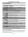
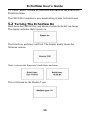
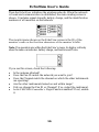
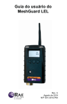
EchoView User’s Guide Rev. D August 2014 P/N F04-4001-000 EchoView User’s Guide © Copyright 2014 RAE Systems by Honeywell. 2 EchoView User’s Guide Contents 1 2 3 4 5 6 7 Warnings .................................................................................. 5 1.1 Operation Area and Conditions ................................. 7 1.1.1 Hazardous Areas classified by Zones ................. 7 1.1.2 Hazardous Areas classified by Divisions ............ 7 1.2 Instruction For Safe Use ............................................ 8 1.3 Use In Hazardous Areas............................................. 8 Standard Kit ............................................................................. 9 General Information ................................................................. 9 3.1 Key Features ............................................................ 10 Physical Description .............................................................. 11 4.1 LCD Display (Monitoring) ...................................... 12 4.2 LCD Display (In Alarm) .......................................... 12 4.3 Specifications ........................................................... 13 Operation................................................................................ 14 5.1 Enable The FMC2000 Controller’s EchoView Function ................................................................... 14 5.2 Turning The EchoView On ...................................... 15 5.3 Turning The EchoView Off ..................................... 17 5.4 Battery Charge Indicator .......................................... 17 5.5 Buzzer (Audible Alarm) Off Indicator .................... 18 5.6 Wireless Communication Indicator ......................... 18 Deploying The EchoView...................................................... 19 Programming The EchoView ................................................ 19 7.1 Settings ..................................................................... 21 7.1.1 Buzzer On/Off ................................................... 22 7.1.2 LCD Contrast .................................................... 22 7.1.3 Serial Number ................................................... 23 7.1.4 Firmware Version ............................................. 24 7.1.5 Factory Reset .................................................... 24 7.1.6 Edit Password.................................................... 25 7.1.7 Exit .................................................................... 26 7.2 Wireless.................................................................... 27 7.2.1 Ping Net ............................................................ 28 7.2.2 PAN ID Setup ................................................... 29 7.2.3 Join Net ............................................................. 30 3 EchoView User’s Guide 8 9 10 11 12 13 14 7.2.4 Channel Setup ................................................... 31 7.2.5 Exit .................................................................... 32 7.3 Viewing Monitors’ Data (Anytime)......................... 33 7.4 Backlight .................................................................. 33 Viewing Alarm Data .............................................................. 34 8.1 One Monitor In Alarm ............................................. 35 8.2 Multiple Monitors In Alarm..................................... 35 “Panic” Function .................................................................... 37 9.1 Enabling/Disabling The “Panic Button” Function ... 37 9.2 Using The “Panic” Function .................................... 39 9.2.1 Trigger All Relays............................................. 39 9.2.2 Trigger A Selected Relay .................................. 39 9.2.3 Clear Relays ...................................................... 40 Internal Battery Replacement ......................................... 41 10.1 Proper Battery Disposal ........................................... 42 Troubleshooting .............................................................. 43 EchoView Alarm Signal Summary.............................. 45 Appendix A: EchoView Installation ............................... 46 13.1 Magnet-Mount Installation ...................................... 46 13.2 Fixed Installation ..................................................... 47 13.3 Magnetic Mount Alternative Installation ................. 50 Appendix B: PowerPak External Battery Replacement.. 51 14.1 External Battery Usage ............................................ 51 14.2 External Battery Replacement Process .................... 54 4 EchoView User’s Guide 1 WARNINGS Read Before Operating This manual must be carefully read by all individuals who have or will have the responsibility of using, maintaining, or servicing this product. The product will perform as designed only if it is used, maintained, and serviced in accordance with the manufacturer’s instructions. Warning: Use only the Lithium battery or external rechargeable battery provided by RAE Systems. This instrument has not been tested in an explosive gas/air atmosphere having an oxygen concentration greater than 21%. Substitution of components may impair suitability for intrinsic safety. Replace batteries only in non-hazardous locations. STATIC HAZARD: Clean only with a damp cloth. For safety reasons this equipment must be operated and serviced by qualified personnel only. Read and understand instruction manual completely before operating or servicing. Any rapid up-scale reading followed by a declining or erratic reading may indicate a gas concentration beyond upper scale limit, which may be hazardous. 5 EchoView User’s Guide Marking The EchoView is certified according to the IECEx scheme, ATEX and CSA for US and Canada as protected by intrinsic safety. The product is marked with the following information: RAE SYSTEMS 3775 N. 1st. St., San Jose CA 95134, USA FMC-400 Serial No/barcode: XXX-XXXX-000 IECEx TSA 10.0016X Ex ia IIC T4 Ex ia I 0575 IM1/II 1G Class I, Gr. A,B,C,D Ex ia IIC T4 T4 Ex ia I Intrinsically Safe DNV 10 ATEX 83388X -40º C ≤ Tamb ≤ 50º C Warnings: Use only RAE 500-0111-000 for internal battery. Do not replace internal battery in hazardous locations. Ui: 3.6V; Ci: 78µF; Li/Ri: 3.5µH/ohm Understand User’s Manual before operating or servicing. Substitution of components may impair intrinsic safety. To prevent ignition of flammable or combustible atmospheres, disconnect power before servicing. 6 EchoView User’s Guide Applied Standards IECEx IEC 600790:2004 IEC 6007911:2006 ATEX EN 600790:2006 EN 6007911:2007 North America CAN/CSA-C22.2 No. 0-M91 CAN/CSA-C22.2 No. 15792 C22.2 No. 142-M1987 UL 913 UL916 Brazil Radio Specifications Radio model: RM2400A Frequency range: 2.400 to 2.4835GHz Modulation: 802.15.4 DSSS BPSK RF power(Tx): 20dBm Data rate: 250kbps 1.1 Operation Area and Conditions 1.1.1 Hazardous Areas classified by Zones EchoView is intended to be used in hazardous areas or mines susceptible to firedamp classified zone 0, zone 1 or zone 2, within the temperature range of -40º C to +50º C, where gases of explosion groups IIA, IIB or IIC and T4 may be present. 1.1.2 Hazardous Areas classified by Divisions EchoView is intended to be used in hazardous areas classified for Class I Div. 1 or 2, within the temperature range of -40º C to +50º C, where gases of explosion groups A, B, C or D and temperature class T4 may be present. 7 EchoView User’s Guide 1.2 Instruction For Safe Use Strictly follow the instructions for safe use. Application of the EchoView requires full understanding and strict observation of the instructions. 1.3 Use In Hazardous Areas Equipment which is intended for use in explosive atmospheres and which has been assessed and certified according to international regulations may be used only under specified conditions. The components may not be modified in any way. The appropriate regulations for service and repair must be properly observed during such activities. 8 EchoView User’s Guide 2 Standard Kit EchoView with antenna Maintenance tool User’s Guide 3 General Information The EchoView wirelessly receives the data shown on an FMC2000 controller in a MeshGuard network and displays them on its screen and delivers audible and visible alerts. The EchoView contains no sensors. Its built-in radio board operates on a frequency of 2.4GHz and complies with IEEE 802.15.4 standard. It works with the FMC2000 wireless controller on a flexible, robust wireless network to provide reliable, lowcost operation. Up to four EchoViews can operate on a single network. It also works in a ProRAE Guardian network with a PC. 9 EchoView User’s Guide 3.1 Key Features Up to 45 days continuous operation using external battery box IEEE 802.15.4 Mesh network functionality with 64-bit encryption Mesh network with auto network forming and configuration Operating distance: up to 300 m, line of sight Very low-cost installation − no hardwiring involved Large area coverage with multi-hop mesh network Field-replaceable battery Loud audio alarm, 90dB @ 30cm (12″) Easy-to-read continuous display of signal strength Bright red flashing alarm Highly resistant to RFI interference IP-65 rated for outdoor use in harsh environments 10 EchoView User’s Guide 4 Physical Description 6 1 2 5 3 4 1 2 3 4 5 6 LED alarm LCD (with backlighting) Buzzer alarm Battery cover (on bottom) Y/+, MODE, and N/- keys Antenna 11 EchoView User’s Guide 4.1 LCD Display (Monitoring) 4 1 5 2 6 3 1 2 3 4 5 6 7 7 Selected monitor (solid circle or star)* Unselected monitor (open circle or star) Offline monitor (open circle with “X”) Radio transmission indicator Audible alarm on/off indicator (“on” shown) Battery indicator Arrow indicating more than 8 instruments Note: The Unit ID can be a device ID as well as a radio ID, depending on the portable monitor’s setting. 4.2 LCD Display (In Alarm) 4 1 5 2 6 7 3 1 2 3 4 5 6 7 Monitor in alarm and selected (solid star) Unselected monitor in alarm (open star) Unselected monitor not in alarm (open circle) Radio transmission indicator Audible alarm on/off indicator (“on” shown) Battery indicator Arrow to go to the next “page” when more than 8 instruments are shown 12 EchoView User’s Guide 4.3 Specifications RF Certifications Display Audible alarm Visual alarm Calibration RF EM Immunity Operating Range Transmission Power Receiver Sensitivity User Interface Power Supply Max Current Consumption Operation Time Operating Temperature Humidity Dimensions Weight Package Mounting FCC Part15 CE EN 300328 SRRC(Pending) Customized LCD (1 x 1.5″) with backlight 90dB @ 30cm 2 super-bright red LEDs None necessary IEEE 802.15.4/Zigbee with mesh stack No effect when exposed to 0.43mW/cm2 RF interference (5-watt transmitter at 12") Up to 300 meters, line of sight Up to 18dBm (63mw EIRP) Minimum -95dBm at 2.4GHz Three keys (Y/+, MODE, N/-) D-size Lithium primary battery, +3.6V [email protected] during transmission <[email protected] during standby Internal Battery: Up to 10 days External Battery: Up to 45 days -40° to +50° C (-40° to 122° F) 0% to 95% relative humidity, non-condensing 26.5cm x 9.5cm x 5.5cm (10.5″ L x 3.7″ W x 2.1″ H) 0.6 kg (1.3 lbs) IP-65 Optional stainless-steel bracket mount or magnetic mount; wall mount for external battery FCC Part 15 Statement This device complies with Part 15 of the FCC rules. Operation is subject to the following two conditions: (1) This device may not cause harmful interference, and (2) this device must accept any interference received, including interference that may cause undesired operation. 13 EchoView User’s Guide 5 Operation The EchoView only operates in RTR (Router) mode. Therefore, when it is turned on, it is always operational. Whenever you start EchoView, it tries to rejoin the last network it was part of. Therefore, if the network is within range and if the channel and Pan ID have not changed, the EchoView should be able to rejoin the network without action on your part. Make sure the battery is installed before operating the EchoView. Refer to page 41 for information on battery installation and replacement. 5.1 Enable The FMC2000 Controller’s EchoView Function The EchoView can only receive data from an FMC2000 Controller if the controller is configured to broadcast data to it by enabling its EchoView Function. Therefore, you should perform this simple configuration before adding one or more EchoViews to a network. To enable the Pager function on the FMC2000 Controller: 1. Press the “MENU” key from Normal Operation Mode to enter the Configuration menu. 2. Provide a 4-digit password (the default value is 1234). 3. Press “Enter.” 4. The “General Settings” icon is highlighted. Press “Enter.” 5. Scroll to “Advanced Settings.” 6. Press “Enter.” 7. Input the advanced (6-digit) password. 8. Press Enter. 9. Input the 6-digit advanced password (the default is 123456). 10. Press Enter. 11. Scroll through the options until “EchoView” is highlighted. 12. Press “Enter.” 13. Select “All Alm” (all alarms) or “SNS Alarm” (sensor alarms, including High, Low, etc.) by using the up and down arrows. (There is also a “Disable” option that shuts off EchoView functionality.) 14 EchoView User’s Guide 14. Press “Enter” to lock in your selection and exit the EchoView Function menu. The FMC2000 Controller is now broadcasting its data for EchoViews. 5.2 Turning The EchoView On Hold down the [MODE] key and release it when the EchoView beeps. The display indicates that it is now on: The EchoView performs a self-test. The display briefly shows the firmware version: Next, it shows the firmware’s build date and time: This is followed by the Modem Type: 15 EchoView User’s Guide Then the EchoView initializes the wireless network. When the network is found and communication is established, the main reading screen is shown. It includes signal strength, battery charge, and the identification numbers of all monitors on the network: The monitor name shown on the EchoView screen is the ID of the monitor’s radio or the first four characters of the monitor’s radio. Note: If no monitors are within the EchoView’s range, its display will only show the radio-on indicator, battery charge, and buzzer on/off icon. If you see this screen, check the following: Is the antenna attached? Does the Pan ID match the network you want to join? Does the Channel match the channel on which the other instruments are operating? Are the other instruments turned on and within range? Did you change the Pan ID or Channel? If so, restart the instrument. Is the FMC2000 Controller’s Pager Function enabled? If not, enable it. 16 EchoView User’s Guide 5.3 Turning The EchoView Off Hold down the [MODE] key through the “5…4…3… 2… 1… Power Off” sequence. When you see “Power off!” release the [MODE] key. The EchoView is off when the display is blank. The EchoView is now off. 5.4 Battery Charge Indicator The EchoView’s internal battery is designed to provide power for up to 10 days. When the battery gets low, the EchoView beeps once per minute and the battery icon is empty. See page 41 for the replacement procedure. It is recommended that the battery be changed immediately, to minimize potential downtime. When the battery is almost completely depleted, the LCD displays “Power off,” and the LED and buzzer alarms activate once per second. The battery icon also blinks on and off. The low battery alarm continues until the battery runs out. Then the unit shuts down automatically. Battery power is indicated with an icon in the lower right corner of the screen, below the wireless communication indicator and buzzer icon: Battery Charge Indicator Battery charge is shown from empty to full: Empty Full 17 EchoView User’s Guide Note: For a fixed-system application, an external power source, the RAE PowerPak, can be used as a substitute for the internal battery. Only remove the external battery adapter in non-hazardous locations. 5.5 Buzzer (Audible Alarm) Off Indicator The EchoView’s buzzer (audible alarm) can be turned off, so the LED visible alarms flash but there is no sound when in alarm. The icon on the main screen indicates its state. Buzzer on Buzzer off 5.6 Wireless Communication Indicator The display employs an antenna icon to show wireless status. It is located in the upper right corner of the display: Signal Strength Indicator Signal strength is represented by vertical bars to the right of the antenna icon. The greater the number of bars to the right of the antenna icon, the better the connection quality. No signal Full strength Note: An “X” indicates no signal is detected. 18 EchoView User’s Guide 6 Deploying The EchoView When deploying a MeshGuard network that utilizes EchoViews, make sure the rest of the network has been set up before using an EchoView. The EchoView gets its information about the monitors on a network from the FMC2000 controller. It does not aggregate network data from all its nodes. Therefore, make sure the FMC2000 is operational and in communication with all monitors on the network, as well as with the EchoView. Before deploying an EchoView, it is important to have the Pan ID and Channel number on which the rest of the network is operating. Without these numbers to program into your EchoView, you cannot make it communicate with the network. 7 Programming The EchoView Programming Mode is accessed by first providing the correct password. Press and hold [MODE] and [N/-] until you see this screen: Input the 4-digit password: Increase the number from 0 through 9 by pressing [Y/+]. Decrease the number from 9 through 0 by pressing [N/-]. Step from digit to digit using [MODE]. 19 EchoView User’s Guide Once all the four digits have been entered, press [MODE] again to see the following screen appear. Press [Y/+] to enter the password. If you make a mistake, you can cycle through the digits by pressing [MODE] and then using [Y/+] and [N/-] to change the number in each position. Note: The default password is 0000. If your password is incorrect, you see this screen: After a few seconds, the EchoView exits to its main screen. When you have successfully entered Programming Mode, you see this screen: Note: If you do not make a selection in 60 seconds, the EchoView automatically exits to the main screen. Press [Y/+] or [N/-] to scroll to “Settings,” “Wireless,” or “Exit.” Then press [MODE] to select your choice. Settings provides information about your instrument. Some screens are readonly (you cannot edit them), but other screens allow you to change settings. Wireless consists of parameters you can set/change that affect wireless functionality, network configuration, etc. 20 EchoView User’s Guide 7.1 Settings Settings include some read-only information (Serial Number and Firmware Version) and some settings that you can change. Press [Y/+] to scroll up or [N/-] to scroll down. Note: Two more screens contain additional options: Note: The scrolling “wraps,” so once you reach the first or last item, it starts scrolling through the items again. Eight choices (including Exit) are available: Buzzer On/Off LCD Contrast Serial Number (read-only) Firmware Version (read-only) Factory Reset Edit Password Page Disable Exit To make a selection, scroll until the circle to the left of your choice is black, and then press [MODE]. Note: If you do not make a selection in 60 seconds, it automatically exits to the main screen. 21 EchoView User’s Guide 7.1.1 Buzzer On/Off You can turn the buzzer (audible alarm) on or off. To access the parameter, press [MODE] when its name is highlighted (dark circle): You are asked whether you want to disable (or enable, if it is already disabled) the audible alarm: or To toggle the audible alarm from on to off (or off to on), press [Y/+], and a confirmation message appears. To exit without performing the reset, press [N/-]. or 7.1.2 LCD Contrast The display’s contrast is adjustable via this menu. To access it, press [MODE] when its name is highlighted (dark circle): 22 EchoView User’s Guide The contrast value is shown in the display. Step through the digits from left to right by pressing [MODE]. Change a digit’s value by pressing [Y/+] to increase and [N/-] to decrease. After the third digit, you see a flashing “?” Save your changes by pressing [Y/+]. Exit without saving changes by pressing [N/-]. Step back to the first digit by pressing [MODE]. 7.1.3 Serial Number This shows the Serial Number of the EchoView. To view it, press [MODE] when “Serial Number” is highlighted (dark circle): The serial number is shown in the display: Press [MODE] to return to the Settings menu. If you do not make a selection in 60 seconds, the unit automatically exits to the menu. 23 EchoView User’s Guide 7.1.4 Firmware Version This shows the firmware version incorporated in the instrument. It is read-only. You cannot make changes to the information. To view it, press [MODE] when its name is highlighted (dark circle): Press [MODE] to return to the Settings menu. If you do not make a selection in 60 seconds, it automatically exits to the menu. 7.1.5 Factory Reset You can perform a factory reset to the instrument’s original settings. To access it, press [MODE] when its name is highlighted (dark circle): You are asked whether you want to perform the factory reset: To perform the reset, press [Y/+]. To exit without performing the reset, press [N/-]. 24 EchoView User’s Guide While the EchoView is being reset to its original factory settings, the screen shows that the activity is taking place: When the reset is complete, this screen appears: Then the unit returns to the Settings menu. Note: If you perform a factory reset, all of your settings are removed and cannot be retrieved. 7.1.6 Edit Password You can change the password by selecting “Edit Password.” At this screen, input your new password over the old one (or the default): Increase the number from 0 through 9 by pressing [Y/+]. Decrease the number from 9 through 0 by pressing [N/-]. Step from digit to digit using [MODE]. Note: If you make a mistake, you can cycle through the digits by pressing [MODE] and then using [Y/+] and [N/-] to change the number in each position. 25 EchoView User’s Guide Once all the four digits have been entered, press [MODE] again to see the following screen appear. Save your changes by pressing [Y/+]. Exit without saving changes by pressing [N/-]. Step back to the first digit by pressing [MODE]. Saving the password takes a moment, and a screen indicates that it has been successfully saved: 7.1.7 Exit Scroll until “Exit” is selected. Press [MODE] to return to the Programming Menu. Note: If you do not make a selection in 60 seconds, it automatically exits to the menu. 26 EchoView User’s Guide 7.2 Wireless Wireless consists of editable parameters and actions to configure, form, and test a closed-loop wireless network. Under Programming Menu, select “Wireless.” Press [Y/+] to scroll up or [N/-] to scroll down through wireless submenus. Note: When you reach the last item and continue scrolling, a second screen appears: The scrolling “wraps,” so once you reach the first or last item of either screen, it starts scrolling through the items in the other screen again. Five choices (including Exit) are available: Ping Net PANID Setup Join Net Channel Setup Exit To make a selection, scroll until the circle to the left of your choice is black, and then press [MODE]. Note: If you do not make a selection in 60 seconds, it automatically exits to the main Programming Menu. 27 EchoView User’s Guide 7.2.1 Ping Net Pinging tests the radio connection between the EchoView and other units on its network. (A “ping” is a short signal sent to the network to prompt a reply; it contains no other data.) Scroll until “Ping Net” is selected. Press [MODE] to ping the network. This message appears: Press [Y/+]. The Echoview broadcasts a ping signal to its network. All devices in the network that receive the ping signal respond with a beep if they are within the range. (The Echoview does not beep or flash its LED lights.) You can also ping from an instrument in the network. If it is within range, the EchoView responds with a beep and an LED light flash. If a network ping is unsuccessful, check the following: Is the antenna attached? Does the PAN ID match the PAN ID of other instruments in the network? Does the Channel match the channel on which the other instruments are operating? Are the other instruments turned on and within range? 28 EchoView User’s Guide 7.2.2 PAN ID Setup All units on a network must be programmed with the same PAN ID (Personal Network Identifier) to ensure communication compatibility. When you see this screen, press [MODE] to view the current PAN ID or to change it: Important! The allowed range for PAN ID numbers is 001 through 999. The screen shows the PAN ID, with the cursor blinking on the first digit. Step through the digits from left to right by pressing [MODE]. Change a digit’s value by pressing [Y/+] to increase and [N/-] to decrease. After the third digit, you see a flashing “?” Save your changes by pressing [Y/+]. Exit without saving changes by pressing [N/-]. Step back to the first digit by pressing [MODE]. Note: If you do not press a key within 60 seconds, the screen reverts to the programming Menu screen showing Settings, Modem, and Exit. 29 EchoView User’s Guide 7.2.3 Join Net This screen is for joining an existing network. When you see this screen, press [MODE] to join a network. This function allows the radio to scan all available channels and choose the least-congested one: The screen now displays a message asking if you want to confirm your choice to join a network: Press [Y/+] to join a network and automatically find the best channel to operate on. Press [N/-] to exit without joining a network. While the instrument starts joining a network, this message appears: Once the device has selected the least-congested channel and a network is joined, this message is displayed: 30 EchoView User’s Guide 7.2.4 Channel Setup All units in a network must operate on a single channel. The available channels vary by the internal wireless modem’s frequency, and channel ranges are set by RAE Systems to correspond with the wireless modem frequency. This is the modem frequency and its channel ranges: 2.4 GHz: Channels 11 through 26 Scroll until “Channel Setup” is selected. Press [MODE] to view or change the channel. The range of available channels is shown in parentheses. The screen also shows the channel number, with the cursor blinking on the first digit: Step from digit to digit from left to right by pressing [MODE]. Change a digit’s value by pressing [Y/+] to increase and [N/-] to decrease. When you press [MODE] you see a flashing “?” after the second digit: Save your changes by pressing [Y/+]. Exit without saving changes by pressing [N/-]. Step back to the first digit by pressing [MODE]. 31 EchoView User’s Guide If you have saved the channel number successfully, you see this screen: Important! Remember that the range of allowed channels for instruments on a EchoView’s network depends on the wireless modem frequency. Therefore, you may not be able to change the channel to a number outside of its assigned set of numbers. If you select an incompatible channel number, you will see this screen, and then the EchoView returns to the Wireless menu. 7.2.5 Exit To exit Wireless and return to the main Programming Menu, scroll until “Exit” is shown: With “Exit” selected, press [MODE]. The EchoView now returns to the Programming Menu screen. 32 EchoView User’s Guide 7.3 Viewing Monitors’ Data (Anytime) You can view the data from each monitor on the network, even if the monitor is not in alarm. To view the selected monitor’s data, select the monitor you want to view. Scroll up or down the list by using the [Y/+] and [N/-] keys. To make your selection, press [MODE]. The screen changes to show the data. For example: Monitor Identifier Alarm type Sensor Sensor reading Location This provides you with an overview, including The monitor’s location (if it has been programmed into the FMC2000 controller) The type of monitor The type of sensor The alarm state (NONE is shown when a monitor is not in alarm) The level or concentration of the substance being monitored (the unit depends on the type of sensor) To exit from this screen back to the main reading screen, press [MODE]. 7.4 Backlight Whenever you press the [Y/+] or [N/-] key while viewing the data, the backlight turns on for two seconds and then shuts off. 33 EchoView User’s Guide 8 Viewing Alarm Data Whenever the FMC2000 controller in a network receives alarm data from a monitor on the network, the EchoView also receives it. When monitoring the network and when no alarms are present, the EchoView’s display looks like this: All monitors are represented with a unique identifier and a circle. (A filled—dark—circle indicates the selected monitor for viewing, whereas an unfilled circle indicates the monitor’s presence on the network and no alarm.) To select a monitor: Press [Y/+] to scroll up or [N/-] to scroll down. Note: The scrolling “wraps,” so once you reach the top or bottom item, it starts scrolling through the items again. If there are more monitors than the display can show on one screen, it advances to the next screen. When the last monitor on that screen is reached, it “wraps” back to the first item on the initial screen. To make a selection: Scroll until the circle to the left of your choice is black, and then press [MODE]. Note: If you do not make a selection in 60 seconds, it automatically exits to the main reading screen. 34 EchoView User’s Guide 8.1 One Monitor In Alarm When a monitor on the network goes into alarm, the LEDs flash and the buzzer sounds. In addition, the circle to the left of the identifier changes to a five-sided star: Regardless of where the monitor’s identifier is in the list, when that monitor goes into alarm, its identifier goes to the beginning of the list and it is selected. 8.2 Multiple Monitors In Alarm If any other monitors on the network go into alarm while the one is already in alarm, the circle accompanying second monitor in alarm’s identifier also changes to a star. However, if the monitor is not the one currently selected, the star is unfilled: To view a monitor’s data: Scroll up or down through the list of monitors by pressing the [Y/+] or [N/-] key. As the selection advances down the list, each subsequent circle or star is filled (black). Note: Only one monitor can be selected for viewing at a time. 35 EchoView User’s Guide When the icon of the monitor you want to view is highlighted, then you can make your selection. Press [MODE]. The screen changes to show the data. For example: Monitor Identifier Alarm type Sensor Sensor reading Location This provides you with an overview of the alarm state, including The monitor’s location (if it has been programmed into the FMC2000 controller) The type of monitor The type of sensor The type of alarm state (HIGH alarm, LOW alarm, STEL, alarm, etc.) The level or concentration of the substance being monitored (the unit depends on the type of sensor) To exit from this screen back to the main reading screen, press [MODE]. 36 EchoView User’s Guide 9 “Panic” Function The EchoView has a “Panic” function, where you can manually trigger the relays at the main FMC2000 controller in the network. This must be configured in the EchoView in advance. This function allows you to trigger any individual relay or all relays simultaneously. 9.1 Enabling/Disabling The “Panic Button” Function Note: By default, the “Panic Button” feature is disabled. 1. Start the EchoView in Diagnostic mode by pressing and holding the [Y/+] and [MODE] keys simultaneously. 2. Once startup is completed and the main screen is shown, enter Programming mode by pressing and holding [MODE] and [N/-] simultaneously. 3. Provide the 4-digit password and press [Y/+] to enter it. Note: The default password is “0000.” This screen appears: 4. Press [N/-] until “Operating Mode” is highlighted. 5. Press [MODE] to select “Operating Mode.” “Panic Enable” or Panic Disable is highlighted. or 37 EchoView User’s Guide 6. Press [MODE] to make your selection. You are asked to confirm your selection. or 7. Press [Y/+] to save it or [N/-] to cancel any change. The change is registered, and you see the “success” screen: or After a few seconds, it returns to the menu screen with “Operating Mode” selected. Press [N/-] to advance to the screen with “Exit” highlighted. 8. Press [MODE] to exit to the main operating screen. 38 EchoView User’s Guide 9.2 Using The “Panic” Function The “Panic” function is designed so that it is very difficult to invoke by accident. Start at the normal operating mode screen: 1. From the normal operating mode screen, press and hold all three buttons until you see this screen: 2. Now press “Trigger Relays.” This screen is now shown: 9.2.1 Trigger All Relays With “All Relays” highlighted, press [MODE] to trigger all relays simultaneously. 9.2.2 Trigger A Selected Relay Scroll down the list of relays (1 through 5) by pressing [N/-]. Once you have highlighted the individual relay you want to trigger, press [MODE]. This triggers only that one selected relay. 39 EchoView User’s Guide Note: The relay on the FMC2000 controller remains triggered until it is cleared, either at the FMC2000 or at the EchoView. 9.2.3 Clear Relays Clear relays clears all of the relays on the controller, even if only one relay was triggered. Select “Clear Relays” and then press [MODE] to clear the relays. After clearing the relays, you can exit by using [N/-] to scroll down to “Exit.” Then press [MODE]. The main screen is shown. 40 EchoView User’s Guide 10 Internal Battery Replacement Battery compartment Sensor and battery removal tool (P/N 019-2044-000) 3-pin end Hexagonal end 1. Use the 3-pin end of the tool to unscrew and open the battery cover by turning it counterclockwise. 2. Remove the battery. 3. Insert the new battery with its positive (“+”) pole towards inside of the unit. 4. Replace the battery cover by turning it clockwise with the 3-pin end of the tool. 41 EchoView User’s Guide Note: Only Change battery in a safe location and use the battery RAE Systems provided. After changing the battery, wait at least 60 seconds before turning the EchoView on. Battery Battery cover Warning Only change internal battery in non-hazardous locations and use the battery RAE Systems provides (P/N: 500-0111-000), EVE ER34615 or XENO XL-205F). Only remove the external battery adapter in nonhazardous locations. 10.1 Proper Battery Disposal The Waste Electrical and Electronic Equipment (WEEE) directive (2002/96/EC) is intended to promote recycling of electrical and electronic equipment and their components at end of life. This symbol (crossed-out wheeled bin) indicates separate collection of waste electrical and electronic equipment in the EU countries. This product may contain one or more Nickel-metal hydride (NiMH), Lithium-ion, or Alkaline batteries. Specific battery information is given in this user guide. Batteries must be recycled or disposed of properly. At the end of its life, this product must undergo separate collection and recycling from general or household waste. Please use the return and collection system available in your country for the disposal of this product. 42 EchoView User’s Guide 11 Troubleshooting Failure Symptom Cannot turn on Cause Solution Battery charge too low Replace battery Battery has been changed Wait at least 60 seconds to turn on EchoView New battery needs to be discharged before use Check RAE Systems web site for information on batteries Controller cannot Communication not receive the EchoView’s established with the signal FMC2000. Enable Pager function on the FMC2000 (see page 14) Too much distance between the EchoView and the controller The distance should be 300 m, line of sight. Relocate EchoView(s) There is an obstruction between the EchoView and the controller. Relocate the EchoView or deploy more EchoViews Controller does not Press [Y/+] on the receive completed data detector to force it to packet send data packets Battery is low Replace battery EchoView and controller have different Pan ID numbers Set all units to the same Pan ID number 43 EchoView User’s Guide No Antenna Icon There is no reader or controller nearby. The controller or reader’s network has changed. Move the EchoView closer to a working controller or reader. Perform the network searching function in diagnostic mode. Move the EchoView The MeshGuard LEL is close to a working out of its RF range. controller or reader and Press [Y/+] Replace battery Battery is low Others Turn EchoView off and on again. Consult RAE Systems Customer Service. 44 EchoView User’s Guide 12 EchoView Alarm Signal Summary Alarm Mode Battery Low LCD Buzzer & LED 1 beep per minute 45 EchoView User’s Guide 13 Appendix A: EchoView Installation Two methods for mounting EchoView make it easy to install. The first method uses a magnet that screws onto the rear of the EchoView, making moving from one location to another easy. The second method uses a specially designed stainless-steel enclosure that is permanently mounted. It protects the EchoView from damage in industrial settings. 13.1 Magnet-Mount Installation Magnet For Mounting EchoView Rear of EchoView This magnet is powerful enough to support the EchoView when it is placed against a flat steel or iron surface. Important! Keep the magnet away from computer hard drives. The strong magnet can corrupt or erase data on these. 46 EchoView User’s Guide 13.2 Fixed Installation Four reinforced holes in the rear of the enclosure allow for a screw to pass through to the mounting brackets. Mounting Holes Side View Front View The enclosure can be mounted to a vertical or horizontal pole. Vertical pole Horizontal pole 47 EchoView User’s Guide Slip the screws through the two holes that are side by side in order to mount the enclosure to a vertical pole. Otherwise slip the screws through the two vertically aligned holes to attach the enclosure to a horizontal pole. Loosely assemble the clamp parts around the pole. Note that the screws have nuts that fit into the clamp parts. The clamp parts are designed to hole the nut so that you do not need to use a wrench. Hand-tighten the parts until snug. Tighten the hex screws from the front of the enclosure: Once the clamp parts and the enclosure are securely held against the pole, stop tightening. Note: The pole must be between 25mm (1″) and 63mm (2.5″) in diameter. 48 EchoView User’s Guide Next, place the EchoView into the enclosure: 1. 2. 3. 4. Lift up the hinged cover of the enclosure. Slide the EchoView into the enclosure from the top. Close the cover of the enclosure. Insert the hex screw into the cover’s locking portion, and tighten it. 5. The EchoView is now ready to use. 1 2 3 4 5 Note: The sensor cover on the bottom of the enclosure can be removed so that the filter and sensor can be inspected without removing the EchoView from the enclosure. Simply pull off the cover and follow the maintenance procedures in this guide. 49 EchoView User’s Guide 13.3 Magnetic Mount Alternative Installation The magnet-mount disc can be attached to the steel enclosure instead of the clamps. This approach provides the protection of the enclosure with the ease of installation afforded by the magnetic mounting. 1. Insert screw through magnetic disc. 2. Place the magnetic disc over the bottom hole on the rear of the enclosure. 3. Tighten the screw until the disc is snug. Side View Rear View 50 EchoView User’s Guide 14 Appendix B: PowerPak External Battery Replacement Warning: Only remove the external battery adapter in nonhazardous locations Note: For clarity, EchoView’s optional stainless-steel enclosure is not shown. Adapter Sensor and battery removal tool (P/N 019-2044-000) 3-pin end Hexagonal end 14.1 External Battery Usage An external battery unit, the RAE Systems RAE PowerPak, is used to power a EchoView in fixed installations or in situations where extended battery life is necessary. The connector from the external battery screws into the EchoView’s battery compartment. Bottom views of the EchoView in its steel enclosure are shown in the procedure below. 1. Remove battery cover with the 3-pin end of the sensor and battery removal tool by turning counterclockwise. 51 EchoView User’s Guide Power end of cable 2. Lift off the cover. 3. Insert the power end of the cable connected to the PowerPak. Cord to RAE PowerPak 4. Use the open hex end of the wrench, and with both pins mated with the two holes on the power end, tighten by turning clockwise until it is snug. Do not overtighten. Consult the RAE PowerPak User’s Guide for further connection and charging information. The EchoView is permanently mounted to a solid surface by first securing it in its steel enclosure (a screw through the back mates with the EchoView) and then securing the enclosure to a solid surface such as a wall or the metal mounting plate that holds both the EchoView and the RAE PowerPak. 52 EchoView User’s Guide Screw in rear of enclosure mates to rear of EchoView Front, side, and rear views of the steel enclosure show how the EchoView is secured for mounting. With the EchoView securely in its housing, you can remove the cover over the battery compartment so that you can place the connector from the RAE PowerPak into the EchoView. Use the sensor and battery removal tool as shown. Sensor and battery removal tool (P/N 019-2044-000) 53 EchoView User’s Guide 14.2 External Battery Replacement Process RAE PowerPak External battery replacement 1. 2. 3. 4. 5. 6. Unplug the battery connector. Loosen the safety screw holding the battery. Mount a new battery on the mounting bracket. Tighten the safety screw. Connect the EchoView to the battery. Switch on the EchoView. 54 EchoView User’s Guide Troubleshooting Failure Symptom Cannot turn on EchoView cannot receive the signal from the FMC2000 Controller Cause Solution Battery charge too low Replace battery Battery has been changed Wait at least 60 seconds to turn on EchoView New battery needs to be discharged before use Check RAE Systems web site for information on batteries Communication not established with the FMC2000. Enable Pager function on the FMC2000 (see page 14) Too much distance between the EchoView and the controller The distance should be 300 m, line of sight. Relocate EchoView(s) There is an obstruction between the EchoView and the controller. Relocate the EchoView or deploy more EchoViews Controller does not Press [Y/+] on the receive completed data detector to force it to packet send data packets Battery is low Replace battery EchoView and controller have different Pan ID numbers Set all units to the same Pan ID number 55 EchoView User’s Guide No Antenna Icon There is no reader or controller nearby. The controller or reader’s network has changed. The MeshGuard is out of its RF range. Move the EchoView closer to a working controller or reader. Perform the network searching function in diagnostic mode. Move the EchoView close to a working controller or reader and Press [Y/+] Replace battery Battery is low Others Turn EchoView off and on again. Consult RAE Systems Customer Service. 56 EchoView User’s Guide Ordering Replacement Parts: If you need replacement parts, a list is available online: http://www.raesystems.com Year Of Manufacture To identify the year of manufacture, refer to the serial number of the instrument. The letter in the serial number indicates the year of manufacture. For example, “M” indicates the manufacturing year is 2010. Letter J K M N P Q R S T U V W Year 2008 2009 2010 2011 2012 2013 2014 2015 2016 2017 2018 2019 57 EchoView User’s Guide 58 RAE Systems by Honeywell World Headquarters 3775 N. First St. San Jose, CA 95134-1708 USA Phone: 408.952.8200 Toll-Free: 888.723.4800 Fax: 408.952.8480 E-mail (sales support): [email protected] E-mail (technical support): [email protected] Web Site: www.raesystems.com RAE Systems Europe Kirstinehøj 23A, DK-2770 Kastrup • Denmark Tel: +45.8652.5155 • Fax: +45.8652.5177 RAE Systems (Hong Kong) Ltd. Units 1516-18, 15/F, Delta House, 3 On Yiu Street Shatin, N.T. Hong Kong Web: www.raesystems.cn • Email: [email protected] Phone: +852.2669.0828 RAE Systems Middle East LOB 7, Ground Floor, Office 19, Jebel Ali Free Zone Dubai, United Arab Emirates Email: [email protected] • Phone: +971.4.887.5562 Rev. D August 2014 P/N F04-4001-000