1
Man 243
Modem Logger
User Manual
Soil Instruments Limited has an ongoing policy of design review and reserves the right to amend these specifications without notice.
Man243 - Modem Logger - MN0814 - Rev1.0.0
1
What’s this manual about? This manual tells you about the 2 channel Modem Logger
and how to use it to take readings from an external 0-10V
sensor and an external pulse sensor.
Who does this apply to?
QUESTION
2
Installers, field engineers and technicians who need to
acquire readings from an external 0-10V sensor and a
pulse sensor.
Welcome!
Thank you for choosing the Soil Instruments Modem Logger.
This manual has been written to provide you with relevant
information and to guide you in the best practice for the use
and installation of a Modem Logger in order for you to get the
most out of our product.
Please read this manual thoroughly before use to help avoid
any problems and keep it handy when using a Modem Logger.
Modem Logger
The Modem logger is a highly advanced, rugged, low-power,
two channel datalogger, with one channel reading an
external 0-10V sensor and the other channel an external
pulse sensor.
The unit combines a high capacity datalogger with an on-board
GSM/GPRS Quad band modem. The logger runs on a single
D-Cell Lithium battery and is housed in a compact and robust
enclosure for reliable use in the field.
Readings are stored on a local SD card and are transmitted in
engineering units to any FTP site via the GSM/GPRS modem.
Logger settings are easily configured by the user, allowing full
control of settings and alarms, making the device completely
adaptable to site specific changes.
The Logger incorporates an intelligent ‘passive’ to ‘active’ alarm
system with up to six user defined prioritisation thresholds,
reducing battery consumption and overload of needless data.
With high capacity monitoring, automatic data transmission and
active multi layered alarming, the Modem Logger is an efficient,
cost effective solution to meet your monitoring requirements.
3
Contents
PART I – OVERVIEW6
Introduction:8
Important information8
Product8
Changes8
Warranty8
Disposal8
System Description9
Things You Need to Know about the Modem Logger
9
Features9
Benefits9
Applications9
System Details10
The Modem Logger10
System Components11
Quick Start Guide to Using the Modem Logger
12
Installing the Battery12
Connecting Via USB13
inserting the ‘GSM’ SIM Card
14
Setting Up the ‘GSM’ Connection
15
UK ‘GPRS’ Settings16
Updating Device Settings from FTP Server
17
PART II – DETAILED MODEM LOGGER USER GUIDE
18
Start-up of the Modem Logger
20
Power Supply20
USB Interface20
Getting Started21
‘Virtual COMport’21
Command Line Functions23
4
PART III – MODEM LOGGER CONFIGURATION & DATA FILES 24
Configuring the Modem Logger
26
Overview26
Command Interface26
Available Line Commands26
Settings File28
Structure of the ‘settings.ini’ File
28
PART IV – DETAILED SOFTWARE GUIDE
32
Performing Calculations on a Channel
34
Setting Alarms on a Channel
35
Calculations for Commonly Used Sensors
37
Updating Settings Via FTP 37
Methods of Updating Firmware
38
Commands Via SMS Text39
Using the Modem Logger as a Local Logger Only 39
PART V – CONNECTING SENSORS & INSTALLATION GUIDE
Connecting Sensors to the Modem Logger
Connecting a MEMS Piezometer and a Rain Gauge
Installing a Modem Logger in the Field
When You Are in the Field:
40
42
42
43
43
PART VI – APPENDICES44
Appendix A – Example of ‘settings.ini’ file
46
Appendix B – Frequently Asked Questions
49
5
Part I – Overview
6
Contents
This section contains the following topics.
TOPIC
Introduction:
Important information
Product
Changes
Warranty
Disposal
System Description
Things You Need to Know about the Modem Logger
Features
Benefits
Applications
System Details
The Modem Logger
System Components
Quick Start Guide to Using the Modem Logger
Installing the Battery
Connecting Via USB
Inserting the ‘GSM’ SIM Card
Setting up the ‘GSM’ Connection
UK ‘GPRS’ Settings
Updating Device Settings from FTP Server
SEE PAGE
8
8
8
8
8
8
9
9
9
9
9
10
10
11
12
12
13
14
15
16
17
7
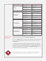
Introduction:
Important information
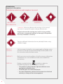
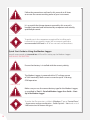
The following symbols are used throughout the manual
IMPORTANT
INFORMATION
QUESTION
WARNING
TIP
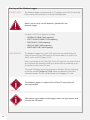
! Important: Failure to adhere to the warnings in this manual
may result in network disruption and possible data loss.
Failure to observe the warning may result in injury, product
malfunction, unexpected readings or damage to the product
that may invalidate its warranty.
WARNING
Tips give additional information that may be helpful when using
a Modem Logger.
TIP
PRODUCT
CHANGES
Soil Instruments Limited has an on-going policy of design review
and reserves the right to amend the design of their product and
this instruction manual without notice.
WARRANTY
Refer to our terms and conditions of sale for warranty information.
The batteries are a consumable item and are excluded from
the warranty.
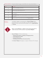
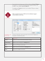
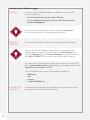
DISPOSAL
Products marked with the symbol are subject to
the following disposal rules in European countries:
• This product is designated for separate collection at an
appropriate collection point
• Do not dispose of as household waste
• For more information, contact Soil Instruments or the local
authority in charge of waste management.
WEE/DE3326WV
8
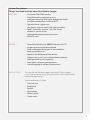
System Description
Things You Need to Know about the Modem Logger
FEATURES
• On-board GSM/GPRS modem
• Data delivered in engineering units
• Intelligent alarming with 6 user defined thresholds
and alarm notification via SMS and FTP
• Optional alarm suppression
• Low power; requires one D-Cell Lithium battery
• Reads 2 channels; channel 1 a 0-10V sensor,
channel 2 a pulse sensor
• Integrated barometric pressure sensor
• Micro SD card.
BENEFITS
• Data delivered direct to ‘ARGUS’ Software via FTP
• No post-processing of data required
• Swift notification of changes in site conditions,
alerting multiple users
• Reduces the likelihood of false alarms
• Operates for up to 2 years without battery change
• Intelligent dual sensor capability
• Atmospheric pressure compensation
• Internal logging of millions of data points.
APPLICATIONS
The two channel Modem Logger reads one 0-10V analogue
sensor and one pulse sensor for geotechnical and environmental
monitoring applications.
Typical applications include:
• Pore pressure
• Water level
• Rainfall
• Wind speed
• Motor control
• Pump status.
9
System Details
THE MODEM
LOGGER
The Modem Logger is a high capacity two channel datalogger with an
on-board GSM/GPRS Quad band modem. The logger incorporates a
barometric sensor, allowing for barometric pressure compensation and
will work with any M2M (machine2machine) SIM card as it is not locked
to a specific network.
The logger has two sensor input channels; one analogue signal channel
and one pulse sensor channel.
The Modem Logger contains a mini USB connector; the USB interface
will mount both as a Flash Drive (MSC) and a serial COM port (CDC).
When connected to a PC, the Flash Drive will mount as an external hard
drive without the need for a software driver, allowing access to the files
on the micro SD card.
The serial COM port can be mounted on a Windows PC by installing the
driver supplied on the SD card.
The Logger can either be programmed manually using a laptop with
a USB cable, or remotely via the FTP server using an editable settings
file from which reading, logging and uploading parameters are set
and calibration factors and alarms defined.
The alarm system, SMS functions, reading intervals and schedules can
be programmed or changed at any time quickly and efficiently via the
FTP site. The data can then be viewed by anyone at any time; all that
is required is an internet connection and the log on details for the
FTP server.
The multi layered ‘passive’ to ‘active’ alarm system incorporates up to six
user defined prioritisation thresholds. Once setup, the Logger remains in
‘passive’ mode logging at user defined intervals, until any of the pre-set
alarm levels are breached, at which point it will automatically switch to
‘active’ mode and initiate increased data logging and transfer to the
FTP site whilst simultaneously sending out multi-level SMS text alerts
to multiple contacts.
The readings are automatically transferred to the FTP site in engineering
units, so data can be directly imported into ‘ARGUS’ Monitoring Software.
10
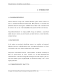
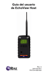
System Components
USB protective cap
SIM card holder
GPRS Modem
Logger board
Sensor terminal panel
Battery compartment
Mounting plate
Sensor cable gland
Barometric compensation vent
11
Follow the precautions outlined in this manual at all times
to ensure the correct working order of your instrument.
WARNING
It is essential that the equipment covered by this manual is
handled, operated and maintained by competent and suitably
qualified personnel.
IMPORTANT
INFORMATION
To guide you in the competence required for installing each
instrument in our product range, Soil Instruments provides a
recommended skill level in all of our manuals and datasheets.
TIP
Quick Start Guide to Using the Modem Logger
itmsoil recommend an intermediate skill level for setting up the Modem Logger
INSTALLING THE BATTERY
Ensure that battery is installed with the correct polarity.
WARNING
The Modem Logger is powered with a DC voltage source
of 3.6V nominally. Peak current use can be up to 1A during
GSM operation.
IMPORTANT
INFORMATION
Make sure you use the correct battery type for the Modem Logger,
as specified in ‘Part II – Detailed Modem Logger User Guide – StartUp of the Modem Logger’
WARNING
To make the file extensions visible in ‘Windows 7’, go to ‘Control Panel
– Appearance and personalization – Folder Options – View’ and un-tick
‘Hide extensions for known file types’.
TIP
12
STEP
1
ACTION
Insert the battery in the holder with the positive (+) pole oriented as
indicated in picture below. Push in firmly.
Positive (+) pole
Negative (-) pole
CONNECTING
VIA USB
STEP
The Modem Logger has a mini USB connector mounted within the
external housing. The USB interface will mount both as a Flash Drive
(MSC) and a serial COM port (CDC).
ACTION
1
Remove the protective cap located at the top of the Modem Logger
to access the USB connection as shown in the pictures below.
2
Using the USB cable supplied with the logger, connect the mini USB
plug to the to the mini USB connector.
3
Connect the other end to your PC.
4
The device should automatically mount as a USB disk drive. The SD card
mounted as a disk drive will contain the following files and folders:
• ‘Settings.ini’ file contains all the devices settings for
measurements, logging, modem and alarming.
• ‘.log’ files contains the latest measurements and alarms
• ‘Log’ and ‘back-up’ folders with historic measurement data.
Please refer to ‘Part II - Detailed Modem Logger User Guide - Start-up of
the Modem Logger ’ in this manual for more details.
5
The device will also attempt to mount as a ‘Virtual COMport’ (CDC serial bus). This allows direct interfacing to the device using a common
terminal program, such as ‘HyperTerminal’ or ‘Termite’.
The ‘Virtual COMport’ will appear as a regular COM port in PC manager.
Please refer to ‘Part II - Detailed Modem Logger User Guide - Start-up of
the Modem Logger ’ in this manual for more details.
13
INSERTING THE
‘GSM’ SIM CARD
The GSM module has an onboard holder for a standard size SIM card.
Avoid touching the surface of the PCB when inserting the SIM
to avoid damaging the component. If possible ground yourself
before inserting the SIM.
WARNING
Make sure that the SIM card is suitable for GPRS data
transmission privileges. If you are unsure, check with
your mobile operator provider.
WARNING
STEP
14
ACTION
1
Slide to unlock the holder and hinge upwards as shown in the
picture below.
Slide to unlock
Lift to open
2
Slide the SIM card into the guidance rail.
3
Push down and slide back to lock.
SETTING UP
THE ‘GSM’
CONNECTION
The following settings may need to be modified to the ‘settings.ini’
file in order for your mobile operator to initiate a GSM connection
for SMS messaging;
If authentication is needed on the network you need to modify the
following lines;
[gsm]cmd=AT+CPIN=xxxx, default is ‘0000’ please check with SIM
card provider if different.
[gsm]apn=yourapn
[gsm]login=yournetworkusername
[gsm]password=yournetworkpassword
Please refer to ‘Part I - Overview - UK ‘GPRS’ Settings ’ in this manual for
more details.
The modem is set to ‘pap’ authentication as standard. To change to
‘chap’ authentication, add the following line to the ‘settings.ini’ file;
[gsm]cmd=AT#GAUTH=2
(0=none, 1=pap, 2=chap)
If you have made any changes to the ‘settings.ini’ file, you can force
the device to load the updated settings using either of the following
two options;
• Type the command ‘readsettings’ and click ‘<ENTER>’ in the
command line of the terminal application (‘HyperTerminal’
or ‘Termite’) connected to the ‘VirtualCOM’ port.
• Unplug the battery from the Modem Logger board, wait for 1
minute and re-connect.
15
UK ‘GPRS’
SETTINGS
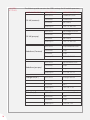
The following table contains the GPRS settings for UK mobile operators;
MOBILE OPERATOR
O2 UK (contract)
O2 UK (pre-pay)
Vodafone (Contract)
Vodafone (pre-pay)
Orange UK (EE )
T-Mobile (all)
16
GPRS SETTINGS
OPERATOR SETTINGS
GPRS APN:
mobile.o2.co.uk
Username:
mobileweb
Password:
password
Gateway IP:
193.113.200.195
GPRS APN:
payandgo.o2.co.uk
Username:
payandgo
Password:
password
Gateway IP:
193.113.200.195
GPRS APN:
wap.vodafone.co.uk
Username:
wap
Password:
wap
Gateway IP:
212.183.137.12
GPRS APN:
pp.vodafone.co.uk
Username:
wap
Password:
wap
Gateway IP:
212.183.137.12
GPRS APN:
orangeinternet
Username:
user
Password:
pass
Gateway IP:
192.168.71.35
GPRS APN:
general.t-mobile.uk
Username:
user
Password:
wap
Gateway IP:
149.254.1.10
MOBILE OPERATOR
Three
BT Mobile
Tesco Mobile
Virgin Mobile
GPRS SETTINGS
OPERATOR SETTINGS
GPRS APN:
three.co.uk
Username:
guest
Password:
guest
GPRS APN:
btmobile.bt.com
Username:
bt
Password:
bt
Gateway IP:
212.183.137.12
GPRS APN:
prepay.tesco-mobile.
com
Username:
tescowap
Password:
password
Gateway IP:
193.113.200.195
GPRS APN:
goto.virginmobile.uk
Username:
user
Password:
{blank}
Gateway IP:
193.30.166.3
UPDATING DEVICE The device settings for the logger can be modified via the FTP site using
SETTINGS FROM
a text file with the file name; ‘<unitname>-settings.new’.
FTP SERVER
This file is a ‘delta-list’, which means it only needs to contain the settings
that you want to be added or changed; it does not need to be a full
‘settings.ini’ file.
The settings will be retrieved by the logger during the next connection
to the FTP site. An acknowledgement file with the extension ‘.ack’ will
be placed on the FTP server from the device to confirm that the settings
have been updated. Please refer to ‘Part II – Detailed Tilt Logger’ user
Guide in this manual for more details.
The new file for the FTP site, must have ‘.new’ extension as the logger
will download this file and replace it on the SD card as a ‘.ini’ file.
TIP
17
Part II – Detailed
Modem Logger
User Guide
18
Contents
This section contains the following topics.
TOPIC
Start-up of the Modem Logger
Power Supply
USB Interface
Getting Started
‘Virtual COMport’
Command Line Functions
SEE PAGE
20
20
20
21
21
23
19
Start-up of the Modem Logger
POWER SUPPLY
The Modem Logger is powered with a DC voltage source of 3.6V nominally.
Peak current use can be up to 1A during GSM operation.
Make sure you only use the batteries specified for the
Modem Logger.
WARNING
Suitable Li-SOCl2 3.6V batteries include;
•
•
•
•
•
USB INTERFACE
TADIRAN TL-5930 (19Ah capacity)
SAFT LSH20 LG 33600 (17Ah capacity)
EVE ER34615 (19Ah capacity)
XENO XL-205F (19Ah capacity)
VARTA ERD7120 (19Ah capacity)
The Modem Logger has a mini USB connector mounted within the
external housing. The USB interface will mount both as a Flash Drive
(MSC) and a serial COM port (CDC).
When connected to a PC, the Flash Drive will mount as an external hard
drive without the need for installing a software driver, enabling access
to the files on the micro SD card.
The serial COM port can be mounted on a Windows PC by navigating
to the file named ‘TinySense_V2.inf’ when prompted for the driver
software location. This file can be found on the loggers SD card.
The Modem Logger is supplied with a Micro SD containing all
the required files.
IMPORTANT
INFORMATION
After power up or reboot of the logger, make sure you remove and
reinsert the USB cable.
IMPORTANT
INFORMATION
20
GETTING STARTED To get the Modem Logger started, follow the steps outlined below;
STEP
ACTION
1
Connect the battery (3.6V DC).
2
Connect the USB interface to a PC.
3
A green LED will start blinking at regular intervals; 3 seconds off,
1 second on.
4
Follow the prompts, selecting the option to locate the driver manually
on your PC.
5
Browse to the SD Card and select the file ‘TinySenseV2.inf’.
‘VIRTUAL
COMPORT’
The Modem Logger can be mounted as a ‘Virtual COMport’ when
connecting to a PC via the USB cable. This allows direct interfacing to
the device using a common terminal program, such as ‘HyperTerminal’
or ‘Termite’.
Make sure that ‘Debug=1’ in ‘[main]’ section of the settings file to
enable interaction with the device using ‘Virtual COMport’.
IMPORTANT
INFORMATION
‘Virtual COMport’ will allow the following;
• Viewing measurement sampling and logging activity
• Viewing debug messages
• Viewing GSM activity
• Entering commands from the command line
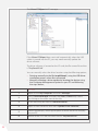
The ‘Virtual COMport’ will appear as a regular COM port in PC manager.
21
The ‘Virtual COMport’ in PC manager.
If the ‘Virtual COMport’ does not install automatically when the USB
cable is inserted into the PC, you may need manually update the
driver software.
The driver software is located on the SD card; the file name of the driver
is ‘TinySenseV2.inf’.
You can manually select the driver location using the following options;
• Pointing manually to the file ‘msp430tools’, using the USB driver
installation process when first connected
• Manually initiating a driver update by locating the device using
the ‘Computer Management’ option on your PC and following
the steps below;
STEP
22
ACTION
1
Right click on ‘My Computer’ and select ‘Manager’.
2
Select ‘Device Manager’ and open the ‘Ports (COM & LPT)’ menu
by clicking on the arrow next to the title.
3
It will most likely be listed as ‘unknown device’.
4
Right click on the device and select ‘Update Driver Software...’.
5
Follow the prompts, selecting the option to locate the driver manually
on your PC.
6
Browse to the SD Card and select the file ‘TinySenseV2.inf’.
Once the device has been successfully installed, the ‘Virtual COMport’
will appear as a standard COM port with an assigned number in PC
Manager in the category ‘Ports (COM&LPT)’.
The application ‘Termite’ will also list all available COM port numbers
in its settings menu.
Make sure that the correct COM Port for the Modem Logger is
selected before continuing.
IMPORTANT
INFORMATION
COMMAND LINE
FUNCTIONS
The most commonly used commands on the ‘Virtual COMport’ are
displayed in the following table;
COMMAND
FUNCTION
‘status’
Displays the status of the measurement channels.
‘readsettings’
Reads the new settings of a ‘settings.ini’ file.
‘FTP’
Forces an FTP data transmission.
‘reset’
Restarts the unit and reads the ‘settings.ini’ file.
‘help’
Displays all available commands.
23
Part III –
Modem Logger
Configuration &
Data Files
24
Contents
This section contains the following topics.
TOPIC
Configuring the Modem Logger
Overview
Command Interface
Available Line Commands
Settings File
Structure of the ‘settings.ini’ File
SEE PAGE
26
26
26
26
28
28
25
Configuring the Modem Logger
OVERVIEW
To interact with the Modem Logger and define user settings the
device incorporates;
• A command interface via the serial COM port
• A user editable text file (plain ASCII) on the SD card with the
file name ‘settings.ini’.
Soil Instruments recommends using the text editor ‘NotePad++’
as it will display the lines in a more organised fashion.
TIP
COMMAND
INTERFACE
The command interface is directly accessed through the COM port.
You can look up the COM port number that was assigned to the
Modem Logger on your PC by right clicking on ‘My Computer’ and
selecting ‘Manager’. Select the ‘Device Manager’ and expand the tree
with ‘Ports (COM&LPT)’. You can now see the available COM ports.
TIP
Any serial terminal program will enable you to interface with the COM
port in ‘command line mode’. Suitable open source applications include
‘HyperTerminal’, ‘Termite’ or ‘PuTTY’.
The standard Baudrate settings for the Modem Logger are;
•
•
•
•
AVAILABLE LINE
COMMANDS
26
9600 baud
8 bit
no parity
1 stop bit (9600 8-N-1)
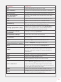
The following table displays the available line commands with a brief
description of each command line function;
COMMAND
FUNCTION
‘dir’
Show the directory list on the SD card
‘del <filename>’
Delete the file named within the brackets <filename>
‘cd <directory>’
Go to directory named within the brackets <directory>
‘ren <old filename>
<new filename>’
Rename a file named within the brackets from <old>
to <new>
‘info’
Shows hardware info about the unit and the SD Card
‘ver?’
Shows current version of the installed firmware
‘readsettings’
Forces a reading of the ‘settings.ini’ file from the
SD card and stores it in the on-board memory
‘setting <groupname> [help]’
Request the settings, optionally with ‘groupname’ to
reduce the length of the list. When adding ‘help’ as a
parameter it will show the required syntax
‘[groupname]<setting>
=parameter’
Changes a setting to ‘parameter’
‘[groupname]<setting>?’
Shows the current value of this setting
‘savesettings’
Stores current settings in the ‘settings.ini’ file on
the SD Card
‘FTP’
Manually triggers transmission of files via FTP
‘alive < optional smsnumber>
<optional wait time in seconds>’
Sends a ‘keep-alive’ message via SMS text
‘reset’
Restarts the unit and reads the ‘settings.ini’ file
‘status’
Shows status and current measurement values of
all channels. Also provides info on the GSM telecom
provider and signal strength (if communication has
taken place)
‘help’
Provides a short list of selected commands
‘bat?’
Shows the supply voltage in Volts
‘baro?’
Shows barometric air pressure value in mbar
‘time <date/time>’
Sets the internal clock.
Syntax; ‘dd-mm-yyyy hh:mm:ss’ Typically only done
when not using the GSM modem. The GSM modem
will sync the time and date of the unit with an external
server upon each connection event
‘time?’
Shows the current time and date setting of the unit
‘tgsm’
Enables direct AT command communication with
the GSM module (for debugging only)
27
Settings File
All the settings for the Modem Logger are stored in and retrieved from
the ‘settings.ini’ file which is located in the root directory of the SD card.
The ‘settings.ini’ file must remain in the root directory of the
SD card.
WARNING
This file can be directly edited via the mounted Flash Drive of the
Modem Logger.
STRUCTURE OF THE ‘SETTINGS.INI’ FILE
Definitions in the ‘settings.ini’ file are divided into several groups;
COMMAND
FUNCTION
‘[main]‘
General device settings
‘[gsm]‘
GSM modem settings
‘[FTP]‘
Settings for the FTP client
‘[sms]‘
List of telephone numbers to receive SMS text messages
‘(for alarms and status updates)‘
Shows hardware info about the unit and the SD Card
‘[channel_1/2/3/5]‘
Measurement channel settings
‘channel_1‘
Main sensor channel, 0-10V
‘channel_2‘
Pulse sensor
‘channel_3‘
On-board barometer
‘channel_5‘
Supply (battery) voltage
‘[main]‘
28
‘name=<name>’
Device name <max 18 characters >
‘enable=<0/1>’
Device is active (1), or inactive(0)
‘keepalivetime=hh:mm’
Time of day for sending a ‘keepalive’ message
‘keepaliveinterval=x’
Interval for sending a ‘keepalive’ message (0-255) in days
‘keepalivesms=n’
SMS number index to which ‘keepalive’ message is sent
‘header_1= <text>’
Header line in log file (= data file) <max 10 characters>
‘header_2= <text>’
Second header line in log file <max 43 characters>
‘[main]’
‘logseparator=<ascii value>’
Separator between timestamp and measurement
value (59 = semicolon)
‘excvolt=<0,1,2,3>’
Programmable sensor excitation voltage (on channel_1)
1=12V, 2=15V, 3=24V
‘events=<0/1>’
Enable (1) / Disable (0) logging of events (in ‘events.txt’)
‘debug=<0/1>’
Enable (1) / Disable (0) debug messages on COM port
‘buttonstatus=x’
Sets the actions initiated by pressing the ‘attention’ button
‘buttonstatus=1’
Read ‘settings.ini’ file
‘buttonstatus=2’
Measure, store and FTP session
‘buttonstatus=4’
Send SMS text to ‘<sms_index>’ including measurement
values of all channels
Values of ‘buttonstatus=7’ status can be summed to
enable multiple functions, for example;
• buttonstatus=3 performs operations 1 and 2
• buttonstatus=7 performs all of the above functions
‘buttonsms=<sms_index>’
SMS number from SMS list for reception of ‘attention
button SMS’
‘[gsm]’
‘debug=<0/1>’
Enable (1) / Disable (0) debug messages of GSM module
‘smsrecv=<0/1>’
Enable (1) / Disable (0) reception of SMS messages
‘cmd=<cmd>’
Program an extra GSM command (AT protocol)
(e.g. pincode AT+CPIN1234 )
‘gsmontime=<x>’
Time in seconds that the GSM stays active after FTP
transmission in order to check for incoming SMS messages
‘apn=<text >’
Mobile network operators Access Point Name for GPRS
access (max 24 characters)
‘login=<text >’
Optional GPRS login username (max 24 characters)
‘password=<text >’
Optional GPRS login password (max 24 characters)
‘daytimeserver=<url>’
URL address of a daytime server for time synchronization
‘utc=<correction>’
Optional correction of unit time w.r.t. UTC (in hours)
29
‘[FTP]’
‘server=<server address>’
Server address (URL) of the FTP data server (max 22 chars)
‘path=<remote path>’
Directory on the FTP server (max 18 chars, start with ‘/’)
Note: using this option may increase length of FTP session
‘login=<password>’
FTP login name (max 18 chars)
‘password=<password>’
FTP password (max 18 chars)
‘time=<hh:mm>’
Absolute time (on day, 24hr notation) for FTP transmission
‘interval=<interval>’
Interval for FTP transmission (days)
‘time= hour’
FTP transmission on the whole hour
‘time=work’
FTP transmission on the whole hour between 7 am and 4 pm
‘time=min’
FTP transmission on the whole minute
‘interval=<interval>’
Interval for FTP transmission (in hours or minutes) depending
on the mode
‘passive=<0/1>’
Passive(1) of active (0) connection type to FTP server
(typically passive)
‘nobackup=<0/1>’
Turn of creation of backup files (1) or leave on (0 = default)
‘getsettings=<0/1>’
Get ‘settings.ini’ file updates from FTP server (1 = default)
‘getfirmware=<0/1>’
Get new firmware from FTP server (0 = default)
‘sendsettings=<0/1>’
30
Units current ‘settings.ini’ file will be put on the FTP server;
Filename: ‘<unitnaam>-set-yyyymmddhhmmss.ini’;
the ‘Timestamp’ in the filename is the date the file was
changed on the SD card. File transfer only if not present on
FTP server. This way only a changed ‘settings.ini’ file will be
placed on the FTP server upon next transmission
‘[sms]’
‘sms_1=<sms number 1>’
SMS number 1 including country code (e.g. 44123456789)
‘sms_2=<sms number 2>’
SMS number 2 including country code
‘sms_3=<sms number 3>’
SMS number 3 including country code
‘sms_4=<sms number 4>’
SMS number 4 including country code
‘sms_5=<sms number 5>’
SMS number 5 including country code
‘sms_6=<sms number 6>’
SMS number 6 including country code
‘sms_7=<sms number 7>’
SMS number 7 including country code
‘sms_8=<sms number 8>’
SMS number 8 including country code
‘sms_9=<sms number 9>’
SMS number 9 including country code
‘[channel_1/2/3/5]’
‘channel_1’
Measurement channel settings
Main sensor channel, 0-10V
‘channel_2’
Pulse sensor
‘channel_3’
On-board barometer
‘channel_5’
Supply (battery) voltage
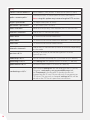
‘name=<channel name>’
‘tagname=<tagname>’
‘enable= <0/1>’
‘inputtype=<0/1/2/3>’
‘measuretime=<msec>’
‘measureinterval=
<interval>’
‘logtime=<tijd>’
Name of this channel (appears in data file name)
(max. 13 chars)
Optional tag that can be added to each data line
(max 31 chars)
Turn channel on (1) or off (0)
Sensor input type (1 = pulse, 2 = 0-10V)
Voltage excitation time of sensor (in millisecond)
before taking reading
Sampling interval in seconds (when not in alarm zone),
not stored
Logging interval in seconds (when not in alarm zone),
data stored
‘validlow=<value>’
Lower limit for validation of data GOOD/BAD in log
‘validhigh=<value>’
Higher limit for validation of data GOOD/BAD in log
‘units=<text>’
Units of output data, e.g. ‘Volt’ or ‘mBar’, appears in
alarm messages
‘logging=(0/1)’
Turn logging of data to SD Card on (1= default) or off (0)
‘precisionlog=<0,1,2,3,4>’
Number of decimal points when storing measurement values
31
Part IV – Detailed
Software Guide
32
Contents
This section contains the following topics.
TOPIC
Performing Calculations on a Channel
Setting Alarms on a Channel
Calculations for Commonly Used Sensors
Updating Settings Via FTP
Methods of Updating Firmware
Commands Via SMS Text
Using the Modem Logger as a Local Logger Only
SEE PAGE
34
35
37
37
38
39
39
33
PERFORMING CALCULATIONS ON A CHANNEL
The following describes the functions required for performing calculations
on a sensor channel.
‘calc=<calc string>’ Calculation string performed on sensor value in order of declaration. Operations are declared separated by comma’s (e.g. *8,-0.1,^1). Max total string length is
63 characters.
Available operators are defined in the following table;
OPERATOR
FUNCTION
‘+’
Add
‘-’
Subtract
‘*’
Multiply
‘/’
Divide
‘^’
Power
‘=’
Set equal to
‘b’
Barometer value
‘c<n>’
Value of channel <n>
‘sin, cos, tan’
Sine, cosine, tangent. Input values in degrees
‘asin, acos, atan’
Reverse sine, cosine, tangent. Output values in degrees
‘log’
Natural logarithm (base e)
‘log10’
Standard logarithm (base 10)
‘sqrt’
Square root
‘pcalc’
2nd order polynomial (abc-equation)
To include a second order polynomial calibration function (typical for
piezometers) you will need set the following parameters;
‘[channel_1]piezocalc=a:b:c’ declare the a-b-c calibration constants (for piezometer)
‘[channel_1]calc=pcalc’
calculation is: c + (b x input value) + (a x (input value²))
pcalc in the calc string can still be preceded or followed by other operations.
34
Example 1;
‘[channel_1]calc=/10,+0.003,*1000’
=((value/10)=0.0030*1000
Example 2;
‘[channel_1]calc=pcalc,-1.2’
=(piezocalc)-1.2
When declaring a calc string, the result of the calculation
replaces the sensor output signal (in V) for all other operations;
logging, checking against alarm thresholds and checking against
validation limits.
WARNING
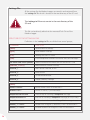
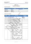
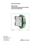
SETTING ALARMS Mulit-layered alarms and SMS text functions can be setup on each channel
ON A CHANNEL
according to your requirements. These are explained in the following
diagram and table;
All settings are preceded by ‘[channel_n]’ for the channel to which
the alarming applies. For example ‘[channel_1]l_limit1=-8.5’.
IMPORTANT
INFORMATION
Alarm Zone (A3)
h_limit3
Warning Zone (A2)
h_limit2
Alarm Activation Delay
Measuring
Transmitting on Alarm Activation by Limits
Global:
Alarmacttime,
Alarmclrtime
(checked for each
limit crossed)
Sample_A3, Log_A3
Ftppush_A3=0/1, ftpint_A3, ftptime_A3,
smspush_A3=0/1, sms_text_A3=” ”,
smslist_A3=<index>
Sample_A2, Log_A2
Ftppush_A2=0/1, ftpint_A2, ftptime_A2,
smspush_A2=0/1, sms_text_A2=” ”,
smslist_A2=<index>
Sample_A1, Log_A1
Ftppush_A1=0/1, ftpint_A1, ftptime_A1,
smspush_A1=0/1, sms_text_A1=” ”,
smslist_A1=<index>
Measureinterval,
Logtime
Global:
[ftp]interval, [ftp]time
Sample_A1, Log_A1
Ftppush_A1=0/1, ftpint_A1, ftptime_A1,
smspush_A1=0/1, sms_text_A1=” ”,
smslist_A1=<index>
Sample_A2, Log_A2
Ftppush_A2=0/1, ftpint_A2, ftptime_A2,
smspush_A2=0/1, sms_text_A2=” ”,
smslist_A2=<index>
Sample_A3, Log_A3
Ftppush_A3=0/1, ftpint_A3, ftptime_A3,
smspush_A3=0/1, sms_text_A3=” ”,
smslist_A3=<index>
Alert Zone (A1)
h_limit1
Normal Zone
Or activation by
number consecutive
samples above limits:
Alarmact=n
Alarmclr=m
l_limit1
Alert Zone (A1)
l_limit2
Warning Zone (A2)
l_limit3
Alarm Zone (A3)
35
Referring to the preceding alarm scheme;
COMMAND
FUNCTION
‘l_limit<n>=xx’
Sets value of lower limit l_limit<n> (1,2,3)
‘h_limit<n>=xx’
Sets value of higher limit h_limit<n>(1,2,3)
‘l_limit<n>on=0/1’
Enables (1) / Disables (0) l_limit<n>
Default=0 when not declared
‘h_limit<n>on=0/1’
Enables (1) / Disables (0) h_limit<n>
Default=0 when not declared
‘alarmacttime=xx’
Sets time in seconds that measurement value needs
to be in an alarm zone before the alarming is activated
‘alarmclrtime=xx’
Sets time in seconds that measurement value needs to
be in the normal zone before the alarming is deactivated
‘alarmact=xx’
Sets the number of consecutive samples with a value
in an alarm zone before the alarming is activated
‘alarmclr=xx’
Sets the number of consecutive samples with a value
in the normal zone before the alarming is deactivated
‘sample_a< n>=xx’
Sampling interval in seconds while in zone <n>
‘log_a<n>=xx’
Log (=data storage) interval in seconds while in zone <n>
‘FTPpush_a<n>=0/1’
Force FTP transfer when activating alarm zone <n>
‘smspush_a<n>=0/1’
Force SMS text message when activating alarm zone <n>
‘FTPtime_a<n>=<time>’
Sets FTP transmission time while in zone<n>
Syntax is the same as for [FTP] time.
‘FTPint_a<n>=xx’
Sets FTP interval while in zone<n>
Syntax is the same as for [FTP] interval
‘smstext_a<n>=<text>’
Define SMS text for alarm message upon activation
of zone <n>
‘smslist_a<n>=1,2,3,4,5,6’
Sets a list of SMS numbers for message reception upon
activation of zone <n>
1,2,3,4,5,6,etc. are the index numbers as declared in the
list [sms_<index>]=sms_number
• The settings ‘alarmact’ and ‘alarmacttime’ cannot both be used
at the same time in a settings file. Choose one of the two.
• The settings ‘alarmclr’ and ‘alarmclrtime’ cannot both be used
at the same time in a settings file. Choose one of the two.
IMPORTANT
INFORMATION
36
CALCULATIONS FOR COMMONLY USED SENSORS
The following table displays the most commonly used sensor parameters
along with the calculation string for each;
SENSOR
DESIRED OUTPUT
Pressure kPa with calibration polynomial
c+(b*V)+(a*(V^2))
CALCULATION STRING
piezocalc=a:b:c
calc=pcalc
MEMS Piezometer
Air pressure compensated pressure (kPa)
pcalc,-b
MEMS Piezometer
Water column height [m]
pcalc,-b,*101.97,/1000
MEMS Piezometer
Water level w.r.t. datum [m] depth
pcalc,-b,*101.97,/1000,-h
MEMS Piezometer
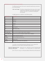
UPDATING SETTINGS VIA FTP
The following table outlines how to update the Modem Logger settings
remotely via FTP;
STEP
1
2
3
ACTION
Type any settings that need to be added or changed into a file
with the name ‘<unitname>-settings.new.’ the syntax is identical
to the ‘settings.ini’ file; there is no need to include settings that
remain unchanged.
Place the ‘<unitname>-settings.new.’ file on the FTP server in the
folder to which the Modem Logger unit connects. This is the root
directory by default, unless otherwise defined in the Loggers [FTP]
path setting.
During the next FTP session, the Logger will retrieve the
‘<unitname>-settings.new.’ file and merge it with the ‘settings.ini’
file on the SD card, after which the settings will be loaded into the
loggers memory and start operating according to the changes made.
• The setting ‘[FTP]getsettings’ is by default set to 1, even if
not declared in the ‘settings.ini’ file. This allows the updating
of settings via the FTP server, as described above. If you want
to prevent settings being updated remotely, you need to
declare ‘[FTP]getsettings=0’ in the ‘settings.ini’ file.
TIP
If you change the ‘settings.ini’ file to prevent remote updates, any
future changes to settings, including firmware updates will require
a field visit.
WARNING
37
If this function is selected it will increase your data traffic.
WARNING
• Including the line ‘[FTP]sendsettings=1’ in the ‘settings.ini’ file will
trigger the posting back of the complete updated ‘settings.ini’ file
from the SD card to the FTP server every time it connects.
This allows you to check all of the current updated settings.
TIP
METHODS OF UPDATING FIRMWARE
There are three methods available for updating the firmware for the
Modem Logger, two locally using a USB connection to a PC and one
remotely via FTP;
• Copy the file ‘firmware.upd’ onto the SD card using the
USB connection. Perform the command ‘reset’ via the
COM port command line. Remove the USB connector,
then re-insert once the update is complete.
• Copy the file ‘firmware.upd’ onto the SD card using a PC
card reader. Insert the SD card into the Modem Logger,
then power on the unit.
• Add the line ‘[FTP]getfirmware=1’ to ‘settings.ini’ . Make sure
that the new settings file is read; perform the ‘readsettings’
command if necessary. Rename the ‘firmware.upd’ file to
‘<unitname>-firmware.upd’ and place on the FTP server.
The logger will retrieve and install the firmware upon the
next FTP session.
While the firmware update is loading onto the logger, the green
LED will show a series of three short blinks until complete.
IMPORTANT
INFORMATION
When the logger is reconnected via the COM port, you can
check if the firmware has been successfully uploaded using
the ‘ver?’ command.
TIP
38
COMMANDS
VIA SMS TEXT
Commands issued via SMS will be received and handled upon the
loggers next scheduled GSM connection, which is usually the next
FTP transmission session.
SMS TEXT COMMAND
‘[group]field=parameter’
FUNCTION
Changes a specific setting, the syntax is identical to the
‘settings.ini’ file
‘*FTP*’
Force an FTP transmission
‘*status*’
Request all channel values in a reply SMS message
‘*reset*’
Force a full reset of the unit
‘*events*’
Rename the ‘events.txt’ file to ‘<unitname>-events.log’
and force a transmission via FTP
You can use multiple commands in a single SMS message by using a
semi colon (;) as a separator, for example;
‘[main]debug=1;*events*;*status*’
USING THE MODEM LOGGER AS A LOCAL LOGGER ONLY
You can use the Modem logger as a local data acquisition and storage
device only, without data transmission and remote management
through the GSM modem and without the need to install a SIM card.
To use the logger in this mode you will need to implement the following;
• Delete all the settings for the groups ‘[gsm]’ and ‘[FTP]’ in
the ‘settings.ini’ file
• Delete all channel alarm settings that are related to initiating
any FTP and SMS transmission in the ‘settings.ini’ file
• Change the default time of the logger ‘01-01-2010 00:00’
through the line command on the COM port;
‘time dd-mm-yyyy hh:mm:ss’.
Please refer to ‘Part III – Modem Logger Configuration and Data
Files - Available Line Commands - time <date/time>’ for more details.
WARNING
The default start-up time of the logger is ‘01-01-2010 00:00’.
Measurements and data logging will only start after the date
and time have been updated. Usually this is done automatically
at power-on by synching with an external internet time server
during the first GSM connection event. When using the unit as
a local logger this needs to be done manually through the line
command on the COM port.
39
Part V –
Connecting
Sensors &
Installation Guide
40
Contents
This section contains the following topics.
TOPIC
Connecting Sensors to the Modem Logger
Connecting a MEMS Piezometer and a Rain Gauge
Installing a Modem Logger in the Field
When You Are in the Field:
SEE PAGE
42
42
43
43
41
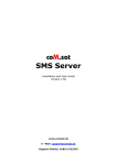
Connecting Sensors to the Modem Logger
CONNECTING A MEMS PIEZOMETER AND A RAIN GAUGE
itmsoil recommend a basic skill level for connecting sensors
+-
42
(e
E S G
SENSOR CONNECTIONS
SENSOR TERMINAL
Excitation V
E (excitation)
Signal out V
S (signal)
Ground
G (ground)
Pulse sensor +
+
Pulse sensor -
-
Installing a Modem Logger in the Field
WHEN YOU ARE
IN THE FIELD:
• Connect the sensors to the wiring panel on the Modem Logger.
• Ensure the mobile internet signal of your data plan carrier is
sufficiently strong. itmsoil recommend using a GSM/GPRS Radio
Signal Analyser which is available for purchase from itmsoil, (order
number ‘DI-SIG-TEST’).
• Insert the battery ensuring correct polarity.
• Mount or fix the Modem Logger using the appropriate fixings.
Please refer to Datasheet ‘D8 - Modem Logger – Ordering Information
- Accessories’ for fixing accessories.
43
Part VI –
Appendices
44
Contents
This section contains the following topics.
TOPIC
Appendix A – Example of ‘settings.ini’ file
Appendix B – Frequently Asked Questions
SEE PAGE
46
49
45
Appendix A – Example of ‘settings.ini’ file
MEMS PIEZOMETER, TIPPING BUCKET RAIN GAUGE, BATTERY, BAROMETRIC & ALARMING.
[main]name=SIL
[main]enable=1
[main]keepalivetime=13:00
[main]keepalivesms=1
[main]logseparator=59
[main]excvolt=2
[main]debug=1
[main]events=1
[main]buttonstatus=7
[main]buttonsms=1
[gsm]debug=1
[gsm]smsrecv=1
[gsm]cmd=AT+CPIN=0000
[gsm]gsmontime=10
[gsm]apn=yourapn
[gsm]login=yournetworkusername
[gsm]password=yournetworkpassword
[gsm]daytimeserver=utcnist.colorado.edu
[ftp]server=yourftpserveraddress
[ftp]login=yourftpusername
[ftp]password=yourftppassword
[ftp]time=07:00
[ftp]interval=1
[ftp]passive=1
[ftp]getsettings=1
[ftp]sendsettings=1
[sms]sms_1=44123456789
[sms]sms_2=44987654321
[sms]sms_3=44123450987
[sms]sms_4=44321067890
[channel_1]name=Piezo
[channel_1]enable=1
[channel_1]inputtype=2
[channel_1]measuretime=300
[channel_1]measureinterval=900
[channel_1]logtime=3600
[channel_1]units=Kpa
[channel_1]logging=1
[channel_1]precisionlog=3
46
[channel_1]piezocalc=-0.0000013:-0.2547:1673.18
[channel_1]calc=pcalc,-b
[channel_1]h_limit1=200
[channel_1]h_limit2=350
[channel_1]h_limit3=500
[channel_1]h_limit1on=1
[channel_1]h_limit2on=1
[channel_1]h_limit3on=1
[channel_1]alarmact=1
[channel_1]alarmclr=1
[channel_1]sample_a1=600
[channel_1]sample_a2=300
[channel_1]sample_a3=120
[channel_1]log_a1=600
[channel_1]log_a2=300
[channel_1]log_a3=120
[channel_1]ftppush_a1=1
[channel_1]ftppush_a2=1
[channel_1]ftppush_a3=1
[channel_1]smspush_a1=1
[channel_1]smspush_a2=1
[channel_1]smspush_a3=1
[channel_1]ftptime_a1=work
[channel_1]ftptime_a2=hour
[channel_1]ftptime_a3=min
[channel_1]ftpint_a2=1
[channel_1]ftpint_a3=5
[channel_1]smstext_a1=Water level zone1
[channel_1]smstext_a2=Water level zone2
[channel_1]smstext_a3=Water level zone3
[channel_1]smslist_a1=1,2
[channel_1]smslist_a2=2,3,4
[channel_1]smslist_a3=3,4
[channel_2]name=CH2_rain_mm1hr
47
[channel_2]enable=1
[channel_2]inputtype=1
[channel_2]debouncetime=5
[channel_2]calc=*0.2
[channel_2]units=mm
[channel_2]measureinterval=3600
[channel_2]logging=1
[channel_2]logtime=3600
[channel_2]precisionlog=1
[channel_2]h_limit1=4
[channel_2]h_limit2=10
[channel_2]h_limit1on=1
[channel_2]h_limit2on=1
[channel_2]alarmacttime=60
[channel_2]alarmclrtime=60
[channel_2]ftppush_a1=1
[channel_2]ftppush_a2=1
[channel_2]smspush_a1=1
[channel_2]smspush_a2=1
[channel_2]smstext_a1=Rain level 4mm
[channel_2]smstext_a2=Rain level 10mm
[channel_2]smslist_a1=2
[channel_2]smslist_a2=2,3
[channel_3]name=CH3_baro_mbar
[channel_3]enable=1
[channel_3]measureinterval=3600
[channel_3]logging=1
[channel_3]logtime=3600
[channel_3]calc=/10
[channel_3]units=Kpa
[channel_3]precisionlog=2
[channel_5]name=CH5_batt_V
[channel_5]measureinterval=86400
[channel_5]enable=1
[channel_5]logging=1
[channel_5]logtime=3600
[channel_5]precisionlog=2
48
Appendix B – Frequently Asked Questions
Do I need a static IP (internet provider) address to
operate the Modem Logger?
No, the Modem Logger connects to the FTP directory using a SIM
card (supplied by you). All communications with the web portal are
initialised by the Modem Logger; as a result no static IP is required.
QUESTION
What size of data plan will I need with my SIM card?
The size of data plan you need will depend on how often you are
reading the sensors and uploading the data. Soil Instruments would
suggest a 5MB data plan is more than sufficient for logging two
sensors plus battery voltage, every 10 minutes and uploading data
every day, allowing for some configuration changes throughout
the month (although logging and uploading rates can reduce or
increase the battery life).
Why doesn’t the logger mount as a COM Port?
Check that the ‘TinySense_V2.inf’ driver has been installed and the
COM Port is visible in ‘Device Manager’. If the device is connected,
the green LED will start blinking at regular intervals; 3 seconds off,
1 second on.
Why can’t I communicate with the unit?
Make sure the batteries have been installed with the correct polarity.
Why is my 0-10V sensor not working correctly?
Check the connections to the sensor. Using a Multimeter, check
the excitation voltage to the sensor between ‘E’ (excitation) and ‘G’
(ground). Using a Multimeter, check the voltage between ‘S’ (signal)
and ‘G’ (ground).
Why is my pulse sensor not working correctly?
Check the pulse from the sensor by using the Ω / Ω function
on your Multimeter. Move the sensor to generate the pulse.
As the contacts come together, the resistance on the Multimeter
will go from -1 to 0 and a an audio buzz will be heard (if the
option is available on your Multimeter).
49
SUPPORT
www.itmsoilsupport.com
+44 (0) 1825 765044
50
51
Bell Lane, Uckfield, East Sussex
TN22 1QL United Kingdom
t:
f:
+44 (0) 1825 765044
+44 (0) 1825 744398
e: [email protected]
w: www.itmsoil.com
Soil Instruments Ltd. Registered in England. Number: 07960087. Registered Office: 5th Floor, 24 Old Bond Street, London, W1S 4AW
52