1
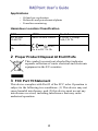
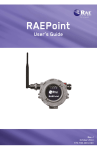
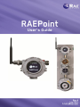
© Copyright 2012 RAE Systems Inc. 2 Contents 1 2 3 4 5 6 7 8 9 10 11 12 13 14 15 16 17 18 19 20 21 General Information..................................................................... 1 Proper Product Disposal At End Of Life ..................................... 2 FCC Part 15 Statement ................................................................ 2 Configurations ............................................................................. 3 General Specifications ................................................................. 5 Operation ..................................................................................... 6 Physical Description .................................................................... 7 Physical Dimensions .................................................................... 7 Installation And Access Instructions ........................................... 8 9.1 Mounting ...................................................................... 8 9.2 Instrument Disassembly ............................................. 10 9.3 Instrument Reassembly............................................... 11 Wiring....................................................................................... 12 Wiring Procedure ..................................................................... 13 11.1 RAEPoint Wireless Alarm Bar Wiring Note .............. 14 Switch Settings ......................................................................... 15 12.1 Pan ID (SW1) And Channel (SW2) ........................... 15 12.2 Mode Switch (SW3) ................................................... 16 12.3 Jumper JP1.................................................................. 17 Earth Grounding Instructions ................................................... 18 13.1 External Earth Grounding........................................... 18 13.2 Internal Earth Grounding ............................................ 18 13.3 Finished Grounding Wires.......................................... 19 Display/User Interface .............................................................. 20 Alarm Signal Summary ............................................................ 20 15.1 RAEPoint Host ........................................................... 21 15.2 RAEPoint Remote ...................................................... 22 15.3 RAEPoint Router ........................................................ 23 Appendix A: Controlled Section .............................................. 24 Scope ........................................................................................ 24 Responsibility ........................................................................... 24 Contents .................................................................................... 24 Technical Support..................................................................... 31 RAE Systems Contacts ............................................................. 31 1 General Information RAEPoint is an explosion-proof wireless device that both extends the range and enables remote relay functionality across a wireless mesh network. As part of a wireless mesh network, the RAEPoint communicates with wireless detectors and controllers and can direct any of its five internal relays to trigger audible and visible alarms. Remote alarm notifications are critical for many applications where local device alarms are simply not visible enough or loud enough to alert a wide area. RAEPoint relay settings can be fully configured wirelessly via the system controller. RAEPoint can also be configured as a wireless host, and communicate directly with detectors, providing a localized alarm notification solution that does not require a controller. RAE Systems offers the RAEPoint as a standalone unit, or as part of an integrated wireless alarm bar. Both RAEPoint and the RAEPoint Wireless Alarm Bar carry Class 1, Division 1, and ICEx/ATEX Zone 1 hazardous area location certification. Key Features Five internal SPDT relays Wireless transmission distance of 1000 ft (300m) point-to-point. Range can be extended by using wireless routers. Class 1, Division 1, and IECEx/ATEX Zone 1 hazardous area certification Available as standalone unit, or as a turn-key wireless alarm bar solution, mounted and pre-wired with two 5J xenon lights and a 110dB horn. Explosion-proof enclosure for hazardous environment applications LEDs indicate status 1 Applications Oil and gas exploration Refineries and petrochemical plants Fenceline monitoring Hazardous Location Classification IECEx ATEX North America IECEx SIR 12.0027X Sira 12ATEX 1085X Cl.I Div 1, Group A,B,C,D T6 Ex d ia IIC T6, Gb 0575 II 2G, Ex d ia IIC T6 Gb 2 Proper Product Disposal At End Of Life This symbol (crossed-out wheeled bin) indicates separate collection of waste electrical and electronic equipment in the EU countries. 3 FCC Part 15 Statement This device complies with Part15 of the FCC rules. Operation is subject to the following two conditions: (1) This device may not cause harmful interference, and (2) this device must accept any interference received, including interference that may cause undesired operation. 2 4 Configurations The RAEPoint can be ordered as a stand-alone wireless unit, or as an integrated Wireless Alarm Bar complete with 2 strobes and horn. Each RAEPoint can be configured as a Router, Remote, or Host on a wireless mesh network. RAEPoint Router A stand-alone, DC-powered, explosion-proof unit that acts as a permanent wireless router for mesh network systems. Includes aluminum enclosure with LED status indicators and an integrated wireless mesh radio. RAEPoint Remote & RAEPoint Host Stand-alone relay units include aluminum enclosure with LED status indicators, an integrated wireless mesh radio, and five integrated relays. RAEPoint Remote Wireless Alarm Bar & RAEPoint Host Wireless Alarm Bar Wireless alarm bar units include the RAEPoint fully integrated and certified with 2 xenon strobes and a 110dB horn. 3 Flexible Configurations RAEPoint, including the RAEPoint Wireless Alarm Bar, can be configured for large or small systems, and the network can be expanded or units removed, depending on the facility or facilities being monitored. Simple configuration that uses MeshGuard sensors and a RAEPoint Wireless Alarm Bar host Full network, including externally controlled devices 4 5 General Specifications Input Power Input Power Limit: 2.4W Vinput: 12-28VDC Five 3-level programmable alarm relays (30 VDC, 2A) Output Resistor load Max: 6A@24VDC or 6A@250VAC Inductive load Max: 2A@24VDC or 3A@250VAC IP Rating IP-65 Mechanical Interface 3/4" NPT Female Installation 2" pipe-holding or wall mounting Operation Environment Parameters Temperature -20° C to +55° C (-4° F to 131° F) Humidity 0 to 95% relative humidity, non-condensing Pressure 90 to 110kPa Display Display 4 LEDs (Network, Alarm, Communication, Mode) Physical Parameters Dimensions, LxWxH 257 x 201 x 107 mm (10.1" x 7.9" x 4.2") Material Alumina Weight 3.5 kg (7.7 lbs) 5 6 Operation Note: Prior to factory shipment, the RAEPoint is tested. However, the instrument should be tested after installation. 6 7 Physical Description The RAEPoint can be easily installed and integrated with various control systems. It is designed with flexible pipe-holding/wallmounting options and standard connection terminals. 8 Physical Dimensions The physical dimensions are as follows: 120mm 135mm 60mm 52mm 106.4mm 110mm 118mm 7 9 Installation And Access Instructions 9.1 Mounting First, decide where the transmitter will be mounted. (Refer to installation drawing, below.) Drill two holes in mounting surface, with the center of the holes 5.25" (135 mm) apart. 8 Besides being mounted to a wall, RAEPoint can be mounted on a pipe. Note: When installing the RAEPoint, make sure the antenna is installed in the left or right inlet (not the one on the bottom). Pole Wall 9 9.2 Instrument Disassembly Prior to service: Make sure power is OFF. Observe all Hazardous Location Safety procedures. 1. Loosen the hex locking screw on the housing lid. 2. Unscrew the housing lid by rotating it counterclockwise. 3. Press in on the clips on both sides of the display, and then lift out the circuit boards. 4. Turn the circuit boards over to access the switches and wiring points. Be careful not to damage the antenna wire between 10 the circuit boards and the antenna that passes through the housing. 9.3 Instrument Reassembly 1. Make sure all wires are connected to the terminal blocks and that the terminal blocks are firmly seated in the circuit board. 2. Turn over the circuit board/front panel. 3. Align the two clips with the mating points in the housing. 4. Click the board into place. 5. Screw on the housing top. 6. Screw down the locking screw. 11 10 Wiring The two terminal blocks in the RAEPoint accept 12AWG to 24AWG wire. One terminal block is for DC power, and the other is for relay connections. Terminal Block 1 (Power) Terminal Block 2 (Relays) 12 11 Wiring Procedure Inside the housing bottom, two green terminal block plugs are inserted into the terminal blocks on the PC boards. 1. The terminal block plugs accept 12 AWG to 24 AWG wire. Note: On the RAEPoint Wireless Alarm Bar, wiring from the Relay outputs and downline power are already complete. Only Power and Ground (earth) connections need to be made. See “Earth Grounding Instructions,” page 18, for information on proper grounding. 2. Lace the wires through the RAEPoint’s wire hole(s) and connect wires to the corresponding pin numbers of the terminal blocks: Terminal Block 1 Block 2 Terminal Definition Positive DC power supply for RAEPoint Positive DC power for downline units Negative DC power supply for RAEPoint Negative DC power for downline units Relay Output 5 Relay Output 4 Relay Output 3 Relay Output 2 Relay Output 1 Relay Common Terminal Block 1 (Power Connections) Terminal VN+ VN+ VNVNK5 K4 K3 K2 K1 COM Terminal Block 2 (Relay Connections) 13 No. 1 2 3 4 K5 K4 K3 K2 K1 COM 11.1 RAEPoint Wireless Alarm Bar Wiring Note The RAEPoint Wireless Alarm Bar already has most wiring done at the factory. It is only necessary to connect the positive and negative DC power supply wires and grounding (according to local requirements). Power and internal grounding wires should be fed through a connector at the bottom of the unit. Wires should be fed in through this point Internal wiring: Power To internal power points - DC + DC Terminal Block 1 (Power) To lights and horn Terminal Block 2 (Relays) 14 12 Switch Settings Configuration requires setting the two hexadecimal rotary-encoder switches that govern Pan ID and Channel. 12.1 Pan ID (SW1) And Channel (SW2) Make sure all units in the network, including an FMC2000 controller and any monitors, have the same Pan ID number and channel in order to communicate within the network. If you change the Pan ID number or Channel on the FMC2000, check the other units in the network, as well as the RAEPoint, to ensure they match. Use a small-blade screwdriver to turn each rotary encoder to the proper value. The following chart shows settings for the two encoders: SW1 PAN ID SW2 0 1 2 3 4 5 6 7 8 9 A B C D E F 999 998 997 996 995 994 993 992 991 990 989 988 987 986 985 984 0 1 2 3 4 5 6 7 8 9 A B C D E F Channel Ch0 Ch3 Ch4 Ch5 Ch6 Ch7 Ch8 Ch9 Ch15 Ch16 Ch17 Ch18 Ch19 Ch20 Ch25 Ch26 (ISM) 868 MHz 902 to 928 MHz 2.4 GHz IMPORTANT! Available channels vary by the internal wireless modem’s frequency. The channel can only be set to one that is available for the wireless modem frequency of your RAEPoint. For example, a RAEPoint with a 2.4 GHz modem can only use channels shown (15, 16, 17, 18, 19, 20, 25, 26). Note: After you change the settings on the rotary encoders, press the Reset button (labeled S4). 15 12.2 Mode Switch (SW3) Two DIP switches, labeled SW3, can be used to change the RAEPoint’s mode of operation (Host, Remote, or Router). The RAEPoint’s mode was set at the factory, but if you need to reconfigure it, set the switches as follows: Switch 1 On On Off Off * Switch 2 On Off On Off Mode RAEPoint Host RAEPoint Remote RAEPoint Router Factory Setting* Factory settings are indicated by the RAEPoint’s serial number: F081 F082 F083 RAEPoint Remote RAEPoint Router RAEPoint Host Note: After you change the settings on the two DIP switches, press the Reset button (labeled S4). 16 12.3 Jumper JP1 The jumper labeled JP1 has no effect on operation, so leave it in place, as shown: JP1 Important! Once the system is operational, test the functionality of all connected relays. 17 13 Earth Grounding Instructions 13.1 External Earth Grounding Fasten the crimped ground wire with hardware as illustrated below. The wire should have a minimum cross-section area of 4mm2 for its conductor. M4 Screw M4 Split washer M4 flat washer Crimped terminal Wire 2 (Min. 4 mm cross-section) 13.2 Internal Earth Grounding Use the same hardware as shown in the illustration of external earth grounding. The wire should be no less than the size of the power lines. Signal grounding can connect to a cable’s shielding layer if shielded cable is used. If a separate wire is used for grounding, its cross section should be greater than that of the power line. Internal earth grounding 18 13.3 Finished Grounding Wires Internal and external grounding are shown here, as well as an alternate external grounding point. Always follow local electrical guidelines. External earth grounding Internal earth grounding 19 Alternate earth grounding point 14 Display/User Interface The RAEPoint’s user interface consists of four status LEDs. There are no buttons or controls. All settings are made internally. 15 Alarm Signal Summary The following are reading-related alarms. Net Alarm Comm Mode Function Network Status Indicator Alarm Type Indicator Communications Activity Indicator Device Type Indicator Host Remote Router Blinks once per second if in network. Off when there is no network Blinks for On during On during any fault any relay any relay action action Blinks for Blinks for any fault any fault Blinks for all communication Off at any other time On Blinks once Blinks per second twice per second 20 15.1 RAEPoint Host The LEDs on the RAEPoint Host indicate the following conditions: Net Blinks when a network is established. Off when a network is absent. Alarm Glows solid red when detectors are in alarm Blinks red when detectors have a fault. Blinks red when DC supply voltage is below 11 volts. Comm Flashes when there is RF (radio frequency) send/receive activity. Mode Glows solid green. Notes Relay Definitions: Relay 1 Relay 2 Relay 3 Relay 4 Relay 5 Any alarms Any low alarms Any high alarms High LEL alarms High H2S alarms 21 15.2 RAEPoint Remote Note: RAEPoint Remote can only operate with an FMC2000 Controller. The LEDs on the RAEPoint Remote indicate the following conditions: Net Blinks when a network is established. Off when a network is absent. Alarm Glows solid red when detectors are in alarm Blinks red when DC supply voltage is below 11 volts. Comm Flashes when there is RF (radio frequency) send/receive activity. Mode Blinks one time per second (green). Notes Relay Definitions: The RAEPoint Remote’s relays operate identically to the FMC2000 Controller on this network. 22 15.3 RAEPoint Router Note: A RAEPoint Router can operate as a router for any device using the same radio type. The LEDs on the RAEPoint Router indicate the following conditions: Net Blinks when a network is established. Off when a network is absent. Alarm Blinks red when DC supply voltage is below 11 volts. Comm Flashes when there is RF (radio frequency) send/receive activity. Mode Blinks two times per second (green). 23 16 Appendix A: Controlled Section 17 Scope The scope of this document is to identify the section of the RAEPoint controlled part of the manual. 18 Responsibility The included sections cannot be changed without prior approval from the Notified Body. 19 Contents Below are the sections controlled by the Notified Body, including all safety-related information in the manual. Controlled sections are: 1.Warnings and directive information 2. Marking of the RAEPoint 3. Hazardous Location Classifications 4. Instructions for Safe Use 5. Connections and Ratings 6. Maintenance 7. Physical dimensions 24 1. Warnings And Directive Information - READ BEFORE OPERATING This manual must be carefully read by all individuals who have or will have the responsibility of using, maintaining, or servicing this product. The product will perform as designed only if it is used, maintained, and serviced in accordance with the manufacturer’s instructions. CAUTION! To reduce the risk of electric shock, turn the power off before removing the instrument cover. Disconnect the power before removing the sensor module for service. Never operate the instrument when the cover is removed. Remove instrument cover and sensor module only in an area known to be nonhazardous. Use of non-RAE Systems components will void the warranty and can compromise the safe performance of this product. 25 2. Marking Of RAEPoint RAEPoint is certified according to ATEX and the IECEx scheme and CSA for US and Canada as protected by a flameproof enclosure, and the antenna barrier is used on intrinsically safe principles. The product is marked with the following information: RAE Systems Inc. 3775 N. 1st. St. San Jose, CA95134 USA Serial number: XXXXXXXXXX Year of production RAEPoint IECEx IECEx SIR 12.0027X ATEX Sira 12ATEX 1085X Ex d ia IIC T6, Gb 0575 II 2G, Ex d ia IIC T6 Gb North America Cl.I Div 1, Group A,B,C,D T6 -20ºC < Tamb < +55ºC WARNING: READ USER’S MANUAL FOR SAFETY PRECAUTIONS. WARNING: DO NOT OPEN WHEN AN EXPLOSIVE ATMOSPHERE MAY BE PRESENT. REFER TO USER MANUAL FOR ENTRY TYPE AND SIZE 26 3. Hazardous Location Classification Hazardous Areas Classified By Zones RAEPoint is intended to be used in hazardous areas classified for Zone 1 or Zone 2, within the temperature range of -20o C to +55o C, where gases of explosion groups IIA, IIB or IIC and T6 may be present. Hazardous Areas Classified By Divisions RAEPoint is intended to be used in hazardous areas classified for Class I Div. 1 or 2, within the temperature range of -20º C to +55º C, where gases of explosion groups A, B, C or D and temperature class T6 may be present. 4. Instructions For Safe Use None. 5. Connections And Ratings Input/Output The rated RAEPoint input/output are as follows: Input: 2.4W Vinput: 12-28VDC 6. Maintenance Installation and Access Instructions When used in North America, a minimum of 18" (457mm) of explosion-proof conduit must be used at cable entry in group B atmospheres. CSA requires seals in conduit exceeding 5' (1.524 m) in group C atmospheres. The appropriate regulations for installation, service and repair must be properly observed during such activities. To prevent ignition of hazardous atmospheres, area must be free of flammable vapors and supply circuit must be disconnected before removing cover. 27 Earth Grounding Instructions External Earth Grounding Fasten the crimped ground wire with hardware as illustrated here. The wire should have a minimum cross-section area of 4mm2 for its conductor. Internal Earth Grounding Internal earth grounding Use the same hardware as shown in the illustration of external earth grounding. The wire should be no less than the size of the power lines. Finished Grounding Wires Internal and external grounding are shown here, as well as an alternate external grounding point. Always follow local electrical guidelines. External earth grounding Alternate groundingpoint grounding Internal earth grounding 28 7. Physical Dimensions RAEPoint can be easily installed and integrated with various control systems with its flexible pipe-holding/wall-mounting options and standard connection terminals. Entries: RAEPoint is provided with three female 3/4" - 14 NPT cable entry holes tapped into its side walls; one 3/4" - 14 NPT containing the antenna coupler for mounting of the external antenna. The physical dimensions are as follows: 120mm 135mm 60mm 52mm 106.4mm 110mm 118mm 29 8. Models Of RAEPoint Model Number RRA2000 RRA2000 RRA2000 Product Name RAEPoint Wireless Switch Remote RAEPoint Wireless Router RAEPoint Wireless Switch Host / RAEPoint GateWay 30 20 Technical Support To contact RAE Systems Technical Support: Monday through Friday, 7:00AM to 5:00PM Pacific (US) Time Phone (toll-free): +1 888-723-4800 Phone: +1 408-952-8461 Email: [email protected] Life-critical after-hours support is available: +1 408-952-8200 select option 9 21 RAE Systems Contacts RAE Systems World Headquarters 3775 N. First St. San Jose, CA 95134-1708 USA Phone: +1 408.952.8200 Fax: +1 408.952.8480 E-mail: [email protected] Web Site: www.raesystems.com RAE Systems Technical Support Monday through Friday, 7:00AM to 5:00PM Pacific Time Phone: +1.408.952.8461 Email: [email protected] Life-critical after-hours support is available +1.408.952.8200 select option 9 31 RAE Systems Europe ApS Kirstinehøj 23 A DK-2770 Kastrup Denmark Phone: +45 86 52 51 55 Fax: +45 86 52 51 77 [email protected] [email protected] [email protected] Web: www.raesystems.eu RAE Systems UK Ltd D5 Culham Innovation Centre Culham Science Centre Abingdon, Oxon OX14 3DB United Kingdom Phone: +44 1865408368 Fax: +44 1235531119 Mobile: +44 7841362693 Email: [email protected] RAE Systems France 336, rue de la fée des eaux 69390 Vernaison France Phone: +33 4 78 46 16 65 Fax: +33 4 78 46 25 98 Email: [email protected] Web: www.raesystems.fr 32 RAE BeNeLux BV Rijndal 20 2904 DC Capelle a/d IJssel Phone: +31 10 4426149 Fax: +31 10 4426148 Email: [email protected] Web: www.rae.nl RAE Systems Spain, s.l. Av. Remolar, 31 08820 El Prat de Llobregat Spain Phone: +34 933 788 352 Fax: +34 933 788 353 Mobile: +34 687 491 106 Email: [email protected] Web: www.raespain.com RAE Systems Middle East LOB 7, Ground Floor, Office 19, Jebel Ali Free Zone Dubai, United Arab Emirates Phone: +971.4.887.5562 Email: [email protected] RAE Systems (Hong Kong) Ltd. Room 8, 6/F, Hong Leong Plaza 33 Lok Yip Road Fanling, N.T, Hong Kong Phone: +852.2669.0828 Fax: +852.2669.0803 Email: [email protected] 33 RAE Systems Japan Marunouchi Nakadori Bldg 6F-617-B, 2-3, Marunouchi 2-Chome, Chiyoda-ku, Tokyo, 100-0005 Japan Phone: +81-3-6269-9646 Fax: +81-3-6269-9647 Email: [email protected] RAE Systems Korea #1010, DaeMyungAnsVill First, Sang-Dong 412-2, Wonmi-Gu, Bucheon, Kyungki-Do, Korea Phone: 82-32-328-7123 Fax: 82-32-328-7127 Email: [email protected] 34