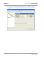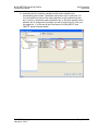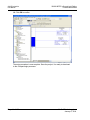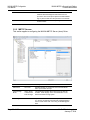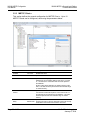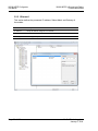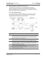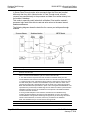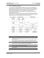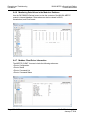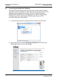
1
MVI69L-MBTCP CompactLogix Platform Modbus TCP/IP Lite Communication Module January 6, 2014 USER MANUAL Your Feedback Please We always want you to feel that you made the right decision to use our products. If you have suggestions, comments, compliments or complaints about our products, documentation, or support, please write or call us. How to Contact Us ProSoft Technology 5201 Truxtun Ave., 3rd Floor Bakersfield, CA 93309 +1 (661) 716-5100 +1 (661) 716-5101 (Fax) www.prosoft-technology.com [email protected] Copyright © 2014 ProSoft Technology, Inc., All rights reserved. MVI69L-MBTCP User Manual January 6, 2014 ® ® ® ® ® ProSoft Technology , ProLinx , inRAx , ProTalk , and RadioLinx are Registered Trademarks of ProSoft Technology, Inc. All other brand or product names are or may be trademarks of, and are used to identify products and services of, their respective owners. In an effort to conserve paper, ProSoft Technology no longer includes printed manuals with our product shipments. User Manuals, Datasheets, Sample Ladder Files, and Configuration Files are provided on the enclosed DVD, and are available at no charge from our web site: http://www.prosoft-technology.com Content Disclaimer This documentation is not intended as a substitute for and is not to be used for determining suitability or reliability of these products for specific user applications. It is the duty of any such user or integrator to perform the appropriate and complete risk analysis, evaluation and testing of the products with respect to the relevant specific application or use thereof. Neither ProSoft Technology nor any of its affiliates or subsidiaries shall be responsible or liable for misuse of the information contained herein. Information in this document including illustrations, specifications and dimensions may contain technical inaccuracies or typographical errors. ProSoft Technology makes no warranty or representation as to its accuracy and assumes no liability for and reserves the right to correct such inaccuracies or errors at any time without notice. If you have any suggestions for improvements or amendments or have found errors in this publication, please notify us. No part of this document may be reproduced in any form or by any means, electronic or mechanical, including photocopying, without express written permission of ProSoft Technology. All pertinent state, regional, and local safety regulations must be observed when installing and using this product. For reasons of safety and to help ensure compliance with documented system data, only the manufacturer should perform repairs to components. When devices are used for applications with technical safety requirements, the relevant instructions must be followed. Failure to use ProSoft Technology software or approved software with our hardware products may result in injury, harm, or improper operating results. Failure to observe this information can result in injury or equipment damage. © 2014 ProSoft Technology. All rights reserved. Printed documentation is available for purchase. Contact ProSoft Technology for pricing and availability. North America: +1.661.716.5100 Asia Pacific: +603.7724.2080 Europe, Middle East, Africa: +33 (0) 5.3436.87.20 Latin America: +1.281.298.9109 Important Safety Information - MVI69L-MBTCP North America Warnings A B C D This Equipment is Suitable For Use in Class I, Division 2, Groups A, B, C, D or Non-Hazardous Locations Only. Warning – Explosion Hazard – Substitution of Any Components May Impair Suitability for Class I, Division 2. Warning – Explosion Hazard – Do Not Disconnect Equipment Unless Power Has Been Switched Off Or The Area is Known To Be Non-Hazardous. The subject devices are powered by a Switch Model Power Supply (SMPS) that has regulated output voltage of 5 VDC. ATEX Warnings and Conditions of Safe Usage: Power, Input, and Output (I/O) wiring must be in accordance with the authority having jurisdiction A Warning - Explosion Hazard - When in hazardous locations, turn off power before replacing or wiring modules. B Warning - Explosion Hazard - Do not disconnect equipment unless power has been switched off or the area is known to be non-hazardous. C These products are intended to be mounted in an IP54 enclosure. The devices shall provide external means to prevent the rated voltage being exceeded by transient disturbances of more than 40%. This device must be used only with ATEX certified backplanes. DO NOT OPEN WHEN ENERGIZED Agency Approvals and Certifications Agency ATEX; Category 3, Zone 2 CE Mark CSA; CB Safety Environmental KCC RoHS Compliant UL/cUL; Class 1, Div. 2 Groups A, B, C, D MVI69L-MBTCP ♦ CompactLogix Platform Communication Module Contents User Manual Contents Your Feedback Please ........................................................................................................................ 2 How to Contact Us .............................................................................................................................. 2 Important Safety Information - MVI69L-MBTCP ................................................................................. 3 1 Start Here 1.1 1.2 1.3 1.4 1.5 1.6 2 9 System Requirements ............................................................................................. 10 Deployment Checklist.............................................................................................. 11 Package Contents ................................................................................................... 11 Setup Jumper .......................................................................................................... 12 Installing the Module in the Rack ............................................................................ 13 DVD Contents ......................................................................................................... 16 Add-On Instruction 2.1 2.2 2.2.1 2.2.2 2.3 2.4 2.4.1 2.4.2 2.4.3 2.5 2.6 2.6.1 2.6.2 3 Installing ProSoft Configuration Builder .................................................................. 18 Generating the AOI (.L5X) File in ProSoft Configuration Builder ............................ 19 Creating a New Project in PCB ............................................................................... 19 Exporting the .L5X File from PCB ........................................................................... 22 Creating a New RSLogix 5000 Project .................................................................... 24 Creating the Module in an RSLogix 5000 Project ................................................... 25 Installing an Add-On Profile .................................................................................... 25 Creating a Module in the Project Using an Add-On Profile ..................................... 27 Creating a Module in the Project Using a Generic 1769 Module Profile ................. 29 Importing the Add-On Instruction ............................................................................ 33 Adding Multiple Modules in the Rack (Optional) ..................................................... 36 Adding a New Module in PCB ................................................................................. 36 Adding a new module in RSLogix 5000 .................................................................. 38 MVI69L-MBTCP Configuration 3.1 3.1.1 3.1.2 3.1.3 3.1.4 3.2 3.2.1 3.2.2 3.2.3 3.2.4 3.2.5 3.2.6 3.3 3.4 4 ProSoft Technology, Inc. January 6, 2014 45 Basic PCB Functions ............................................................................................... 46 Creating a New PCB Project and Exporting an .L5X File ....................................... 46 Renaming PCB Objects .......................................................................................... 46 Editing Configuration Parameters ........................................................................... 46 Printing a Configuration File .................................................................................... 48 Module Configuration Parameters .......................................................................... 49 Module ..................................................................................................................... 49 MBTCP Servers ...................................................................................................... 50 MBTCP Client x ....................................................................................................... 52 MBTCP Client x Commands ................................................................................... 55 Ethernet 1 ................................................................................................................ 58 Static ARP Table ..................................................................................................... 59 Downloading the Configuration File to the Processor ............................................. 60 Uploading the Configuration File from the Processor ............................................. 63 Backplane Data Exchange 4.1 17 67 Backplane Data Transfer......................................................................................... 68 Page 5 of 152 Contents User Manual MVI69L-MBTCP ♦ CompactLogix Platform Communication Module 4.2 4.2.1 4.2.2 4.2.3 4.3 4.3.1 4.3.2 5 Normal Data Transfer ............................................................................................. 69 Write Block: Request from the Processor to the Module ........................................ 69 Read Block: Response from the Module to the Processor ..................................... 69 Read and Write Block Transfer Sequences ........................................................... 70 Data Flow Between the Module and Processor ..................................................... 71 Server Driver Overview ........................................................................................... 71 Client Driver Overview ............................................................................................ 73 Using Controller Tags 5.1 5.1.1 5.2 5.2.1 5.3 5.3.1 5.3.2 5.3.3 5.3.4 5.3.5 6 Controller Tags ....................................................................................................... 76 MVI69L-MBTCP Controller Tags ............................................................................ 76 User-Defined Data Types (UDTs)........................................................................... 78 MVI69L-MBTCP User-Defined Data Types ............................................................ 78 Controller Tag Overview ......................................................................................... 80 MBTCP.CONFIG .................................................................................................... 80 MBTCP.DATA ......................................................................................................... 80 MBTCP.CONTROL ................................................................................................. 81 MBTCP.STATUS .................................................................................................... 86 MBTCP.UTIL........................................................................................................... 89 Diagnostics and Troubleshooting 6.1 6.2 6.2.2 6.3 6.3.1 6.4 6.4.1 6.4.2 6.4.3 6.4.4 6.4.5 6.4.6 6.4.7 6.5 6.6 7 Reference 7.1 7.1.1 7.1.2 7.2 7.2.1 7.2.2 7.2.3 7.2.4 7.2.5 7.2.6 7.2.7 7.2.8 Page 6 of 152 75 91 Ethernet LED Indicators .......................................................................................... 92 LED Status Indicators ............................................................................................. 92 Troubleshooting the LEDs ...................................................................................... 93 Connecting the PC to the Module's Ethernet Port .................................................. 94 Setting Up a Temporary IP Address ....................................................................... 94 Connecting to the Diagnostics Menu in ProSoft Configuration Builder .................. 97 Diagnostics Menu ................................................................................................... 99 Monitoring General Information .............................................................................. 99 Monitoring Network Configuration Information ..................................................... 100 Monitoring Backplane Status Information ............................................................. 100 Modbus Server Driver Information ........................................................................ 101 Monitoring Data Values in the Module’s Database............................................... 102 Modbus Client Driver Information ......................................................................... 102 Communication Error Codes ................................................................................ 103 Connecting to the Module’s Webpage .................................................................. 104 105 Product Specifications .......................................................................................... 106 General Specifications - Modbus Client/Server .................................................... 106 Hardware Specifications ....................................................................................... 107 About the Modbus Protocol .................................................................................. 108 Commands Supported by the Module .................................................................. 109 Read Coil Status (Function Code 01) ................................................................... 109 Read Input Status (Function Code 02) ................................................................. 110 Read Holding Registers (Function Code 03) ........................................................ 112 Read Input Registers (Function Code 04) ............................................................ 113 Force Single Coil (Function Code 05) .................................................................. 113 Preset Single Register (Function Code 06) .......................................................... 115 Diagnostics (Function Code 08) ........................................................................... 115 ProSoft Technology, Inc. January 6, 2014 MVI69L-MBTCP ♦ CompactLogix Platform Communication Module 7.2.9 7.2.10 7.3 7.3.1 7.3.2 7.4 7.4.1 7.4.2 7.4.3 7.4.4 7.4.5 7.4.6 7.4.7 7.4.8 7.4.9 7.4.10 7.4.11 7.4.12 7.4.13 7.4.14 7.4.15 7.4.16 7.4.17 7.4.18 7.4.19 7.4.20 7.4.21 7.4.22 7.4.23 7.5 7.5.1 7.5.2 8 Contents User Manual Force Multiple Coils (Function Code 15) ............................................................... 118 Preset Multiple Registers (Function Code 16) ...................................................... 119 Floating-Point Support ........................................................................................... 120 ENRON Floating-Point Support ............................................................................ 120 Configuring Floating-Point Data Transfer.............................................................. 121 Function Blocks ..................................................................................................... 126 Event Command Blocks ........................................................................................ 127 Client Status Request/Response Blocks............................................................... 128 Event Sequence Request Blocks .......................................................................... 129 Event Sequence Command Error Status Blocks .................................................. 130 Get Queue and Event Sequence Block Counts Block .......................................... 131 Command Control Blocks...................................................................................... 132 Add Event with Data for Client Blocks ................................................................... 133 Get Event with Data Status Block ......................................................................... 134 Get General Module Status Data Block ................................................................ 135 Set Driver and Command Active Bits Block .......................................................... 137 Get Driver and Command Active Bits Block.......................................................... 138 Pass-through Formatted Block for Functions 6 and 16 with Word Data Block ..... 139 Pass-through Formatted Block for Functions 6 and 16 with Float Data Block ...... 140 Pass-through Formatted Block for Function 5....................................................... 141 Pass-through Formatted Block for Function 15 .................................................... 142 Pass-through Formatted Block for Function 22 .................................................... 143 Pass-through Formatted Block for Function 23 .................................................... 143 Pass-through Block for Function 99 ...................................................................... 144 Set Module Time Using Received Time Block ...................................................... 145 Pass Module Time to Processor Block ................................................................. 145 Reset Status Block ................................................................................................ 146 Warm-boot Control Block ...................................................................................... 147 Cold-boot Control Block ........................................................................................ 147 Ethernet Cable Connections ................................................................................. 148 Ethernet Cable Specifications ............................................................................... 148 Ethernet Performance ........................................................................................... 148 Support, Service & Warranty 149 8.1 8.2 Contacting Technical Support ............................................................................... 149 Warranty Information ............................................................................................. 150 Index 151 ProSoft Technology, Inc. January 6, 2014 Page 7 of 152 MVI69L-MBTCP ♦ CompactLogix Platform Communication Module ProSoft Technology, Inc. January 6, 2014 User Manual Page 8 of 152 MVI69L-MBTCP ♦ CompactLogix Platform Communication Module 1 Start Here User Manual Start Here In This Chapter System Requirements ........................................................................... 10 Deployment Checklist ............................................................................ 11 Package Contents ................................................................................. 11 Setup Jumpers ...................................................................................... 12 Installing the Module in the Rack........................................................... 13 DVD Contents ....................................................................................... 16 To get the most benefit from this User Manual, the user should have the following skills: Rockwell Automation® RSLogix™ software: launch the program, configure ladder logic, and transfer the ladder logic to the processor Microsoft Windows: install and launch programs, execute menu commands, navigate dialog boxes, and enter data Hardware installation and wiring: install the module, and safely connect Modbus and CompactLogix devices to a power source and to the MVI69LMBTCP module’s Ethernet port ProSoft Technology, Inc. January 6, 2014 Page 9 of 152 Start Here User Manual 1.1 MVI69L-MBTCP ♦ CompactLogix Platform Communication Module System Requirements The MVI69L-MBTCP module requires the following minimum hardware and software components: Rockwell Automation CompactLogix® processor (firmware version 10 or higher), with compatible power supply, and one free slot in the rack for the MVI69L-MBTCP module. Important: The MVI69L-MBTCP module has a power supply distance rating of 4 (L43 and L45 installations on first 2 slots of 1769 bus). It consumes 450 mA at 5 Vdc. The module requires 450 mA of available 5 Vdc power Rockwell Automation RSLogix 5000 programming software version 16 or higher Rockwell Automation RSLinx® communication software version 2.51 or higher ProSoft Configuration Builder (PCB) (included) ProSoft Discovery Service (PDS) (included in PCB) Pentium® II 450 MHz minimum. Pentium III 733 MHz (or better) recommended Supported operating systems: ® o Microsoft Windows 7 o Microsoft Windows Vista o Microsoft Windows XP Professional with Service Pack 1 or 2 o Microsoft Windows 2000 Professional with Service Pack 1, 2, or 3 o Microsoft Windows Server 2003 128 Mbytes of RAM minimum, 256 Mbytes of RAM recommended 100 Mbytes of free hard disk space (or more based on application requirements) 256-color VGA graphics adapter, 800 x 600 minimum resolution (True Color 1024 768 recommended) DVD drive Note: The Hardware and Operating System requirements in this list are the minimum recommended to install and run software provided by ProSoft Technology®. Other third party applications may have different minimum requirements. Refer to the documentation for any third party applications for system requirements. Page 10 of 152 ProSoft Technology, Inc. January 6, 2014 MVI69L-MBTCP ♦ CompactLogix Platform Communication Module 1.2 Start Here User Manual Deployment Checklist Before configuring the module, consider the following questions. 1 ____________ Is this a new application or an integration into an existing application? Most applications will use the Sample Add-On Instruction without any edits. 2 ____________ What slot number in the rack will the MVI69L-MBTCP module occupy? 3 ____________ Are RSLogix 5000 and RSLinx software installed? RSLogix and RSLinx are required to communicate to the CompactLogix processor. 4 ____________ How many words of data are needed to transfer in the application (from CompactLogix to Module / to CompactLogix from Module)? 1.3 Package Contents The following components are included with the MVI69L-MBTCP module, and are all required for installation and configuration. Important: Before beginning the installation, please verify all of the following items are present. Qty. Part Name Part Number Part Description 1 MVI69L-MBTCP Module MVI69L-MBTCP Modbus communication module 1 Ethernet Cable RL-CBL025 Ethernet straight-through cable 1 ProSoft Solutions DVD DVD-001 Contains ProSoft Configuration Builder (PCB) and ProSoft Discovery Service (PDS) software. Files can also be found at www.prosoft-technology.com If any of these components are missing, please contact ProSoft Technology Support for replacement parts. ProSoft Technology, Inc. January 6, 2014 Page 11 of 152 Start Here User Manual 1.4 MVI69L-MBTCP ♦ CompactLogix Platform Communication Module Setup Jumper The Setup Jumper acts as "write protection" for the module’s firmware. In "write protected" mode, the Setup pins are not connected, and the module’s firmware cannot be overwritten. The module is shipped with the Setup jumper OFF. If an update of the firmware is needed, apply the Setup jumper to both pins. The following illustration shows the MVI69L-MBTCP jumper configuration, with the Setup Jumper OFF. Page 12 of 152 ProSoft Technology, Inc. January 6, 2014 MVI69L-MBTCP ♦ CompactLogix Platform Communication Module 1.5 Start Here User Manual Installing the Module in the Rack Make sure the processor and power supply are installed and configured before installing the MVI69L-MBTCP module. Refer to the Rockwell Automation product documentation for installation instructions. Warning: Please follow all safety instructions when installing this or any other electronic devices. Failure to follow safety procedures could result in damage to hardware or data, or even serious injury or death to personnel. Refer to the documentation for each device to be connected to verify that suitable safety procedures are in place before installing or servicing the device. After the jumper placements are verified, insert the MVI69L-MBTCP into the rack. Use the same technique recommended by Rockwell Automation to remove and install CompactLogix modules. Warning: This module is not hot-swappable! Always remove power from the rack before inserting or removing this module, or damage may result to the module, the processor, or other connected devices. 1 Align the module using the upper and lower tongue-and-groove slots with the adjacent module and slide forward in the direction of the arrow. ProSoft Technology, Inc. January 6, 2014 Page 13 of 152 Start Here User Manual 2 3 4 MVI69L-MBTCP ♦ CompactLogix Platform Communication Module Move the module back along the tongue-and-groove slots until the bus connectors on the MVI69 module and the adjacent module line up with each other. Push the module’s bus lever back slightly to clear the positioning tab and move it firmly to the left until it clicks. Ensure that it is locked firmly in place. Close all DIN-rail latches. Page 14 of 152 ProSoft Technology, Inc. January 6, 2014 MVI69L-MBTCP ♦ CompactLogix Platform Communication Module 5 Start Here User Manual Press the DIN-rail mounting area of the controller against the DIN-rail. The latches will momentarily open and lock into place. ProSoft Technology, Inc. January 6, 2014 Page 15 of 152 Start Here User Manual 1.6 MVI69L-MBTCP ♦ CompactLogix Platform Communication Module DVD Contents The DVD contains all the necessary files for the module. The User Manual, ProSoft Configuration Builder (PCB), and the sample Add-On Instruction are among the files. If the DVD is not present, please visit www.prosoft-technology.com for the latest files. Page 16 of 152 ProSoft Technology, Inc. January 6, 2014 MVI69L-MBTCP ♦ CompactLogix Platform Communication Module 2 Add-On Instruction User Manual Add-On Instruction In This Chapter Installing ProSoft Configuration Builder ................................................. 18 Generating the AOI (.L5X) File in ProSoft Configuration Builder .......... 19 Creating a New RSLogix 5000 Project .................................................. 24 Creating the Module in an RSLogix5000 Project ................................... 25 Importing the Add-On Instruction........................................................... 33 Adding Multiple Modules in the Rack (Optional) .................................... 36 The .L5X file contains the Add-On Instruction (AOI), user-defined data types, controller tags and ladder logic required to configure the MVI69L-MBTCP module. This file is generated by ProSoft Configuration Builder software and imported into RSLogix 5000. ProSoft Technology, Inc. January 6, 2014 Page 17 of 152 Add-On Instruction User Manual 2.1 MVI69L-MBTCP ♦ CompactLogix Platform Communication Module Installing ProSoft Configuration Builder The ProSoft Configuration Builder installation file can be found on the product DVD or from our web site: http://www.prosoft-technology.com. The filename contains the version of PCB. For example, PCB_4.1.0.4.0206.exe Copy the installation file to the local hard drive and run the PCB.exe file to start the InstallShield Wizard. Follow the InstallShield Wizard to properly install PCB. Page 18 of 152 ProSoft Technology, Inc. January 6, 2014 MVI69L-MBTCP ♦ CompactLogix Platform Communication Module 2.2 Add-On Instruction User Manual Generating the AOI (.L5X) File in ProSoft Configuration Builder The following sections describe the steps required to set up a new configuration project in ProSoft Configuration Builder (PCB), and to export the .L5X file for the project. 2.2.1 Creating a New Project in PCB To begin, start the PCB software. PCB’s window consists of a tree view on the left, and an information pane and configuration pane on the right side of the window. The tree view consists of folders for Default Project and Default Location, with a Default Module in the Default Location folder. The following illustration shows the ProSoft Configuration Builder window with a new project. ProSoft Technology, Inc. January 6, 2014 Page 19 of 152 Add-On Instruction User Manual MVI69L-MBTCP ♦ CompactLogix Platform Communication Module To add the MVI69L-MBTCP module to the project 1 In the tree view, right-click DEFAULT MODULE. Select CHOOSE MODULE TYPE from the shortcut menu. This action opens the Choose Module Type dialog box. Page 20 of 152 ProSoft Technology, Inc. January 6, 2014 MVI69L-MBTCP ♦ CompactLogix Platform Communication Module Add-On Instruction User Manual 2 In the Product Line Filter area of the dialog box, click the MVI69L radio button. In the Select Module Type dropdown list, select MVI69L-MBTCP, and click OK to save the settings and return to the ProSoft Configuration Builder window. 3 The MVI69L-MBTCP module icon will now be visible in the tree view. ProSoft Technology, Inc. January 6, 2014 Page 21 of 152 Add-On Instruction User Manual MVI69L-MBTCP ♦ CompactLogix Platform Communication Module 2.2.2 Exporting the .L5X File from PCB 1 Expand the MVI69L-MBTCP icon by clicking the [+] symbol beside it. Similarly, expand the open the Edit - Module dialog box. 2 icon. Double-click the Module icon to Edit the Slot Number indicating where the module will be placed in the 1769 bus. The Slot Number parameter in the PCB configuration affects the format of the .L5X file that is exported. This parameter identifies the residing slot of the module in the CompactLogix rack. Page 22 of 152 ProSoft Technology, Inc. January 6, 2014 MVI69L-MBTCP ♦ CompactLogix Platform Communication Module Add-On Instruction User Manual 3 Click OK to close the Edit – Module dialog box. The .L5X file is now ready to be exported to the PC/Laptop. 4 Right-click the MVI69L-MBTCP icon in the project tree and select EXPORT AOI FILE. 5 Save the .L5X file to the PC/Laptop in an easily found location, such as Windows Desktop. ProSoft Technology, Inc. January 6, 2014 Page 23 of 152 Add-On Instruction User Manual 2.3 MVI69L-MBTCP ♦ CompactLogix Platform Communication Module Creating a New RSLogix 5000 Project 1 Open the FILE menu, and select NEW. 2 Select the CompactLogix processer model. 3 Select REVISION 16 or newer. 4 Enter a name for the processor, such as My_Controller. 5 Select the CompactLogix chassis type. Page 24 of 152 ProSoft Technology, Inc. January 6, 2014 MVI69L-MBTCP ♦ CompactLogix Platform Communication Module 2.4 Add-On Instruction User Manual Creating the Module in an RSLogix 5000 Project In an RSLogix 5000 project, an Add-On Profile (AOP) can be used to specifically identify the MVI69L-MBTCP when selecting the type of module to be installed in slot x. Add-On Profiles are supported in RSLogix 5000 version 15 and newer. If using an AOP is not an option, please see page 29 to install the module using a Generic 1769 Module profile. 2.4.1 Installing an Add-On Profile Download the MPSetup.exe file from the product webpage or DVD onto the local hard drive. Make sure RSLogix 5000 and RSLinx has been shut down before installing the AOP. Run the MPSetup.exe file to start the Setup Wizard. Follow the Setup Wizard to properly install the AOP. ProSoft Technology, Inc. January 6, 2014 Page 25 of 152 Add-On Instruction User Manual MVI69L-MBTCP ♦ CompactLogix Platform Communication Module Continue to follow the steps in the wizard to complete the installation. Click Finish when complete. The AOP is now installed in RSLogix 5000. There is no need to reboot the PC. Page 26 of 152 ProSoft Technology, Inc. January 6, 2014 MVI69L-MBTCP ♦ CompactLogix Platform Communication Module Add-On Instruction User Manual 2.4.2 Creating a Module in the Project Using an Add-On Profile 1 In RSLogix 5000, expand the I/O CONFIGURATION folder in the Project tree. Right-click the appropriate communications bus and select NEW MODULE from the shortcut menu. This action opens the Select Module Type dialog box. In the Module Type Vendor Filters area, uncheck all boxes except the ProSoft Technology box. A list of ProSoft Technology modules will appear below. ProSoft Technology, Inc. January 6, 2014 Page 27 of 152 Add-On Instruction User Manual MVI69L-MBTCP ♦ CompactLogix Platform Communication Module 2 Select the MVI69L-MBTCP module in the list and click Create: 3 A New Module dialog box will open. Edit the Name and Slot of the module and click OK. Page 28 of 152 ProSoft Technology, Inc. January 6, 2014 MVI69L-MBTCP ♦ CompactLogix Platform Communication Module Add-On Instruction User Manual The MVI69L-MBTCP module will now be visible at the I/O Configuration tree. 2.4.3 Creating a Module in the Project Using a Generic 1769 Module Profile Note: This procedure is not required if the ProSoft Technology AOP is installed. 1 Expand the I/O CONFIGURATION folder in the Project tree. Right-click the appropriate communications bus and select NEW MODULE. ProSoft Technology, Inc. January 6, 2014 Page 29 of 152 Add-On Instruction User Manual MVI69L-MBTCP ♦ CompactLogix Platform Communication Module This action opens the Select Module Type dialog box. Enter generic in the search text box and select the GENERIC 1769 MODULE. If you're using an earlier version of RSLogix, expand OTHER in the Select Module dialog box, and then select the GENERIC 1769 MODULE. Page 30 of 152 ProSoft Technology, Inc. January 6, 2014 MVI69L-MBTCP ♦ CompactLogix Platform Communication Module 2 Add-On Instruction User Manual Set the Module Properties values as follows: Parameter Name Description Comm Format Slot Input Assembly Instance Input Size Output Assembly Instance Output Size Configuration Assembly Instance Configuration Size Value Enter a module identification string. Example: MVI69L_MBTCP Enter a description for the module. Example: ProSoft communication module for Serial Modbus communications. Select Data-INT Enter the slot number in the rack where the MV69L-MBTCP module will be installed. 101 242 100 241 102 0 This module must be configured with a block transfer size of 240 words (input block size = 242 words, output block size = 241 words): ProSoft Technology, Inc. January 6, 2014 Page 31 of 152 Add-On Instruction User Manual 3 MVI69L-MBTCP ♦ CompactLogix Platform Communication Module On the Connection tab, set the RPI value for your project. Click OK to confirm. The MVI69L-MBTCP module will be visible at the I/O Configuration tree. Page 32 of 152 ProSoft Technology, Inc. January 6, 2014 MVI69L-MBTCP ♦ CompactLogix Platform Communication Module 2.5 Add-On Instruction User Manual Importing the Add-On Instruction 1 Open the application in RSLogix 5000. 2 Expand the TASKS folder, and expand the MAINTASK folder. 3 Expand the MAINPROGRAM folder. The MAINROUTINE contains rungs of logic. The very last rung in this routine will be blank. This is where the AOI can be imported. Note: The Add-On Instruction can be placed in a different routine than the MainRoutine. Make sure to add a rung with a jump instruction (JSR) in the MainRoutine to jump to the routine containing the Add-On Instruction. 4 Select an empty rung in the routine. Right-click the rung and select IMPORT RUNGS from the shortcut menu. ProSoft Technology, Inc. January 6, 2014 Page 33 of 152 Add-On Instruction User Manual 5 MVI69L-MBTCP ♦ CompactLogix Platform Communication Module Select the .L5X file that was exported from PCB earlier. This action opens the Import Configuration dialog box. Click TAGS under MAINROUTINE to display the controller tags that will be created. Note: If you are using RSLogix version 16 or earlier, the Import Configuration dialog box will not contain the Import Content tree. Page 34 of 152 ProSoft Technology, Inc. January 6, 2014 MVI69L-MBTCP ♦ CompactLogix Platform Communication Module 6 Add-On Instruction User Manual If the module is not located in the default slot (or is in a remote rack), edit the connection input and output variables that define the path to the module in the FINAL NAME column (NAME column for RSLogix version 16 or less). For example, if your module is located in slot 3, change Local:1:I in the FINAL NAME column to Local:3:I. Do the same for Local:1:O. Note: If your module is located in Slot 1 of the local rack, this step is not required. 7 Click OK to confirm the import. RSLogix will indicate that the import is in progress: When the import is completed, the new rung with the Add-On instruction will be visible as shown in the following illustration. The procedure has also imported new user defined data types, data objects and the Add-On instruction to be used in the project. ProSoft Technology, Inc. January 6, 2014 Page 35 of 152 Add-On Instruction User Manual 2.6 MVI69L-MBTCP ♦ CompactLogix Platform Communication Module Adding Multiple Modules in the Rack (Optional) Important: This procedure is for multiple MVI69L-MBTCP modules running in the same CompactLogix rack. You must export a new Add-On Instruction from PCB for each module. You do this by adding a new module to the PCB project and exporting the module configuration as an L5X file. Finally, import the new .L5X file into RSLogix 5000 for the new module. 2.6.1 Adding a New Module in PCB 1 Right click on Default Location (which you can rename) and select Add Module. 2 Right-click or double-click to open the Choose Module Type window. Page 36 of 152 ProSoft Technology, Inc. January 6, 2014 MVI69L-MBTCP ♦ CompactLogix Platform Communication Module 3 Add-On Instruction User Manual Select the MVI69L-MBTCP module to add a second (or more) module in the PCB project. Note: A duplicate MVI69L-MBTCP module requires a unique name. The default name on a duplicate module appends a number to the end such as MVI69L-MBTCP_000, MVI69LMBTCP_001, etc. 4 You can rename the module by right clicking the module and selecting Rename. 5 Configure the proper parameters in PCB as described before on page 22 and export the AOI .L5X file. ProSoft Technology, Inc. January 6, 2014 Page 37 of 152 Add-On Instruction User Manual MVI69L-MBTCP ♦ CompactLogix Platform Communication Module 2.6.2 Adding a new module in RSLogix 5000 Multiple modules can be placed in the same rack provided it does not exceed the power distance rating of the CompactLogix rack (see page 10). Adding an additional module to the rack is similar to installing a new module earlier in this chapter. However, the name of the module must be unique. 1 In RSLogix 5000, locate the I/O CONFIGURATION folder. Right click to open a shortcut menu and choose NEW MODULE. 2 In the SELECT MODULE TYPE window, select the MVI69L-MBS module as when installing the first module using the AOP. If using an AOP is not an option, select GENERIC 1769 MODULE and click Create. Page 38 of 152 ProSoft Technology, Inc. January 6, 2014 MVI69L-MBTCP ♦ CompactLogix Platform Communication Module Add-On Instruction User Manual 3 The NEW MODULE window will appear. Enter a unique name for the new module. Also confirm the slot number of the new module. 4 Click OK to confirm. The new module is now visible: 5 Importing the AOI for the new module is also required. In the Controller Organizer pane, double-click and open the MAINROUTINE ladder. ProSoft Technology, Inc. January 6, 2014 Page 39 of 152 Add-On Instruction User Manual 6 MVI69L-MBTCP ♦ CompactLogix Platform Communication Module Select an empty rung in the routine, and then click the right mouse button to open a shortcut menu. On the shortcut menu, choose IMPORT RUNGS… Page 40 of 152 ProSoft Technology, Inc. January 6, 2014 MVI69L-MBTCP ♦ CompactLogix Platform Communication Module 7 Add-On Instruction User Manual Select the .L5X file of the new module, and click IMPORT. The new .L5X file will have a unique filename. ProSoft Technology, Inc. January 6, 2014 Page 41 of 152 Add-On Instruction User Manual 8 MVI69L-MBTCP ♦ CompactLogix Platform Communication Module This action opens the IMPORT CONFIGURATION window, showing the tags to be imported. You must edit the Final Name column of the tags for the second module. Page 42 of 152 ProSoft Technology, Inc. January 6, 2014 MVI69L-MBTCP ♦ CompactLogix Platform Communication Module 9 Add-On Instruction User Manual Associate the I/O connection variables to the correct module in the corresponding slot number. The default values are Local:1:I and Local:1:O. You must edit these values if the card is placed in a slot location other than slot 1 (Local:1:x means the card is located in slot 1). Since the second card is placed in slot 2, change the Final Name to Local:2:I and Local:2:O. Also, you can append a ‘_2’ at the end of the Final Name of ‘AOI69_MBTCP’ and ‘MBTCP’ arrays as shown below. ProSoft Technology, Inc. January 6, 2014 Page 43 of 152 Add-On Instruction User Manual MVI69L-MBTCP ♦ CompactLogix Platform Communication Module 10 Click OK to confirm. The setup procedure is now complete. Save the project, it is ready to download to the CompactLogix processor. Page 44 of 152 ProSoft Technology, Inc. January 6, 2014 MVI69L-MBTCP ♦ CompactLogix Platform Communication Module 3 MVI69L-MBTCP Configuration User Manual MVI69L-MBTCP Configuration In This Chapter Basic PCB Functions ............................................................................. 46 Module Configuration Parameters ......................................................... 49 Downloading the Configuration File to the Processor ............................ 60 ProSoft Configuration Builder software provides a quick and easy way to manage module configuration files customized to meet the application needs. The module’s configuration is built and edited in ProSoft Configuration Builder (PCB). PCB is used to download the configuration file to the CompactLogix processor, where it is stored in the MBTCP.CONFIG controller tag generated by the previously exported AOI. When the MVI69L-MBTCP module boots up, it requests the processor to send it the configuration over the backplane in special Configuration Blocks. Chapter 2 contains the procedures for creating a new PCB project and exporting a .L5X file for the processor. Chapter 3 offers more insight into using PCB. It will describe the configuration parameters in detail, as well as how to download the configuration to the processor. ProSoft Technology, Inc. January 6, 2014 Page 45 of 152 MVI69L-MBTCP Configuration User Manual 3.1 MVI69L-MBTCP ♦ CompactLogix Platform Communication Module Basic PCB Functions 3.1.1 Creating a New PCB Project and Exporting an .L5X File Please see Chapter 2. 3.1.2 Renaming PCB Objects PCB objects such as the Default Project and Default Location folders as well as the Module icon can be renamed to customize the project. 1 2 3 Right-click the object to be renamed, and select RENAME from the shortcut menu. Type the name to assign to the object. Click away from the object to save the new name. 3.1.3 Editing Configuration Parameters 1 Click on the [+] sign next to the MODULE icon to expand module information. 2 Click on the [+] sign next to any configuration options. 3 Double-click any icon to open an Edit dialog box. To edit a parameter, highlight the parameter name in the left pane and edit the field in the right pane. Page 46 of 152 icon to view module information and ProSoft Technology, Inc. January 6, 2014 MVI69L-MBTCP ♦ CompactLogix Platform Communication Module MVI69L-MBTCP Configuration User Manual Note: Depending on the parameter, the editable field will accept typed input in the form of text or a valid numerical value, or it will have a dropdown list with options to choose from. 4 Double-clicking any icon will open an Edit dialog box with a table. This dialog box is used to build and edit Modbus Client commands. To add a row to the table, click the ADD ROW button. ProSoft Technology, Inc. January 6, 2014 Page 47 of 152 MVI69L-MBTCP Configuration User Manual MVI69L-MBTCP ♦ CompactLogix Platform Communication Module To edit the row, click the EDIT ROW button. This will open an Edit dialog box. 3.1.4 Printing a Configuration File 1 2 3 In the main PCB window, right-click the MODULE icon and select VIEW CONFIGURATION from the shortcut menu. This action opens the View Configuration window. In the View Configuration window, open the FILE menu, and choose PRINT. This action opens the Print dialog box. In the Print dialog box, choose the printer to use from the drop-down list, select printing options, and then click OK. Page 48 of 152 ProSoft Technology, Inc. January 6, 2014 MVI69L-MBTCP ♦ CompactLogix Platform Communication Module 3.2 MVI69L-MBTCP Configuration User Manual Module Configuration Parameters 3.2.1 Module This section contains general module configuration parameters, including database allocation and backplane transfer options. Parameter Value Description Module Name ASCII characters (max. 80) Assigns a name to the module that can be viewed using the configuration/debug port. Use this parameter to identify the module and the configuration file. Failure Flag Count 0 to 65535 Specifies the number of consecutive backplane transfer failures that can occur before Modbus communications should be halted. Error/Status Pointer -1 to 239 Starting register location in virtual Modbus database for the error/status table. If a value of -1 is entered, the error/status data will not be placed in the database. All other valid values determine the starting location of the data. This data area includes the module version information and all server error/status data. Refer to General Status (page 88) for more information. Initialize Input Image Yes or No This parameter is used to determine if the input image data, the module’s Read Register Data values, should be initialized with Read Register Data values from the processor. If the value is set to No, the Read Register Data values in the module will be set to 0 upon ProSoft Technology, Inc. January 6, 2014 Page 49 of 152 MVI69L-MBTCP Configuration User Manual MVI69L-MBTCP ♦ CompactLogix Platform Communication Module initialization. If the value is set to Yes, the data will be initialized with Read Register Data values from the processor. Use of this option requires associated ladder logic to pass the data from the processor to the module. Slot Number 1 to x Represents the slot in the CompactLogix rack where the module resides. 3.2.2 MBTCP Servers This section applies to configuring the MVI69L-MBTCP Server (slave) Driver. Parameter Value Description Start Active Yes or No Specifies whether or not the port and commands will be active upon module boot-up. Pass-Through Mode Client, Server, or Server with Pass-Through This parameter specifies which device type the port will emulate. Refer to page 72 for more information on the Server with Pass-Through option. Float Flag Yes or No Specifies how the Server driver will respond to Function Code 3, 6, and 16 commands (read and write Holding Registers) from a remote Client when it is moving 32-bit floating-point data. Page 50 of 152 ProSoft Technology, Inc. January 6, 2014 MVI69L-MBTCP ♦ CompactLogix Platform Communication Module MVI69L-MBTCP Configuration User Manual If the remote Client expects to receive or will send one complete 32-bit floating-point value for each count of one (1), then set this parameter to YES. When set to YES, the Server driver will return values from two consecutive 16-bit internal memory registers (32 total bits) for each count in the read command, or receive 32-bits per count from the Client for write commands. Example: Count = 10, Server driver will send 20 16-bit registers for 10 total 32-bit floating-point values. If, however, the remote Client sends a count of two (2) for each 32-bit floating-point value it expects to receive or send, or, if you do not plan to use floating-point data in your application, then set this parameter to NO, which is the default setting. You will also need to set the Float Start and Float Offset parameters to appropriate values whenever the Float Flag parameter is set to YES. Float Start 0 to 479 Defines the first register of floating-point data. All requests with register values greater-than or equal to this value is considered floating-point data requests. This parameter is only used if the Float Flag is enabled. For example, if a value of 200 is entered, all requests for registers 200 and above is considered as floating-point data. Float Offset 0 to 479 Defines the start register for floating-point data in the internal database. This parameter is used only if the Float Flag is enabled. For example, if the Float Offset value is set to 100 and the float start parameter is set to 200, data requests for register 200 uses the internal Modbus register 100. Output Offset 0 to 479 Specifies the offset address into the internal Modbus database for network requests for Modbus function 1, 5 or 15 commands. For example, if the value is set to 100, an address request of 0 corresponds to register 100 in the database. Bit Input Offset 0 to 479 Specifies the offset address into the internal Modbus database for network requests for Modbus function 2 commands. For example, if the value is set to 150, an address request of 0 returns the value at register 150 in the database. Holding Register Offset 0 to 479 Specifies the offset address in the internal Modbus database for network requests for Modbus function 3, 6, or 16 commands. For example, if a value of 250 is entered, a request for address 0 corresponds to the register 250 in the database. Word Input Offset 240 to 479 Specifies the offset address into the internal Modbus database for network requests for Modbus function 4 commands. For example, if the value is set to 350, an address request of 0 returns the value at register 350 in the database. Connection Timeout 0 to 1200 Specifies the Server’s timeout period if it is not receiving any new data in the amount of seconds preset. ProSoft Technology, Inc. January 6, 2014 Page 51 of 152 MVI69L-MBTCP Configuration User Manual MVI69L-MBTCP ♦ CompactLogix Platform Communication Module 3.2.3 MBTCP Client x This section defines the general configuration for MBTCP Client x. Up to 10 MBTCP Clients can be configured, each using the parameters below. Parameter Value Description Enabled Yes or No Enables this client Start Active Yes or No Specifies whether to start with commands active on boot up Error/Status Pointer -1 to 239 Specifies the starting register location in the module’s database for the error/status table for this client. If a value of -1 is entered, the error/status data will not be placed in the database. All other valid values determine the starting location of the data. This data should be placed within the read data range of module memory. Command Error Pointer -1 to 239 Specifies the address in the module’s database where the command error data will be placed. If the value is set to -1, the data will not be transferred to the database. This data should be placed within the read data range of module memory. Minimum Command Delay 0 to 65535 milliseconds Specifies the number of milliseconds to wait between receiving the end of a server's response to the most recently transmitted command and the issuance of the next Page 52 of 152 ProSoft Technology, Inc. January 6, 2014 MVI69L-MBTCP ♦ CompactLogix Platform Communication Module MVI69L-MBTCP Configuration User Manual command. This parameter can be used to place a delay after each command to avoid sending commands on the network faster than the servers can be ready to receive them. It does not affect retries of a command, as retries will be issued when a command failure is recognized. Response Timeout 1 to 65535 milliseconds Specifies the command response timeout period in 1 millisecond increments. The Client will wait for a response from the addressed server within the timeout period before re-transmitting the command (Retries) or skipping to the next command in the Command List. The value to specify depends on the communication network used and the expected response time (plus or minus) of the slowest device on the network. Retry Count 0 to 10 Specifies the number of times a command will be retried if it fails. Float Flag Yes or No Specifies how the Slave driver responds to Function Code 3, 6, and 16 commands (read and write Holding Registers) from a remote Master when it is moving 32-bit floating-point data. Note: Most applications using floating-point data do not need this parameter enabled. If the remote Master expects to receive or sends one complete 32-bit floating-point value for each count of one (1), then set this parameter to YES. When set to YES, the Slave driver returns values from two consecutive 16-bit internal memory registers (32 total bits) for each count in the read command, or receive 32-bits per count from the Master for write commands. Example: Count = 10, Slave driver sends 20 16-bit registers for 10 total 32-bit floating-point values. If, however, the remote Master sends a count of two (2) for each 32-bit floating-point value it expects to receive or send, or, if you do not plan to use floating-point data in your application, then set this parameter to NO, which is the default setting. You also need to set the Float Start and Float Offset parameters to appropriate values whenever the Float Flag parameter is set to YES. Float Start 0 to 479 Defines the first register of floating-point data. All requests with register values greater-than or equal to this value is considered floating-point data requests. This parameter is only used if the Float Flag is enabled. For example, if a value of 200 is entered, all requests for registers 200 and above is considered as floating-point data. Float Offset 0 to 479 Defines the start register for floating-point data in the internal database. This parameter is used only if the Float Flag is enabled. For example, if the Float Offset value is set to 100 and the float start parameter is set to 200, data requests for register 200 uses the internal Modbus register 100. ARP Timeout 1 to 60 seconds Specifies the number of seconds to wait for an ARP reply after a request is issued. If the value is out of range, the ProSoft Technology, Inc. January 6, 2014 Page 53 of 152 MVI69L-MBTCP Configuration User Manual MVI69L-MBTCP ♦ CompactLogix Platform Communication Module default value of 5 will be utilized. Command Error Delay 0 to 300 Specifies the number of 100 millisecond intervals to turn off a command in the error list after an error is recognized for the command. If this parameter is set to 0, there will be no delay. MBAP Port Override Yes or No Override default port settings. ‘No’ = Standard Server Port 502 with MBAP format messages will be used. All other Server Port values use encapsulated Modbus message format (RTU via TCP). ‘Yes’ = MBAP format messages are used for all Server Port values. RTU via TCP will not be used. Page 54 of 152 ProSoft Technology, Inc. January 6, 2014 MVI69L-MBTCP ♦ CompactLogix Platform Communication Module MVI69L-MBTCP Configuration User Manual 3.2.4 MBTCP Client x Commands In order to interface the MVI69L-MBTCP module with Modbus server devices, a command list needs to be created. The commands in the list specify the server device to be addressed, the function to be performed (read or write), the data area in the device to interface with and the registers in the internal database to be associated with the device data. Each of the 10 Client command lists supports up to 16 commands each. The command list is processed from top (Command #0) to bottom. Read commands are executed without condition. Write commands can be set to execute only if the data in the write command changes (Conditional Enable). If the register data values in the command have not changed since the command was last issued, the command will not be executed. This feature can be used to optimize network performance. The MBTCP Modbus Client (and Server) communication drivers support several data read and write commands. When a command is configured, the type of data (bit, 16-bit integer, 32-bit float, etc), and the level of Modbus support in the server equipment will need to be considered. For information on floating-point support, please see the Floating-Point Support section on page 120. Parameter Value Description Enable Disable, Enable, Conditional Bit/Word Override, Float Override This field defines whether the command is to be executed and under what conditions. Disable (0) = The command is disabled and will not be executed in the normal polling sequence. Enable (1) = The command is executed each scan of the command list if the Poll Interval (see below) is set to zero. If the Poll Interval is set to a nonzero value, the command is executed when the interval timer expires. Conditional (2) = For write commands only. The command executes only if the internal data associated with the command changes. Bit/Word Override (3) = For read commands only. If a command error occurs, the module will override the associated database area with the Override Value Upon Error parameter value. Float Override (4) = For read commands only. If a command error occurs, the module will override the associated database area (2x word count) with the Override Value Upon Error parameter value. Internal Address 0 to 479 (word-level) or 0 to 3839 (bit-level) ProSoft Technology, Inc. January 6, 2014 Specifies the module’s internal database register to be associated with the command. Allowable range is 0 to 9999 for Modbus Function Codes 3, 4, 6, or 16, and 0 to 65535 for Modbus Function Codes 1, 2, 5, or 15. If the command is a read function, the data read from the server device will be stored beginning at the module’s internal database register value entered in this field. This register value must lie within the Read Data area of the module’s memory, defined by the Page 55 of 152 MVI69L-MBTCP Configuration User Manual MVI69L-MBTCP ♦ CompactLogix Platform Communication Module Read Register Start and Read Register Count parameters in the Module section. If the command is a write function, the data to be written to the server device will be sourced beginning from the module’s internal database register specified. This register value must come from the Write Data area of the module’s memory, defined by the Write Register Start and Write Register Count parameters in the Module section. Poll Interval 0 to 65535 seconds Specifies the minimum interval between executions of continuous commands (Enable code = 1). Example: If a value of 10 is entered, the command will execute no more frequently than once every 10 seconds. When the command reaches the top of the command queue and 10 seconds has not elapsed, it is skipped until the poll interval has expired. Register Count 1 to 125 (words) or 1 to 800 (coils) Specifies the number of registers or digital points to be associated with the command. Modbus Function Codes 5 and 6 ignore this field as they only apply to a single data point. For Modbus Function Codes 1, 2 and 15, this parameter sets the number of single bit digital points (inputs or coils) to be associated with the command. For Modbus Function Codes 3, 4 and 16, this parameter sets the number of 16-bit registers to be associated with the command. Swap Code No Change, Word Swap, Word and Byte Swap, Byte Swap Defines if the data received from the Modbus server is to be ordered differently than received from the server device. This parameter is helpful when dealing with floating-point or other multi-register values, as there is no standard method of storage of these data types in server devices. This parameter can be set to order the register data received in an order useful by other applications. No Change = No change is made in the byte ordering (ABCD = ABCD) Word Swap = The words are swapped (ABCD= CDAB) Word and Byte Swap = The words are swapped, then the bytes in each word are swapped (ABCD=DCBA) Byte Swap = The bytes in each word are swapped (ABCD=BADC) Note: Each pair of characters is a byte. Ex: AB and CD. Two pairs of characters is 16-bit register Ex: ABCD. Node IP Address xxx.xxx.xxx.xxx Specifies the IP address of the target device being addressed by the command. Service Port 1 to 9999 Use a value of 502 when addressing Modbus TCP/IP servers which are compatible with the Schneider Electric MBAP specifications (this will be most devices). If a server implementation supports another service port, enter the value here. Service Port 2000 is Page 56 of 152 ProSoft Technology, Inc. January 6, 2014 MVI69L-MBTCP ♦ CompactLogix Platform Communication Module MVI69L-MBTCP Configuration User Manual common for encapsulated format messages. Slave Address 0 to 255 Mainly used for Modbus TCP/IP to serial conversion, this specifies the Modbus slave node address on the serial network to be considered. If a Modbus TCP/IP server device does not have or need a slave address, use a value of ‘1’. If the value is set to zero, the command will be a broadcast message on the network. The Modbus protocol permits broadcast commands for write operations. Do not use this node address for read operations. Modbus Function 1,2,3,4,5,6,15,16 Specifies the Modbus function to be executed by the command. These function codes are defined in the Modbus protocol. 1 – Read Coil Status (0xxxx) 2 – Read Input Status (1xxxx) 3 – Read Holding Registers (4xxxx) 4 – Read Input Registers (3xxxx) 5 – Force (Write Single) Coil (0xxxx) 6 – Force (Write Single) Holding Register (4xxxx) 15 – Preset (Write) Multiple Coils (0xxxx) 16 – Preset (Write) Multiple Registers (4xxxx) MB Address in Device 0 to 479 Specifies the register or digital point address offset within the Modbus server device. The MBTCP Client will read or write from/to this address within the server. Refer to the documentation of each Modbus server device for their register and digital point address assignments. Note: The value entered here does not need to include the “Modbus Prefix” addressing scheme. Also, this value is an offset of the zero-based Modbus addressing scheme. Example: Using a Modbus Function Code 3 to read from address 40010 in the server, a value of ‘9’ would be entered in this parameter. The firmware (internally) adds a ‘40001’ offset to the value entered. This is the same for all Modbus addresses (0x, 1x, 3x, 4x). Override Value Upon Error ProSoft Technology, Inc. January 6, 2014 This parameter is only applicable for Enable Codes 3 (Bit/Word Override) or 4 (Float Override). If an error occurs associated to a read command the module will automatically populate the associated database area with this override value. Page 57 of 152 MVI69L-MBTCP Configuration User Manual MVI69L-MBTCP ♦ CompactLogix Platform Communication Module 3.2.5 Ethernet 1 This section defines the permanent IP address, Subnet Mask, and Gateway of the module. Parameter Description IP Address Unique IP address assigned to the module Netmask Subnet mask of module Gateway Gateway (if used) Page 58 of 152 ProSoft Technology, Inc. January 6, 2014 MVI69L-MBTCP ♦ CompactLogix Platform Communication Module MVI69L-MBTCP Configuration User Manual 3.2.6 Static ARP Table This section defines a list of static IP addresses that the module will use when an ARP (Address Resolution Protocol) is required. The module will accept up to 40 static IP/MAC Address data sets. Use the Static ARP table to reduce the amount of network traffic by specifying IP addresses and their associated MAC (hardware) addresses that the MVI69LMBTCP module will be communicating with regularly. Parameter Value Description IP Address xxx.xxx.xxx.xxx This table contains a list of static IP addresses that the module will use when an ARP is required. The module will accept up to 40 static IP/MAC address data sets. Important: If the device in the field is changed, this table must be updated to contain the new MAC address for the device and downloaded to the module. If the MAC is not changed, no module communications will be provided. Hardware MAC Address FF.FF.FF.FF.FF.FF This table contains a list of static MAC addresses that the module will use when an ARP is required. The module will accept up to 40 static IP/MAC address data sets. Important: If the device in the field is changed, this table must be updated to contain the new MAC address for the device and downloaded to the module. If the MAC is not changed, no communications with the module will occur. ProSoft Technology, Inc. January 6, 2014 Page 59 of 152 MVI69L-MBTCP Configuration User Manual 3.3 MVI69L-MBTCP ♦ CompactLogix Platform Communication Module Downloading the Configuration File to the Processor 1 In PCB’s tree view, right-click the module icon and select DOWNLOAD FROM PC TO DEVICE from the shortcut menu. 2 In the Download Configuration File window, click the RSWHO button. Page 60 of 152 ProSoft Technology, Inc. January 6, 2014 MVI69L-MBTCP ♦ CompactLogix Platform Communication Module MVI69L-MBTCP Configuration User Manual 3 Browse and highlight the CompactLogix processor and click OK. 4 Notice the CIPConnect path has been updated in the Download Configuration File. Click TEST CONNECTION to verify the path is active and can successfully connect to the processor. ProSoft Technology, Inc. January 6, 2014 Page 61 of 152 MVI69L-MBTCP Configuration User Manual MVI69L-MBTCP ♦ CompactLogix Platform Communication Module 5 When ready, click DOWNLOAD to download the configuration file to the processor. Following the download process, the module will automatically be rebooted. 6 Upon reboot, the ladder logic sends the configuration data from the processor to the module. 7 When the reboot is complete, the module will start Modbus communications. Page 62 of 152 ProSoft Technology, Inc. January 6, 2014 MVI69L-MBTCP ♦ CompactLogix Platform Communication Module 3.4 MVI69L-MBTCP Configuration User Manual Uploading the Configuration File from the Processor 1 In PCB’s tree view, right-click the module icon and select UPLOAD FROM DEVICE TO PC from the shortcut menu. 2 In the Upload Configuration File window, the CIPConnect path should already be constructed if you have previously downloaded the configuration file from the same PC. If not, click on the RSWHO button, browse to select the CompactLogix Processor, and click OK. ProSoft Technology, Inc. January 6, 2014 Page 63 of 152 MVI69L-MBTCP Configuration User Manual 3 MVI69L-MBTCP ♦ CompactLogix Platform Communication Module Click TEST CONNECTION to verify the path is active and can successfully connect to the processor. Page 64 of 152 ProSoft Technology, Inc. January 6, 2014 MVI69L-MBTCP ♦ CompactLogix Platform Communication Module 4 When ready, click UPLOAD. When complete, click Close. 5 PCB will now display the uploaded configuration file. ProSoft Technology, Inc. January 6, 2014 MVI69L-MBTCP Configuration User Manual Page 65 of 152 User Manual Page 66 of 152 MVI69L-MBTCP ♦ CompactLogix Platform Communication Module ProSoft Technology, Inc. January 6, 2014 MVI69L-MBTCP ♦ CompactLogix Platform Communication Module 4 Backplane Data Exchange User Manual Backplane Data Exchange In This Chapter Backplane Data Transfer ....................................................................... 68 Normal Data Transfer ............................................................................ 69 Data Flow Between the Module and Processor..................................... 71 Ladder logic is required for the MVI69L-MBTCP module to communicate with the CompactLogix processor across the backplane. The ladder logic handles the module data transfer, configuration data transfer, special block handling, and status data receipt. For most applications, the sample Add-On Instruction (which includes the ladder logic) will work without modification. The following topics describe several concepts that are important for understanding the operation of the MVI69L-MBTCP module. 1. On power up the module begins the following logical functions: - Initialize hardware components - Initialize CompactLogix backplane driver - Test and clear all RAM 2. Read configuration from the CompactLogix processor via ladder logic 3. Allocate and initialize Module Register space 4. Enable Modbus TCP/IP Ethernet port 5. After the module has received the Module Configuration, the module will begin communicating with other devices on the Modbus network, depending on the configuration ProSoft Technology, Inc. January 6, 2014 Page 67 of 152 Backplane Data Exchange User Manual 4.1 MVI69L-MBTCP ♦ CompactLogix Platform Communication Module Backplane Data Transfer The MVI69L-MBTCP module communicates directly over the CompactLogix backplane. Data is paged between the module and the CompactLogix processor across the backplane using the module's input and output images. The update frequency of the images is determined by the scheduled scan rate defined by the user for the module and the communication load on the module. Typical updates are in the range of 1 to 10 milliseconds per block of information. This bi-directional transference of data is accomplished by the module filling in data in the module's input image to send to the processor. Data in the input image is placed in the Controller Tags in the processor by the ladder logic. The input image for the module is 242 words. This data area permits fast throughput of data between the module and the processor. The processor inserts data to the module's output image to transfer to the module. The module's program extracts the data and places it in the module's internal database. The output image for the module is 241. The following illustration shows the data transfer method used to move data between the CompactLogix processor, the MVI69L-MBTCP module and the Modbus Network. Page 68 of 152 ProSoft Technology, Inc. January 6, 2014 MVI69L-MBTCP ♦ CompactLogix Platform Communication Module Backplane Data Exchange User Manual All data transferred between the module and the processor over the backplane is through the input and output images. Ladder logic is needed in the CompactLogix processor to interface the input and output image data with data defined in the Controller Tags. All data used by the module is stored in its internal database. This database is defined as virtual MBTCP data tables with addresses from 0 to 239 each. 4.2 Normal Data Transfer Normal data transfer includes the paging of the user data found in the module’s internal database and the status data. These data are transferred through read (input image) and write (output image) blocks. The following topics describe the structure and function of each block. 4.2.1 Write Block: Request from the Processor to the Module These blocks of data transfer information from the processor to the module. The structure of the output image used to transfer this data is shown below: Offset Description Length (words) 0 Write Block ID 1 1 to 240 Write Data 240 The Write Block ID is an index value used to determine the location in the module’s database where the data will be placed. 4.2.2 Read Block: Response from the Module to the Processor These blocks of data transfer information from the module to the processor. The structure of the input image used to transfer this data is shown below: Offset Description Length (words) 0 Read Block ID 1 1 Write Block ID 1 2 to 241 Read Data 240 ProSoft Technology, Inc. January 6, 2014 Page 69 of 152 Backplane Data Exchange User Manual MVI69L-MBTCP ♦ CompactLogix Platform Communication Module 4.2.3 Read and Write Block Transfer Sequences There are 240 words of data transferred per block along the backplane between the module and the processor. The Write Block ID associated with the block requests data from the processor. Under normal program operation, the module sequentially sends read blocks and requests write blocks. The application uses one read and one write block, the sequence is as follows: R1W1 R1W1 R1W1 R1W1… This sequence continues until interrupted by other write block numbers sent by the controller or by a command request from a node on the Modbus network or operator control through the module’s Ethernet port. The backplane communication is configured as follows: Database address 0 to 239 is continuously transferred from the module to the processor. Database address 240 to 479 is continuously transferred from the processor to the module. Page 70 of 152 ProSoft Technology, Inc. January 6, 2014 MVI69L-MBTCP ♦ CompactLogix Platform Communication Module 4.3 Backplane Data Exchange User Manual Data Flow Between the Module and Processor The following topics describe the flow of data between the two pieces of hardware (CompactLogix processor and MVI69L-MBTCP module) and other nodes on the Modbus network. The module can act as a Modbus TCP/IP Client (master), Server (slave), or both simultaneously. 4.3.1 Server Driver Overview The Server driver allows the MVI69L-MBTCP module to respond to read and write commands issued by a Client on the Modbus network. The following diagram shows the data flow for normal server mode. Step Description 1 Any time the module restarts (boots or reboots), the Server port driver receives configuration information from the MBTCP controller tags. This information configures the ethernet port and defines Server driver characteristics. The configuration information may also contain instructions to offset data stored in the database to addresses different from addresses requested in the received messages. 2 A Modbus Client device, such as a Modicon PLC or an HMI application, issues a read or write command to the module’s IP address. The Server driver qualifies the message before accepting it into the module. Rejected commands will cause an Exception Response. 3 After the module accepts the command, the data is immediately transferred to or from the module’s internal database. On a read command, the data is read from of the database and a response message is built. On a write command, the data is written directly into the database and a response message is built. 4 After Steps 2 and 3 have been completed, either a normal response message or an Exception Response message is sent to the Client. 5 Counters are available in the Status Block to permit the ladder logic program to determine the level of activity of the Server driver. ProSoft Technology, Inc. January 6, 2014 Page 71 of 152 Backplane Data Exchange User Manual MVI69L-MBTCP ♦ CompactLogix Platform Communication Module In Server Pass-Through mode, write commands from the Client are handled differently than they are in Normal mode. In Pass-Through mode, all write requests are passed directly to the processor and data is not written directly into the module’s database. This mode is especially useful when both a Modbus Client and the module’s processor logic need to be able to read and write values to the same internal database addresses. The following diagram shows the data flow for a server port with pass-through enabled: Step Description 1 Same as normal mode. 2 Same as normal mode. 3 a. In Pass-Through mode, if the Server Driver receives a read request, it looks for the data in module’s internal database, just as it would in Normal mode. b. The data needed to respond to the read command is retrieved directly from the internal database and returned to the Server Driver so it can build a response message. c. In Pass-Through mode, if the Server Driver receives a write request, it does not send the data directly to the module’s internal database. It puts the data to be written into a special Input Image with a special Block ID code to identify it as a Pass-Through Write Block and substitutes this special block in place of the next regular Read Data Block. The special block is processed by the ladder logic and the data to be written is placed into the WriteData controller tag array at an address that corresponds to the Modbus Address received in the write command. d. During normal backplane communications, the data from the WriteData array, including the data updated by the Pass-Through Write Block, is sent to the module’s internal database. This gives the ladder logic the opportunity to also change the values stored in these addresses, if need be, before they are written to the database. Note: The ReadData array is not used in Pass-Through mode. 4 Same as normal mode. 5 Same as normal mode. Page 72 of 152 ProSoft Technology, Inc. January 6, 2014 MVI69L-MBTCP ♦ CompactLogix Platform Communication Module Backplane Data Exchange User Manual 4.3.2 Client Driver Overview In Client mode, the MVI69L-MBTCP module issues read or write commands to server devices on the Modbus network. These commands are user-configured in ProSoft Configuration Builder Client Command List. This list is transferred to the module when the module receives its configuration from the processor. The commands can also be issued directly from the CompactLogix processor (Special Command Blocks). Command status is returned to the processor for each individual command in the command list. The command status list is user-defined in module memory. Below describes the flow of command data into and out of the module. Step Description 1 Upon module boot-up, the Client Driver obtains configuration data from the MBTCP controller tags. The configuration data obtained includes Ethernet configuration and the Client Command List. Special Commands can be issued directly from the CompactLogix processor using Event Commands and Command Control. These command values are used by the Client Driver to determine the types and order of commands to send to servers on the network. 2 After configuration, the Client Driver begins transmitting read and/or write commands to server nodes on the network. If the Client Driver is writing data to a server, the data for the write command is obtained from the module’s internal database. 3 Once the specified server has successfully processed the command, it will return a response message to the Client driver for processing. 4 Data received from a server in response to a read command is stored in the module’s internal database. 5 Status is returned to the processor for each command in the Client Command List. ProSoft Technology, Inc. January 6, 2014 Page 73 of 152 Backplane Data Exchange User Manual MVI69L-MBTCP ♦ CompactLogix Platform Communication Module Important: Take care when constructing each command in the list to ensure predictable operation of the module. If two commands write to the same internal database address of the module, the results will be invalid. All commands containing invalid data are ignored by the module. Client Command List Up to 10 Modbus TCP/IP Client connections can be defined in the MVI69LMBTCP. Each Client connection can contain up to 16 commands each. A valid command includes the following items: Command enable mode: (0) disabled, (1) continuous or (2) conditional for write commands only Source or destination database address: The module’s database address where data will be written or read. Count: The number of words or bits to be transferred – up to 125 words for Function Codes 3, 4, or 16, and up to 2000 bits for Function Codes 1, 2, or 15. Note: 125 words is the maximum count allowed by the Modbus protocol. Some field devices may support less than the full 125 words. Check with the device manufacturer for the maximum count supported by the particular server. Server IP Address Modbus Service Port of the server Modbus Function Code: This is the type of command that will be issued. Source or destination address in the server device Command Error Codes As the list is read in from the processor and as the commands are processed, an error value is maintained in the module for each command. The definition for these command error codes is listed on page 103. The command error codes can be viewed in the Diagnostics window of PCB (Page 99). They can also be transferred from the module’s database to the processor. To transfer the Command Error List to the processor, set the Command Error Offset parameter in the port configuration to a module database address that is in the module’s Read Data area. Note: The Command Error List must be placed in the Read Data area of the database (Registers 0 to 239), so it can be transferred to the processor in the input image. Page 74 of 152 ProSoft Technology, Inc. January 6, 2014 MVI69L-MBTCP ♦ CompactLogix Platform Communication Module 5 Using Controller Tags User Manual Using Controller Tags In This Chapter Controller Tags ...................................................................................... 76 User-Defined Data Types (UDTs) ......................................................... 78 Controller Tag Overview ........................................................................ 80 Ladder logic is required for managing communication between the MVI69LMBTCP module and the CompactLogix processor. The ladder logic handles tasks such as: Module backplane data transfer Special block handling Status data receipt Additionally, a power-up handler may be needed to initialize the module’s database and may clear some processor fault conditions. The sample Import Rung with Add-On Instruction is extensively commented to provide information on the purpose and function of each user-defined data type and controller tag. For most applications, the Import Rung with Add-On Instruction will work without modification. ProSoft Technology, Inc. January 6, 2014 Page 75 of 152 Using Controller Tags User Manual 5.1 MVI69L-MBTCP ♦ CompactLogix Platform Communication Module Controller Tags Data related to the MVI69L-MBTCP is stored in the ladder logic in variables called controller tags. Individual controller tags can be grouped into collections of controller tags called controller tag structures. A controller tag structure can contain any combination of: Individual controller tags Controller tag arrays Lower-level controller tag structures The controller tags for the module are pre-programmed into the Add-On Instruction Import Rung ladder logic. You can find them in the Controller Tags subfolder, located in the Controller folder in the Controller Organizer pane of the main RSLogix 5000 window. This controller tag structure is arranged as a tree structure. Individual controller tags are found at the lowest level of the tree structure. Each individual controller tag is defined to hold data of a specific type, such as integer or floating-point data. Controller tag structures are declared with user-defined data types, which are collections of data types. 5.1.1 MVI69L-MBTCP Controller Tags The main controller tag structure, MBTCP, is broken down into five lower-level controller tag structures. The five lower-level controller tag structures contain other controller tags and controller tag structures. Click the [+] sign next to any controller tag structure to expand it and view the next level in the structure. For example, if you expand the MBTCP.DATA controller tag structure, you will see that it contains two controller tag arrays, MBTCP.DATA.ReadData and MBTCP.DATA.WriteData, which are 240-element integer arrays. Page 76 of 152 ProSoft Technology, Inc. January 6, 2014 MVI69L-MBTCP ♦ CompactLogix Platform Communication Module Using Controller Tags User Manual The controller tags in the Add-On Instruction are commented in the Description column. Notice that the Data Type column displays the data types used to declare each controller tag, controller tag array or controller tag structure. Individual controller tags are declared with basic data types, such as INT and BOOL. Controller tag arrays are declared with arrays of basic data types. Controller tag structures are declared with user-defined data types (UDTs). ProSoft Technology, Inc. January 6, 2014 Page 77 of 152 Using Controller Tags User Manual 5.2 MVI69L-MBTCP ♦ CompactLogix Platform Communication Module User-Defined Data Types (UDTs) User-defined data types (UDTs) allow users to organize collections of data types into groupings. These groupings, or data type structures, can then be used to declare the data types for controller tag structures. Another advantage of defining a UDT is that it may be re-used in other controller tag structures that use the same data types. The Add-On Instruction Import Rung ladder logic for the module has pre-defined UDTs. You can find them in the User-Defined subfolder, located in the Data Types folder in the Controller Organizer pane of the main RSLogix window. Like the controller tags, the UDTs are organized in a multiple-level tree structure. 5.2.1 MVI69L-MBTCP User-Defined Data Types Twenty-two different UDTs are defined for the MVI69L-MBTCP Add-On Instruction. The main UDT, MBTCPMODULEDEF, contains all the data types for the module and was used to create the main controller tag structure, MBTCP. There are five UDTs one level below MBTCPMODULEDEF. These lower-level UDTs were used to create the MBTCP.CONFIG, MBTCP.DATA, MBTCP.CONTROL, MBTCP.STATUS, and MBTCP.UTIL controller tag structures. Click the [+] signs to expand the UDT structures and view lower-level UDTs. Page 78 of 152 ProSoft Technology, Inc. January 6, 2014 MVI69L-MBTCP ♦ CompactLogix Platform Communication Module Using Controller Tags User Manual For example, if you expand MBTCP.DATA, you will see that it contains two UDTs, ReadData and WriteData. Both of these are 240-element integer arrays. Notice that these UDTs are the data types used to declare the MBTCP.DATA.ReadData and MBTCP.DATA.WriteData controller tag arrays. The UDTs are commented in the Description column. ProSoft Technology, Inc. January 6, 2014 Page 79 of 152 Using Controller Tags User Manual 5.3 MVI69L-MBTCP ♦ CompactLogix Platform Communication Module Controller Tag Overview Tag Name Description MBTCP.CONFIG Configuration information MBTCP input and output data transferred between the processor and the module Governs the data movement between the PLC rack and the module MBTCP.DATA MBTCP.CONTROL MBTCP.STATUS MBTCP.UTIL Status information Generic tags used for internal ladder processing (DO NOT MODIFY) The following sections describe each of these controller tag structures in more detail. 5.3.1 MBTCP.CONFIG When PCB downloads the configuration file from the PC to the processor, the configuration file data and its CRC are stored in this array. Edits cannot be done directly in this array. All configuration edits must be done in PCB since a unique CRC is calculated for data integrity. Any change to the configuration parameters directly in this array will not match the calculated CRC. Tag Name MBTCP.CONFIG.FileData MBTCP.CONFIG.FileSize MBTCP.CONFIG.FileCRC32 MBTCP.CONFIG.FileStatus 5.3.2 Description This parameter contains the MBTCP configuration data after it has been downloaded from PCB. It is displayed in ASCII format. Note: MBTCP configuration changes cannot be made directly in this array; the configuration must be downloaded via PCB. Configuration file size (MBTCP.CONFIG.FileData array) in bytes. CRC checksum of the configuration file stored in the array. Configuration file status. 0 = No file present, 1 = File present MBTCP.DATA This array contains the Read Data and Write Data arrays for processor-tomodule communication. Tag Name MBTCP.DATA.ReadData MBTCP.DATA.WriteData Page 80 of 152 Description Data area copied from the module to the processor. This 240element array stores the Modbus data coming into the module from the Modbus network. Data area copied from the processor to the module. This 240element array stores the outgoing data sent from the module to the Modbus network. ProSoft Technology, Inc. January 6, 2014 MVI69L-MBTCP ♦ CompactLogix Platform Communication Module 5.3.3 Using Controller Tags User Manual MBTCP.CONTROL This array handles special tasks requested by the processor. 5.3.3.1 MBTCP.CONTROL.CommandControl This array allows the processor to dynamically enable configured commands for execution. Tag Name MBTCP.CONTROL.CommandControl. Trigger MBTCP.CONTROL.CommandControl. CommandID Range 0 or 1 MBTCP.CONTROL.CommandControl. ClientID MBTCP.CONTROL.CommandControl. CommandIndex 0 to 9 MBTCP.CONTROL.CommandControl. CmdsAddedToQue -1 or -2 1 to 16 0 to 15 MBTCP.CONTROL.CommandControl. CmdInQue Description Command Control: Disable = 0, Enable = 1 This value represents the number of commands to be requested in the Command Control block (1 to 16). Client ID associated with the command to be executed. This array stores the Client x command indexes to be executed. Up to 16 command indexes can be stored here. This value is returned from the module. This number of commands added to the queue. -1 = Client not enabled and active -2 = Client index not valid Number of Commands in Queue waiting to be executed 5.3.3.2 MBTCP.CONTROL. EventCommand_DBData This array allows the processor to dynamically build Modbus commands with data associated to the module’s database. This feature is meant for periodic execution such as: Resetting clock, zeroing-out counters, etc. Tag Name MBTCP.CONTROL.EventCommand_ DBData.Trigger MBTCP.CONTROL.EventCommand_ DBData.ClientID MBTCP.CONTROL.EventCommand_ DBData.ServerIPaddress MBTCP.CONTROL.EventCommand_ DBData.ServicePort MBTCP.CONTROL.EventCommand_ DBData.SlaveAddress MBTCP.CONTROL.EventCommand_ DBData.InternalDBaddress Range 0 or 1 MBTCP.CONTROL.EventCommand_ DBData.RegisterCount ProSoft Technology, Inc. January 6, 2014 0 to 9 xxx.xxx.xxx. xxx 502 or 2000 Description Toggle to send Event Command. 0 = Disable, 1 = Enable Client ID associated with the command to be executed IP address of target Modbus server Service port of target Modbus server 1 to 255 Slave address of target Modbus TCP/IP to serial device, if applicable 0 to 479 (word-level) or 0 to 3839 (bit-level) Specifies the module’s internal database register to be associated with the command. Allowable range is 0 to 479 for Modbus Function Codes 3, 4, 6, or 16, and 0 to 3839 for Modbus Function Codes 1, 2, 5, or 15. 1 to 125 (words) or 1 to 800 (coils) Specifies the number of registers or digital points to be associated with the command. Modbus Function Codes 5 and 6 ignore this field as they only apply to a single data point. Page 81 of 152 Using Controller Tags User Manual MVI69L-MBTCP ♦ CompactLogix Platform Communication Module MBTCP.CONTROL.EventCommand_ DBData.SwapCode 0,1,2,3 MBTCP.CONTROL.EventCommand_ DBData.ModbusFC MBTCP.CONTROL.EventCommand_ DBData.DeviceModbusAddress 1,2,3,4,5,6,1 5,16 0 to 9999 MBTCP.CONTROL.EventCommand_ DBData.StatusReturned 0, 1, or -1 MBTCP.CONTROL.EventCommand_ DBData.CmdInQue Defines if the data received from the Modbus server is to be ordered differently than received from the server device. This parameter is helpful when dealing with floating-point or other multi-register values, as there is no standard method of storage of these data types in server devices. Specifies the Modbus function to be executed by the command. Specifies the register or digital point address offset within the Modbus server device. The MBTCP Client will read or write from/to this address within the server. 0 = Fail 1 = Success -1 = Client is not Enabled and Active Number of Commands in Queue waiting to be executed 5.3.3.3 MBTCP.CONTROL.EventCommand_PLCData This array allows the processor to dynamically build Modbus commands with PLC processor data. This feature is meant for periodic execution such as a clock reset, zeroing-out counters, etc. Tag Name MBTCP.CONTROL.EventCommand_ PLCData.Trigger MBTCP.CONTROL.EventCommand_ PLCData.ClientID MBTCP.CONTROL.EventCommand_ PLCData.ServerIPaddress MBTCP.CONTROL.EventCommand_ PLCData.ServicePort MBTCP.CONTROL.EventCommand_ PLCData.SlaveAddress Range 0 or 1 MBTCP.CONTROL.EventCommand_ PLCData.ModbusFunctionCode MBTCP.CONTROL.EventCommand_ PLCData.DeviceDBAddress 1,2,3,4,5,6,1 5,16 0 to 9999 MBTCP.CONTROL.EventCommand_ PLCData.PointCount 1 to 125 (words) or 1 to 800 (coils) MBTCP.CONTROL.EventCommand_ PLCData.Data MBTCP.CONTROL.EventCommand_ PLCData.ErrorStatus Page 82 of 152 0 to 9 xxx.xxx.xxx. xxx 502 or 2000 1 to 255 Description Toggle to send Event Command. 0 = Disable, 1 = Enable Client ID associated with the command to be executed IP address of target Modbus server Service port of target Modbus server Slave address of target Modbus TCP/IP to serial device, for backwards compatibility Specifies the Modbus function to be executed by the command. Specifies the register or digital point address offset within the Modbus server. The MBTCP Client will read or write from/to this address within the server. Specifies the number of registers or digital points to be associated with the command. Modbus Function Codes 5 and 6 ignore this field as they only apply to a single data point. Data values associated with the command Command status after execution ProSoft Technology, Inc. January 6, 2014 MVI69L-MBTCP ♦ CompactLogix Platform Communication Module Using Controller Tags User Manual 5.3.3.4 MBTCP.CONTROL.EventSequenceCommand This tag array contains the values needed to build one Modbus TCP/IP command, have it sent to a specific Client on the module, and control the processing of the returned response block. Tag Name MBTCP.CONTROL.EventSequence Command.Trigger Range 0 or 1 MBTCP.CONTROL.EventSequence Command.ClientID MBTCP.CONTROL.EventSequence Command.ServerIPaddress MBTCP.CONTROL.EventSequence Command.ServicePort MBTCP.CONTROL.EventSequence Command.SlaveAddress MBTCP.CONTROL.EventSequence Command.InternalDBaddress 0 to 19 MBTCP.CONTROL.EventSequence Command.RegisterCount MBTCP.CONTROL.EventSequence Command.SwapCode MBTCP.CONTROL.EventSequence Command.ModbusFC MBTCP.CONTROL.EventSequence Command.DeviceModbusAddress MBTCP.CONTROL.EventSequence Command.SequenceNumber MBTCP.CONTROL.EventSequence Command.StatusReturned MBTCP.CONTROL.EventSequence Command.CmdInQue ProSoft Technology, Inc. January 6, 2014 xxx.xxx.xxx. xxx 502 or 2000 Description Toggle to send Event Sequence Command. 0 = Disable, 1 = Enable Client ID associated with the command to be executed IP address of target Modbus server Service port of target Modbus server 1 to 255 Slave address of target Modbus TCP/IP to serial device, if applicable 0 to 479 (word-level) or 0 to 3839 (bit-level) Specifies the module’s internal database register to be associated with the command. Allowable range is 0 to 479 for Modbus Function Codes 3, 4, 6, or 16, and 0 to 3839 for Modbus Function Codes 1, 2, 5, or 15. 1 to 125 (words) or 1 to 800 (coils) 0,1,2,3 Specifies the number of registers or digital points to be associated with the command. Modbus Function Codes 5 and 6 ignore this field as they only apply to a single data point. 1,2,3,4,5,6,1 5,16 0 to 9999 Defines if the data received from the Modbus server is to be ordered differently than received from the server device. This parameter is helpful when dealing with floating-point or other multi-register values, as there is no standard method of storage of these data types in server devices. Specifies the Modbus function to be executed by the command. Specifies the register or digital point address offset within the Modbus server device. The MBTCP Client will read or write from/to this address within the server. Event Sequence Command Number 0, 1, or -1 Event Sequence Command Returned 0 = Fail 1 = Success -1 = Client disabled /inactive Number of Event Sequence commands in queue Page 83 of 152 Using Controller Tags User Manual MVI69L-MBTCP ♦ CompactLogix Platform Communication Module 5.3.3.5 MBTCP.CONTROL.Time This array allows the processor to get or set module time. Tag Name MBTCP.CONTROL.Time.SetTime Range 0 or 1 MBTCP.CONTROL.Time.GetTime 0 or 1 MBTCP.CONTROL.Time.Year MBTCP.CONTROL.Time.Month MBTCP.CONTROL.Time.Day MBTCP.CONTROL.Time.Hour MBTCP.CONTROL.Time.Minute MBTCP.CONTROL.Time.Second MBTCP.CONTROL.Time.Milliseconds MBTCP.CONTROL.Time.Error 0 to 9999 1 to 12 1 to 31 0 to 23 0 to 59 0 to 59 0 to 999 0 or -1 Description Sends the PLC time to the module 0 = Disable, 1 = Enable Retrieves the time from the module to PLC 0 = Disable, 1 = Enable Four digit year value. Example: 2014 Month Day Hour Minute Second Millisecond 0 = OK, -1 = Error present 5.3.3.6 MBTCP.CONTROL.ClientServerControl This array allows the control and retrieval of driver command active bits. Tag Name MBTCP.CONTROL.ClientServer Control.Trigger MBTCP.CONTROL.ClientServer Control.ActiveServer MBTCP.CONTROL.ClientServer Control.ActiveClient_0to9 MBTCP.CONTROL.ClientServer Control.ActiveClientCmd[x] Range 0 or 1 MBTCP.CONTROL.ClientServer Control.GetStatus MBTCP.CONTROL.ClientServer Control.ServerStatus MBTCP.CONTROL.ClientServer Control.Client_0to9Status MBTCP.CONTROL.ClientServer Control.ClientCmdStatus[x] 0 or 1 0 or 1 0 or 1 0 or 1 0 or 1 Description Toggle Client/Server Control 0 = Disable, 1 = Enable Server active state: 0 = Disable, 1 = Enable Client 0 - 9 bit map for active status of clients Client 0 to 9 command active bits. One word for each Client. Each bit is a command. 0=Disable, 1=Enable Toggle request for status 0 = Disable, 1 = Enable Server active state 0=Disabled, 1= Enabled Client 0 - 9 bit map for active status of clients Clients 0 to 9 command active bits. One word for each Client. Each bit is a command. 0=Disabled, 1=Enabled 5.3.3.7 MBTCP.CONTROL.ResetStatus This array resets the module along with client and server status tags. Tag Name MBTCP.CONTROL.ResetStatus. Trigger MBTCP.CONTROL.ResetStatus. Module MBTCP.CONTROL.ResetStatus. Server MBTCP.CONTROL.ResetStatus. Client Page 84 of 152 Range 0 or 1 0 or x 0 or x 0 or x Description Toggle reset control 0 = Disable, 1 = Enable Reset Module status (0=no, else yes with any none-zero value) Reset Server status (0=no, else yes with any none-zero value) Reset Client status (0=no, else yes with any none-zero value) ProSoft Technology, Inc. January 6, 2014 MVI69L-MBTCP ♦ CompactLogix Platform Communication Module Using Controller Tags User Manual 5.3.3.8 MBTCP.CONTROL.EventSequenceCounts This tag triggers the counting of the event sequence operation. Tag Name MBTCP.CONTROL.EventSequence Counts Range 0 or 1 Description Triggers the counting of Event Sequence 0 = Disable, 1 = Enable 5.3.3.9 MBTCP.CONTROL.EventSequenceStatus This tag triggers the request for the event sequence status. Tag Name MBTCP.CONTROL.EventSequence Status Range 0 or 1 Description Triggers Event Sequence Status read 0 = Disable, 1 = Enable 5.3.3.10 MBTCP.CONTROL.GetGeneralStatus This tag triggers the request for the general status of the module. Tag Name MBTCP.CONTROL.GetGeneral Status Range 0 or 1 Description Triggers general status read 0 = Disable, 1 = Enable 5.3.3.11 MBTCP.CONTROL.GetEventDataStatus This tag triggers the request of the event status. Tag Name MBTCP.CONTROL.GetEventData Status Range 0 or 1 Description Triggers Event Status read 0 = Disable, 1 = Enable 5.3.3.12 MBTCP.CONTROL. ColdBoot This tag triggers the processor to Coldboot the module (full reboot). Tag Name MBTCP.CONTROL.ColdBoot Range 0 or 1 Description Triggers a cold boot of the module 0 = Disable, 1 = Enable 5.3.3.13 MBTCP.CONTROL.WarmBoot This tag triggers the processor to Warmboot the module (driver reboot). Tag Name MBTCP.CONTROL.WarmBoot ProSoft Technology, Inc. January 6, 2014 Range 0 or 1 Description Triggers a warm boot the module 0 = Disable, 1 = Enable Page 85 of 152 Using Controller Tags User Manual MVI69L-MBTCP ♦ CompactLogix Platform Communication Module 5.3.4 MBTCP.STATUS This array contains the status information of the module. 5.3.4.1 MBTCP.STATUS.Block This array contains block status. Tag Name MBTCP.STATUS.Block.Read MBTCP.STATUS.Block.Write MBTCP.STATUS.Block.Parse MBTCP.STATUS.Block.Event MBTCP.STATUS.Block.Cmd MBTCP.STATUS.Block.Err Description Total number of read blocks transferred from the module to the processor Total number of write blocks transferred from the processor to the module Total number of blocks successfully parsed that were received from the processor Total number of event command blocks received from the processor Total number of command blocks received from the processor Total number of block transfer errors recognized by the module 5.3.4.2 MBTCP.STATUS.ClientStatus This array contains the status of a specific MBTCP Client (0 – 9). Tag Name MBTCP.STATUS.ClientStatus. Request MBTCP.STATUS.ClientStatus. ClientID MBTCP.STATUS.ClientStatus. CommandRequests MBTCP.STATUS.ClientStatus. CommandResponses MBTCP.STATUS.ClientStatus. CommandErrors MBTCP.STATUS.ClientStatus. Requests MBTCP.STATUS.ClientStatus. Responses MBTCP.STATUS.ClientStatus. ErrorsSent MBTCP.STATUS.ClientStatus. ErrorsReceived MBTCP.STATUS.ClientStatus. ConfigErrorWord MBTCP.STATUS.ClientStatus. CurrentError MBTCP.STATUS.ClientStatus. LastError MBTCP.STATUS.ClientStatus. CmdErrors[x] Page 86 of 152 Description Initiates request for Client Status block from module when set to 1 Specifies Client (0 - 9) to request status data from Total number of requests made from this port to server devices on the network Total number of server response messages received on the port Total number of command errors processed on the port. These errors could be due to a bad response or command Total number of messages sent out of the port Total number of messages received on the port Total number of message errors sent out of the port Total number of message errors received on the port Bitmap indicating general module configuration errors Most recent error code recorded for the Client Previous most recent error code recorded for the Client Command error code for each command (0-15) on the specified Client's command list ProSoft Technology, Inc. January 6, 2014 MVI69L-MBTCP ♦ CompactLogix Platform Communication Module Using Controller Tags User Manual 5.3.4.3 MBTCP.STATUS.EventSeqStatus This array contains the status of the event command queue. Tag Name MBTCP.STATUS.EventSeqStatus. ClientID MBTCP.STATUS.EventSeqStatus. MessageCount MBTCP.STATUS.EventSeqStatus. SeqNum_RetErrCode[x] Description Specifies Client (0 - 9) to request event status data from Number of Event Sequence Messages in block (0 to15) Sequence Number returned Error Code 5.3.4.4 MBTCP.STATUS.EventSeqCounts This array indicates the number of commands waiting in the command queue. Tag Name MBTCP.STATUS.EventSeqCounts. ClientCmdCount_EventSeqMessage [x] Description Event command quantity waiting in queue There are two bytes of status data per Client. See below for more details. Byte 1: Number of Event sequence commands for which status has not yet been retrieved (up to 15). This corresponds to the MNETC.STATUS.EventSeqCmdPending.Client[x]_QueueCount controller tag. Byte 2: Total number of commands waiting in the command queue. This includes Event Commands, Event Commands with Sequence Numbers, and Command Control messages. This corresponds to the MBTCP.STATUS.EventSeqStatus.MessageCount controller tag. ProSoft Technology, Inc. January 6, 2014 Page 87 of 152 Using Controller Tags User Manual MVI69L-MBTCP ♦ CompactLogix Platform Communication Module 5.3.4.5 MBTCP.STATUS.GeneralStatus This array contains the general status of the module including firmware revision and general communication status. Tag Name MBTCP.STATUS.GeneralStatus. ExpectedWriteBlock MBTCP.STATUS.GeneralStatus. ProgramScanCount MBTCP.STATUS.GeneralStatus. ProductCode MBTCP.STATUS.GeneralStatus. ProductVersion MBTCP.STATUS.GeneralStatus. OperatingSystem MBTCP.STATUS.GeneralStatus. RunNumber MBTCP.STATUS.GeneralStatus. ReadBlockCount MBTCP.STATUS.GeneralStatus. WriteBlockCount MBTCP.STATUS.GeneralStatus. ParseBlockCount MBTCP.STATUS.GeneralStatus. CmdEventBlockCount MBTCP.STATUS.GeneralStatus. CmdBlockCount MBTCP.STATUS.GeneralStatus. ErrorBlockCount MBTCP.STATUS.GeneralStatus. Client0CmdExecutionWord MBTCP.STATUS.GeneralStatus. Client1to9CmdExecutionWord MBTCP.STATUS.GeneralStatus. EventSeqReady MBTCP.STATUS.GeneralStatus. MNetRequestCount MBTCP.STATUS.GeneralStatus. MNetResponseCount MBTCP.STATUS.GeneralStatus. MnetErrorSent MBTCP.STATUS.GeneralStatus. MNETErrorReceived MBTCP.STATUS.GeneralStatus. MBAPRequestCount MBTCP.STATUS.GeneralStatus. MBAPResponseCount MBTCP.STATUS.GeneralStatus. MBAPErrorSent MBTCP.STATUS.GeneralStatus. MBAPErrorReceived Page 88 of 152 Description Contains the next write block ID number Program cycle counter – increments each time a complete program cycle occurs in the module Product code Firmware revision level number Operating level number Run number Total number of read blocks transferred from the module to the processor Total number of write blocks transferred from the processor to the module Total number of blocks successfully parsed that were received from the processor Total number of event command blocks received from the processor Total number of command blocks received from the processor Total number of block transfer errors recognized by the module Each bit in this word is used to enable/disable the commands for client 0. 0=Disable, 1=Enable Each bit in each of the 10 words is used to enable/disable the commands for Clients 1 to 9. 0=Disable, 1=Enable Bit mapped (1 bit per client 0 - 9) Bit=0, no event sequence status data ready Bit=1, event sequence status data ready Increments each time an encapsulated Modbus TCP/IP (Service port 2000) request is received. Increments each time an encapsulated Modbus TCP/IP (Service port 2000) response message is sent. Increments each time an error is sent from a server on service port 2000. Increments each time an error is received from a server on service port 2000. Increments each time a MBAP (Service port 502) request is received. Increments each time a MBAP (Service port 502) response message is sent. Increments each time an error is sent from the server on service port 502. Increments each time an error is received from a server on service port 502. ProSoft Technology, Inc. January 6, 2014 MVI69L-MBTCP ♦ CompactLogix Platform Communication Module Using Controller Tags User Manual 5.3.4.6 MBTCP.STATUS.GetEventDataStatus This array contains the status of the event command last executed. Tag Name MBTCP.STATUS.GetEventData Status.ClientRecordsCount MBTCP.STATUS.GetEventData Status.Status Description Number of clients contained in block Two words per Client. Word 1= Client (0 - 9) Word 2= Error code for last executed command for corresponding client 5.3.5 MBTCP.UTIL The array is used for internal ladder processing. It should not be modified. Tag Name MBTCP.UTIL.ReadDataSizeGet MBTCP.UTIL.WriteDataSizeGet MBTCP.UTIL.ReadDataBlkCount MBTCP.UTIL.WriteDataBlkCount MBTCP.UTIL.RBTSremainder MBTCP.UTIL.WBTSremainder MBTCP.UTIL.BlockIndex MBTCP.UTIL.LastRead MBTCP.UTIL.LastWrite MBTCP.UTIL.LastWriteInit MBTCP.UTIL.ConfigFile [ ] Array MBTCP.UTIL.ConfigFile.WordLength MBTCP.UTIL.ConfigFile.BlockCount MBTCP.UTIL.ConfigFile.FileOffset MBTCP.UTIL.ConnectionInputSize MBTCP.UTIL.BlockTransferSize MBTCP.UTIL.SlotNumber MBTCP.UTIL.CommandControlPending MBTCP.UTIL.CommandControlWrite BlockID MBTCP.UTIL.EventCommandDBData Pending MBTCP.UTIL.EventCmd_DBData BlockID MBTCP.UTIL.EventCmd_DBDataWrite EventBlockID MBTCP.UTIL.EventCmd_Processor ProSoft Technology, Inc. January 6, 2014 Description Read Block transfer size (240) Write Block transfer size (240) Number of Read Data blocks (1) Number of Write Data blocks (1) Not used for this module Not used for this module Not used for this module Latest Read Block ID received from the module. (0 or 1) Latest Write Block ID to be sent to the module. (0 or 1) Latest Write Block ID used during initialization Holds variables for configuration file transfer Length of configuration data to be included in block transfer Block transfer count for transferring the whole configuration file from PLC to the Module Offset in configuration file to use as a starting point for copying over configuration data Size of Connection Input array (242) Size of backplane transfer blocks (240) Slot number of the module in the rack Waiting for response from module Block ID for Command Control Keeps an Event Command with Data message from being sent to the module before the previous Event Command with Data is completed Block ID of last read block Event response write block ID. Event Command Processor Data Page 89 of 152 Using Controller Tags User Manual DataPending MBTCP.UTIL.EventCmd_Processor DataBlockID MBTCP.UTIL.EventSeqCmdPending MBTCP.UTIL.EventSeqCmdBlockID MBTCP.UTIL.EventSeqCmdWriteEvent BlockID MBTCP.UTIL.PassThrough Array MBTCP.UTIL.ClientServerControl BlockID MBTCP.UTIL.ClientStatusPending MBTCP.UTIL.ClientStatusWriteBlockID MBTCP.UTIL.EventSeqStatusPending MBTCP.UTIL.EventSeqStatusWrite BlockID MBTCP.UTIL.EventSeqCountsWrite BlockID MBTCP.UTIL.EventSeqCountsPending MBTCP.UTIL.TimeWriteBlockID MBTCP.UTIL.ResetStatusWriteBlockID MBTCP.UTIL.GetEventDataStatus BlockID Page 90 of 152 MVI69L-MBTCP ♦ CompactLogix Platform Communication Module Pending – Yes (0) or No (1) Event Command processor data block ID Event Sequence Command Pending – Yes (0) or No (1) Event Sequence Command Block ID Event Sequence Command Write Event Block ID Holds variables used for processing pass-through messages Client and Server Control Block ID Client Status Pending – Yes (0) or No (1) Client Status Write Block ID Event Sequence Status Pending – Yes (0) or No (1) Event Sequence Status Write Block ID Event Sequence Counts Write Block ID Event Sequence Counts Pending – Yes (0) or No (1) Time Write Block ID Reset Status Write Block ID Get Event Data Status Block ID ProSoft Technology, Inc. January 6, 2014 MVI69L-MBTCP ♦ CompactLogix Platform Communication Module 6 Diagnostics and Troubleshooting User Manual Diagnostics and Troubleshooting In This Chapter Ethernet LED Indicators .................................................................... 9291 LED Status Indicators ............................................................................ 92 Connecting the PC to the Module's Ethernet Port ................................. 94 Using the Diagnostics Menu in ProSoft Configuration Builder ............... 97 Communication Error Codes ............................................................... 103 The module provides information on diagnostics and troubleshooting in the following forms: LED status indicators on the front of the module provide information on the module’s status. Status data contained in the module can be viewed in ProSoft Configuration Builder through the Ethernet port. Status data values are transferred from the module to the processor. ProSoft Technology, Inc. January 6, 2014 Page 91 of 152 Diagnostics and Troubleshooting User Manual 6.1 MVI69L-MBTCP ♦ CompactLogix Platform Communication Module Ethernet LED Indicators The Ethernet LEDs indicate the module's Ethernet port status as follows: LED State Description Data OFF Ethernet connected at 10Mbps duplex speed AMBER Solid Ethernet connected at 100Mbps duplex speed OFF No physical network connection is detected. No Ethernet communication is possible. Check wiring and cables. GREEN Solid or Blinking Physical network connection detected. This LED must be ON solid for Ethernet communication to be possible. Link 6.2 LED Status Indicators ETH CFG CLT BP SRV OK The LEDs indicate the module’s operating status. LED Color Indication ETH Green Application is running and Ethernet is ready Off Application is not running CLT Red Exception response received from the server; bad address, command, etc. SRV Red Exception message received from the client CFG Red Error in configuration Green Configuration is OK Amber Configuration state Off Application is not running or backplane has failed Red Processor is not in RUN mode Green (Flashing) BP transfer is operational Amber Initialization state Off Application is not running Red Application is not running Green Application is running BP OK During module configuration, the OK LED will be red and the BP LED will be on. If the BP ACT and OK LEDs blink at a rate of every one-second, this indicates a serious problem with the module. Call ProSoft Technology technical support to arrange for repairs. Page 92 of 152 ProSoft Technology, Inc. January 6, 2014 MVI69L-MBTCP ♦ CompactLogix Platform Communication Module Diagnostics and Troubleshooting User Manual 6.2.1 Clearing a Fault Condition Typically, if the OK LED on the front of the module remains RED for more than ten seconds, a hardware problem has been detected or the program has exited. To clear the condition, follow these steps: 1 Turn off power to the rack. 2 Remove the card from the rack. 3 Verify all jumpers are set correctly. 4 Re-insert the card in the rack and turn the power back on. 5 Verify correct configuration data is being transferred to the module from the CompactLogix controller. If the module's OK LED does not turn GREEN, verify that the module is inserted completely into the rack. If this does not cure the problem, contact ProSoft Technology Technical Support. 6.2.2 Troubleshooting the LEDs Use the following troubleshooting steps if problems occur when the module is powered up. If these steps do not resolve the problem, please contact ProSoft Technology Technical Support. Processor Errors Problem Description Steps to take Processor Fault Verify the module is securely plugged into the slot that has been configured for it in the I/O Configuration of RSLogix. Verify the slot location in the rack has been configured correctly in the ladder logic. Processor I/O LED flashes This indicates a problem with backplane communications. A problem could exist between the processor and any installed I/O module, not just the MVI69L-MBTCP. Verify all modules in the rack are configured correctly. Module Errors Problem Description Steps to take BP LED remains OFF or blinks slowly This indicates that backplane transfer operations are failing. Connect to the module’s Configuration/Debug port to check this. To establish backplane communications, verify the following items: The processor is in RUN or REM RUN mode. The backplane driver is loaded in the module. The module is configured for read and write data block transfer. The ladder logic handles all read and write block situations. The module is properly configured in the processor I/O configuration and ladder logic. OK LED remains Red The program has halted or a critical error has occurred. Connect to the communication port to see if the module is running. If the program has halted, turn off power to the rack, remove the card from the rack and reinsert the card in the rack, and then restore power to the rack. ProSoft Technology, Inc. January 6, 2014 Page 93 of 152 Diagnostics and Troubleshooting User Manual 6.3 MVI69L-MBTCP ♦ CompactLogix Platform Communication Module Connecting the PC to the Module's Ethernet Port With the module securely mounted, connect one end of the Ethernet cable to the ETH1 Port, and the other end to an Ethernet hub or switch accessible from the same network as the PC. Or, connect directly from the Ethernet Port on the PC to the ETH 1 Port on the module. 6.3.1 Setting Up a Temporary IP Address Important: ProSoft Configuration Builder locates MVI69L-MBTCP modules through UDP broadcast messages. These messages may be blocked by routers or layer 3 switches. In that case, ProSoft Discovery Service will be unable to locate the modules. To use ProSoft Configuration Builder, arrange the Ethernet connection so that there is no router/ layer 3 switch between the computer and the module, OR reconfigure the router/ layer 3 switch to allow routing of the UDP broadcast messages. 1 In the tree view in ProSoft Configuration Builder (PCB), select the MVI69LMBTCP module. (For instructions on opening and using a project in PCB, please refer to Chapter 2.) Page 94 of 152 ProSoft Technology, Inc. January 6, 2014 MVI69L-MBTCP ♦ CompactLogix Platform Communication Module Diagnostics and Troubleshooting User Manual 2 Click the right mouse button to open a shortcut menu. On the shortcut menu, choose DIAGNOSTICS. 3 In the Diagnostics window, click the SET UP CONNECTION button. ProSoft Technology, Inc. January 6, 2014 Page 95 of 152 Diagnostics and Troubleshooting User Manual MVI69L-MBTCP ♦ CompactLogix Platform Communication Module 4 In the Connection Setup dialog box, click the BROWSE DEVICE(S) button to open the ProSoft Discovery Service. Select the module, then right-click and choose ASSIGN TEMPORARY IP. 5 The module’s default IP address is usually 192.168.0.250. Choose an unused IP within your subnet, and then click OK. Important: The temporary IP address is only valid until the next time the module is initialized. For information on how to set the module’s permanent IP address, see page 58. 6 Close the ProSoft Discovery Service window. Enter the temporary IP address in the Ethernet address field of the Connection Setup dialog box, then click the TEST CONNECTION button to verify that the module is accessible with the current settings. 7 If the Test Connection is successful, click CONNECT. The Diagnostics menu will display in the Diagnostics window. At this point, the module has been established on the Ethernet network with a unique IP address. Page 96 of 152 ProSoft Technology, Inc. January 6, 2014 MVI69L-MBTCP ♦ CompactLogix Platform Communication Module 6.4 Diagnostics and Troubleshooting User Manual Connecting to the Diagnostics Menu in ProSoft Configuration Builder ProSoft Configuration Builder (PCB) provides diagnostic menus for debugging and troubleshooting. To connect to the module’s Configuration/Debug Ethernet port 1 In ProSoft Configuration Builder, select the module, and then click the right mouse button to open a shortcut menu. 2 On the shortcut menu, choose DIAGNOSTICS. ProSoft Technology, Inc. January 6, 2014 Page 97 of 152 Diagnostics and Troubleshooting User Manual MVI69L-MBTCP ♦ CompactLogix Platform Communication Module 3 After the Diagnostics window opens, click the SETUP CONNECTION button to browse for the module’s IP address. 4 In the Ethernet field of the Connection Setup dialog box, enter the current IP address, whether it is temporary or permanent. Click the TEST CONNECTION button to verify that the module is accessible with the current settings. 5 If the Test Connection is successful, click CONNECT. The Diagnostics window is now accessible. Page 98 of 152 ProSoft Technology, Inc. January 6, 2014 MVI69L-MBTCP ♦ CompactLogix Platform Communication Module Diagnostics and Troubleshooting User Manual 6.4.1 Diagnostics Menu The Diagnostics menu is available through the Ethernet configuration port. The menu is arranged as a tree structure. 6.4.2 Monitoring General Information Use the MODULE>Version menu to view module version information. ProSoft Technology, Inc. January 6, 2014 Page 99 of 152 Diagnostics and Troubleshooting User Manual MVI69L-MBTCP ♦ CompactLogix Platform Communication Module 6.4.3 Monitoring Network Configuration Information Use the MODULE>NIC Status menu to view the Ethernet network configuration information. 6.4.4 Monitoring Backplane Status Information Use the BACKPLANE>Status menu to view the backplane information. Page 100 of 152 ProSoft Technology, Inc. January 6, 2014 MVI69L-MBTCP ♦ CompactLogix Platform Communication Module Diagnostics and Troubleshooting User Manual 6.4.5 Modbus Server Driver Information The SERVERS menu includes the following submenus: -Module Server Configuration -Module Server Status ProSoft Technology, Inc. January 6, 2014 Page 101 of 152 Diagnostics and Troubleshooting User Manual MVI69L-MBTCP ♦ CompactLogix Platform Communication Module 6.4.6 Monitoring Data Values in the Module’s Database Use the DATABASE>Decimal menu to view the contents of the MVI69L-MBTCP module’s internal database. Data values can also be viewed in ASCII, Hexadecimal, and Float format. 6.4.7 Modbus Client Driver Information The MBTCP CLIENT X menus include the following submenus: -Client x Configuration -Client x Status -Client x Command List -Client x Command Status Page 102 of 152 ProSoft Technology, Inc. January 6, 2014 MVI69L-MBTCP ♦ CompactLogix Platform Communication Module 6.5 Diagnostics and Troubleshooting User Manual Communication Error Codes Standard Modbus Protocol Exception Code Errors Code 1 2 3 4 5 6 Description Illegal Function Code Illegal Data Address Illegal Data Value Failure in Associated Device Acknowledge Busy, Rejected Message Module Communication Error Codes Code Description -1 CTS modem control line not set before transmit -2 Timeout while transmitting message -11 Timeout waiting for response after request 253 Incorrect slave address in response 254 Incorrect function code in response 255 Invalid CRC/LRC value in response Command List Entry Errors Code Description -41 Invalid enable code -42 Internal address > maximum address -43 Invalid node address (< 0 or > 255) -44 Count parameter set to 0 -45 Invalid function code -46 Invalid swap code MBTCP Client-Specific Errors Code Description -33 Failed to connect to server specified in command -36 MBTCP command response timeout -37 TCP/IP connection ended before session finished Note: If an error code is reported that is not listed above, check with the documentation of the end device. Device-specific error codes can be produced by the end device. ProSoft Technology, Inc. January 6, 2014 Page 103 of 152 Diagnostics and Troubleshooting User Manual 6.6 MVI69L-MBTCP ♦ CompactLogix Platform Communication Module Connecting to the Module’s Webpage The module's internal web server provides access to module version and status information, as well as the ability to set the date and time, reboot the module, and download firmware upgrade to the module. Once an IP address has been assigned to the module, access to the webpage can be done in a web browser. Connectivity can also be done using ProSoft Discovery Service in PCB Connection Setup menu shown below. 1 In ProSoft Discovery Service, right-click the icon to open a shortcut menu. 2 On the shortcut menu, choose VIEW MODULE’S WEBPAGE. It will launch your default web browser and open the webpage. Page 104 of 152 ProSoft Technology, Inc. January 6, 2014 MVI69L-MBTCP ♦ CompactLogix Platform Communication Module 7 Reference User Manual Reference In This Chapter Product Specifications ......................................................................... 106 About the Modbus Protocol ................................................................. 108 Floating-Point Support ......................................................................... 120 Function Blocks ................................................................................... 126 Cable Connections .............................................................................. 148 ProSoft Technology, Inc. January 6, 2014 Page 105 of 152 Reference User Manual 7.1 MVI69L-MBTCP ♦ CompactLogix Platform Communication Module Product Specifications The MVI69L-MBTCP (Modbus TCP/IP Communication Module) allows Rockwell Automation CompactLogix I/O compatible processors to interface easily with other Modbus TCP/IP protocol compatible devices. The module acts as an input/output communications module between the Modbus TCP/IP network and the CompactLogix backplane. The data transfer from the CompactLogix processor is asynchronous from the actions on the Modbus TCP/IP network. Databases are user-defined and stored in the module to hold the data required by the protocol. Single-slot, 1769 backplane-compatible Ladder Logic is used for data transfer between module and processor. Sample Add-On Instruction file included. Configuration data obtained from and stored in the processor. Supports CompactLogix processors with 1769 I/O bus capability and at least 500 mA of 5 Vdc backplane current available. 7.1.1 General Specifications - Modbus Client/Server Specification Description Communication parameters Supports Modbus MBAP and encapsulated (Server) messaging 10/100 Base-T Ethernet-compatible interface Modbus Modes Client driver supports up to ten connections for active reading and writing of data with Modbus TCP/IP compatible devices Server driver supports connections to up to five Modbus TCP/IP Clients using Service Port 502 with standard MBAP messaging, and up to five Clients using Modbus RTU/ASCII on Service Port 2000 (and others) Floating Point Data Floating point data movement supported, including configurable ® support for Enron, Daniel , and other implementations Modbus Function 1: Read Coil Status Codes Supported 2: Read Input Status 3: Read Holding Registers 4: Read Input Registers 5: Force (Write) Single Coil 6: Preset (Write) Single Holding Register 8: Diagnostics (Server Only, Responds to Subfunction 00) Page 106 of 152 15: Force( Write) Multiple Coils 16: Preset (Write) Multiple Holding Registers 17: Report Server ID (Server Only) 22: Mask Write Holding Register (Server Only) 23: Read/Write Holding Registers (Server Only) ProSoft Technology, Inc. January 6, 2014 MVI69L-MBTCP ♦ CompactLogix Platform Communication Module Reference User Manual 7.1.2 Hardware Specifications Specification Description Dimensions Standard 1769 Single-slot module Current Load 500 mA max @ 5 VDC Power supply distance rating of 4 (L43 and L45 installations on first 2 slots of 1769 bus) Operating Temp. 32° F to 140° F (0° C to 60°C) Storage Temp. -40° F to 185° F (-40° C to 85° C) Relative Humidity 5% to 95% (with no condensation) LED Indicators Module OK Status Backplane Activity Ethernet Port Activity Configuration Activity Application/Diagnostics Port (ETH 1) Diagnostics over Ethernet connection RJ45 Port Shipped with Unit DVD-001 Product DVD RL-CBL025 Ethernet straight-though cable ProSoft Technology, Inc. January 6, 2014 Page 107 of 152 Reference User Manual 7.2 MVI69L-MBTCP ♦ CompactLogix Platform Communication Module About the Modbus Protocol Modbus is a widely-used protocol originally developed by Modicon in 1978. Since that time, the protocol has been adopted as a standard throughout the automation industry. Modbus TCP/IP is a Client/Server protocol. The Client establishes a connection to the remote Server. When the connection is established, the Client sends the Modbus commands to the Server. The MVI69L-MBTCP module can work as a Client and as a Server. The MVI69L-MBTCP module also works as an input/output module between itself and the Rockwell Automation backplane and processor. The module uses an internal database to pass data and commands between the processor and Client and Server devices on Modbus networks. Modbus Client The MVI69L-MBTCP Modbus Client actively issues Modbus commands to Modbus servers on the Modbus TCP/IP network, supporting up to 16 commands for each Client. The Clients have an optimized polling characteristic that polls servers with communication problems less frequently. Command List Up to 16 commands per Client, each fully configurable for function, server IP address, register to/from addressing and word/bit count. Polling of command list Configurable polling of command list, including continuous and on change of data, and dynamically user or automatic enabled. Status Data Error codes available on an individual command basis. In addition, a server status list is maintained per active Modbus Client. Modbus Server The MVI69L-MBTCP Modbus Server driver permits a remote Client to interact with all data contained in the module. This data can be derived from other Modbus server devices on the network, through a Client port, or from the CompactLogix processor. Service Port MBAP messaging on Service Port 502 Encapsulated messaging on Service Port 2000 Status Data Error codes, counters and port status available Page 108 of 152 ProSoft Technology, Inc. January 6, 2014 MVI69L-MBTCP ♦ CompactLogix Platform Communication Module Reference User Manual 7.2.1 Commands Supported by the Module The format of each command in the list depends on the Modbus Function Code being executed. The following table lists the Function Codes supported by the module. Function Code 1 2 3 4 5 6 8 15 16 17 22 23 Definition Read Coil Status 0x Read Input Status 1x Read Holding Registers 4x Read Input Registers 3x Set Single Coil 0x Single Register Write 4x Diagnostics Multiple Coil Write 0x Multiple Register Write 4x Report Server ID Mask Write 4X Read/Write Supported as Client X X X X X X X X Supported as Server X X X X X X X X X X X X Each command list record has the same general format. The first part of the record contains the information relating to the communication module and the second part contains information required to interface to the Modbus server device. 7.2.2 Read Coil Status (Function Code 01) Query This function allows the user to obtain the ON/OFF status of logic coils (Modbus 0x range) used to control discrete outputs from the addressed Server only. Broadcast mode is not supported with this function code. In addition to the Server address and function fields, the message requires that the information field contain the initial coil address to be read (Starting Address) and the number of locations that will be interrogated to obtain status data. The addressing allows up to 2000 coils to be obtained at each request; however, the specific Server device may have restrictions that lower the maximum quantity. The coils are numbered from zero; (coil number 1 = zero, coil number 2 = one, coil number 3 = two, and so on). The following table is a sample read output status request to read coils 0020 to 0056 (37 coils) from Server device number 11. ProSoft Technology, Inc. January 6, 2014 Page 109 of 152 Reference User Manual MVI69L-MBTCP ♦ CompactLogix Platform Communication Module Note: This is the structure of the message being sent out to the Modbus network. The byte values below are in hexadecimal display Node Address Function Code Data Start Point High Data Start Point Low Number of Points High Number of Points Low Error Check Field (2 bytes) 0B 01 00 13 00 25 CRC Response The data is packed one bit for each coil. The response includes the Server address, function code, quantity of data characters, the data characters, and error checking. Data will be packed with one bit for each coil (1 = ON, 0 = OFF). The low order bit of the first character contains the addressed coil, and the remainder follows. For coil quantities that are not even multiples of eight, the last characters will be filled in with zeros at high order end. The quantity of data characters is always specified as quantity of RTU characters, that is, the number is the same whether RTU or ASCII is used. Because the Server interface device is serviced at the end of a controller's scan, data will reflect coil status at the end of the scan. Some Servers will limit the quantity of coils provided each scan; thus, for large coil quantities, multiple PC transactions must be made using coil status from sequential scans. Node Func Address Code Byte Count Data Coil Status 20 to 27 Data Coil Data Coil Status 28 Status 36 to 35 to 43 Data Coil Data Coil Status 44 Status 52 to 51 to 56 Error Check Field (2 bytes) 0B 05 CD 6B OE CRC 01 B2 1B The status of coils 20 to 27 is shown as CD (HEX) = 1100 1101 (Binary). Reading from left to right, this shows that coils 27, 26, 23, 22, and 20 are all on. The other Data Coil Status bytes are decoded similarly. Due to the quantity of coil statuses requested, the last data field, which is shown 1B (HEX) = 0001 1011 (Binary), contains the status of only 5 coils (52 to 56) instead of 8 coils. The 3 left most bits are provided as zeros to fill the 8-bit format. 7.2.3 Read Input Status (Function Code 02) Query This function allows the user to obtain the ON/OFF status of discrete inputs (Modbus 1x range) in the addressed Server PC Broadcast mode is not supported with this function code. In addition to the Server address and function fields, the message requires that the information field contain the initial input address to be read (Starting Address) and the number of locations that will be interrogated to obtain status data. Page 110 of 152 ProSoft Technology, Inc. January 6, 2014 MVI69L-MBTCP ♦ CompactLogix Platform Communication Module Reference User Manual The addressing allows up to 2000 inputs to be obtained at each request; however, the specific Server device may have restrictions that lower the maximum quantity. The inputs are numbered form zero; (input 10001 = zero, input 10002 = one, input 10003 = two, and so on, for a 584). The following table is a sample read input status request to read inputs 10197 to 10218 (22 coils) from Server number 11. Node Address Function Code Data Start Point High Data Start Point Low Number of Points High Number of Points Low Error Check Field (2 bytes) 0B 02 00 C4 00 16 CRC Response An example response to Read Input Status is as shown in Figure C4. The data is packed one bit for each input. The response includes the Server address, function code, quantity of data characters, the data characters, and error checking. Data will be packed with one bit for each input (1=ON, 0=OFF). The lower order bit of the first character contains the addressed input, and the remainder follows. For input quantities that are not even multiples of eight, the last characters will be filled in with zeros at high order end. The quantity of data characters is always specified as a quantity of RTU characters, that is, the number is the same whether RTU or ASCII is used. Because the Server interface device is serviced at the end of a controller's scan, data will reflect input status at the end of the scan. Some Servers will limit the quantity of inputs provided each scan; thus, for large coil quantities, multiple PC transactions must be made using coil status for sequential scans. Node Address Func Code Byte Count Data Discrete Input 10197 to 10204 Data Discrete Input 10205 to 10212 Data Discrete Input 10213 to 10218 Error Check Field (2 bytes) 0B 02 03 AC DB 35 CRC The status of inputs 10197 to 10204 is shown as AC (HEX) = 10101 1100 (binary). Reading left to right, this show that inputs 10204, 10202, and 10199 are all on. The other input data bytes are decoded similar. Due to the quantity of input statuses requested, the last data field which is shown as 35 HEX = 0011 0101 (binary) contains the status of only 6 inputs (10213 to 102180) instead of 8 inputs. The two left-most bits are provided as zeros to fill the 8-bit format. ProSoft Technology, Inc. January 6, 2014 Page 111 of 152 Reference User Manual MVI69L-MBTCP ♦ CompactLogix Platform Communication Module 7.2.4 Read Holding Registers (Function Code 03) Query This Function Code allows the user to obtain the holding registers (Modbus 4x range) in the addressed Server. The registers can store the numerical values of associated timers and counters which can be driven to external devices. The addressing allows up to 125 registers to obtain at each request; however, the specific Server device may have restrictions that lower this maximum quantity. The registers are numbered form zero (40001 = zero, 40002 = one, and so on). The broadcast mode is not allowed. The example below reads registers 40108 through 40110 (3 registers) from Server ID 11. Node Address Function Code Data Start Point High Data Start Point Low Number of Points High Number of Points Low Error Check Field (2 bytes) 0B 03 00 6B 00 03 CRC Response The addressed Server responds with its address and the function code, followed by the information field. The information field contains 1 byte describing the quantity of data bytes to be returned. The contents of the registers requested (DATA) are two bytes each, with the binary content right justified within each pair of characters. The first byte includes the high order bits and the second, the low order bits. Because the Server interface device is normally serviced at the end of the controller's scan, the data will reflect the register content at the end of the scan. Some Servers will limit the quantity of register content provided each scan; thus for large register quantities, multiple transmissions will be made using register content from sequential scans. In the example below, the registers 40108 to 40110 have the decimal contents 555, 0, and 100 respectively. Node Address Function Code Byte Count Hi Data Lo Data Hi Data Lo Data Hi Data Lo Data Error Check Field (2 bytes) 0B 03 06 02 2B 00 00 00 64 CRC Page 112 of 152 ProSoft Technology, Inc. January 6, 2014 MVI69L-MBTCP ♦ CompactLogix Platform Communication Module Reference User Manual 7.2.5 Read Input Registers (Function Code 04) Query This Function Code obtains the contents of the controller's input registers from the Modbus 3x range. These locations receive their values from devices connected to the I/O structure and can only be referenced, not altered from within the controller, The addressing allows up to 125 registers to be obtained at each request; however, the specific Server device may have restrictions that lower this maximum quantity. The registers are numbered for zero (30001 = zero, 30002 = one, and so on). Broadcast mode is not allowed. The example below requests the contents of register 30009 in Server number 11. Node Address Function Code Data Start Point High Data Start Point Low Number of Number of Points High Points Low Error Check Field (2 bytes) 0B 04 00 08 00 CRC 01 Response The addressed Server responds with its address and the function code followed by the information field. The information field contains 1 byte describing the quantity of data bytes to be returned. The contents of the registers requested (DATA) are 2 bytes each, with the binary content right justified within each pair of characters. The first byte includes the high order bits and the second, the low order bits. Because the Server interface is normally serviced at the end of the controller's scan, the data will reflect the register content at the end of the scan. Each PC will limit the quantity of register contents provided each scan; thus for large register quantities, multiple PC scans will be required, and the data provided will be form sequential scans. In the example below the register 30009 contains the decimal value 0. Node Address Function Code Byte Count Data Input Register High Data Input Register Low Error Check Field (2 bytes) 0B 04 02 00 00 CRC 7.2.6 Force Single Coil (Function Code 05) Query This Function Code forces a single coil (Modbus 0x range) either ON or OFF. Any coil that exists within the controller can be forced to either state (ON or OFF). However, because the controller is actively scanning, unless the coil is disabled, the controller can also alter the state of the coil. Coils are numbered from zero (coil 0001 = zero, coil 0002 = one, and so on). The data value 65,280 (FF00 HEX) will set the coil ON and the value zero will turn it OFF; all other values are illegal and will not affect that coil. ProSoft Technology, Inc. January 6, 2014 Page 113 of 152 Reference User Manual MVI69L-MBTCP ♦ CompactLogix Platform Communication Module The use of Server address 00 (Broadcast Mode) will force all attached Servers to modify the desired coil. Note: Functions 5, 6, 15, and 16 are the only messages that will be recognized as valid for broadcast. The example below is a request to Server number 11 to turn ON coil 0173. Node Address Function Code Data Start Point High Data Start Point Low Number of Points High Number of Points Low Error Check Field (2 bytes) 0B 05 00 AC FF 00 CRC Response The normal response to the Command Request is to re-transmit the message as received after the coil state has been altered. Node Address Function Code Data Coil Point High Data Coil Point Low Data On/ Off Data Error Check Field (2 bytes) 0B 05 00 AC FF 00 CRC The forcing of a coil via MODBUS function 5 will be accomplished regardless of whether the addressed coil is disabled or not (In ProSoft products, the coil is only affected if the necessary ladder logic is implemented). Note: The Modbus protocol does not include standard functions for testing or changing the DISABLE state of discrete inputs or outputs. Where applicable, this may be accomplished via device specific Program commands (In ProSoft products, this is only accomplished through ladder logic programming). Coils that are reprogrammed in the controller logic program are not automatically cleared upon power up. Thus, if such a coil is set ON by function Code 5 and (even months later), an output is connected to that coil, the output will be "hot". Page 114 of 152 ProSoft Technology, Inc. January 6, 2014 MVI69L-MBTCP ♦ CompactLogix Platform Communication Module Reference User Manual 7.2.7 Preset Single Register (Function Code 06) Query This Function Code allows the user to modify the contents of a Modbus 4x range in the server. This will write to a single register only. Any holding register that exists within the controller can have its contents changed by this message. However, because the controller is actively scanning, it also can alter the content of any holding register at any time. The values are provided in binary up to the maximum capacity of the controller unused high order bits must be set to zero. When used with Server address zero (Broadcast mode) all Server controllers will load the specified register with the contents specified. Note Functions 5, 6, 15, and 16 are the only messages that will be recognized as valid for broadcast. The example below is a request to write the value ‘3’ to register 40002 in server 11. Node Address Function Code Data Start Point High Data Start Point Low Preset Data Register High Preset Data Error Check Register Field (2 bytes) Low 0B 06 00 01 00 03 CRC Response The response to a preset single register request is to re-transmit the query message after the register has been altered. Node Address Function Code Data Register High Data Register Preset Data Preset Data Low Register High Register Low Error Check Field (2 bytes) 0B 06 00 01 CRC 00 03 7.2.8 Diagnostics (Function Code 08) This Function Code provides a series of tests for checking the communication system between a Client device and a server, or for checking various internal error conditions within a server. The function uses a two-byte sub-function code field in the query to define the type of test to be performed. The server echoes both the function code and subfunction code in a normal response. Some of the diagnostics commands cause data to be returned from the remote device in the data field of a normal response. ProSoft Technology, Inc. January 6, 2014 Page 115 of 152 Reference User Manual MVI69L-MBTCP ♦ CompactLogix Platform Communication Module In general, issuing a diagnostic function to a remote device does not affect the running of the user program in the remote device. Device memory bit and register data addresses are not accessed by the diagnostics. However, certain functions can optionally reset error counters in some remote devices. A server device can, however, be forced into 'Listen Only Mode' in which it will monitor the messages on the communications system but not respond to them. This can affect the outcome of your application program if it depends upon any further exchange of data with the remote device. Generally, the mode is forced to remove a malfunctioning remote device from the communications system. Sub-function Codes Supported Only Sub-function 00 is supported by the MVI69L-MBTCP module. 00 Return Query Data The data passed in the request data field is to be returned (looped back) in the response. The entire response message should be identical to the request. Sub-function Data Field (Request) Data Field (Response) 00 00 Any Echo Request Data Page 116 of 152 ProSoft Technology, Inc. January 6, 2014 MVI69L-MBTCP ♦ CompactLogix Platform Communication Module Reference User Manual Example and State Diagram Here is an example of a request to remote device to Return Query Data. This uses a sub-function code of zero (00 00 hex in the two-byte field). The data to be returned is sent in the two-byte data field (A5 37 hex). Request Response Field Name (Hex) Field Name (Hex) Function 08 Function 08 Sub-function Hi 00 Sub-function Hi 00 Sub-function Lo 00 Sub-function Lo 00 Data Hi A5 Data Hi A5 Data Lo 37 Data Lo 27 The data fields in responses to other kinds of queries could contain error counts or other data requested by the sub-function code. ProSoft Technology, Inc. January 6, 2014 Page 117 of 152 Reference User Manual MVI69L-MBTCP ♦ CompactLogix Platform Communication Module 7.2.9 Force Multiple Coils (Function Code 15) Query This Function Code forces each coil (Modbus 0x range) in a consecutive block of coils to a desired ON or OFF state. Any coil that exists within the controller can be forced to either state (ON or OFF). However, because the controller is actively scanning, unless the coils are disabled, the controller can also alter the state of the coil. Coils are numbered from zero (coil 00001 = zero, coil 00002 = one, and so on). The desired status of each coil is packed in the data field, one bit for each coil (1= ON, 0= OFF). The use of Server address 0 (Broadcast Mode) will force all attached Servers to modify the desired coils. Note: Functions 5, 6, 15, and 16 are the only messages (other than Loopback Diagnostic Test) that will be recognized as valid for broadcast. The following example forces 10 coils starting at address 20 (13 HEX). The two data fields, CD =1100 and 00 = 0000 000, indicate that coils 27, 26, 23, 22, and 20 are to be forced on. Node Function Address Code Coil Address High Coil Address Low Number Number Byte of Coils of Coils Count High Low Force Data High 20 to 27 Force Data Low 28 to 29 Error Check Field (2 bytes) 0B 00 13 00 CD 01 CRC 0F 0A 02 Response The normal response will be an echo of the Server address, function code, starting address, and quantity of coils forced. Node Address Function Code Coil Address High Coil Address Low Number of Coils High Number of Coils Low Error Check Field (2 bytes) 0B 0F 00 13 00 0A CRC The writing of coils via Modbus function 15 will be accomplished regardless of whether the addressed coils are disabled or not. Coils that are not programmed in the controller logic program are not automatically cleared upon power up. Thus, if such a coil is set ON by function code 15 and (even months later) an output is connected to that coil, the output will be hot. Page 118 of 152 ProSoft Technology, Inc. January 6, 2014 MVI69L-MBTCP ♦ CompactLogix Platform Communication Module Reference User Manual 7.2.10 Preset Multiple Registers (Function Code 16) Query This Function Code allows the user to modify the contents of a Modbus 4x range in the server. This will write up to 125 registers at time. Since the controller is actively scanning, it also can alter the content of any holding register at any time. Note: Function codes 5, 6, 15, and 16 are the only messages that will be recognized as valid for broadcast. The example below is a request to write 2 registers starting at register 40002 in server 11. Node Func Data Start Data Start Number Number Byte Data Data Data Data Addrs Code Addrs Addrs of of Count High Low High Low High Low Points Points High Low Error Check Field (2 bytes) 0B CRC 10 00 01 00 02 04 00 0A 01 02 Response The normal response to a function 16 query is to echo the address, function code, starting address and number of registers to be loaded. Node Address Function Code Data Start Address High Data Start Address Low Number of Points High Number of Points Low Error Check Field (2 bytes) 0B 10 00 01 00 02 CRC ProSoft Technology, Inc. January 6, 2014 Page 119 of 152 Reference User Manual 7.3 MVI69L-MBTCP ♦ CompactLogix Platform Communication Module Floating-Point Support The movement of floating point data between the MBTCP module and other devices is easily accomplished as long as the device supports IEEE 754 Floating Point format. This IEEE format is a 32-bit single-precision floating-point format. The logic necessary to move the floating-point data takes advantage of the COP instruction in RSLogix 5000. The COP instruction is unique for data movement commands in that it is an untyped function, meaning that no data conversion is done when data is moved between controller tags with different data types (that is, it is an image copy, not a value copy). The COP instruction to move data from a floating-point controller tag into an integer controller tag (something you would do to move floating-point values to the module) is shown below. This instruction will move one floating-point value in two 16-bit integer images to MBTCP.DATA.WriteData[0], which is an integer tag. For multiple floating-point values increase the Length field by a factor of 2 per floating-point value. The COP instruction to move data from MBTCP.DATA.ReadData[0], which is an integer tag, to a floating-point tag (something you would do to receive floatingpoint values from the module) is shown below. This instruction will move two 16-bit integer registers containing one floating point value image into the floating-point tag. For multiple values increase the Length field. 7.3.1 ENRON Floating-Point Support Many manufacturers have implemented special support in their drivers for what is commonly called the Enron version of the Modbus protocol. In this implementation, addresses greater than 7000 are presumed to contain floatingpoint values. The significance to this is that the count descriptor for a data transfer now denotes the number of floating-point values to transfer, instead of the number of words. Page 120 of 152 ProSoft Technology, Inc. January 6, 2014 MVI69L-MBTCP ♦ CompactLogix Platform Communication Module Reference User Manual 7.3.2 Configuring Floating-Point Data Transfer A question commonly asked by users is how to handle floatin-point data when the module is used as a Modbus Client. This really depends on the server device and how it addresses this application. Just because your application is reading or writing floating-point data, does not mean that you must configure the Float Flag, Float Start, and Float Offset parameters within the module. These parameters are only used to support what is typically referred to as Enron or Daniel Modbus, where one register address must have 32 bits, or one floatingpoint value. Below is an example: Example #1 Modbus Address Data Type Parameter 47101 32 bit REAL TEMP Pump #1 47102 32 bit REAL Pressure Pump #1 47103 32 bit REAL TEMP Pump #2 47104 32 bit REAL Pressure Pump #2 With the module configured as a Client, you only need to enable these parameters to support a write to this type of addressing (Modbus FC 6 or 16). If the server device uses addressing as shown in Example #2, then you do not need to do anything with the Float Flag or Float Start parameters, as this addressing scheme uses two Modbus addresses to represent each floating=point value: Example #2 Modbus Address Data Type Parameter 47101 32 bit REAL TEMP Pump #1 47103 32 bit REAL Pressure Pump #1 47105 32 bit REAL TEMP Pump #2 47107 32 bit REAL Pressure Pump #2 Because each 32-bit REAL value is represented by two Modbus addresses (example: 47101 and 47102 represent TEMP Pump #1), then you do not need to set the Float Flag or Float Start for the module for Modbus FC 6 or 16 commands being written to the server. The next few pages show three specific examples. ProSoft Technology, Inc. January 6, 2014 Page 121 of 152 Reference User Manual MVI69L-MBTCP ♦ CompactLogix Platform Communication Module Specific Example #1: Client is issuing Modbus command with FC 16 (with Float Flag: Yes) to transfer Float data to Server. (Float specific module parameters) Float Flag: "Y" tells the Client to consider the data values that need to be sent to the Server as floating-point data where each data value is composed of 2 words (4 bytes or 32 bits). Float Start: Tells the Client that if this address number is <= the address number in "Addr in Dev" parameter to double the byte count quantity to be included in the Command FC6 or FC16 to be issued to the Server. Otherwise the Client will ignore the "Float Flag: Y" and treat data as composed of 1 word, 2 bytes. (Modbus Command parameters) DB Addr - Tells the Client where in its database is the beginning of data to obtain and write out to the Server device. Reg Count - Tells the Client how many data points to send to the Server. Two counts will mean two floating points with Float Flag: Y and the "Addr in Dev" => the "Float Start" Parameter. Swap Code - Tells the Client how to orient the Byte and Word structure of the data value. This is device dependent. Check Command Entry formats Section. Func Code - Tells the Client to write the float values to the Server. FC16. Page 122 of 152 ProSoft Technology, Inc. January 6, 2014 MVI69L-MBTCP ♦ CompactLogix Platform Communication Module Reference User Manual Addr in Dev - Tells the Client where in the Server's database to locate the data. In the above example, the Client's Modbus command to transmit inside the Modbus packet will be as follows. Server address Function Code Address in Device Reg count Byte Count Data DEC 01 16 7100 2 8 85.37 HEX 01 10 1B BC 00 02 08 BD 71 42 AA E1 48 41 B6 22.86 In this example, the Client's Modbus packet contains the data byte and data word counts that have been doubled from the amount specified by Reg Count due to the Float flag set to Y. Some Servers look for the byte count in the data packet to know the length of the data to read from the wire. Other servers know at which byte the data begins and read from the wire the remaining bytes in the packet as the data the Client is sending. Specific Example#2: Client is issuing Modbus command with FC 16 (with Float Flag: No) to transfer Float data. Float Flag: "N" tells the Client to ignore the floating values and treat each register data as a data point composed of 1 word, 2 bytes or 16 bits. Float Start: Ignored. DB Addr - same as when Float Flag: Y. Reg Count - Tells the Client how many data points to send to the Server. Swap Code - same as when Float Flag: Y. Func Code - same as when Float Flag: Y. ProSoft Technology, Inc. January 6, 2014 Page 123 of 152 Reference User Manual MVI69L-MBTCP ♦ CompactLogix Platform Communication Module Addr in Dev - same as when Float Flag: Y as long as the Server's Float Flag = Y. In the above example, the Client's Modbus command to transmit inside the Modbus packet will be as follows. Server address Function Code Address in Device Reg Count Byte Count Data DEC 01 16 7100 2 4 85.37 HEX 01 10 1B BC 00 02 04 BD 71 42 AA In this example, the Client's Modbus packet contains the data byte and data word counts that have NOT been doubled from the amount specified by Reg Count due to the Float Flag set to N. The Server looks for the byte count in the data packet to know the length of the data to read from the wire. Because of insufficient byte count, some servers will read only half the data from the Client's transmission. Other servers will read all 8 bytes in this example because they will know where in the packet the data starts and ignore the byte count parameter inside the Modbus packet. Specific Example#3: Client is issuing Modbus command with FC 3 to transfer Float data from Server. Float Flag: Not applicable with Modbus Function Code 3. Float Start: Not applicable with Modbus Function Code 3. DB Addr - Tells the Client where in its data memory to store the data obtained from the Server. Reg Count - Tells the Client how many registers to request from the Server. Swap Code - same as above. Page 124 of 152 ProSoft Technology, Inc. January 6, 2014 MVI69L-MBTCP ♦ CompactLogix Platform Communication Module Reference User Manual Func Code - Tells the Client to read the register values from the Server. FC3. Addr in Dev - Tells the Client where in the Server's database to obtain the data. In the above example, the Client's Modbus command to transmit inside the Modbus packet will be as follows. DEC HEX Server address Function Code 01 3 01 03 Address in Device 6100 17 D4 Reg count 2 00 02 In the above example the (Enron/Daniel supporting) Server's Modbus command to transmit inside the Modbus packet will be as follows. DEC HEX Server address Function Code 01 3 01 03 Byte Count 8 08 Data 32.75 275.69 00 00 42 03 D8 52 43 89 In the above example the (a NON-Enron/Daniel supporting) Server's Modbus command that will be transmitted inside the Modbus packet will be as follows. DEC HEX Server address Function Code 01 3 01 03 ProSoft Technology, Inc. January 6, 2014 Byte Count 4 04 Data 32.75 00 00 42 03 Page 125 of 152 Reference User Manual 7.4 MVI69L-MBTCP ♦ CompactLogix Platform Communication Module Function Blocks Data contained in this database is paged through the input and output images by coordination of the CompactLogix ladder logic and the MVI69L-MBTCP module's program. Each block transferred from the module to the processor or from the processor to the module contains a block identification code that describes the content of the block. Block ID Range Description -1000 to -1166 Get input image data for initialization -1 to -999 Dummy block 0 Read or write data for small data sets 1 to 167 Read or write data blocks 2000 to 2019 Event Command blocks 3000 to 3019 Client status request/response blocks 4000 to 4019 Event Sequence Command blocks 4100 to 4119 Event Sequence Command Error Status blocks 4200 Get queue and event sequence block counts 5001 to 5016 Command Control blocks 8000 to 8019 Add Event with data for a client 8100 Get Event with data status 9250 Get general module status data 9500 Set driver and command active bits 9501 Get driver and command active bits 9956 Pass-through formatted block for functions 6 and 16 with word data 9957 Pass-through formatted block for functions 6 and 16 with float data 9958 Pass-through formatted block for function 5 9959 Pass-through formatted block for function 15 9960 Pass-through formatted block for function 22 9961 Pass-through formatted block for function 23 9970 Pass-through block for function 99 9972 Set module time using received time 9973 Pass module time to processor 9997 Reset status block 9998 Warm-boot control block 9999 Cold-boot control block Page 126 of 152 ProSoft Technology, Inc. January 6, 2014 MVI69L-MBTCP ♦ CompactLogix Platform Communication Module Reference User Manual 7.4.1 Event Command Blocks Blocks 2000 to 2019: Event Command Event Command blocks send Modbus commands directly from the ladder logic to the specified MBTCP Client x. The Event Command will be added to the highpriority queue and will interrupt normal polling so this special command can be sent as soon as possible. Note: Overuse of Event Commands may substantially slow or totally disrupt normal polling. Use Event Commands sparingly. Event Commands are meant to be used as one-shot commands triggered by special circumstances or uncommon events. Blocks 2000 to 2019: Request from Processor to Module Offset Description 0 Block ID 2000 to 2019 indicates this block contains a command to execute by the Client Driver. The last two digits indicate which Client to utilize. Example: ‘2008’ will utilize Client 8 1 to 4 IP address for the server the message is intended. Each digit (0 to 255) of the IP address is placed in one of the four registers 5 TCP service port the message will be use 6 Modbus node address to use with the message 7 Internal Modbus address in the module to be used 8 Count parameter that determines the number of digital points or registers to associate with the command 9 Swap type for integer data only. 10 Modbus function code 11 Modbus address in the slave device to be associated with the command 12 to 239 Spare Blocks 2000 to 2019: Response from Module to Processor Offset Description 0 Block ID 2000 to 2019 requested by the processor 1 The next read request block identification code 2 Result of the event request. If a value of ‘1’ is present, the command was placed in the command queue. If a value of ‘0’ is present, no room was found in the command queue. If a value of ‘-1’ is present, the client is not enabled and active. 3 Number of commands in queue 4 to 239 Spare ProSoft Technology, Inc. January 6, 2014 Page 127 of 152 Reference User Manual MVI69L-MBTCP ♦ CompactLogix Platform Communication Module 7.4.2 Client Status Request/Response Blocks Block 3000 to 3019: Client Status Request/Response These blocks request the status of a specific MVI69L-MBTCP Client. Block 3000 or 3019: Request from Processor to Module Offset 0 1 to 239 Description Block ID 3000 to 3019 identification code indicates this block will request the status from a specific MVI69L-MBTCP Client. The last two digits indicate which Client to utilize. Example: ‘3008’ will utilize Client 8 Spare Block 3000 to 3019: Response from Module to Processor Offset Description 0 Block ID 3000 to 3019 requested by the processor 1 Write Block ID 2 to 11 Client status data 12 to 27 Command error list data for Client 28 to 239 Spare Page 128 of 152 ProSoft Technology, Inc. January 6, 2014 MVI69L-MBTCP ♦ CompactLogix Platform Communication Module Reference User Manual 7.4.3 Event Sequence Request Blocks Block 4000 to 4019: Event Sequence Request These blocks send Modbus TCP/IP commands directly from controller tags by ladder logic to the Client command priority queue on the module. Event Commands are not placed in the module's internal database and are not part of the MNET Client x Command List in PCB. Block 4000 to 4019: Request from Processor to Module Offset 0 1 to 4 Description Block ID 4000 to 4019 indicates this block will trigger the event sequence of MVI69L-MBTCP client. The last two digits indicate which Client to utilize. Example: ‘4008’ will utilize Client 8 IP address for the server the message is intended. Each digit (0 to 255) of the IP address is placed in one of the four registers 5 TCP service port the message will be use 6 Modbus node address to use with the message 7 Internal Modbus address in the module to be used 8 Count parameter that determines the number of digital points or registers to associate with the command 9 Swap type for integer data only. 10 Modbus function code 11 Modbus address in the slave device to be associated with the command 12 Sequence Number 13 to 239 Spare Block 4000 to 4019: Response from Module to Processor Offset Description 0 Block ID 4000 to 4019 requested by the processor 1 Write Block ID 2 0=Fail, 1=Success, -1=Client is not enabled and active 3 Number of commands in queue 4 to 239 Spare ProSoft Technology, Inc. January 6, 2014 Page 129 of 152 Reference User Manual MVI69L-MBTCP ♦ CompactLogix Platform Communication Module 7.4.4 Event Sequence Command Error Status Blocks Block 4100 to 4119: Event Sequence Command Error Status Request This block displays the result of each command sent to the Client. The request includes the Client identification and the command sequence number. The response is the event count and error code for each event. A value of ‘0’ in the error code means there was no error detected. Block 4100 to 4119: Request from Processor to Module Offset 0 1 to 239 Description Block ID 4100 to 4119 indicates this block will trigger the event sequence command error status request of a specific MVI69L-MBTCP client. The last two digits indicate which Client to utilize. Example: ‘4108’ will utilize Client 8 Spare Block 4100 to 4119: Response from Module to Processor Offset Description 0 Block ID 4100 to 4119 requested by the processor 1 Write Block ID 2 Number of Event Sequence Messages in block (0 to 15) 3 Sequence Number 4 Return Error Code 5 Sequence Number 6 Return Error Code 7 Sequence Number 8 Return Error Code … … … … 31 Sequence Number 32 Return Error Code 33 to 239 Page 130 of 152 Spare ProSoft Technology, Inc. January 6, 2014 MVI69L-MBTCP ♦ CompactLogix Platform Communication Module Reference User Manual 7.4.5 Get Queue and Event Sequence Block Counts Block Block 4200: Get Queue and Event Sequence Block Counts Request This block requests the command queue count and the number of pending event sequence commands for all module Clients. Block 4200: Request from Processor to Module Offset 0 1 to 239 Description Block ID 4200 Spare Block 4200: Response from Module to Processor Offset Description 0 Block ID 4200 1 Write Block ID 2 Client 0 command queue count (MSB Most Significant Byte) and event sequence messages waiting (LSB Least Significant Bit) 3 Client 1 command queue count (MSB Most Significant Byte) and event sequence messages waiting (LSB Least Significant Bit) 4 Client 2 command queue count (MSB Most Significant Byte) and event sequence messages waiting (LSB Least Significant Bit) … … 11 Client 9 command queue count (MSB Most Significant Byte) and event sequence messages waiting (LSB Least Significant Bit) 10 to 239 Spare ProSoft Technology, Inc. January 6, 2014 Page 131 of 152 Reference User Manual MVI69L-MBTCP ♦ CompactLogix Platform Communication Module 7.4.6 Command Control Blocks Block 5001 to 5016: Command Control Command Control blocks place commands into the module’s command priority queue. Unlike Event Command blocks, which contain all the values needed for one command, Command Control is used with commands already defined in the MNET Client x Command List in PCB. Block 5001 to 5016: Request from Processor to Module Offset Description 0 Command queue block identification code of 5001 to 5016 1 Client index (0 to 9) to be used 2 Command Index in the command list for the first command to be entered into the command queue 3 to 17 18 to 239 Command indexes of the next commands to be placed in the command queue Spare Block 5001 to 5016: Response from Module to Processor Offset Description 0 Command queue block identification code of 5001 to 5016 1 The next write block ID 2 Client index (0 to 9) to be used 3 Number of commands in the block placed in the command queue. If a value of -2 is returned, then the client index is not valid. If a value of -1 is returned, the client is not enabled and active. 4 Number of commands in queue 5 to 239 Page 132 of 152 Spare ProSoft Technology, Inc. January 6, 2014 MVI69L-MBTCP ♦ CompactLogix Platform Communication Module Reference User Manual 7.4.7 Add Event with Data for Client Blocks Block 8000: Add Event with Data for Client The 8000-series blocks are similar to the 2000-series Event Command blocks. The 8000-series blocks source the command data from the processor, instead of from the module’s database. These blocks use ‘write’ Modbus Function Codes (5, 6, 15, 16) only. Block 8000: Request from Processor to Module Offset 0 1 to 4 Description Block ID 8000 indicates this block will add an event with data of a specific MVI69L-MBTCP client. The last two digits indicate which Client to utilize. Example: ‘8008’ will utilize Client 8 IP address for the server the message is intended. Each digit (0 to 255) of the IP address is placed in one of the four registers 5 TCP service port the message will be use 6 Modbus node address to use with the message 7 Modbus Function Code: 5, 6, 15 or 16 only 8 Modbus address in the slave device to be associated with the command 9 Count value for operation- bit count for function 15 (1 to 800 points) and word count for function 16 (1 to 50 words or 1 to 25 float values). For functions 5 and 6, the count is assumed to be 1. 10 to 59 Data values to be used by command 60 to 239 Spare Block 8000: Response from Module to Processor Offset Description 0 Block ID 8000 for event command with data request 1 The next read request block identification code 2 Error Code for request: 0=No error -1=Client is not enabled -3=Client is not active -4=Client busy with previous event command -5=Invalid Modbus command -6=Invalid point count for command 3 to 239 Spare ProSoft Technology, Inc. January 6, 2014 Page 133 of 152 Reference User Manual MVI69L-MBTCP ♦ CompactLogix Platform Communication Module 7.4.8 Get Event with Data Status Block Block 8100: Get Event with Data Status This block requests status data for Event with Data Commands. Block 8100: Request from Processor to Module Offset 0 1 to 239 Description Block ID 8100 status data request for Event with Data Commands. Spare Block 8100: Response from Module to Processor Offset Description 0 Block ID 8100 status data for Event with Data Commands 1 The next read request block identification code 2 Number of client records contained in block (0-19) 3 Client Index (0 to 9) 4 Error code for last command executed for Client 5 Client Index (0 to 9) 6 Error code for last command executed for Client 7 to 42 43 to 239 Page 134 of 152 Data for other clients being reported Spare ProSoft Technology, Inc. January 6, 2014 MVI69L-MBTCP ♦ CompactLogix Platform Communication Module Reference User Manual 7.4.9 Get General Module Status Data Block Block 9250: Get General Module Status Data This block is used to request general module status Block 9250: Request from Processor to Module Offset 0 Description Block ID 9250 to request the general module status response block Block 9250: Response from Module to Processor Offset Description 0 Block ID 9250 requested by processor 1 The next read request block identification code 2 Program Scan Count: This value is incremented each time a complete program cycle occurs in the module 3 to 4 Product Code: These two registers contain the product code of "MB6E" for the MVI69L-MBTCP module 5 to 6 Product Version: These two registers contain the product version for the current running software 7 to 8 Operating System: These two registers contain the month and year values for the program operating system 9 to 10 Run Number: These two registers contain the run number value for the currently running software. 11 Read Block Count: Total number of read blocks transferred from the module to the processor 12 Write Block Count: Total number of write blocks transferred from the processor to the module 13 Parse Block Count: Total number of blocks successfully parsed that were received from the processor 14 Event Command Block Count: Total number of Event Command blocks received from the processor 15 Command Block Count: Total number of command blocks received from the processor 16 Error Block Count: Total number of block errors recognized by the module. 17 Client 0 command execution word. Each bit in this word is used to enable/disable the commands for client 0. If the bit is set, the command will execute. If the bit is clear, the command will be disabled 18 to 36 Client 1 to Client 9 command execution words 37 to 38 Event Sequence Ready. Bit mapped -1 bit for each Client 0 to 9 Bit=0, No event sequence status data ready Bit=1, Event seq. status data ready ProSoft Technology, Inc. January 6, 2014 Page 135 of 152 Reference User Manual MVI69L-MBTCP ♦ CompactLogix Platform Communication Module Offset Description 39 Encapsulated Modbus TCP/IP request count: This counter increments each time an Encapsulated Modbus TCP/IP (Service Port 2000) request is received from a remote Modbus TCP/IP client 40 Encapsulated Modbus TCP/IP response count: This counter increments each time an Encapsulated Modbus TCP/IP (Service Port 2000) response is sent back to a remote Modbus TCP/IP client command 41 Encapsulated Modbus TCP/IP error sent: This counter increments each time an error is sent from the server to the remote Modbus TCP/IP client 42 Encapsulated Modbus TCP/IP error received: This counter increments each time an error is received from a remote Modbus TCP/IP client 43 Modbus MBAP request count: This counter increments each time an MBAP (Service Port 502) request is received from a remote Modbus TCP/IP client 44 Modbus MBAP response count: This counter increments each time an MBAP (Service Port 502) response is sent back to a remote Modbus TCP/IP client command 45 Modbus MBAP error sent: This counter increments each time an error is sent from the server to the remote MBAP Modbus TCP/IP client 46 Modbus MBAP error received: This counter increments each time an error is received from a remote MBAP Modbus TCP/IP client 47 to 239 Page 136 of 152 Spare ProSoft Technology, Inc. January 6, 2014 MVI69L-MBTCP ♦ CompactLogix Platform Communication Module Reference User Manual 7.4.10 Set Driver and Command Active Bits Block Block 9500: Set Driver and command active bits This block enables and disables the Modbus TCP/IP Clients and Servers of the module. Block 9500: Request from Processor to Module Offset Description 0 Block ID 9500 to set server and client enable/disable state 1 Server active state 0=Disabled, 1=Enabled 2 Client 0 to15 bit map for active status of clients 3 Spare 4 to 13 24 to 239 Client 0 to Client 9 command active bits. One word for each client with each bit used to turn on and off the commands for the client. 0=Disabled, 1=Enabled Spare Block 9500: Response from Module to Processor Offset Description 0 Block ID 9500 requested by processor 1 The next write block ID 2 to 239 Spare ProSoft Technology, Inc. January 6, 2014 Page 137 of 152 Reference User Manual MVI69L-MBTCP ♦ CompactLogix Platform Communication Module 7.4.11 Get Driver and Command Active Bits Block Block 9501: Get driver and command active bits This block requests the active state of MBTCP Driver and Client commands. Block 9501: Request from Processor to Module Offset 0 1 to 239 Description Block ID 9501 to get MBTCP Driver and command active status Spare Block 9501: Response from Module to Processor Offset Description 0 Block ID 9501 requests the active state of MBTCP Driver and Client commands 1 The next write block ID 2 Server active state 0=disabled, 1=enabled 3 Client 0 to 15 bit map for active status of clients 4 Spare 5 to 14 25 to 239 Page 138 of 152 Client 0 to Client 9 command active bits. One word for each client with each bit used to turn on and off the commands for the client. 0=Disabled, 1=Enabled Spare ProSoft Technology, Inc. January 6, 2014 MVI69L-MBTCP ♦ CompactLogix Platform Communication Module Reference User Manual 7.4.12 Pass-through Formatted Block for Functions 6 and 16 with Word Data Block Block 9956: Pass-through Formatted Block for Functions 6 and 16 with Word Data Block If the server port on the module is configured for formatted pass-through mode, the module will send input image blocks with identification codes of 9956, 9957, 9958 or 9959 to the processor for each write command received. Any incoming Modbus Function 5, 6, 15 or 16 command will be passed from the port to the processor using a block identification number that identifies the Function Code received in the incoming command. The MBTCP Add-On Instruction will handle the receipt of all Modbus write functions and to respond as expected to commands issued by the remote Modbus Client device. Note: Mutual exclusion on Pass-Through Block IDs 9956, 9957, 9958, and 9959 from all server connections - When multiple server connections are active and they receive write commands with the same Function Code, the same block identifier from the above list is needed. The module will process the command from the server which first received a command. The module will return an Exception Code error code 6 (Node is busy - retry command later error) from the other server that received the command last. The Client will retry the command on the busy port after a short delay. This prevents Pass-Through blocks on multiple servers from overwriting each other. Block 9956: Request from Module to Processor Offset Description 0 Block ID 9956 1 Block ID 9956 2 Number of word registers in Modbus data set 3 Starting address for Modbus data set 4 to 53 Modbus Data The ladder logic will be responsible for parsing and copying the received message and performing the proper control operation as expected by the Client device. The processor must then respond to the pass-through control block with an output image write block with the following format. This informs the module that the command has been processed and can be cleared from the pass-through queue. ProSoft Technology, Inc. January 6, 2014 Page 139 of 152 Reference User Manual MVI69L-MBTCP ♦ CompactLogix Platform Communication Module Block 9956: Response from Processor to Module Offset 0 1 to 239 Description Block ID 9956 Spare 7.4.13 Pass-through Formatted Block for Functions 6 and 16 with Float Data Block Block 9957: Pass-through Formatted Block for Functions 6 and 16 with Float Data Block Block 9957: Request from Module to Processor Offset Description 0 Block ID 9957 1 Block ID 9957 2 Number of word registers in Modbus data set 3 Starting address for Modbus data set 4 to 53 Modbus Data The ladder logic will be responsible for parsing and copying the received message and performing the proper control operation as expected by the Client device. The processor must then respond to the Pass-through block with a write block with the following format. Block 9957: Response from Processor to Module Offset 0 1 to 239 Description Block ID 9957 Spare This will inform the module that the command has been processed and can be cleared from the pass-through queue. Page 140 of 152 ProSoft Technology, Inc. January 6, 2014 MVI69L-MBTCP ♦ CompactLogix Platform Communication Module Reference User Manual 7.4.14 Pass-through Formatted Block for Function 5 Block 9958: Pass-through Formatted Block for Function 5 Block 9958: Request from Module to Processor Offset Description 0 Block ID 9958 1 Block ID: 9958 2 Number of word registers in Modbus data set 3 Starting address for Modbus data set 4 to 53 Modbus Data The ladder logic will be responsible for parsing and copying the received message and performing the proper control operation as expected by the Client device. The processor must then respond to the pass-through control block with an output image write block with the following format. Block 9958: Response from Processor to Module Offset 0 1 to 239 Description Block ID 9958 Spare This will inform the module that the command has been processed and can be cleared from the pass-through queue. ProSoft Technology, Inc. January 6, 2014 Page 141 of 152 Reference User Manual MVI69L-MBTCP ♦ CompactLogix Platform Communication Module 7.4.15 Pass-through Formatted Block for Function 15 Block 9959: Pass-through Formatted Block for Function 15 When the module receives a function code 15 in pass-through mode, the module will write the data using block ID 9959 for multiple-bit data. First the bit mask clears the bits to be updated. This is accomplished in RSLogix 5000 by ANDing the inverted mask with the existing data. Next, the new data ANDed with the mask is ORed with the existing data. This protects the other bits in the INT registers from being affected. Block 9959: Request from Module to Processor Offset Description 0 Block ID 9959 1 Block ID 9959 2 Length in words 3 Data address 4 to 28 Modbus Data 29 to 53 Bit mask to use with the data set. Each bit to be considered with the data set will have a value of 1 in the mask. Bits to ignore in the data set will have a value of 0 in the mask. 54 to n Spare The ladder logic will be responsible for parsing and copying the received message and performing the proper control operation as expected by the Client device. The processor must then respond to the pass-through control block with a write block with the following format. Block 9959: Response from Processor to Module Offset 0 1 to n Description Block ID 9959 Spare This will inform the module that the command has been processed and can be cleared from the pass-through queue. Page 142 of 152 ProSoft Technology, Inc. January 6, 2014 MVI69L-MBTCP ♦ CompactLogix Platform Communication Module Reference User Manual 7.4.16 Pass-through Formatted Block for Function 22 Block 9960: Pass-through Formatted Block for Function 22 Block 9960: Request from Module to Processor Offset Description 0 Block ID 9960 1 Block ID 9960 2 Number of word registers in Modbus data set 3 Starting address for Modbus data set 4 to 53 Modbus Data The ladder logic will be responsible for parsing and copying the received message and performing the proper control operation as expected by the Client device. The processor must then respond to the pass-through control block with an output image write block with the following format. Block 9960: Response from Processor to Module Offset 0 1 to 239 Description Block ID 9960 Spare This will inform the module that the command has been processed and can be cleared from the pass-through queue. 7.4.17 Pass-through Formatted Block for Function 23 Block 9961: Pass-through Formatted Block for Function 23 Block 9961: Request from Module to Processor Offset Description 0 Block ID 9961 1 Block ID 9961 2 Number of word registers in Modbus data set 3 Starting address for Modbus data set 4 to 53 Modbus Data ProSoft Technology, Inc. January 6, 2014 Page 143 of 152 Reference User Manual MVI69L-MBTCP ♦ CompactLogix Platform Communication Module The ladder logic will be responsible for parsing and copying the received message and performing the proper control operation as expected by the Client device. The processor must then respond to the pass-through control block with an output image write block with the following format. Block 9961: Response from Processor to Module Offset Description 0 Block ID 9961 1 to 239 Spare This will inform the module that the command has been processed and can be cleared from the pass-through queue. 7.4.18 Pass-through Block for Function 99 Block 9970: Pass-through Block for Function 99 Block 9970: Request from Module to Processor Offset Description 0 Block ID 9970 1 Block ID 9970 2 1 3 0 4 to 239 Spare The ladder logic will be responsible for parsing and copying the received message and performing the proper control operation as expected by the Client device. The processor must then respond to the pass-through control block with an output image write block with the following format. Block 9970: Response from Processor to Module Offset 0 1 to 239 Description Block ID 9970 Spare This will inform the module that the command has been processed and can be cleared from the pass-through queue. Page 144 of 152 ProSoft Technology, Inc. January 6, 2014 MVI69L-MBTCP ♦ CompactLogix Platform Communication Module Reference User Manual 7.4.19 Set Module Time Using Received Time Block Block 9972: Set Module Time Using Received Time Block This block will use the time information of the processor to set the module time. Block 9972: Request from Processor to Module Offset Description 0 Block ID 9972 1 Year (0-9999) 2 Month (1-12) 3 Day (1-31) 4 Hour (0-23) 5 Minutes (0-59) 6 Seconds (0-59) 7 Milliseconds (0-999) 8 to 239 Spare Block 9972: Response from Module to Processor Offset Description 0 Block ID 9972 1 Write Block ID 2 Return code 0=OK, -1=error 3 to 239 Spare 7.4.20 Pass Module Time to Processor Block Block 9973: Pass Module Time to Processor Block This block will use the time information of the module to set the processor time. Block 9973: Request from Processor to Module Offset 0 1 to 239 Description Block ID 9973 Spare Block 9973: Response from Module to Processor ProSoft Technology, Inc. January 6, 2014 Page 145 of 152 Reference User Manual MVI69L-MBTCP ♦ CompactLogix Platform Communication Module Offset Description 0 Block ID 9973 1 Write Block ID 2 Year (0-9999) 3 Month (1-12) 4 Day (1-31) 5 Hour (0-23) 6 Minutes (0-59) 7 Seconds (0-59) 8 Milliseconds 9 to 239 Spare 7.4.21 Reset Status Block Block 9997: Reset Status Block This block will reset the module and client/server status. Block 9997: Request from Processor to Module Offset Description 0 Block ID 9997 1 Reset Module status (0=no, else yes) 2 Reset Port 1 status (0=no, else yes) 3 to 239 Spare Block 9997: Response from Module to Processor Offset Description 0 Block ID 9997 1 Write Block ID 2 to 239 Page 146 of 152 Spare ProSoft Technology, Inc. January 6, 2014 MVI69L-MBTCP ♦ CompactLogix Platform Communication Module Reference User Manual 7.4.22 Warm-boot Control Block Block 9998: Warm-boot Control Block If the CompactLogix sends a block number 9998, the module will perform a warm-boot operation. The module will reconfigure the communication ports and reset the error and status counters. Block 9998: Request from Processor to Module Offset 0 1 to 239 Description Block ID 9998 Spare 7.4.23 Cold-boot Control Block Block 9999: Cold-boot Control Block If the CompactLogix processor sends a block number 9999, the firmware will perform a cold-boot operation. The firmware will reload the configuration file and reset all MBTCP memory, error and status data. Block 9999: Request from Processor to Module Offset 0 1 to 239 Description Block ID 9999 Spare ProSoft Technology, Inc. January 6, 2014 Page 147 of 152 Reference User Manual 7.5 MVI69L-MBTCP ♦ CompactLogix Platform Communication Module Ethernet Cable Connections 7.5.1 Ethernet Cable Specifications The recommended cable is Category 5 or better. A Category 5 cable has four twisted pairs of wires, which are color-coded and cannot be swapped. The module uses only two of the four pairs. The Ethernet port on the module is Auto-Sensing. A standard Ethernet straightthrough cable or a crossover cable can be used when connecting the module to an Ethernet hub, a 10/100 Base-T Ethernet switch, or directly to a PC. The module will detect the cable type and use the appropriate pins to send and receive Ethernet signals. Some hubs have one input that can accept either a straight-through or crossover cable, depending on a switch position. In this case, ensure the switch position and cable type agree. 7.5.2 Ethernet Performance Ethernet performance on the MVI69L-MBTCP module can affect the operation of the MBTCP application ports in the following ways. Accessing the web interface (refreshing the page, downloading files, and so on) may affect performance High Ethernet traffic may impact performance (consider using managed switches to reduce traffic coming to module port). Page 148 of 152 ProSoft Technology, Inc. January 6, 2014 MVI69L-MBTCP ♦ CompactLogix Platform Communication Module 8 Support, Service & Warranty User Manual Support, Service & Warranty In This Chapter 8.1 Contacting Technical Support ............................................................. 149 Warranty Information……………………………………………………... 150 Contacting Technical Support ProSoft Technology, Inc. (ProSoft) is committed to providing the most efficient and effective support possible. Before calling, please gather the following information to assist in expediting this process: 1 Product Version Number 2 System architecture 3 Network details If the issue is hardware related, we will also need information regarding: 1 Module configuration and associated ladder files, if any 2 Module operation and any unusual behavior 3 Configuration/Debug status information 4 LED patterns 5 Details about the serial, Ethernet or fieldbus devices interfaced to the module, if any. Note: For technical support calls within the United States, ProSoft’s 24/7 after-hours phone support is available for urgent plant-down issues. Detailed contact information for all our worldwide locations is available on the following page. ProSoft Technology, Inc. January 6, 2014 Page 149 of 152 Support, Service & Warranty User Manual 8.2 MVI69L-MBTCP ♦ CompactLogix Platform Communication Module Internet Web Site: www.prosoft-technology.com/support E-mail address: [email protected] Asia Pacific (location in Malaysia) Tel: +603.7724.2080, E-mail: [email protected] Languages spoken include: Chinese, English Asia Pacific (location in China) Tel: +86.21.5187.7337 x888, E-mail: [email protected] Languages spoken include: Chinese, English Europe (location in Toulouse, France) Tel: +33 (0) 5.34.36.87.20, E-mail: [email protected] Languages spoken include: French, English Europe (location in Dubai, UAE) Tel: +971-4-214-6911, E-mail: [email protected] Languages spoken include: English, Hindi North America (location in California) Tel: +1.661.716.5100, E-mail: [email protected] Languages spoken include: English, Spanish Latin America (Oficina Regional) Tel: +1-281-2989109, E-Mail: [email protected] Languages spoken include: Spanish, English Latin America (location in Puebla, Mexico) Tel: +52-222-3-99-6565, E-mail: [email protected] Languages spoken include: Spanish Brasil (location in Sao Paulo) Tel: +55-11-5083-3776, E-mail: [email protected] Languages spoken include: Portuguese, English Warranty Information For complete details regarding ProSoft Technology’s TERMS & CONDITIONS OF SALE, WARRANTY, SUPPORT, SERVICE AND RETURN MATERIAL AUTHORIZATION INSTRUCTIONS please see the documents on the Product DVD or at www.prosoft-technology.com/legal All documentation is subject to change without notice. Page 150 of 152 ProSoft Technology, Inc. January 6, 2014 MVI69L-MBTCP ♦ CompactLogix Platform Communication Module Index User Manual G Index A About the Modbus Protocol • 108 Add Event with Data for Client Blocks • 133 Adding Multiple Modules in the Rack • 36 Add-On Instruction • 17 Add-On Profile • 25 General Specifications - Modbus Client/Server • 106 Generating the AOI (.L5X) File in ProSoft Configuration Builder • 19 Get Driver and Command Active Bits Block • 138 Get Event with Data Status Block • 134 Get General Module Status Data Block • 135 Get Queue and Event Sequence Block Counts Block • 131 H Hardware Specifications • 107 How to Contact Us • 2 B Backplane Data Exchange • 67 Backplane Data Transfer • 68 Block ID List • 126 C Clearing a Fault Condition • 93 Client Driver Overview • 73 Client Status Request/Response Blocks • 128 Command Control Blocks • 132 Configuration Parameters • 49 Connecting Your PC to the Module's Ethernet Port • 94 Contacting Technical Support • 149 Controller Tag Overview • 80 Controller Tags • 76 Creating a New RSLogix 5000 Project • 24 Creating the Module in an RSLogix 5000 Project • 25 D Data Flow Between the Module and Processor • 71 Deployment Checklist • 11 Diagnostics and Troubleshooting • 91 Diagnostics Menu Connectivity using PCB • 97 Diagnostics Menu Navigation • 99 Downloading the Configuration File to the Processor • 60 DVD Contents • 16 E Error Codes • 103 Ethernet 1 • 58 Ethernet Cable and Performance • 148 Ethernet LED Indicators • 92 Event Command Blocks • 127 Event Sequence Command Error Status Blocks • 130 Event Sequence Request Blocks • 129 F Floating Point Support • 120 Floating-Point Data Transfer Configuration • 121 Function Code Definitions • 109 ProSoft Technology, Inc. January 6, 2014 I Important Safety Information • 3 Importing the Add-On Instruction • 33 Installing ProSoft Configuration Builder • 18 Installing the Module in the Rack • 13 L LED Status Indicators • 92 M MBTCP Client x • 52 MBTCP Client x Commands • 55 MBTCP Servers • 50 MBTCP.CONFIG • 80 MBTCP.CONTROL • 81 MBTCP.DATA • 80 MBTCP.STATUS • 86 MBTCP.UTIL • 89 Modbus Error Codes • 103 Modbus Function Codes • 109 Module • 49 MVI69E-MBTCP Configuration • 45 MVI69E-MBTCP Controller Tags • 76 N Normal Data Transfer • 69 P Package Contents • 11 Pass Module Time to Processor Block • 145 Pass-through Block for Function 99 • 144 Pass-Through Control Blocks • 50 Pass-through Formatted Block for Function 15 • 142 Pass-through Formatted Block for Function 22 • 143 Pass-through Formatted Block for Function 23 • 143 Pass-through Formatted Block for Function 5 • 141 Pass-through Formatted Block for Functions 6 and 16 with Float Data Block • 140 Pass-through Formatted Block for Functions 6 and 16 with Word Data Block • 139 PCB Functions • 46 Permanent IP Address • 58 Printing a Configuration File • 48 Page 151 of 152 Index User Manual MVI69L-MBTCP ♦ CompactLogix Platform Communication Module Product Specifications • 106 R Read and Write Block Transfer Sequences • 70 Read Block Response from the Module to the Processor • 69 Reference • 105 Renaming PCB Objects • 46 Reset Status Block • 146 S Server Driver Overview • 71 Set Driver and Command Active Bits Block • 137 Set Module Time Using Received Time Block • 145 Setting Up a Temporary IP Address • 94 Setup Jumper • 12 Start Here • 9 Static ARP Table • 59 Sub-function Codes • 116 Support, Service & Warranty • 149 System Requirements • 10 T Troubleshooting the LEDs • 93 U Uploading the Configuration File from the Processor to PC • 63 User-Defined Data Types (UDTs) • 78 Using Controller Tags • 75 W Warranty Information • 150 Webpage • 104 Write Block Request from the Processor to the Module • 69 Y Your Feedback Please • 2 Page 152 of 152 ProSoft Technology, Inc. January 6, 2014