1
Inverter User Manual
EDS2000 inverters
EDS2800 inverters
EDS2860 inverters
Shenzhen Gozuk Co., Limited
Motor control & drives manufacturer
Website: www.gozuk.com
Shenzhen Gozuk Co., Limted
www.gozuk.com
-----------------------------------------------------------------------------------------------------------------------
Foreword
Our products are designed and produced according to
EN61800-5-1: 2003, EN61800-3: 2004 standards
under
ISO9001:2008 quality management system.
EDS2000 series can fulfill all kinds of demand for general
inverter by advanced control manner which make high torque, high
precision and wide-range speed regulation drive be available.
EDS2000 is organic combine of customer’s general need and
industrial requirement to provide practical PI adjuster, simple PLC,
programmable input output terminal control, impulse frequency
provision and other special inverter control with powerful function for
customer and to provide highly-integrated incorporative solution of
high value for reducing system cost and improving system reliability
for device manufacturing and automatization engineering customers.
EDS2800/EDS2860 series inverters are specially designed for
energy save of injection molding machine. There are 2 inter-isolated
special channels (voltage or current) and the inverter can be connected
to injection molding machine directly. We adopt original and advanced
current vector control arithmetic for it and its output torque is very
high. So this series inverters can also be applied to general big inertia
load and super-over load (transient 200%). We believe that its
excellent performance can fulfill your needs.
EDS2000/EDS2800/EDS2860’s
low
noise
and
low
electromagnetic disturbance during operation can fulfill customer’s
environmental protection requirement by space voltage vector PWM
control technique and electromagnetic compatibility unitary design.
Assembling wiring, parameter setting, troubleshooting and daily
maintenance notices are available in this manual. To make sure that
you can correctly assemble and operate EDS2000/EDS2800/EDS2860
series inverter to exert its excellent performance, please read this user
manual detailedly before you assemble the device and conserve the
manual appropriately before the end-user get it.
Please contact our office or dealer in all places at any moment if
you have any doubts or special demands when using this inverter, and
you can also contact our after service center in our Headquarters
directly. We will serve you with all our heart.
We reserve our right to notice you if we change contents of this
manual.
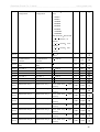
Catalogue
1
2
Safety information and use notice points
1.1
Safety precautions
1.2
Use range
1.3
Use notice points
1.4
Scrap notice points
Type and specification of the inverter
2.1
Incoming inverter inspect
2.2
Type explanation
2.3
Series type explanation
2.4 Appearance and parts name explanation
3
2.5
Outer size and gross weight
2.6
Outer size of keypad and its fixing box
2.7
Product technic index and spec
Installation and wiring
3.1
Installation ambient
3.1.1
Demand for installation ambient
3.1.2
Installation direction and space
3.2
Parts disassembly and installation
3.2.1
Key board disassembly and installation
3.2.2
Cover disassembly and installation
3.3
Wiring notice points
3.4
Main loop terminal wiring
3.4.1
Connection between inverter and fitting parts
3.4.2
Main loop terminal wiring
3.5
Basic running wiring diagram
3.6
Control loop collocation and wiring
3.6.1
Location&function of terminal and jump-wire
3.6.2 Explanation for control CPU board
3.6.3 Analog input output terminal wiring
3.6.4 Communication terminal wiring
3.7
Installation guide for anti-jamming
3.7.1 Restraining to noise disturbance
3.7.2 Local wiring and earthing
3.7.3 Relation of long-distance wiring and current leak
and the countermeasure
3.7.4
Installation demand for electromagnetic on-off
electronic device
4
Run and operation explanation for inverter
4.1
Running order channels
4.1.2
Frequency-provision channel
4.1.3
Work state
4.1.4
Run mode
4.2
6
Operation and use of key board
4.2.1
Keypad layout
4.2.2
Keypad function description
4.2.3
LED and indicator light
4.2.4
Key board display status
4.2.5
Method for operating keypad
4.3
5
Run of inverter
4.1.1
Inverter electrification
4.3.1
Check before electrification
4.3.2
First electrification
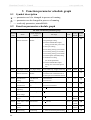
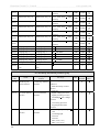
Function parameter schedule graph
5.1
Symbol description
5.2
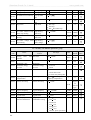
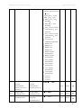
Function parameter schedule graph
Detailed function description
6.1
Basic run function parameter group
F0
6.2
Start-up, shutdown, braking function parameter group
6.3
Auxiliary run function parameter group
6.4
Closed-loop run control parameter group F3
6.5
Simple PLC run function parameter group F4
6.6
terminal function parameter group:F5
6.7
Special parameter for injection molding machine and
F2
constant pressure water supply parameter
6.7.1
Special parameter for injection molding
machine: F6
6.7.2
EDS2800
Constant pressure water supply parameter
group:F6 (EDS2000)
6.8
Traverse special function parameter group F7
6.9
Frequency provision function parameter group
6.10
Protection function parameter: F9
6.11 Failure record function parameter
6.12
7
8
9
F8
Fd
Code and manufacturer function parameter
FF
Troubleshooting
7.1
Failure and countermeasure
7.2
Failure record lookup
7.3
Failure reset
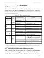
Maintenance
8.1
Routine maintenance
8.2
Inspection and replacement of damageable parts
8.3
Repair guarantee
8.4
Storage
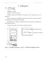
Fitting parts
9.1
LCD keypad
9.2
Brake subassembly
9.2.1
Brake unit
9.2.2
Brake resistance
9.2.3
Configuration
F1
9.2.4
Brake unit outline and assembling dimension
9.2.5
Brake resistance outline and dimension
9.3
10
Communication subassembly
9.3.1
Long-distance operation key board
9.3.2
Communication cable
Examples
10.1
Common speed regulation running
10.2
Terminal control running
10.3
Multi-step speed control running
10.4
Closed-loop control system
10.5
Consecutive action running
10.6
Energy save engineering for injection molding machine
10.7
Constant pressure water supply application
11
12
Serial port (RS485) communication protocol
Use explanation for EDS2860 series
www.gozuk.com
Shenzhen Gozuk Co., Limted
-----------------------------------------------------------------------------------------------------------------------
1
Safety information and use notice points
In order to ensure the safety of your personal and equipment, before using
the inverter, please read this chapter of contents conscientiously.
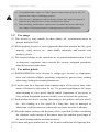
1.1 Safety precautions
There are three kinds of safe relevant warnings in this service manual, they
are as follows:
This symbol briefs on: If does not operate on request, may make the body
!
injured or the equipment damaged.
This symbol is briefed on some useful information.
note
!
This symbol briefs on: If does not operate on request, may cause death,
severely injured or serious property loss.
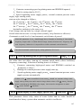
Forbid user directly power off when the inverter is under running, accelerating or
!
decelerating, must only ensure that the drive has been completely shut down or in
standby situation can perform power off operation. Otherwise, the users themselves
afford the damage of the inverter, equipment damage and personal.
(1) Forbid to connect U, V, W output end to AC power supply, otherwise cause the
complete damage of the inverter.
(2) Don't make P- and P + short-circuited, otherwise cause the inverter to be damaged.
(3) The inverter is forbidden to install on the flammables, otherwise have danger of fire.
(4) Don't install it in the environment with explosive gas, otherwise have danger of
causing explosion.
(5) After connecting main loop, should carry on insulating treatment to bare wiring end,
otherwise have danger of getting an electric shock.
!
(6) If being connected to the power supply, don't operate the inverter with moist hands,
otherwise have danger of getting an electric shock.
(7) The ground terminal of the inverter must be grounded well.
(8) Inverter being connected to power supply, please don't open cover and carry on
wiring, can connect the wire or check only after closing power for10 minutes.
(9) Only qualified personnel may carry on wiring and forbid leaving over any
conductive thing in machine, otherwise have danger of getting an electric shock or
causing damage of the inverter.
(10) Inverter stored for over 2 years, should be stepped up gradually with voltage
regulator first while having the electricity, otherwise have danger of getting electric
shock and explosion.
1
Shenzhen Gozuk Co., Limted
www.gozuk.com
----------------------------------------------------------------------------------------------------------------------(1) It is prohibited that connect AC 220V signal to control ends except TA, TB, TC,
otherwise have danger of damaging property.
!
(2) If the inverter is damaged or without all parts, please don't install and operate it,
otherwise have danger of fire or cause personnel to be injured.
(3) When installing, should choose a place where can endure the inverter, otherwise
have danger of injuring personnel or damaging property while falling down.
1.2
Use range
(1) This inverter is only suitable for three phases AC asynchronous motor in
general industrial field.
(2) While applying inverter to such equipments that relate much to the life, great
property, safety devices etc., must handle cautiously, and consult with
producer, please.
(3) This inverter belongs to the control device of general industrial motor, if used
in dangerous equipment, must consider the security safeguard procedures
when the inverter breaks down.
1.3
Use notice points
(1) EDS2000/EDS2800 series inverter is voltage-type inverter, so temperature,
noise and vibration slightly increasing compared to power source running
when using, belongs to normal phenomenon.
(2) If need to run for a long time with constant torque of low-speed, must select
motor of frequency conversion for use. Use general asynchronous AC motor
when running at a low speed, should control temperature of the motor or
carry on heat dissipation measure forcedly, so as not to burn the generator.
(3) Such mechanical device needing lubricating as the gearbox and gear wheel,
etc., after running at a low speed for a long time, may be damaged as
lubrication result become poor, please take necessary measure in advance.
(4) When the motor running with frequency above specified, besides considering
the vibration, noise increase of the motor, must also confirm speed range of
the motor bearing and the mechanical device.
(5) For hoist and great inertia load, etc., the inverter would shut off frequently due
2
Shenzhen Gozuk Co., Limted
www.gozuk.com
-----------------------------------------------------------------------------------------------------------------------
to over-current or over-voltage failure, in order to guarantee normal work,
should consider choosing proper brake package.
(6) Should switch on/off the inverter through terminal or other normal order
channels. It is prohibited that switch on/off the inverter frequently by using
strong electric switch such as magnetic control conductor, otherwise will
cause the equipment to be damaged.
(7) If need to install such switch as the magnetic control conductor, etc. between
inverter output and the motor, please guarantee the inverter is switched on/off
without output, otherwise may damage the inverter.
(8) The inverter may meet with mechanical resonance of the load within certain
range of frequency output, can set up jumping frequency to evade.
(9) Before using, should confirm the voltage of the power is within the working
voltage range allowed, otherwise should vary voltage or order special inverter.
(10) In the condition of altitude above 1000 meters, should use the inverter in
lower volume, reduce output current by 10% of specified current after each
1500 meters height increasing.
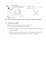
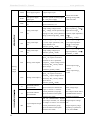
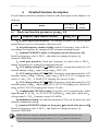
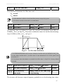
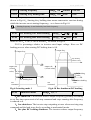
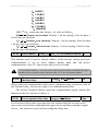
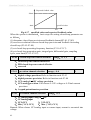
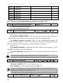
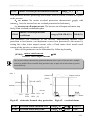
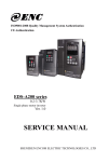
(11) Should make insulation check to the motor before using it for the first time
or after a long time placement. Please inspect with 500V voltage-type
megohm meter according to method shown as graph 1-1 and insulation
resistance should not be smaller than 5 M
, otherwise inverter may be
damaged.
(12) To forbid assembling capacitor for improving power factor or lightningproof
voltage-sensible resistance etc., otherwise will cause malfunction trip of the
inverter or damage of the parts, shown as graph 1-2.
3
Shenzhen Gozuk Co., Limted
www.gozuk.com
----------------------------------------------------------------------------------------------------------------------EDS2000/EDS2800
After wiring, short-circuit U,V, W
to measure insulation resistance.
U
VW
U
EDS2000/ V
EDS2000
EDS2800 W
M
motor
Grounding body
Megohm meter
Fig.1-1 motor insulation measure
Fig.1-2 capacitor at output side forbidden
1.4 Scrap notice points
When disposing scrap inverter and its parts, please note:
(1)
The unit: please discard as industrial useless.
(2)
Electrolytic capacitor: when burning the inverter electrolytic capacitor
in it may explode.
(3)
Plastic: when plastic, rubber parts etc. in the inverter are burning, they
may bring bad, poisonous gas, so please be ready to safeguards.
4
Shenzhen Gozuk Co., Limted
www.gozuk.com
-----------------------------------------------------------------------------------------------------------------------
2
Type and specification of the inverter
2.1 Incoming inverter inspect
(1) Check if there is damage during transportation and inverter itself has damage or
fall-off parts.
(2) Check if parts presented in packing list are all ready.
(3) Please confirm rated data of the inverter is in line with your order requirement.
Our product is guaranteed by strict quality system during manufacturing, packing,
transportation etc., please contact our company or local agent rapidly if some
careless omission or mistake arise, we’ll deal with it as soon as possible.
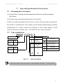
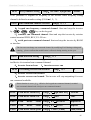
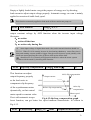
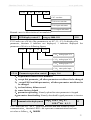
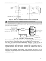
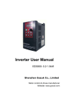
2.2 Type explanation
EDS2000– 4 T 0750 G / B
Inverter serial no.
Volt. grade
code
380V
4
code
General
Fan&pump
code
Input volt.
Code
Three phase
T
Inverter type
Fig. 2-1
Motor power
(KW)
0750
0900
75
90
4000
400
code
Fitting part
built-in brake unit
built-in brake unit
&brake resistance
with LCD
remote-control keypad
type description
If the inverter hasn’t relevant content or can be defaulted, code after “/” will be ignored.
note
5
Shenzhen Gozuk Co., Limted
www.gozuk.com
-----------------------------------------------------------------------------------------------------------------------
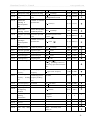
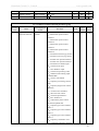
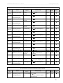
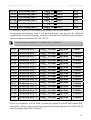
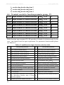
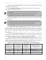
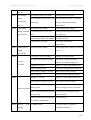
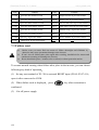
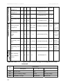
2.3 Series type explanation
Table 2-1 series type explanation
Inverter type
G: general with constant torque; P: special for blower water pump
Rated
power
KVA
Rated output
current A
Adapted
motor
K
——
EDS2800-4T0110G/0150P
17/21.7
25/33
11/15
——
EDS2800-4T0150G/0185P
21.7/25.7
33/39
15/18.5
——
EDS2800-4T0185G/0220P
25.7/29.6
39/45
18.5/22
——
EDS2800-4T0220G/0300P
29.6/39.5
45/60
22/30
——
EDS2800-4T0300G/0370P
39.5/49.4
60/75
30/37
——
EDS2800-4T0370G/0450P
49.4/60
75/91
37/45
——
EDS2800-4T0450G/0550P
60/73.7
91/112
45/55
——
EDS2800-4T0550G/0750P
73.7/99
112/150
55/75
EDS2000-4T0750G/0900P
——
99/116
150/176
75/90
EDS2000-4T0900G/1100P
——
116/138
176/210
90/110
EDS2000-4T1100G/1320P
——
138/167
210/253
110/132
EDS2000-4T1320G/1600P
——
167/200
253/304
132/160
EDS2000-4T1600G/2000P
——
200/250
304/380
160/200
EDS2000-4T2000G/2200P
——
250/280
380/426
200/220
EDS2000-4T2200G/2500P
——
280/318
426/474
220/250
EDS2000-4T2500G/2800P
——
318/342
474/520
250/280
EDS2000-4T2800G/3150P
——
342/390
520/600
280/315
EDS2000-4T3150G/3550P
——
390/430
600/650
315/355
EDS2000-4T3550G/3750P
——
430/447
650/680
355/375
EDS2000-4T3750G/4000P
——
447/493
680/750
375/400
EDS2000-4T4000G
——
493
750
400
6
Shenzhen Gozuk Co., Limted
www.gozuk.com
-----------------------------------------------------------------------------------------------------------------------
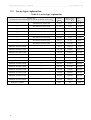
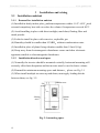
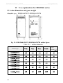
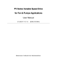
2.4
Appearance and parts name explanation
LCD
LED display
(nonstandand part)
Keypad
Digitalpotentiameter
Control
Namplate
cable inlet
Venthole
Bottom mountinghole
Power input
Inverter output terminal
Fig. 2-3 Parts name sketch
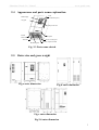
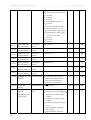
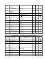
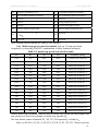
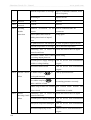
2.5
Outer size and gross weight
Fig.a outer dimension
Fig.b outer dimension
Fig.c outer dimension
Fig.2-4 outer dimension
7
Shenzhen Gozuk Co., Limted
www.gozuk.com
-----------------------------------------------------------------------------------------------------------------------
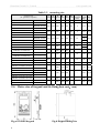
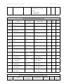
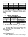
Table 2-2
mounting size
——
Fixing Gross
A
B
W
H
D
D1
Aperture weigth Fig.
(mm) (mm) (mm) (mm) (mm) (mm)
(mm)
(kg)
EDS2800-4T0110 140 350 230 370 212 223
7
14.5 Fig.a
——
EDS2800-4T0150
——
EDS2800-4T0185 180
——
EDS2800-4T0220
——
EDS2800-4T0300
——
EDS2800-4T0370
——
EDS2800-4T0450
——
EDS2800-4T0550 250
Inverter type
(G: general; P: special)
EDS2000-4T0750G/4T0900P
——
EDS2000-4T0900G/4T1100P
——
EDS2000-4T1100G/4T1320P
——
EDS2000-4T1320G/4T1600P
——
EDS2000-4T1600G/PA
——
EDS2000-4T2000G/PA
——
EDS2000-4T2200G/PA
——
EDS2000-4T2500G/PA
——
EDS2000-4T2800G/PA
——
EDS2000-4T1600G/4T2000P
——
EDS2000-4T2000G/4T2200P
——
EDS2000-4T2200G/4T2500P
——
EDS2000-4T2500G/4T2800P
——
EDS2000-4T2800G/4T3150P
——
EDS2000-4T3150G/4T3550P
——
EDS2000-4T3550G/4T3750P
EDS2000-4T3750G/4T4000P
——
EDS2000-4T4000G
——
2.6
260
460
252
261
9
18.5
Fig.a
515
300
535
252
261
9
25.5
Fig.a
52
620
370
645
258
267
12
52
Fig.a
53
300
650
480
680
360
369
12
84
95
Fig.a
400
720
480
750
372
381
12
400
740
480
770
410
—
12
98
104
420 1157 560 1200 430
—
14
165
Fig.c
500 1157 660 1200 430
—
14
190
Fig.c
—
—
600 1500 500
—
—
165
Fig.b
—
—
600 1600 500
—
—
195
Fig.b
—
—
700 1600 500
—
—
225
Fig.b
—
—
800 1750 550
—
—
250
Fig.b
—
—
900 1800 600
—
—
275
Fig.b
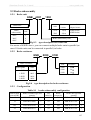
Outer size of keypad and its fixing box (unit mm)
Fig.a EN-KB1 keypad
8
——
200
440
Fig.b keypad fitting box
Fig.a
Fig.a
Shenzhen Gozuk Co., Limted
www.gozuk.com
-----------------------------------------------------------------------------------------------------------------------
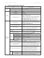
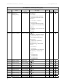
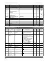
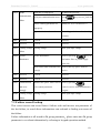
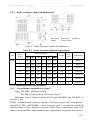
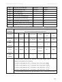
2.7
Product technic index and spec
Item
Item description
Rating volt., frequency
3 phase 380V 50Hz/60Hz
Input
Allowed work volt. range
Voltage
Frequency
Volt. 320V~460V
0-380V
0Hz-400Hz
Over loading capacity
G type: 150% of rated current for 1 minute 200%
of rated current for 0.5s
P type: 90KW~132KW: 120% of rated current for
1 minute 160KW above: 110% of rated current
for 1 minute 150% of rated current for 1s
EDS2800/EDS2860 type: 150% of rated current
for 3 minutes 200% of rated current for 5s
Control mode
optimized space volt. vector PWM control mode for
EDS2000; simple current vector control mode for
EDS2800 and EDS2860 series
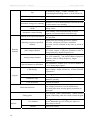
output
Speed regulation range
Start-up torque
Running speed stable state
precision
Frequency precision
Frequency
Control resolution
performance
1
100
150% of rating torque at 3 Hz frequency for
EDS2000 series; 130% of rated torque at 1Hz
frequency for EDS2800 and EDS2860 series
0.5% of rating synchronous speed
Digital setting: max. frequency
0.01% analog
setting: max.frequency
0.5%
Analog setting
0.1% of max. frequency
Digital setting
0.01Hz
Exterior impulse
Keypad digital
setting
Torque boost
V/F curve (volt. frequency
characteristic)
0.1% of max. frequency
0.01Hz
Automatic torque boost manual torque boost
0.1%~20.0%
Set rating frequency randomly at range of
5~400Hz can choose constant torque, degressive
torque 1, degressive torque 2, degressive torque 3,
user defined V/F curve in total 5 kinds of curve
3 modes straight line accelerating decelerating, S
curve accelerating decelerating and automatic
Accelerating decelerating curve accelerating decelerating mode; 4 kinds of
accelerating decelerating time (unit minute/second
can be optioned), max. time 6000 minutes.
Powerconsumption brake Interior or exterior brake resistance
brake
DC brake
Optional start-up and stop action frequency 0~15Hz
action volt. 0~15% action time 0~20.0 s
9
Shenzhen Gozuk Co., Limted
www.gozuk.com
----------------------------------------------------------------------------------------------------------------------Jog
Jog frequency range 0.50Hz~50.00Hz; jog
accelerating decelerating time 0.1~60.0s can be set
Multisection speed running
Realized by interior PLC or control terminal
Interior PID controller
Be convenient to make closed-loop system
Optimize V/F curve automatically based on the load
to realize power save running
Automatic volt. regulation
Can keep constant output volt. When power source
(AVR)
voltage varies.
Limit running current automatically to avoid
Automatic current limiting
frequent over-current which will cause trip
Key pad specified, control terminal specified, serial
Running order specified channel
port specified
Digital provision, analog provision, impulse
Running frequency specified Provision, serial port provision, combined
channel
Provision, can be switched at any time by kinds of
method
Automatic energy save running
Running
function
pulse output channel
Analog output channel
Special channel for EDS2800
keypad
LED display
Can display setting frequency, output frequency,
output voltage, output current etc. in total 20 kinds
of parameter
LCD display
optional
Parameter copy
Lock the button
Lock all the button
Fitting parts
Use ambient
altitude
10
operation is noted by English
Use keypad and remote-control keypad to copy the
parameter speedily
Protection function
ambient
Impulse square wave signal output of 0~50KHz
can realize output of physical parameter such as
setting frequency, output frequency etc.
2 channel of analog signal output optional 4~20mA
or 0~10V separately can realize output of physical
parameter such as setting frequency, output
frequency etc.
Inter-insulated 2 channel of 0~1A and 2 channel of
0~10V analog input signal
Over-current protection, over-voltage protection,
lack-voltage protection, over-heat protection,
over-load protection, missing phase protection (in
option)etc.
LCD keypad, brake subassembly, remote-control
keypad, connecting cable for remote-control keypad
etc.
indoor not bare to sunlight no dust, no corrosive
gas, no flammable gas, no oil fog, no vapor, no
water drop or salt etc.
Lower than 1000m
Shenzhen Gozuk Co., Limted
www.gozuk.com
-----------------------------------------------------------------------------------------------------------------------
Ambient temperature
Ambient humidity
vibration
Storage temperature
configuration
Defending grade
Cooling mode
Mounting mode
-10ºC~+40ºC(under ambient temperature 40ºC
~50ºC, please reduce the volume or strengthen heat
sink)
Smaller than 95%RH, no condensation water
Smaller than 5.9m/s²(0.6g)
-40ºC~+70ºC
IP20
By fan with automatic temperature control
Wall hanging for type of 132kwG/160kWP and
below, cabinet standing for type of
160kwG/200kwP and above, wall hangning for all
EDS2800 types.
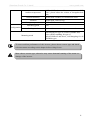
note
To exert excellent performance of this inverter, please choose correct type and check
relevant content according to this chapter before wiring for use.
!
Must choose correct type, otherwise may cause abnormal running of the motor or
damage of the inverter.
11
Shenzhen Gozuk Co., Limted
www.gozuk.com
-----------------------------------------------------------------------------------------------------------------------
3
3.1
3.1.1
Installation and wiring
Installation ambient
Demand for installation ambient
(1) Installed in drafty indoor place ambient temperature within -10 ºC~40ºC need
external compulsory heat sink or reduce the volume if temperature exceeds 40ºC.
(2) Avoid installing in place with direct sunlight, much dust, floating fibre and
metal powder.
(3) Forbid to install in place with corrosive, explosible gas.
without condensation water.
(4) Humidity should be smaller than 95%RH
(5) Installed in place of plane fixing vibration smaller than 5.9m/s²(0.6g).
(6) Keep away from electromagnetic disturbance source and other electronic
apparatus sensible to electromagnetic disturbance.
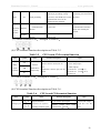
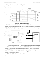
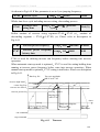
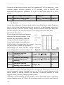
3.1.2
Installation direction and space
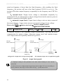
(1) Normally the inverter should be mounted vertically, horizontal mounting will
seriously affect heat dissipation and the inverter must be used in lower volume.
(2) Demand for minimum mounting space and distance
please see Fig.3-1.
(3) When install multiple inverters up and down, must apply leading divider
between them, see fig. 3-2.
Fan
exaust
200mm more
500mm
more
500mm
more
200mm more
Fig. 3-1 mounting space
12
Shenzhen Gozuk Co., Limted
www.gozuk.com
-----------------------------------------------------------------------------------------------------------------------
Fig. 3-2 mounting of multiple inverters
3.2
Parts disassembly and installation
3.2.1 Key board disassembly and installation
(1) disassembly
Let the forefinger press finger inlet on the keypad depress fixing flexible plate
on the top lightly, draw it outward, then you can disassemble the keypad.
(2) assembly
First place the fixing hook at the bottom of keypad onto mounting claw on
keypad mounting hole, let forefinger press fixing flexible plate on top of
keypad and then push it inside, release it in proper location(after a crisp sound),
see fig. 3-3.
Mounting claw
Hook
Mounting claw
Fig.3-3 mounting sketch of keypad
13
Shenzhen Gozuk Co., Limted
www.gozuk.com
-----------------------------------------------------------------------------------------------------------------------
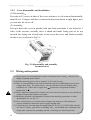
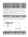
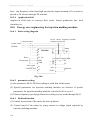
3.2.2 Cover disassembly and installation
(1) Disassembly
First take off 2 screws at sides of the cover and move it a bit outward horizontally,
then tilt it at 15 degree and draw it outward at direction shown in right figure, now
you can take the cover off.
(2) Assembly
First put down the cover in parallel with unit body and make it just locked at 2
sides of the inverter, secondly force it ahead and make fixing part on its top
inserted into fixing slot of unit body, at last screw the cover and finish assembly
for the cover. As shown in Fig.3-5.
Fig. 3-5 disassembly and assembly
for metal cover
3.3
Wiring notice points
(1) Assure power cut off completely for above 10 minutes before wiring otherwise have
danger of getting electric shock.
(2) Forbid connecting power wire to output U, V, W of the inverter.
(3) There is current leakage in the inverter and leak current of middle/high power inverter
is bigger than 5mA for safety reason inverter and motor must be earthed safely
commonly use 3.5mm² above copper wire
ground wire and ground resistance
smaller than 10 .
(4) Before shipment compression resistance test of the inverter is passed so user should not
conduct compression resistance test again.
(5) Should not assemble electromagnetic contactor and absorbing capacitance or other
absorbing device, see fig. 3-5.
(6) To be convenient to over current protect of input side and power off maintenance
inverter should be connected to power supply through relay.
(7) Connecting wire for relay input and output loop(X1~X8, Y1, Y2, FWD, REV), should
use above 0.75mm glued wire or shielding wire one shielding layer end hung in the
air,the other connected to grounding end PE, connecting wire shorter than 50m.
!
14
Shenzhen Gozuk Co., Limted
www.gozuk.com
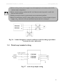
----------------------------------------------------------------------------------------------------------------------(1)Before wiring, assure power supply is cut off completely for 10 minutes and all LED
indicator light extinguished.
!
(2)Before internal wiring, confirm that DC volt. Between main loop end P+ and P- fall
down to below DC36V.
(3)Wiring can only be done by professional person trained and qualified.
(4)Before electrification, check if voltage grade of the inverter is in line with that of power
supply volt.
otherwise will cause personnel injured and device damaged.
EDS2000/
EDS2800
Fig.3-6
U
V
M
W
banned magnetic control conductor and absorbing capacitance
between inverter and motor
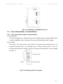
3.4 Main loop terminal wiring
3 phase breaker
3 phase
AC power
supply
Fig.3-7
R
S
T
EDS2000/
EDS2800/
EDS2860
U
V
W
PE
M
main loop simple wiring
15
Shenzhen Gozuk Co., Limted
www.gozuk.com
-----------------------------------------------------------------------------------------------------------------------
3.4.1 Connection between inverter and fitting parts
(1) Must assemble disjunction
R
S
device such as isolation switch etc. T
N
between powersource and the
inverter to assure personal safety
Isolation switch
when repairing the inverter and
needing compulsory power off.
Breaker or fuse
(2) Power supply loop must have
breaker or fuse with over current
AC input reactor (in option)
protectionfunction to avoid
malfunction expandingcaused
Magnetic control conductor
by failure of after device.
(3) AC input reactor
Input EMI filter (in option)
If high-order harmonics between
inverter and power supply is biggish
R S T
DC output reactor(in option)
which cant fulfil system requirement
EDS2000/
Brake unit (in option)
or need to improve input side power
EDS2800
factor, AC input reactor is needed.
PE U V W
Brake resistance (in option)
(4) Magnetic control conductor only be
applied to power supply control and
Output EMI filter (in option)
dont apply magnetic control
conductor to controlling on/off of
AC output reactor(in option)
the inverter.
(5) Input side EMI filter
M
Can use EMI filter to inhibit
high-frequency conduction
disturbance and emission
Fig.3-8 the connection betweem the
disturbance from inverter power
inverter and fittings parts
supply wire.
(6) DC reactor
Built-in DC reactor as standard configuration for EDS2000-4T1600G/4T2000P
and type of higher power, put-outside DC reactor as fitting part for type of power
lower than EDS2000-4T11600G/EDS2000-4T1600P. To avoid effect tothe
inverter from power supply and to protect the inverter and to inhibit high order
harmonic, should deploy DC reactor under following situations.
When there is on-off blind power compensation capacitor or controlled silicon
16
Shenzhen Gozuk Co., Limted
www.gozuk.com
-----------------------------------------------------------------------------------------------------------------------
phase control load at the same power supply for the inverter, its possible to
damage input rectifying circuit of the inverter because on/off switching of
capacitor may causesudden change of power network voltage and phase control
load cause harmonic and power network wave-form aberration.
When unbalance degree of 3 phase power supply for the inverter exceeds 3%.
When input side power factor of the inverter is required to reach above 0.9.
Under normal situation, DC reactor is needed for the inverter when
capacitance of power supply is larger than 10 times of inverter capacitance.
(7) Output side EMI filter
Can use EMI filter to inhibit emission disturbance noise and wire leakage current
from output side.
(8) AC output reactor
Advise assembling AC output reactor to avoid motor insulation damage, too large
over current and inverter frequent protection when connecting wire from inverter
to motor exceeds 50m.But voltage drop of AC output reactor must be considered.
Improve input output voltage of the inverter or let the motor in lower volume to
avoid burning off the motor.
(9) Complete ground wire
Inverter and motor must be earthed and grounding resistor smaller than 10 .
Grounding wire should be shorter enough and wire diameter be bigger
enough(not smaller than following standard):
75KW and above motor 38mm² above copper wire
17
Shenzhen Gozuk Co., Limted
www.gozuk.com
-----------------------------------------------------------------------------------------------------------------------
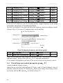
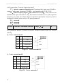
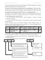
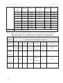
3.4.2 Main loop terminal wiring
For main loop input output terminal, see table 3-1.
Table 3-1 main loop input output terminal description
Adapted type
EDS2800-4T0110
Main loop terminal
Terminal
name
3 phase AC 380V input
terminal
DC side voltage positive
terminal P, P+ can connect
DC reactor
DC side voltage negative
terminal
DC braking resistance can
be connected between P
and PB
3 phase AC output
terminal
Shield grounding terminal
R S T P P+PB P- U V W E
R, S, T
EDS2000-4T0750G~
P
EDS2000-4T3750G
EDS2000-4T0900P~
EDS2000-4T3750P
R S T P P+ P- U V W E
P+
P-
EDS2800-4T0150~
EDS2800-4T0550
Function description
U,V, W
E
3 phase AC 380V input
terminal
DC side voltage positive
terminal
Reserved terminal for
exterior DC reactor
DC side voltage negative
terminal
3 phase AC output
terminal
Shield grounding terminal
(1) Can connect braking unit between P+ and P- externally if necessary.
note
18
(2) Can connect DC braking resistor between PB and P+ externally if necessary.
(3) DC ractor can be connected between P and P+ if necessary.
(4) P and P+ must be short-circuited before shipment, otherwise the inverter cant work.
Shenzhen Gozuk Co., Limted
www.gozuk.com
-----------------------------------------------------------------------------------------------------------------------
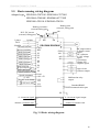
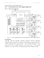
3.5
Basic running wiring diagram
Adapted type EDS2000-4T0750G~EDS2000-4T3750G
EDS2000-4T0900P~EDS2000-4T3750P
EDS2800-4T0110~EDS2800-4T0550
Braking unit
(external, fitting part)
Braking resistance
(external,fitting part
DCL DC reactor
(external, fitting part)
breaker
3 phase
380V
50/60Hz
Forward run/stop
Reverse run/stop
Multi-function1
Multi-function2
Multi-function 3
p
R
Multi-function 4
Multi-function 5
Multi-function 6
Multi-function 7
(H-speed impulse input
Multi-function 8
(H-speed impulse input
Speed command
0~10V
0~10V or 4~20mA
0~5V or 0~10V
P+
PB
P-
U
S EDS2000/EDS2800 V
W
T
FWD
E
REV
GND
A01
X1
X2
A02
X3
DO
X4
X5
COM
X6
Y1
X7
Y2
X8
COM
+10V/+5V
VCI
CCI
YCI
GND
M
DC amperometer
4-20mA current
signal
DC voltmeter
0~10V voltage
signal
Cymometer
Output 24V
impulse signal
open circuit
collector output
CME
+
TA
Malfunction relay
TB output
TC
Standard RS485
RS485+
communication port
RS485PE
0~1Acurrent signal
channel 1 common end
1I
2I
1C
2C
0~1Acurrent signal output
channel 2 common end
Fig. 3-9 Basic wiring diagram
19
Shenzhen Gozuk Co., Limted
www.gozuk.com
-----------------------------------------------------------------------------------------------------------------------
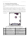
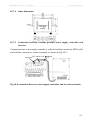
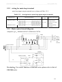
3.6 Control loop collocation and wiring
3.6.1
Location&function of terminal and jump-wire
For location of terminal and jumping-wire switch on the CPU board, please see
Fig.3-9.
Function description of terminal provided for the user, please see Table 3-2
function and setup description of jumping-wire switch, please see Table 3-3
terminal CN1, CN2 and CN4 are for manufacturers use. Should carry on terminal
wiring correctly and set all jumping-wire switch on the CPU board before using
the inverter to use 1mm² above conducting wire as terminal connecting wire is
recommended.
CN1
CN4
CN2
CN6
JP7 JP1
YCI JP2
AO2 AO1
+5V +5V
CN8
CCI
JP4 JP5
TA TB TC
CN5
Fig. 3-10 jumping-wire switch on CPU board
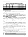
Table 3-2 function description of terminal provided for user
symbol
20
function
Description
CN3
RS485 communication port
Remote-control keypad and upper machine
control connection port
CN5
Malfunction relay signal output
Always-open connect pin of the relay closed
when malfunction in inverter occurs
CN6
External terminal input output control
Use this port when external terminal control
inverter running
CN8
Special channel for injection molding
machine
Special input channel for EDS2800 series
Shenzhen Gozuk Co., Limted
www.gozuk.com
-----------------------------------------------------------------------------------------------------------------------
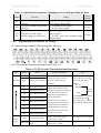
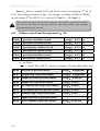
Table 3-3 function description of jumping-wire switch provided for user
symbol
JP1
JP2
JP4
JP5
3.6.2
factory
default
function
setting
YCI 5V/10V voltage input mode
selection
CCI current/voltage input mode
selection
2 group of separate analog output
terminal AO1, A02 output
current/voltage type selection
5V 0-5V voltage signal
10V 0-10V voltage signal
A 0/4~20mA current signal
V 0~10V voltage signal
A 4~20mA AO1, AO2 terminal output
current signal
V 0~10V AO1, AO2 terminal output
voltage signal
0-5V
0~10V
0~10V
Explanation for control CPU board
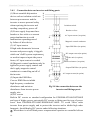
(1) control loop terminal CN6 arranged as follows
(2) CN6 terminal function description as Table 3-4.
Table 3-4 CPU board CN6 terminal function table
item
symbol
name
REV
Reverse run command three-wire control function
F5.08 group double-wire and
description
X1
X2
X3
X4
X5
X6
Power
supply
Spec
Forward run command Forward reverse run command, see Optocoupler isolation input
run
command
Function description
FWD
200Hz
X1~X8
FWD, REV
Multi-function input 1
Used for multi-function input
Close
Multi-function input 2 terminal, for detailed see Chapter 6
effect
Section 6.6 terminal function
COM
Multi-function input 3
parameter(F5 group)input end
Input impedance of X7, X8
Multi-function input 4 function description.
input channel:R=2K
X7, X8 can be set as H-speed
Max. output Freq.: 50KHz
Multi-function input 5 pulse input port, for detailed see
Input voltage range:15~24V
Multi-function input 6 Chapter 6 Section 6.6 terminal
X7
function parameter (F5 group)
Multi-function input 7 input end function description.
X8
Multi-function input 8
+24V
+24V power supply
+10V/+5V
Input impedance: R=2K
Max. input frequency:
(common end: COM)
Provide +24V power supply.
(negative pole
Max. output current:150mA
COM)
+10V/+5V power
Provide +10V/+5V power supply.
supply
(negative pole
Max. output current:50mA
GND)
21
Shenzhen Gozuk Co., Limted
www.gozuk.com
-----------------------------------------------------------------------------------------------------------------------
COM
Common end+24V
Common end and reference ground
power supply negative
of digital signal input
pole
GND
CME
Internal one another
+10V power supply
Reference ground of analog signal
isolating among CME,
negative pole
and +10V power supply
COM and GND
Y1, Y2output common Common end of multi-function
end
output terminal Y1, Y2
Input voltage range 0~10V
Accept analog voltage/current
CCI
(input impedance
70K )
Analog value input
input voltage, current optioned by Input current range
CCI
jumping-wire JP2 factory default is 4~20mA (input impedance
voltage. (reference ground
GND) 250 )
Resolution
1/1000
Accept analog voltage input,0~5V Input voltage range
YCI
VCI
Analog value input
or 0~10V input optioned by JP1
0~5V(input impedance
YCI
factory default 0~5V
70K ), 0~10V(input
(reference ground
impedance 36K )
GND)
Analog value input
Accept analog voltage input
VCI
(reference ground
GND)
Input voltage range 0~10V
(input impedance
resolution
70K )
1/1000
Provide analog voltage/current
output can express 6 kinds of
parameter see F5.17 parameter
AO1
Analog value output1 description
output voltage/current
optioned by JP4 factory default
output voltage.
Analog
(reference ground
value
output
GND)
Provide analog voltage/current
output can express 6 kinds of
AO2
Analog value output 2
parameter
Current output range
4~20mA
voltage output range
0~10V
output voltage/current
optioned by JP5 factory default
output current.
(reference ground
Y1
Y2
GND)
Open circuit collector
Used for multi-function switch
optocoupler isolation output
output terminal 1
output terminal, for detailed see
Work voltage range:
Chapter 6 Section 6.6 terminal
15~30V
Open circuit collector
function parameter (F5 group)
Max. output current:50mA
output terminal 2
output end function description.
Use method see F5.10~F5.11
(common end: CME)
description of parameter
Used for multi-function impulse
signal output terminal, for detailed Output impulse voltage:
DO
22
H-speed impulse output
terminal
see Chapter 6 Section 6.6 terminal 24V
function parameter(F5 group)
Output frequency range:
output end function description.
depending on parameter
(common end: CME)
F5.23, max.50KHz
Shenzhen Gozuk Co., Limted
www.gozuk.com
-----------------------------------------------------------------------------------------------------------------------
shield
PE
Used for terminal connecting wire
Connect with mail loop
shield layer grounding, analog
connecting wire terminal E
signal wire, 485 shield layer of 485 interiorly
Shield grounding
communication wire can be
connected to this terminal
RS485+
communic
RS485+
ation
communication
485 difference signal
For standard RS-485
positive end
communication interface
please use twisted-pair
interface
or STP
interface
RS485-
RS485- communication 485 difference signal
interface
negative end
(3) control terminal CN5
arranged as follows
(4) CN5 terminal function description as Table 3-5.
Table 3-5
Item
symbol
name
Function description
Spec
TB-TC: always-closed,
TA
Relay
output
CPU board CN5 terminal function
Inverter
TB
malfunction
terminal
output relay
TC
Normal: TB-TC closed, TA-TC
TA-TC: always-open
open
Contact capacity:
Malfunction: TB-TC open, TA-TC
AC250V/2A (COS
=1)
closed
AC250V/1A (COS
=0.4)
DC30V/1A
(5) control terminal CN8
arranged as follows
(6) CN8 terminal function description as Table 3-6.
Table 3-6
Item
symbol
1I
Analog input
2I
1C 2C
CPU board CN8 terminal function
name
Function description
Special channel 1,
0~1A current input signal
channel 2 for injection
Current, voltage input signal
molding machine signal
common end
ground
Spec.
Current and voltage
signal dont use the
same
23
Shenzhen Gozuk Co., Limted
www.gozuk.com
-----------------------------------------------------------------------------------------------------------------------
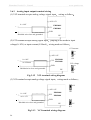
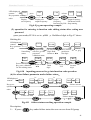
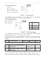
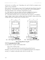
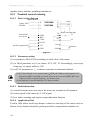
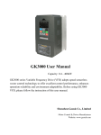
3.6.3
Analog input output terminal wiring
(1) VCI terminal accepts analog voltage signal input
wiring as follow
+10V/+5V
0~+10V
+
VCI
EDS2000/
EDS2800
GND
Shielded wire close end grounded
Fig.3-11
PE
VCI terminal wiring diagram
(2) CCI terminal accepts analog signal input jumping-wire decide to input
voltage(0~10V) or input current(4~20mA) wiring mode as follows
CCI current
A
V
+10V/+5V
+
+
0~+10V
EDS2000/
CCI EDS2800
or 4~20mA
Fig.3-11
CCI terminal GND
wiring diagram
Shielded wire close end grounded
JP2
CCI voltage
A
PE
V
JP2
Fig.3-12
YCI terminal wiring diagram
(3) YCI terminal accepts analog voltage signal input wiring mode as follows
10V
+10V/+5V
+
EDS2000/
YCI EDS2800
0~+10V
or 0~+5V
JP1
GND
Shielded wire close end grounded
5V
PE
JP1
Fig.3-13
24
YCI terminal wiring diagram
Shenzhen Gozuk Co., Limted
www.gozuk.com
-----------------------------------------------------------------------------------------------------------------------
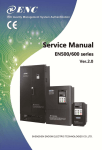
(4) wiring of analog output terminals AO1, AO2
analog output terminals AO1, AO2 connected to analog meter and kinds
of physical data can be indicated, jumping-wire decide to output current (4~20mA)
or voltage (0~10V). Terminal wiring mode as Fig.3-13.
Analog current output
Analog meter
A
A01
V
EDS2000/
A02
EDS2800
Analog voltage output
GND
A
V
A01:JP4
Fig.3-14
A02:JP5
analog output terminal wiring
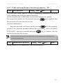
(5) special injection molding machine current switching signal 0~1A corresponds
to 0~10V set frequency. As shown in Fig.3-14
0~1A
1I(2I)
EDS2800A
1C(2C)
Shielded wire close end grounded
Fig.3-15
note
PE
special wiring diagram for injection molding machines
(1) When inputing anglog signal can connect filter capacitor or common module
inductance between VCI and GND or between CCI and GND or between YCI and
GND; between 1I(2I) and 1C(2C) or between 1V(2V) and 1C(2C).
(2) Analog input, output signal is easy to be disturbed so must use shielded cable when
wiring and well grounded, wiring length should be as short as possible.
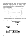
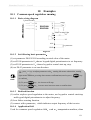
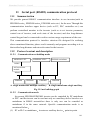
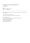
3.6.4
Communication terminal wiring
EDS2000 inverter provides communication interface for the user .Following
25
Shenzhen Gozuk Co., Limted
www.gozuk.com
-----------------------------------------------------------------------------------------------------------------------
wiring methods make single-main single-sub control system or single-main
multi-sub control system possible. Using upper machine(PC or PLC
controller)software can realize real time supervision to inverter in the industrial
control system so that realize complicated run control such as long-distance
control, high automatization etc.
(1) When inverter RS485 interface connected to other devices with RS485
interface , then connect wire as below figure.
A(485+)
1(485+)
EDS2000
Device with
RS485
CN3
B(485 -)
3(485 -)
Fig.3-16
interface
communication terminal wiring
(2) Please follow below figure when connecting remote control keypad .
Notice:
1 No need to set any parameter inverter local keypad and remote control keypad
can work at one time.
2
Users wiring as follow diagram:
EDS2000MPCB23 and higher version
EDS2000-485PPCB21
Fig.3-17
26
remote control keypad wiring
Shenzhen Gozuk Co., Limted
www.gozuk.com
-----------------------------------------------------------------------------------------------------------------------
(3) Multiple inverters can be connected together per RS485 and 31pcs device with
RS485 interface can be connected together at most. Communication system is
more prone to disturbance as connected device increasing, following wiring is
recommended
(fig3-18)
EDS2000
inverter
EDS2000
inverter
EDS2000
inverter
Fig. 3-18 recommended PLC and multiple inverters communication wiring
Normal communication still not available if using above wiring, can try to take
following measure
1> Provide separate power supply for PLC (or upper machine) or isolate its
power supply.
2> Apply magnetic circle on the communication wire.
3> Reduce inverter carrier wave frequency properly.
RS485 interface of EDS2000/EDS2800 can only be used as interface of sub-device
note
3.7
need to set PLC or PC as main unit
please refer to appendix communication protocol.
Installation guide for anti-jamming
Main circuit of the inverter is composed of high-power semiconductor switch
gear so some electromagnetic noise will arise during work to reduce or stop
disturbance to environment show you assembling method of inverter disturbance
suppressing from many aspects such as disturbance suppressing, spot wiring,
system grounding, leak current, usage of power supply filter etc. in this section to
be referred to during spot assembling.
3.7.1 Restraining to noise disturbance
Disturbance brought by the working inverter may affect nearby electronic device
effect degree relates to surrounding electromagnetic environment of the inverter
and anti-disturbance capacity of this device.
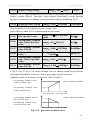
(1) type of disturbance noise
According to work principle of the inverter, there are mainly 3 kinds of noise
27
Shenzhen Gozuk Co., Limted
www.gozuk.com
-----------------------------------------------------------------------------------------------------------------------
disturbance source
2> space emission disturbance
1> circuit conduction disturbance
3> electromagnetic induction disturbance
disturbance
conduction disturbance
Leak current
Power supply wire
grounding loop
high-order
disturbance
harmonic
Road
Space emission disturbance electromagnetic induction disturbance
Input wire
Inverter power
Output wire
induction
parts induction
induction
Road
Road
Road
Emission disturbance of
Emission
Inverter main loop switch
disturbance from
And switching power
Emission disturbance
from power supply
motor wire U, V, W wire R, S, T
supply
Road
Road
Fig.3-19
Road
type of noise disturbance
(2) noise spread road
TV
power supply
sensor
Fig.3-20
28
inverter
Wireless set
meter
moter
noise disturbance spread road sketch
Road
Shenzhen Gozuk Co., Limted
www.gozuk.com
-----------------------------------------------------------------------------------------------------------------------
(3) basic countermeasure for suppressing disturbance
Table 3-8 disturbance suppressing countermeasure table
Noise
spread
Countermeasure of weakening effect
road
When grounding wire of peripheral device and wiring of the inverter compose
closed-loop, inverter grounding wire leakage current would make the device do
wrong action. Can reduce wrong action if the device is not earthed here.
High-order harmonic from the inverter would make voltage and current transmit
through power supply wire when peripheral device and the inverter electrified by
same power supply, would disturb other devices in this same power supply system
can take following suppressing measure
inverter input end
assemble electromagnetic noise filter at
isolate other devices by isolation transformer; connect power
supply for peripheral device with remote power source; install ferrite filter magnetic
circle for R, S, T three-phase conducting wire of the inverter to suppress conduction
of high-frequency harmonic current.
Keep device and signal wire prone to disturbance from the inverter. Should use
shielded signal wire, shielding layer single end earthed and try best to keep away
from the inverter and its input, output wire. If signal wire must intersect strong power
cable, must keep them in real intersection and avoid parallel.
Install high-frequency noise filter(ferrite common module choke, folksay magnetic
circle) separately at input, output root
which can effectively suppress emission
disturbance from dynamic wire.
Should place motor cable shield of biggish thickness, for instance set it in tube
with biggish thickness (above 2mm) or bury it in cement slot. Dynamic wire set into
metal tube and use shielding wire to be grounded (use 4-core motor cable, one side is
earthed through the inverter, the other side connected to motor shell).
To prevent parallel or bundled power and weak conducting wire should keep away
from inverter mounted device to the best and its wiring should keep away from power
wire of the inverter such as R, S, T, U, V, W etc.. Should pay attention to relative
mounting place between device with strong electric field or strong magnetic field and
the inverter, should keep distance and vertical intersection.
29
Shenzhen Gozuk Co., Limted
www.gozuk.com
-----------------------------------------------------------------------------------------------------------------------
3.7.2
Local wiring and earthing
(1) Avoid parallel cable from inverter to motor
Power supply wire or
(U, V, W terminal education wire) and
power supply wire (R, S, T terminal input wire).
motor cable
Control signal cable
Should keep distance of 30cm above.
Fig.3-21 system wiring demand
(2) Try your best to place motor table from U, V, W terminals in metal tube or
metal wiring slot.
(3) Should use shielded cable as common control signal cable
shielding layer
close-toinverter side earthed after connected with PE terminal of inverter.
(4) Cable educed from inverter PE terminal must be connected directly to
earth-plate and cant be connected to ground through grounding wire of other
devices.
(5) Powerful cable(R, S, T, U, V, W)should not parallel control signal cable
closely, say nothing of being bundled together, must keep distance of 20~60cm
above (related to size of powerful current). Should cross each other vertically if
intersection, as Fig.3-19.
(6) Powerful grounding wire must be connected to earth separately from weak
grounding cable such as control signal and sensor cable etc.
(7) Forbid to connect other electricity consumption device to inverter power
supply input end(R, S, T).
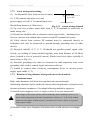
3.7.3
Relation of long-distance wiring and current leak and the
countermeasure
High -order harmonic will form between-line leak current through
distributing capacitor and to-earth leak current when long-distance wiring between
inverter and motor commence. Can adopt following method to suppress
(1) Install ferrite magnetic circle or output reactor at inverter output side.
End voltage of the motor will be reduced markedly when installing reactor of 5%
!
above rated voltage drop and make long-distance wiring to U, V, W. Fully loaded
motor have the danger of burning itself should work in lower volume or step up its
input output voltage.
(2) Reduce carrier wave frequency but motor noise would increase accordingly.
30
Shenzhen Gozuk Co., Limted
www.gozuk.com
-----------------------------------------------------------------------------------------------------------------------
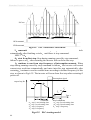
3.7.4
Relay
Installation demand for electromagnetic on-off electronic device
magnetic control conductor and electromagnetic iron and so on, these
electromagnetic on-off electronic device would bring lots of noise during work, so
you should pay full attention to when installing them beside the inverter or in the
same control chamber with the inverter and must install surge absorbing device as
shown in Fig. 3-22.
diode
+
220VDC
_
Voltage-sensible resistor
Inverter or
other electric
220VAC
apparatus
RC-filter
220VAC
Fig.3-22
installation demand for electromagnetic on-off device
31
Shenzhen Gozuk Co., Limted
www.gozuk.com
-----------------------------------------------------------------------------------------------------------------------
4
Run and operation explanation for inverter
4.1 Run of inverter
4.1.1
Running order channels
There are 3 kinds of order channel for controlling run action of the inverter such
as run, stop, jog etc.
0
keypad
Control by key
,
,
on keypad(factory default).
1: control terminal
Use control terminal FWD, REV, COM to make of double-line control
or
use one terminal of X1 X8 and FWD or REV to make of three-line control.
2
serial port
Control run and stop of the inverter through upper machine or other device
which can communicate with the inverter.
Choose order channel by setting function code F0.02 and also can choose by
multi-function input terminal(F5.00~F5.07 choose 27, 28, 29 function).
Please make switching debugging in advance when switch the order channel to check if
!
it can fulfil system requirement otherwise have danger of damaging device and injuring
personal.
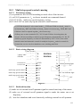
4.1.2
Frequency-provision channel
Under EDS2000/EDS2800 common run mode there are 9 kinds of provision
channel
32
0
keypad digital potentiometer provision
1
direct digital frequency provision
2
terminal UP/DOWN provision
3
serial port provision
4
analog value VCI provision
5
analog value CCI provision
6
analog value YCI provision
7
terminal pulse(PULSE) provision
8
combination set.
Shenzhen Gozuk Co., Limted
www.gozuk.com
-----------------------------------------------------------------------------------------------------------------------
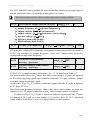
4.1.3
Work state
Work state of EDS2000/EDS2800 is classified as waiting state and running state
waiting state If there is no running command after the inverter electrified or after
stop command during running state, the inverter enters into waiting state.
running state the inverter enters into running state after receiving run command.
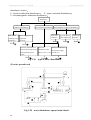
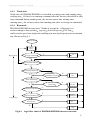
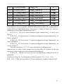
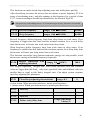
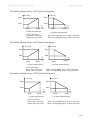
4.1.4 Run mode
EDS2000/EDS2800 inverter have 7 kinds of run mode following is in
turn according to their priority jog run closed-loop run PLC run
multi-section speed run injection molding run swing frequency run common
run. Shown as Fig.4-1
Electrification
waiting
state
Any jog command
High priority
Y
run
N
N
Run command effective
Y
Closed-loop effective
N
Closed-loop
invalidation end closed
Y
PLC effective
N
Y
Closed-loop
run
Y
Y
Multisection end effective?
N
PLC invalidation
end closed
N
PLC run
Y
Multisection
run
Y
Injection
molding run
Y
Traverse
run
N
Injection molding run?
Low priority
N
Traverse run?
N
Common
run
jog runlogic flow chart of EDS2000/EDS2800 inverter run state
0Fig.4-1
33
Shenzhen Gozuk Co., Limted
www.gozuk.com
-----------------------------------------------------------------------------------------------------------------------
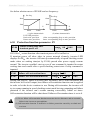
Upon receiving jog run command (for instance, press the
key on keypad)
during waiting state, the inverter run at jog frequency (see function code F2.06~F2.08).
1
closed-loop run
The inverter will come into closed-loop run mode when closed –loop run
control effective parameter is set(F3.00=1). Namely carry on PID adjustment to
specified value and feedback value(proportion integral differential calculation see
F3 group function code) and PID adjustor output is inverter output frequency. Can
make closed-loop run mode ineffective and switch to lower level run mode by
multi-function terminal (function 19).
2
PLC run
The inverter will enter into PLC run mode and run according to run mode
preset(see F4 group function code description) through setting PLC function
effective parameter(F4.00 last bit
0). Can make PLC run mode ineffective and
switch to lower level run mode by multi-function terminal (function 20).
3
multi-section speed run
By nonzero combination of multi-function terminal(1, 2, 3, 4 function)
choose
multisection frequency 1~15(F2.27~F2.41) to run at multisection speed.
4
injection molding run
The inverter will enter into special run for injection molding machine after
injection molding machine function effective parameter is set(F6.00=1).
5
traverse run
The inverter will enter into swing frequency run mode when swing frequency
function effective parameter
F7.00=1
is set. Set relevant swing frequency run
special parameter according to textile swing frequency craft to realize swing
frequency run.
6
common run
Common open loop run mode of general inverter.
In above 6 kinds of run mode except “jog run” the inverter can run according to kinds
of frequency setting method. In “PID run” “PLC run” “multisection run”
run” mode the inverter can also carry on pendular frequency adjustment
34
“common
Shenzhen Gozuk Co., Limted
www.gozuk.com
-----------------------------------------------------------------------------------------------------------------------
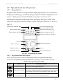
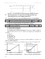
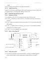
4.2 Operation and use of key board
4.2.1
Keypad layout
Keypad is main unit for receiving command, displaying parameter. It is classified as
LED type and LCD type thereinto LED type keypad is standard configuration. Can
choose to deploy keypad with LCD display according to customer’s need.
Information in English is added by the latter and display data type is noted. Outer
dimension and operation method of these 2 kinds of keypad is identical, as shown in
Fig.4-2.
Failure alarm indicator light
Forward run indicator light
Reverse run indicator light
Displayed current unit A
Mode indicator light
Digital display
Displayed voltage unit
LED
V
Displayed frequency unit Hz
Run key
Digital potentiometer
Stop , reset key
Jog key
Program, exit key
Function, data key
Shift, supervision key
Fig.4-2
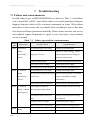
4.2.2
keypad layout sketch
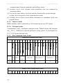
Keypad function description
There are 6 key-presses and one adjusting button for digital potentiometer
on inverter Keypad and function definition of each key is as shown in table 4-1.
Table 4-1 keypad function table
Key
Name
Program/exit key
Shift/supervision key
Function/data key
Function description
Enter into or exit programming state
Can choose modification digit of set data under editor state can
switch display status supervision parameter under other state.
Enter into the next menu or data confirmation
35
Shenzhen Gozuk Co., Limted
www.gozuk.com
----------------------------------------------------------------------------------------------------------------------Jog key
Run key
Stop/reset key
Digital
potentiometer
4.2.3
Jog run is available when pressing this key under keypad mode
Enter into run mode under keypad mode
In common run status the inverter will be stopped according to set
mode after pressing this key if run command channel is set as
keypad stop effective mode. The inverter will be reset and resume
normal stop status after pressing this key when the inverter is in
malfunction status.
Be used to substitute for adding subtracting key and
confirmation key, rotating leftward means subtracting,
rotating rightward means addition, and pressing downward
means confirmation(here function same as
key)
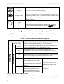
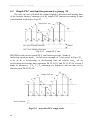
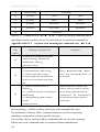
LED and indicator light
4 status indicator light they are MOD mode , ALM alarm , FWD forward
run , REV reverse run from left to right on the LED, their respective indicating
meaning is as shown in table 4-2.
Table 4-2 status indicator light description
item
Function description
Digital display
A, Hz, V
MOD
ALM
FWD
REV
4.2.4
Display current run status parameter and set parameter
unit for relevant current digital displayed physical parameter(for
current is A, for voltage is V for frequency is Hz)
This indicator light is lit in nonsupervision status and
extinguished if no key pressed for a minute, then come back to
supervision status
Alarm indicator light, indicate that the inverter is in over current
or over voltage suppressing status or failure alarm status
currently
Forward run indicator light
indicate that the inverter output
forward phase order and the
connected motor rotate in forward
direction
reverse run indicator light, indicate
that the inverter output reverse
phase order and the connected
motor rotate in reverse direction
The inverter work in DC
brake status if FWD, REV
indicator light is lit at the
same time
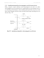
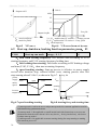
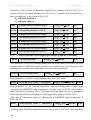
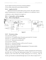
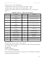
Key board display status
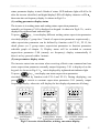
EDS2000 keypad display status is classified as waiting status parameter display,
function code parameter editing status display, malfunction alarm status display, run
36
Shenzhen Gozuk Co., Limted
www.gozuk.com
-----------------------------------------------------------------------------------------------------------------------
status parameter display in total 4 kinds of status. LED indicator light will all be lit
after the inverter electrified, and digital display LED will display character -ENthen enter into set frequency display. As shown in Fig.4-3 a.
(1) waiting parameter display status
The inverter is in waiting status and waiting status supervision parameter
normally set frequency C-00 is displayed on keypad. As shown in Fig.4-3 b unit is
displayed by rightward unit indicator light.
To press
key it can display different waiting status supervision parameter
circularly(display C group fore 7 kinds of supervision parameter acquiescently
other supervision parameter can be defined by function code F2.14
F2.15, for
detail please see C group status supervision parameter in function parameter
schedule graph of chapter 5). Display status will be switched to constant
supervision parameter C-00 (namely set frequency) display automatically if
there’s no key pressed within 1 minute.
(2) run parameter display status
The inverter enters into run status when receiving effective run command and run
status supervision parameter normally output frequency C-01 is displayed on the
keypad. As shown in Fig.4-3 c unit is displayed by rightward unit indicator light.
To press
key
can display run status supervision parameter
circularly (defined by function code F2.14 and F2.15). During displaying, can
press
to switch to constant supervision parameter C-01 (namely output
frequency) display, otherwise will display the last displayed parameter all along.
set frequency
stop
Fig.a
electrification
display-EN -
Fig.b
waiting status display
waiting status parameter
output frequency
common run FWD
Fig.c
run status, display run
status parameter
Fig.4-3 inverter electrification, waiting, run status display
37
Shenzhen Gozuk Co., Limted
www.gozuk.com
-----------------------------------------------------------------------------------------------------------------------
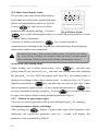
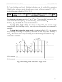
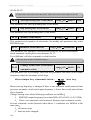
(3) Failure alarm display status
The inverter enters into failure alarm display
status upon detecting failure signal and display
failure code sparklingly(as shown in Fig.4-4);
To press
over current in accelerating
key can look over relative
Can press
Fig.4-4 failure alarm
key to enter into program status to see about Fd group parameter if want
parameter after stopping running
to search failure information.
Can carry on failure restoration by
key, control terminal or
communication command on the keypad after troubleshooting. Keep displaying
failure code if failure exist continuously.
!
For some serious failure such as inverse module protect
etc.
over current, over voltage
must not carry on failure reset forcibly to make the inverter run again without
failure elimination confirmed. Otherwise have danger of damaging the inverter
(4) function code editing status
Under waiting, run or failure alarm status
editing status(If user password is set
the password
press
key
can enter into editing status after inputting
see also FF.00 description and Fig.4-10)
displayed according to three classes menu mode
digital potentiometer or
can enter into
and editing status is
as shown in Fig. 4-5. To press
key can enter into one class by one class. Under
function parameter display status
to press digital potentiometer or
to carry on parameter storage operation To press
key
key can only come back
to upper class menu without stroring modified parameter.(Fig4-5)
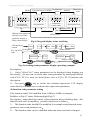
4.2.5
Method for operating keypad
Can carry on various operation to the inverter through keypad
for example
(1) status parameter display switching
After pressing key
display C group status supervision parameter; after
displaying one supervision parameter code for 1 second, will display this
parameter value automatically:(Fig4-6)
38
Shenzhen Gozuk Co., Limted
www.gozuk.com
----------------------------------------------------------------------------------------------------------------------MENU
Set frequency
Switch display
run parameter
MENU /ESC
Waiting status parameter
Display or run status
parameter display or
failure alarm display
Second-class
ENTER
menu
First class menu ENTER
Frequency
setting mode
MENU /ESC
Third-class
menu
Digital provision
MENU/ESC
ENTER/DATAstore para.
Editing status
Fig.4-5 keypad display status switching
1s
LED displayed
50.00
content
Set
frequency
Key operation
C-01
1s
Para. value
Output frequency
C-02
Para. value
Output current
order
1s
1s
parameter
C-14
Pulse input
parameter
C-03
Output voltage
Fig. 4-6 waiting status parameter display operating example
Description
1> Only C-00 C-06 7 status parameters can be displayed when shipping out
the inverter the user can see about other status parameter by modifying function
code F2.14, F2.15 if want, for detail please refer to F2.14, F2.15 function code
description.
2>
Can press
key to switch into constant supervision C-01 display
status directly when the user see about status supervision parameter.
(2) function code parameter setting
Take function code F2.06 modified from 5.00Hz to 6.00Hz as example.
Boldface in Fig.4-7 shows flickering digit.(Fig4-7)
Description under third-class menu, if the parameter has no blinking digit this
function code can’t be modified possible reasons are as follows
1> This function code shouldn’t be modified, for example actual detected status
parameter, run record parameter etc.
2> This function code can’t be modified under run status and can be changed
39
Shenzhen Gozuk Co., Limted
www.gozuk.com
----------------------------------------------------------------------------------------------------------------------LEDdisplayed
content
Key operation
order
50.00
-F0-
-F2-
F2.00
Choose
Enter into
F2 group
editing status
Display first-class function code
menu
Exit editing
status
-F2-
Go back to
First-class
menu
F2.07
F2.06
Function
Choose
group confirmation function code
Go into second-class F2.06
menu
06.00
Store modified
Parameter
value,back to
modification,
second-class menu 5 6
Display next
function code
05.00
05.00
Parameter
modification,
Choose parameter
digit
Function code
confirmation,
Enter into
third-class
menu
Fig.4-7 example for parameter setting and modification
after stopping running
3> Parameter protected. All the function code can’t be modified when function
code F2.16=1 or 2 in order to avoid wrong operation. Need to set the function
code F2.16 to 0 if you want to edit function code parameter.
(3) specified frequency adjustment for common run
Take example modifying specified frequency from 50.00Hz to 40.00Hz at
F0.00=0 during running for explanation.
LED displayed
50.00
content
Key operation
order
Go into specified
frequency modification
status, fast blinking
display of current set
frequency
49.00
Left rotation
one time, set
frequency is
changed based
on step length
45.00
40.00
Stop rotating after set
Adjust
frequency based value reached, after LED
on requirement flash fast for 8 time, set
value effective, go back to
output and display
frequency automatically
Fig. 4-8 set frequency adjustment operation example
Explanation
If the user press any key on the keypad during the process of
specified frequency adjustment, current LED displayed set frequency become
effective and exit from specified frequency adjustment status automatically.
(4) jog run operation
For example, keypad as current run command channel, jog run frequency 5Hz, waiting
status.
40
Shenzhen Gozuk Co., Limted
www.gozuk.com
----------------------------------------------------------------------------------------------------------------------LED displayed
content
5.00
50.00
0.01
press
waiting
keep
Key operation
order
Display run
Display
output frequency
set frequency
50.00
0.01
release
waiting
Output frequency
Output
Fall down to 0Hz
frequency
Increased by 5Hz Stop running
Fig.4-9 jog run operating example
(5) operation for entering to function code editing status after setting user
password
user password FF.00 is set to
6886
. Boldfaced digit in Fig.4-7 shows
blinking bit.
LEDdisplayed
50.00
content
Key operation
order
Nonediting
status
0.0.0.0
0.0.0.6
user password
effective, go into
password
validation status
At first last
Digit flash,
Rotate to 6
-F0Press confirmation
Key, pass validation,
Go into editing status
Fig.4-10
0.0.0.6
6.0.0.6
Rotate
to 6
move cursor
position to
first digit
6.8.8.6
6.8.0.6
6.8.0.6
6.0.0.6
Rotate to
8
Move to
Third
digit
Rotate to
8
Move to
Second
digit
inputting password to go into function code operation
(6) See about failure parameter under failure status
1s
LEDdisplayed
content
E001
Fd.06
1s
50:00
Fd.07
1s
1500
Failure current
1s
Fd.14
Failure run time
Fig.4-11
1111
Fd.13
Failure terminal status
5.5
Fd.08
Failure output freq.
Failure set freq.
Key-press
operation
order
1s
45:00
380
1s
Fd.09
Failure output volt.
failure status searching operation example
Description
1>
If press
key under failure status the user can see about Fd group
41
Shenzhen Gozuk Co., Limted
www.gozuk.com
-----------------------------------------------------------------------------------------------------------------------
function code parameter, search range Fd.06 Fd.14
code number when the user press
LED first display function
key and display parameter digit of this
function code after 1s.
2> When the user see about failure parameter can press
switch back to failure alarm display status (E0XX)
key directly to
(7) keypad key-press locking operation
Under unlocked keypad situation press
key for 5s to lock the keypad.
(8) keypad key-press unlocking operation
Under locked keypad situation press
key for 5s to unlock the keypad.
4.3 Inverter electrification
4.3.1
Check before electrification
Please carry on wiring based on operation requirement provided in “inverter
wiring” of this Service manual.
4.3.2 First electrification
Close input side AC power supply switch after correct wiring and power supply
confirmed, electrify the inverter and keypad LED display “-EN - ”, contactor
closed normally, LED displayed set frequency shows that electrification is
finished. First electrification operation process is shown as figure in next page.
42
Shenzhen Gozuk Co., Limted
www.gozuk.com
----------------------------------------------------------------------------------------------------------------------start
wiring based on 3.5 section
N
wiring correct?
N
input voltage
correct?
Y
Y
electrify
Y
display-ENY
hear
contactor closed
sound?
N
N
Y
display set frequency
Y
N
failure
success
cut off power
check reason
Fig. 4-12
first electrification operation flow
43
Shenzhen Gozuk Co., Limted
www.gozuk.com
-----------------------------------------------------------------------------------------------------------------------
5
5.1
Function parameter schedule graph
Symbol description
---- parameter can’t be changed in process of running
---- parameter can be changed in process of running
---- read-only parameter, unmodifiable
*
5.2
Function parameter schedule graph
F0 –basic run function parameter group
Function
Name
code
F0.00
LCD displayed
Set range
content
Frequency input
Frequency input
0: keypad potentiometer setting
channel selection
channel
1: keypad digit setting
Unit
1
Factory modifidefault cation
0
2: terminal UP/DOWN adjust
setting (stored after power off)
3: serial port setting
4: VCI analog setting (VCI-GND)
5: CCI analog setting (CCI-GND)
6: YCI analog setting (YCI-GND)
7: terminal pulse (PULSE)setting
8: combination setting
(see F2.09 parameter)
9: terminal UP/DOWN adjust
setting (not stored after power
off)
F0.01
Freq. digit setting Freq. digit setting
Lower limit freq. upper limit freq 0.01Hz
F0.02
Run command
Run command
0: keypad run control
channel selection
channel
1: terminal run command control
Run direction
Run direction
0: forward run
setting
setting
1: reverse run
0.00Hz
1
0
1
0
1
0
2: serial port run command control
F0.03
F0.04
Preventing reverse Preventing reverse 0: reverse run allowed
run selection
F0.05
run
Load motor rated rated frequency
1: reverse run banned
1.00
400.00Hz
0.01Hz 50.00Hz
frequency
F0.06
Load motor
rated voltage
1
480V
1V
380V
rated voltage
F0.07
Load motor rated rated power
0.4
999.9KW
0.1
999.9A
0.1KW machine
power
F0.08
confirm
Load motor rated rated current
0.1A
current
F0.09
confim
Load motor rated rated speed
1-9999
1
speed
F0.10
44
Accelerating
machine
1440
(r/min)
accelerating
0
linear accelerating decelerating
1
0
Shenzhen Gozuk Co., Limted
www.gozuk.com
----------------------------------------------------------------------------------------------------------------------decelerating
decelerating
mode
mode selection
mode
1 S curve accelerating decelerating
S curve start
S curve start
10.0
section time
section
decelerating time
mode
F0.11
50.0
accelerating
F0.11+F0.12
0.1(
) 20.0(%)
0.1(
) 60.0(%)
90
F0.12
S curve risetime
S curve rise section 10.0
80.0
accelerating
decelerating time
F0.11+F0.12 90
F0.13
accelerating
accelerating
0
second
decelerating time
decelerating unit
1
minute
1
0
unit
F0.14
Acc time 1
Acc time 1
0.1
6000.0
0.1
20.0
F0.15
Dec time 1
Dec time 1
0.1
6000.0
0.1
20.0
F0.16
Upper limit freq.
Upper limit freq.
Lower limit freq.
F0.17
Lower limit freq.
Lower limit freq.
0.00
F0.18
Lower limit freq. Lower limit freq.
0
run at lower limit freq.
run mode
mode
1
stop running
Torque boost
Torque boost mode 0
F0.19
mode
1
400.00Hz
Upper limit freq.
manual boost
automatic boost
F0.20
Torque boost
Torque boost
0.0
F0.21
V/F curve setting
V/F curve setting
0
constant torque curve
1
degressive torque curve 1
2
degressive torque curve 2
20.0
2.0nd
0.00Hz
1
0
1
0
0.1(%)
2.0(%)
1
0
0.00Hz
the
the
power
degressive torque curve 3
1.2th
4
0.01Hz
power
1.7th
3
0.01Hz 50.00Hz
the
power
custom V/F curve (determined
by F0.22 F0.27 function code)
F0.22
V/Ffreq. value F1 V/Ffreq. valueF1
0.00-F0.24
0.01Hz
F0.23
V/F volt. valueV1 V/Fvolt. valueV1
0.00-F0.25
0.1(%)
0.0(%)
F0.24
V/Ffreq. value F2 V/Ffreq. valueF2
F0.22-F0.26
0.01Hz
0.00Hz
F0.25
V/Fvolt. valueV2
F0.23-F0.27
0.1(%)
0.0(%)
F0.26
V/Ffreq. value F3 V/Ffreq. value F3
F0.24-upper limit frequency
0.01Hz
0.00Hz
F0.27
V/Fvolt. valueV3
F0.25-100.0%(rated voltage)
0.1(%)
0.0(%)
V/Fvolt. valueV2
V/Fvolt. valueV3
F1 –start-up, stop, brake function parameter group
Function
code
F1.00
Name
Start-up run mode
LCD displayed
Set range
content
start-up run
0
start at start-up freq.
mode
1
first brake, then start at
Unit
1
Factory Modifidefault cation
0
start-up freq.
2
speed track start-up
45
Shenzhen Gozuk Co., Limted
www.gozuk.com
----------------------------------------------------------------------------------------------------------------------F1.01
start-up freq.
start-up freq.
0.0
10.00Hz
F1.02
start-up freq. duration
start-up duration
0.0
20.0S
F1.03
F1.04
F1.05
F1.06
F1.07
F1.08
DC brake volt. at start-up start-up brake
0
15
volt.
DC brake time at start-up start-up brake
0.0
20.0S
time
Stop mode
Stop mode
DC brake initiative freq. Stop running
when stop running
0 Dec stop
1
free stop
2
Dec
running
15.00Hz
0.0
20.0s
brake time
DC brake voltage when Stop running
stop running
0
0.00Hz
0.1s
0.0s
1
0
0.1s
0.0s
1
0
0.01Hz
0.00Hz
0.0s
0.0s
1
0
DC brake stop
0.0
brake freq.
DC brake time when stop Stop running
0.01Hz
15
brake voltage
F2 –auxiliary run function parameter group
Function
F2.00
F2.01
F2.02
F2.03
LCD displayed
Name
code
Analog
filter
Set range
content
time filter time
0.00
30.00s
constant
Forward reverse run
Forward reverse run
dead-section time
dead-section
0.0 3600.0s
Automatic energy
Automatic energy
0 no action
save run
save run
1
AVR function
AVR function
action
0 no action
1
Unit
Factory Modifidefault cation
0.01s
0.20s
0.1s
0.0s
1
0
1
0
1
0
action all the time
2 no action only during Dec
F2.04
F2.05
Slip frequency
Slip compensation
compensation
Carrier wave freq.
0 150(
)0-no slip
frequency compensation
Carrier wave freq.
0.7
16.0K
depend
0.1K
on
machine
type
F2.06
Jog run frequency
Jog run frequency
0.10
F2.07
Jog Acc time
Jog Acc time
0.1
F2.08
Jog Dec time
Jog Dec time
0.1
F2.09
Frequency input
Frequency
0 VCI
CCI
channel combination
combination setting
1 VCI
CCI
2 YCI
CCI
3 YCI
CCI
4 VCI
YCI
5 VCI
YCI
6
46
50.00Hz
0.01Hz
5.00Hz
60.0s
0.1s
20.0s
60.0s
0.1s
20.0s
1
0
exterior pulse provision
Shenzhen Gozuk Co., Limted
www.gozuk.com
----------------------------------------------------------------------------------------------------------------------CCI
7
exterior pulse provision
CCI
8 MAX
9 MIN
10
VCI
VCI
MAX
YCI
YCI
YCI
VCI
PULSE
11 MIN
YCI
VCI
PULSE
12
VCI
YCI any nonzero
value effective
VCI
preferred
13
VCI
CCI any nonzero
value effective
VCI
preferred
14
VCI+YCI(for
controlling simple strain)
15
RS485+CCI
16
RS485-CCI
17
RS485+VCI
18
RS485-VCI
19
RS485+keypad
20
RS485- keypad
21
VCI+ keypad
22
VCI- keypad
23
CCI+ keypad
24
CCI- keypad
25
reserved
26
reserved
potentiometer
potentiometer
potentiometer
potentiometer
potentiometer
potentiometer
27 reserved
F2.10
Principal subordinate
Principal subordinate 0
machine
machine
communication
communication
frequency provision
frequency provision
500
1(%)
100(%)
1(%)
100(%)
1(%)
100(%)
proportion
F2.11
F2.12
Output voltage
Output voltage
emendation factor
emendation factor
Heat sink temperature
Heat sink
emendation factor
temperature
50
150
50
150
emendation factor
47
Shenzhen Gozuk Co., Limted
www.gozuk.com
----------------------------------------------------------------------------------------------------------------------F2.13
F2.14
Load motor speed
Load motor speed
emendation factor
emendation factor
LED display control 1
Control 1
50
150
0000-1111
1(%)
100(%)
1
0000
1
0000
1
0
first bit running time
0 not display
1
display
second bit
accumulative
time
0 not display
1
display
third bit input terminal
0
not display
1
display
kilobit(fourth bit)
output
terminal
0 not display
1
F2.15
F2.16
LED display control 2
Parameter operation
control
48
display
0000-1111
first bit analog input VCI
0 not display
1 display
second bit
analog input
YCI
0 not display
1 display
third bit analog input CCI
0 not display
1 display
kilobit(fourth bit) exterior
pulse input
0 not display
1 display
Parameter operation 0 all parameter allowed to
be modified
1 except this parameter all
other parameter not allowed
to be
modified
2 except F0.01 and this
parameter all other
parameter not allowed to be
modified
3 clear history failure record
4 renew factory default
5 parameter uploading
6 parameter downloading
Control 2
Shenzhen Gozuk Co., Limted
www.gozuk.com
----------------------------------------------------------------------------------------------------------------------F2.17
Communication
Communication
LED first bit baud rate
configuration
configuration
option
1
0005
1
1
0.1s
0.0s
0 300BPS
1
600BPS
2
1200BPS
3
2400BPS
4
4800BPS
5
9600BPS
6
19200BPS
7
38400BPS
LED second bit data format
0
1
8
1format
no
1 format
even
1 format
odd
checkout
1
1
8
checkout
2 1
8
checkout
F2.18
Local address
Local address
0
127
127 is broadcast
address
Communication
Communication
overtime
overtime
Local responsion
Local responsion
delay
delay
1ms
5ms
F2.21
Acc time 2
Acc time 2
0.1
6000.0
0.1
20.0
F2.22
Dec time 2
Dec time 2
0.1
6000.0
0.1
20.0
F2.23
Acc time 3
Acc time 3
0.1
6000.0
0.1
20.0
F2.24
Dec time 3
Dec time 3
0.1
6000.0
0.1
20.0
F2.25
Acc time 4
Acc time 4
0.1
6000.0
0.1
20.0
F2.26
Dec time 4
Dec time 4
0.1
6000.0
0.1
20.0
Multisection freq. 1
Multisection freq. 1
Lower limit freq.
0.01Hz
5.00Hz
Multisection freq. 2
Multisection freq. 2
Lower limit freq.
F2.19
F2.20
F2.27
F2.28
F2.29
F2.30
F2.31
F2.32
F2.33
F2.34
0.0 1000.0s
0 1000ms
upper
limit freq.
upper
limit freq.
Multisection freq. 3
Multisection freq. 3
Lower limit freq.
upper
limit freq.
Multisection freq. 4
Multisection freq. 4
Lower limit freq.
upper
limit freq.
Multisection freq. 5
Multisection freq. 5
Lower limit freq.
upper
limit freq.
Multisection freq. 6
Multisection freq. 6
Lower limit freq.
upper
limit freq.
Multisection freq. 7
Multisection freq. 7
Lower limit freq.
upper
limit freq.
Multisection freq. 8
Multisection freq. 8
Lower limit freq.
limit freq.
upper
0.01Hz 10.00Hz
0.01Hz 20.00Hz
0.01Hz 30.00Hz
0.01Hz 40.00Hz
0.01Hz 45.00Hz
0.01Hz 50.00Hz
0.01Hz
5.00Hz
49
Shenzhen Gozuk Co., Limted
www.gozuk.com
----------------------------------------------------------------------------------------------------------------------F2.35
F2.36
F2.37
F2.38
F2.39
F2.40
F2.41
Multisection freq. 9
multisection freq. 9
Lower limit freq.
upper
limit freq.
Multisection freq. 10
Multisection freq. 10 Lower limit freq.
upper
limit freq.
Multisection freq. 11
Multisection freq. 11 Lower limit freq.
upper
limit freq.
Multisection freq. 12
Multisection freq. 12 Lower limit freq.
upper
limit freq.
Multisection freq. 13
Multisection freq. 13 Lower limit freq.
upper
limit freq.
Multisection freq. 14
Multisection freq. 14 Lower limit freq.
upper
limit freq.
Multisection freq. 15
Multisection freq. 15 Lower limit freq.
upper
limit freq.
0.01Hz 10.00Hz
0.01Hz 20.00Hz
0.01Hz 30.00Hz
0.01Hz 40.00Hz
0.01Hz 45.00Hz
0.01Hz 50.00Hz
0.01Hz 50.00Hz
F2.42
Jumping freq. 1
Jumping freq. 1
0.00
400.00Hz
0.01Hz
0.00Hz
F2.43
Jumping freq. 1 range
Jumping range 1
0.00
30.00Hz
0.01Hz
0.00Hz
F2.44
Jumping freq. 2
Jumping freq. 2
0.00
400.00Hz
0.01Hz
0.00Hz
F2.45
Jumping freq. 2 range
Jumping range 2
0.00
30.00Hz
0.01Hz
0.00Hz
F2.46
Jumping freq. 3
Jumping freq. 3
0.00
400.00Hz
0.01Hz
0.00Hz
F2.47
Jumping freq. 3 range
Jumping range 3
0.00
30.00Hz
0.01Hz
0.00Hz
F2.48
Setting run time
Setting run time
0 65535 hours
1
0
Accumulative run
Accumulative run
0 65535 hours
time
time
1
0
F2.49
*
F3 –closed-loop run function parameter group
Function
code
F3.00
Name
Set range
content
Unit
Factory Modifdefault ication
Closed-loop function 0 closed-loop control
ineffective
selection
1 PID closed-loop control
effective
2 reserved
1
0
Provision channel
Provision channel
0
digital voltage provision
1
1
selection
selection
1
digital pressure provision
2
VCI analog 0 10V voltage
1
1
Closed-loop run
control selection
F3.01
LCD displayed
provision
F3.02
Feedback
selection
50
channel Feedback
selection
3
CCI analog provision
4
keypad potentiometer
provision
channel 0 VCI analog input voltage 0
10V
1 CCI analog input
2 VCI+CCI
3 VCI-CCI
4 Min { VCI, CCI }
5 Max { VCI, CCI }
Shenzhen Gozuk Co., Limted
www.gozuk.com
----------------------------------------------------------------------------------------------------------------------F3.03
Digital voltage setting
F3.04
Digital pressure setting Digital pressure setting
F3.05
Minimum specified Minimum specified 0.0 maximum specified value;
F3.06
Digital voltage setting
value
value
feedback value
Feedback of minimum
responding to
specified value
minimum specified
0.00 10.00V
0.01
0.00V
0.000 9.999Mpa
0.01
0.000Mpa
0.1(%)
0.0(%)
0.1(%)
0.0(%)
percentage relative to 10.00V
0.0
100.0(%)
value
F3.07
F3.08
F3.09
F3.10
pressure value
pressure value responding
responding to F3.06
to minimum provision
maximum specified maximum specified
value
feedback value
responding to
maximum specified
value
pressure value
responding to F3.09
0.000 9.999Mpa
Minimum specified value
value
100.0
0.001 0.000Mpa
0.1(%) 100.0(%)
Feedback of maximum
specified value
100.0
0.0
pressure value responding
0.000 9.999Mpa
to minimum provision
0.1(%) 100.0(%)
0.001 1.000Mpa
F3.11
proportion gain KP proportion gain
0.000
9.999
0.001
0.050
F3.12
Integral gain KI
Integral gain
0.000
9.999
0.001
0.050
F3.13
Differential gain
Differential gain
0.000
9.999
0.001
0.000
F3.14
Sampling time T
Sampling time
0.01 1.00s
F3.15
Deviation margin
Deviation margin
0.1(%)
0.0 20.0
remark percentage relative to
closed-loop specified maximum
value
Closed-lop preset
Closed-lop preset
frequency
frequency
F3.16
F3.17
Closed-loop preset
frequency
holding
time
Closed-loop preset
0
upper limit frequency
0.0-6000s
0.01s
0.10s
2.0(%)
0.01Hz 0.00Hz
0.1s
0.0s
frequency holding
time
F3.18
Revival frequency
Threshold
0.00
400.00Hz
0.01Hz 0.00Hz
F3.19
Sleep frequency
Integral separation
PID adjusting
threshold
Closed-loop
adjusting
characteristic
Back difference
0.00
400.00Hz
0.01Hz 0.00Hz
F3.20
F3.21
F3.22
reserved
F3.23
reserved
F3.24
reserved
F3.25
0.0
100.0%
0: positive
1: negative
failure relay delay
Range:
time
1:delay 5s
0.1%
100.0
1
0
0:no delay time
51
Shenzhen Gozuk Co., Limted
www.gozuk.com
----------------------------------------------------------------------------------------------------------------------F4 –simple PLC function parameter group
Function
code
F4.00
Name
Simple PLC
LCD displayed
Set range
content
PLC run setting
running setting
LED first bit
0
no action
1
stop after single circulation
2
keep final value after single
Unit
Factory Modifdefault ication
1
000
1
000
0.1
10.0
circulation
3
consecutive circulation
LED second bit
0
start again from first section
1
continue to run at mid-section
frequency
LED third bit PLC run time unit
F4.01
Section 1 setting
Section 1 setting
0
second
1
minute
000 322
LED first bit frequency setting
0
multisection freq. i (i=1~7)
1
freq. determined by F0.00
function code
2
multisection closed-loop
provision i (i=1~7)
LED second bit
run direction
selection
0
forward run
1
reverse run
2
determined by run command
LED third bit Acc/Dec time
selection
0
Acc/Dec time 1
1
Acc/Dec time 2
2
Acc/Dec time 3
3
Acc/Dec time 4
6000.0
F4.02
Section 1 run time
Section 1 time
0
F4.03
Section 2 setting
Section 2 setting
000
F4.04
Section 2 run time
Section 2 time
0
F4.05
Section 3 setting
Section 3 setting
000
F4.06
Section 3 run time
Section 3 time
0
F4.07
Section 4 setting
Section 4 setting
000
F4.08
Section 4 run time
Section 4 time
0
F4.09
Section 5 setting
Section 5 setting
000
F4.10
Section 5 run time
Section 5 time
0
F4.11
Section 6 setting
Section 6 setting
000
52
322
6000.0
322
6000.0
322
6000.0
322
6000.0
322
1
000
0.1
10.0
1
000
0.1
10.0
1
000
0.1
10.0
1
000
0.1
10.0
1
000
Shenzhen Gozuk Co., Limted
www.gozuk.com
----------------------------------------------------------------------------------------------------------------------F4.12
Section 6 run time
Section 6 time
0
F4.13
Section 7 setting
Section 7 setting
000
F4.14
Section 7 run time
Section 7 time
0
6000.0
0.1
322
6000.0
10.0
1
000
0.1
10.0
F5 –terminal correlative function parameter group
Function
code
F5.00
Name
LCD displayed
content
Set range
Unit
1
Input terminal X1
X1 terminal
0
leave control terminal unused
function selection
function
1
multisection speed control
Factory Modifdefault ication
0
terminal 1
2
multisection speed control
terminal 2
3
multisection speed control
terminal 3
4
multisection speed control
terminal 4
5
external forward run jog control
6
external reverse run jog control
7
Acc/Dec time option terminal 1
8
Acc/Dec time option terminal 2
9
external device failure input
10
external reset input
11
free shutdown input
12
external stop-running order
13
shutdown DC braking input
command DB
14
inverter run banned
15
frequency increasing control
(UP)
16
frequency degression control
(DOWN)
17
Acc/Dec ban command
18
three-line run control
19
closed-loop ineffective
20
PLC ineffective
21
simple PLC pause control
22 PLC stop status reset
23
frequency provision channel
option 1
24
frequency provision channel
option 2
25
frequency provision channel
option 3
26
frequency switched to CCI
27
command switched to terminal
53
Shenzhen Gozuk Co., Limted
www.gozuk.com
----------------------------------------------------------------------------------------------------------------------28
run command channel option 1
29
run command channel option 2
30
reserved
31
reserved
32
reserved
33
swing frequency jump-in
34
reserved
35
external interruption input
36
interior counter reset end
37
interior counter triggering end
38
pulse frequency input
only
effective for X7,X8
F5.01
F5.02
F5.03
F5.04
F5.05
F5.06
F5.07
F5.08
F5.09
Input terminal X2
X2 terminal
function selection
function
Input terminal X3 X3 terminal
function selection
function
Input terminal X4
X4 terminal
function selection
function
Input terminal X5
X5 terminal
function selection
function
Input terminal X6
X6 terminal
function selection
function
Input terminal X7
X7 terminal
function selection
function
Input terminal X8
X8 terminal
function selection
function
39
reserved
40
reserved
41
reserved
Same as above
Same as above
Same as above
Same as above
Same as above
Same as above
Same as above
FWD/REV run mode run mode selection 0
double-line control mode 1
selection
1
double-line control mode 2
2
three-line control mode 1
3
three-line control mode 2
UP/DOWN
UP/DOWN velocity 0.01 99.99Hz/s
1
0
0.01Hz/s 1.00Hz/s
velocity
F5.10
Open circuit
Y1function
0
collector
option
1 frequency arriving signal FAR
output terminal Y1
inverter running
RUN
2
frequency level detect signal
3
frequency level detect signal
4
overload warning alarm signal
5
output frequency reach high
6
output frequency reach low
output setting
(FDT1)
(FDT2)
(OL)
limit FHL
54
1
0
Shenzhen Gozuk Co., Limted
www.gozuk.com
----------------------------------------------------------------------------------------------------------------------limit FLL
7 inverter lacking voltage blockage
shutdown (LU)
8 external failure stop-runnin
EXT
9 inverter zero rotate speed running
10
PLC running
11
simple PLC section running
12
PLC finish a cycle running
13
reserved
14
inverter ready to run (RDY)
15
inverter failure
16
swing frequency high and
17
interior counter reach final
18
interior counter reach specified
19
set run time arriving
finished
low limit restriction
value
value
F5.11
Open circuit
Y2 function
collector output
option
Same as above
1
0
terminal Y2 output
setting
F5.12
Frequency arriving
equivalent
(FAR) checkout
frequency range
0.00
50.00Hz
0.01Hz 5.00Hz
0.00
high limit frequency
0.01Hz 10.00Hz
scope
F5.13
FDT1 (frequency
FDT1 electric
level) electric level level
F5.14
FDT1 lag
FDT1 lag
0.00 50.00Hz
0.01Hz 1.00Hz
F5.15
FDT2 (frequency
FDT2 electric
0.00
0.01Hz 10.00Hz
high limit frequency
level) electric level level
F5.16
FDT2 lag
F5.17
Analog output (AO1) AO1 output
FDT2 lag
0 output frequency(0
0.00 50.00Hz
selection
frequency)
1 output current(0
0.01Hz 1.00Hz
high limit
1
0
1
0
0.01
1.00
2×rated
current)
2 output voltage(0
1.2×load
motor rated voltage)
F5.18
Analog output (AO2) AO2 output
3
bus-bar voltage(0
4
PID provision (0.00-10.00V)
5
PID feedback (0.00-10.00V)
Same as above
800V)
selection
F5.19
Analog output
AO1gain
0.50
2.00
(AO1) gain
55
Shenzhen Gozuk Co., Limted
www.gozuk.com
----------------------------------------------------------------------------------------------------------------------F5.20
F5.21
F5.22
reserved
Analog output
AO2 gain
0.50
Digital output
Same as F5.17
2.00
0.01
1.00
1
0
0.1KHz
10.0
0--9999
1
0
0--9999
1
0
(AO2) gain
DO terminal output
function selection
F5.23
DO maximum pulse maximum pulse
0.1
output frequency
maximum pulse output frequency
output
50.0(max. 50KHz) DO
corresponds to max. value choosed
by F5.22
F5.24
F5.25
Set interior counting
Set counting
value reach provision
value
Specified interior
Specified
counting value reach
counting value
provision
F6 group 1—special function parameter group for injection molding machine (EDS2800)
Function
F6.00
Min.
Factory
Modific
unit
default
-ation
1
0
1
2
0.01~1.00
0.01
0.50
0.01~1.00
0.01
0.50
Name
code
Description
Special parameter selection 0 special parameter for injection
for injection molding
molding machine ineffective
machine
1
special parameter for injection
combination selection
0
set 1I
1
set 2I
2
1I
weighting factor
2I
weighting factor
molding machine effective
F6.01
3 VI1+1I
F6.02
External input 1I
4
VI1+1I+2I
5
MAX{1I
6
MIN{1I
2I }
2I }
weighting factor
F6.03
External input 2I
weighting factor
F6.04
1I Min. input quantity
0.01~1.00
0.01
0.20
F6.05
Frequency corresponding
0.00~400.00
0.01
10.00
0.01
1.00
0.01Hz
50.00Hz
0.01
0.20
to 1I Min. input
quantity
F6.06
1I Max. input quantity
0.01~1.00
F6.07
Frequency corresponding
0.00~400.00
to 1I Max. input
quantity
F6.08
56
2I Min. input quantity
0.01~1.00
Shenzhen Gozuk Co., Limted
www.gozuk.com
----------------------------------------------------------------------------------------------------------------------F6.09
Frequency corresponding
0.00~400.00
0.01Hz
10.00Hz
0.01
1.00
0.01Hz
50.00Hz
1
0
0.01
0.00
0.0 F6.07
0.01Hz
0.00Hz
0.0 F6.06
0.01
0.00
0.0 F6.07
0.01Hz
0.00Hz
0.0 F6.10
0.01
0.0
0.0 F6.11
0.01Hz
0.00Hz
0.0 F6.10
0.01
0.00
0.0 F6.11
0.01Hz
0.00Hz
to 2I Min. input
quantity
F6.10
2I Max. input quantity
0.01~1.00
F6.11
Frequency corresponding
0.00~400.00
to 2I Max. input
quantity
F6.12
Inflexion setting
0 inflexion ineffective
1
F6.13
1I middle inflexion
inflexion effective
F6.04 F6.06
current/voltage 1
F6.14
Frequency corresponding
to F6.13
F6.15
1I middle inflexion
current/voltage 2
F6.16
Frequency corresponding
to F6.15
F6.17
2I middle inflexion
current/voltage 1
F6.18
Frequency corresponding
to F6.17
F6.19
2I middle inflexion
current/voltage 2
F6.20
Frequency corresponding
to F6.19
F6 group 2—constant pressure water supply parameter group (EDS2000)
Function
code
Name
Description
0.0-6000.0s
Min.
Factory
Modific
unit
default
-ation
0.1
0.0
F6.00
Sleep delay time
F6.01
Revival delay time
0.0-6000.0s
0.1
0.0
F6.02
Start-up frequency of first
0.00-400.0Hz
0.01
0.00
0.00-400.0Hz
0.01
0.00
0.00-400.0Hz
0.01
0.00
0.00-400.0Hz
0.01
0.00
0.00-400.0Hz
0.01
0.00
0.00-400.0Hz
0.01
0.00
0.0-6000.0s
0.01
0.00
sub-machine
F6.03
Start-up frequency of second
sub-machine
F6.04
Start-up frequency of third
sub-machine
F6.05
Stop frequency of first
sub-machine
F6.06
Stop frequency of second
sub-machine
F6.07
Stop frequency of third
sub-machine
F6.08
Start-up delay of
57
Shenzhen Gozuk Co., Limted
www.gozuk.com
----------------------------------------------------------------------------------------------------------------------sub-machine
F6.09
stop delay of sub-machine
0.0-6000.0s
F6.10
Quantity of sub-machine
0-3
1
0
F6.11
Automatic switching interval
0000-9999 minutes
1
0000
Real value of link
0.0-100.0%
0.1
0.0
0.000-9.999s
1
0000
0000-9999
1
0000
F6.12
0.01
0.00
sub-machine automatic
switching
F6.13
Starting delay of speed
regulating motor
F6.14
Water supply special relay
*
status display
F6.15
reserved
F6.16
reserved
F6.17
reserved
F6.18
reserved
F6.19
reserved
F6.20
reserved
F7 –swing frequency special function parameter group
Function
code
F7.00
F7.01
F7.02
F7.03
F7.04
F7.05
F7.06
F7.07
58
Name
LCD displayed
content
traverse function traverse function
selection
selection
Setting range
Min.
Factory Modific
unit
1
default
0
0 traverse function not used
1 Swing frequency function
used
LED first bit jump-in mode
1
0 automatic jump -in mode
1 terminal manual jump-in mode
LED second bit
0 changing traverse amplitude
1 fixed traverse amplitude
notice traverse center
frequency input channel set by
F0.00 function parameter
0.0 50.0 %
0.1(%)
traverse run
mode
Traverse run mode
traverse
amplitude
Sudden jumping
frequency
traverse cycle
traverse amplitude
Sudden jumping
frequency
traverse cycle
0.0 50.0
Triangle wave
risetime
traverse preset
frequency
traverse preset
frequency
latency time
risetime
0.0 98
traverse preset
frequency
Traverse latency
time
0.00 400.00Hz
%
0.1(%)
0.1 999.9s
%
0.0 6000s
traverse cycle
00
0.0(%)
0.0(%)
0.1s
10.0s
0.1(%)
50.0(%)
0.01Hz
0.00Hz
0.1s
0.0s
-ation
Shenzhen Gozuk Co., Limted
www.gozuk.com
----------------------------------------------------------------------------------------------------------------------F8 –frequency provision function parameter group
Function
code
F8.00
F8.01
F8.02
F8.03
F8.04
F8.05
F8.06
LCD displayed
Name
content
VCI min. provision
VCI min.
Setting range
Min.unit
Factory Modificdefault
0.00 F8.02
0.01V
0.00V
VCI small freq.
0.00 high limit frequency
0.01Hz
0.00Hz
VCI max.
0.00 10.00V
0.01V
10.00V
VCI big freq.
0.00 high limit frequency
0.01 Hz
50.00Hz
CCI min.
0.00 F8.06
0.01V
0.00V
CCI small freq.
0.00 high limit frequency
0.01 Hz
0.00Hz
CCI max.
0.00 10.00V
0.01V
10.00V
CCI big freq.
0.00 high limit frequency
0.01 Hz
50.00Hz
YCI min.
0.00 F8.10
0.01V
0.00V
YCI small freq.
0.00 high limit frequency
0.01 Hz
0.00 Hz
YCI max.
0.00 10.00V
0.01V
10.00V
0.00 high limit frequency
0.01 Hz
50.00Hz
0.1K
10.0K
0.1K
0.0K
0.01 Hz
0.00 Hz
0.1K
10.0K
0.01 Hz
50.00 Hz
ation
provision
VCI min. provision
corresponding freq.
VCI max. provision
provision
VCI max. provision
corresponding freq.
CCI min. provision
provision
CCI min. provision
corresponding freq.
CCI max. provision
provision
F8.07
F8.08
F8.09
CCI max. provision
corresponding freq.
YCI min. provision
provision
YCI min. provision
corresponding freq.
F8.10
YCI max. provision
provision
F8.11
YCI max. provision
YCI big freq.
corresponding freq.
F8.12
PULSE max. input pulse
F8.13
PULSE min. provision PULSE min.
PULSE max. pulse 0.1 50.0K
provision
F8.14
PULSE min. provision PULSE small
corresponding freq.
F8.15
provision)
0.00 high limit frequency
freq.
PULSE max. provision PULSE max.
provision
F8.16
0.0 F8.12(PULSE max.
PULSE max. provision PULSE big freq.
F8.13 (PULSE min. provision)
F8.12 (max. output pulse)
0.00 high limit frequency
corresponding freq.
F9 –protection correlative function parameter group
Function
code
F9.00
Name
LCD displayed
content
Setting range
Instantaneous power off
Power off restarting 0.0 10.0S
restarting latency time
time 0
Min.unit
0.1S
Factory Modificdefault
ation
0.0S
0 indicates ineffective power
off restarting
59
Shenzhen Gozuk Co., Limted
www.gozuk.com
----------------------------------------------------------------------------------------------------------------------F9.01
Failure self-renew times Failure
0
10
1
0
0.1S
5.0S
1
1
0.1(%)
100.0(%)
1(%)
130(%)
0.1s
5.0s
1
1
1(%)
140(%)
1(%)
150(%)
self-renew times 0 shows no automatic reset
function
remark: no automatic reset
function for overload and
overheat
F9.02
F9.03
F9.04
Failure self-renew interval Failure
Motor overload protection overload protection 0
no action
Mode selection
inverter close off output
F9.06
F9.07
F9.08
selection
Motor overload protection Electronic
coefficient
F9.05
0.5 20.0S
self-renew time
20.0-120.0
%
thermal relay
Overload warning alarm Overload
checkout level
1
20 200
%
checkout level
Overload warning alarm Overload
0.0 20.0s
Delay time
checkout time
Overvoltage stall
Overvoltage stall 0
ban
selection
selection
allow
Overvoltage stall
Overvoltage stall 120-150
point
point
Automatic current
Automatic
F9.09
limit level
current limit
F9.10
Frequency declining
Frequency
rate during current
declining rate
1
110 200
%
%
level
0.00 99.99Hz/s
0.01Hz/s 10.00Hz/s
limiting
F9.11
Automatic current
Automatic
0 automatic current limiting is
limiting action
current
ineffective during constant
selection
limiting action
speed
1
0
1
000
1
00
1 automatic current limiting is
effective during constant
F9.12
F9.13
60
speed
remark always effective during
Acc/Dec
LED first bit communication
Abnormal action
0 alarm and stop running free
1 not alarm and continue to run
LED second bit (reserved)
LED third bit E2PROM abnormal action option
0 alarm and stop running free
1 not alarm and continue to run
protection action
Protection
selection 1
selection 1
protection action
protection
LED first bit lacking voltage
selection 2
selection 2
Failure instruction action selection
0
no action
1
action
regard voltage lack
Shenzhen Gozuk Co., Limted
www.gozuk.com
----------------------------------------------------------------------------------------------------------------------as failure
LED second bit
G/P type
machine
0 G type machine
1 P type machine
Fd –failure record function parameter group
Function
Fd.00
Fd.01
Fd.02
Fd.03
Fd.04
Fd.05
Fd.06
Fd.07
Fd.08
Fd.09
Fd.10
Fd.11
Fd.12
Fd.13
Fd.14
LCD displayed
Name
code
Setting range
content
Min.unit
Previous one time failure Previous one time Previous one time failure
record
failure
three
*
1
0
*
1
0
*
1
0
*
1
0
*
1
0
*
Set freq. of previous failure
0.01Hz
0
*
0.01Hz
0
*
0.1A
0
*
1V
0
*
1V
0
*
1(r/m)
0
*
0
*
0
*
0
*
record
time Previous three time Previous three time failure
failure record
failure
record
Previous four time failure Previous four time Previous four time failure
record
failure
record
Previous five time failure Previous five time Previous five time failure
record
failure
record
Previous six time failure Previous six time Previous six time failure
record
Set
failure
freq.
of
c-ation
0
record
failure
Previous
Modifi
default
1
Previous two time failure Previous two time Previous two time failure
record
Factory
record
previous failure set freq.
failure
output freq. of previous
Failure output
output freq. of previous
failure
failure
failure
output current of previous Failure current
output current of previous
failure
failure
output voltage of previous Failure
failure
voltage
DC bus-bar voltage of
Failure
Previous failure
voltage
Load motor speed of
Failure
Previous failure
speed
Module
temperature
output output voltage of previous
failure
bus-bar DC bus-bar voltage of
Previous failure
motor Load motor speed of
Previous failure
of Failure module
Module temperature of
1
previousfailure
temperature
Previous failure
Input terminal status of
Failure
terminal Input terminal status of
previous failure
status
previous failure
Accumulative run time of Failure run time
Accumulative run time of
previous failure
previous failure
FF –password and manufacturer function parameter group
Function
code
Name
LCD displayed
content
Setting range
Min.unit
Factory
Modif-ic
default
ation
61
Shenzhen Gozuk Co., Limted
www.gozuk.com
----------------------------------------------------------------------------------------------------------------------FF.00
FF.01
User password
User password
0000 9999
Manufacturer
Manufacturer
0000 9999
password
password
FF.02-
Manufacturer’s
FF.0X
special parameter
1
0000
1
0000
C –supervision function parameter group
Function
Name
code
C-00
Set frequency
C-01
Output freq.
Output current
LCD displayed
Description
content
Set frequency
Min.unit
Factory
Modif-
default
ication
Current set frequency
0.01HZ
Output freq.
Current output freq.
0.01HZ
*
Output current
Virtual value of current
0.1A
*
1V
*
1V
*
r/m
*
1
*
1h
*
1h
*
C-02
output
current
Output voltage Output voltage
C-03
Virtual value of current
output
voltage
C-04
C-05
DC bus-bar
bus-bar voltage
Current DC bus-bar voltage
Load motor speed
Product of output frequency
voltage
Load motor
speed
1
and
load motor speed emendation
factor
C-06
C-07
C-08
C-09
C-10
C-11
C-12
C-13
C-14
62
Module
Module
IGBT
temperature
temperature
temperature
heat
Run time
Run time
sink
Inverter electrification run
time
accumulative
accumulative time
Inverter accumulative run
run time
time
Input terminal Input terminal
Switch
status
terminal status
output
output terminal
terminal status
Analog input
Switch
value
value
input
*
output
*
terminal status
Analog input VCI
Analog input value of VCI
V
*
Analog input YCI
Analog input value of YCI
V
*
Analog input CCI
Analog input value of CCI
V
*
Exterior pulse input
Exterior pulse input
VCI
Analog input
YCI
Analog input
CCI
Exterior pulse
input
*
Shenzhen Gozuk Co., Limted
www.gozuk.com
-----------------------------------------------------------------------------------------------------------------------
Factory default supervision parameter C-07~C-14 is hidden please modify
note
corresponding value of F2.14 F2.15 if need to supervise these parameters.
(1) Input terminal status corresponding relation is as follows
shows terminal input ineffective
shows terminal input effective
X1terminal status
X2 terminal status
X3 terminal status
X4 terminal status
REV input terminal
FWD input terminal
X6 terminal status
X5 terminal status
(2) Output terminal status corresponding relation is as follows
Y1 output terminal
Y2 output terminal
63
Shenzhen Gozuk Co., Limted
www.gozuk.com
-----------------------------------------------------------------------------------------------------------------------
6
Detailed function description
Listed column content for parameter function code description in this chapter is as
follows
code
6.1
name
Basic run function parameter group
F0.00
Frequency input channel selection
Set range or
Factory
description
default
F0
range 0~9
0
0 keypad digital potentiometer. Set running frequency by keypad digital
potentiometer, reserve set frequency after power off.
1 keypad frequency number setting. Initial set frequency value is F0.01
can change set frequency by changing F0.01 parameter through keypad.
2 terminal UP/DOWN adjust set frequency(stored after power off).
Initial set frequency value is F0.01 and adjust set running frequency by
terminal UP/DOWN.
3 serial port provision. Serial port frequency set initial value is F0.01
change set frequency by setting F0.01 through serial port.
4 VCI analog setting(VCI GND).Frequency setting determined by VCI
terminal analog voltage input voltage range DC0~10V.
5 CCI analog setting (CCI GND). Frequency setting determined by CCI
terminal analog voltage /current input range DC0~10V (CCI jumping wire
choose V side) DC 4~20mA (CCI jumping wire choose A side).
6 YCI analog setting (YCI GND). Frequency setting determined by YCI
terminal analog voltage input range DC0~10V (YCI jumping wire choose10V
side or DC0~5V(YCI jumping wire choose 5V side).
7 terminal pulse (PULSE) setting. Frequency set by terminal pulse only
input through X7 or X8 see F5.06~F5.07 definition
input pulse signal spec
voltage range15~30V frequency range 0~50.0KHz.
8 combination setting. See function parameter F2.09 set frequency by each
channel combination setting.
9 terminal UP/DOWN adjust set frequency not stored after power off
Initial set frequency value is F0.01 and adjust set running frequency by
terminal UP/DOWN.
Relation between frequency and input information is determined by function code
note
64
F8.00~F8.16 when frequency input channel is 4, 5, 6, 7
please see Section 6.9.
Shenzhen Gozuk Co., Limted
www.gozuk.com
-----------------------------------------------------------------------------------------------------------------------
F0.01
Freq. number setting
range
low limit
high limit
0.00Hz
F0.01 parameter is original set frequency of the inverter when frequency setting
channel is defined as number setting (F0.00
F0.02
1, 2 3).
range
Run command channel selection
0, 1, 2
0
0
keypad run frequency command channel. Start and stop the inverter
1
terminal run command channel. Start and stop the inverter by exterior
by
,
,
key on the keypad.
control terminal FWD, REV, X1~X8 etc..
serial port run command channel. Start and stop the inverter by RS485
2
or interface.
The inverter can change run command channel by modifying F0.02 during waiting and
!
running please confirm that modification is allowed during running on the spot.
F0.03
Range
Run direction setting
0, 1
0
This function is only effective for keypad and serial port run command channel
ineffective for terminal run command channel.
1 inverter reverse run
0 inverter forward run
F0.04
range
Preventing reverse run selection
0, 1
0
0
inverter reverse run allowed
1
inverter reverse run banned. The inverter will stop outputting if reverse
run command available.
If this function is set to 1
note
effective for keypad run command channel, terminal
run command channel and serial port run command channel.
F0.05
Load motor rated freq.
range 0
high limit freq.
50.00Hz
F0.06
Load motor rated volt.
range
1
480V
380V
F0.07
Load
motor
rated
range
0.4 999.9KW
depend on
F0.08
Load
motor
rated
range
0.1 999.9A
depend
F0.09
Load motor rated speed
range
1-9999 ( r/min)
1440(r/min)
65
Shenzhen Gozuk Co., Limted
www.gozuk.com
-----------------------------------------------------------------------------------------------------------------------
Remark: “depend” means depending on device type in above table.
To let the inverter run safely please set above parameter function code according
to rated data of the motor drived by the inverter.
F0.10
0
range
Acc/Dec mode selection
0, 1, 2
0
linear Acc/Dec mode. Output frequency increase or decrease by degrees
according to constant slope, as shown in Fig. 6-1.
1 S curve Acc/Dec mode. Output frequency increase or decrease by degrees
according to S curve, as shown in Fig. 6-2.
reserved
2
Freq.
Freq.
50.00Hz
50.00Hz
time
time
t1
t2
Fig.6-1 linear Acce/Dece
t2
t1
Fig.6-2 S curve Acce/Dece
F0.11
S curve
starting time
range 10.0( ) 50.0( )
Acc/Dec
time F0.11 F0.12 90( )
20.0(%)
F0.12
S curve
rising time
range 10.0( ) 80.0( )
Acc/Dec
time F0.11 F0.12 90( )
60.0(%)
F0.11, F0.12 is only effective when S curve Acc/Dec mode F0.10
1 is selected
during Acc/Dec selection, and F0.11+F0.12 90%.
S curve starting time is shown as Fig. 6-2
slope of output frequency variation
increases by degrees from 0.
S curve rising time is shown as Fig.6-2
slope of output frequency variation is
constant.
S curve ending time is shown as Fig.6-2
slope of output frequency variation
steps down to 0.
S curve Acc/Dec mode suitable for starting and stopping elevator, deferent belt,
note
66
carrier transporter load etc..
Shenzhen Gozuk Co., Limted
www.gozuk.com
-----------------------------------------------------------------------------------------------------------------------
F0.13
range
Acc/Dec time unit
0, 1
0
This function determines Acc/Dec time unit.
0
second
1
minute
(1) This function is effective for all Acc/Dec process except for jog run.
(2) To choose second as time unit is recommended.
note
F0.14
Acc time 1
range
0.1
6000.0
20.0
F0.15
Dec time 1
range
0.1
6000.0
20.0
Accelerating time is defined as time for inverter accelerating from 0Hz to
50.00Hz see t1 in Fig.6-3 Dec time is defined as time for inverter decelerating
from 50.00Hz to 0Hz, see t2 in Fig.6-3.
Output freq.
50.00Hz
time
t1
Fig.6-3
t2
Acc/Dec time definition
(1) In EDS2000/EDS2800 series inverter 4 kinds of Acc/Dec time are defined in total here
we only define Acc/Dec time 1 Acc/Dec time 2~4 are defined in F2.21~F2.26 please refer
to Section 6.3.
note
(2) Can choose time unit minute or second for Acc/Dec time 1~4 by F0.13, factory default
is second.
F0.16
high limit frequency
range
low limit
F0.17
low limit frequency
range
0.00
Low limit freq.
range 0:run at low limit freq.
run mode
1:stop running
F0.18
400.00Hz
high limit
50.00Hz
0.00Hz
0
The inverter will decrease output frequency gradually in set decelerating time when
67
Shenzhen Gozuk Co., Limted
www.gozuk.com
-----------------------------------------------------------------------------------------------------------------------
actual set frequency is lower than low limit frequency after reaching low limit
frequency the inverter will run at low limit frequency if F0.18 is set to 0 The
inverter will reduce output frequency sequentially to zero frequency run if F0.18 is
set to 1.
0 manual boost. Torque boost voltage is determined completely by
parameter F0.20 its characteristic is boost voltage fixed but the motor is prone to
magnetic saturation when lightly loaded.
1 automatic torque boost. Torque boost voltage varies as stator current of
the motor changes bigger stator current corresponds to bigger boost voltage.
inverter output current
F0.20
motor rated volt.
Boost volt.=
100
2 inverter rated current
F0.20
Range
Torque boost
0.0
20.0(
)
2.0(
)
To improve inverter’s low frequency torque characteristic can carry on boost
compensation for output voltage degressive torque curve and constant torque
curve torque boost are separately shown as Fig.6-4a, b.
voltage
voltage
[F0.06]
motor rated volt.
[F0.06]
motor rated volt.
[F0.20]
Volt.
Boost
Freq.
[F0.20]
Volt.
Boost
[F0.05]
rated freq.
[F0.05]
rated freq.
(a)degressive torque curve torque boost graph
Fig.6-4
Freq.
(b) constant torque curve torque boost graph
torque boost graph
(1) improper setting to this parameter can cause motor heating or over current
protection.
note
(2) advise the user to adopt manual torque boost and to adjust V/F curve according to
motor parameter and usage occasion when driving synchronous motor.
68
Shenzhen Gozuk Co., Limted
www.gozuk.com
-----------------------------------------------------------------------------------------------------------------------
F0.21
V/F curve setting
range
0~4
F0.22
V/F freq. value F1
range
0.00-F0.24
0.00Hz
F0.23
V/F voltage value V1
range
0.00-F0.25
0.0(
F0.24
V/F freq. value F2
range
F0.22-F0.26
0.00Hz
F0.25
V/F voltage value V2
range
F0.23-F0.27
0.0(
F0.26
V/F freq. value F3
range
F0.24-high limit freq.
0.00Hz
F0.27
V/F voltage value V3
range
F0.25-100.0%
0.0(
0
)
)
)
This function code group defines EDS2000/EDS2800 flexible V/F setting mode to
satisfy different load characteristic. Can choose 4 kinds of fixed curve and one
custom curve according to definition of F0.21.
If F0.21=0 V/F curve bears constant torque characteristic as curve 0 in
Fig.6-5.
If F0.21=1 V/F curve bears 2.0 order power degressive torque characteristic as
curve 3 in Fig.6-5.
If F0.21=2 V/F curve bears 1.7 order power degressive torque characteristic as
curve 2 in Fig.6-5.
If F0.21=3 V/F curve bears 1.2 order power degressive torque characteristic as
curve 1 in Fig.6-5.
The user can choose 1, 2, 3 V/F curve run mode according to load
characteristic to reach better energy save result while the inverter is driving
degressive torque load such as blower and water pump etc..
If F0.21=4
the user can set V/F curve by himself per setting F0.22-F0.27
parameter.
As shown in Fig.6-6 by setting three inflexion points V1 F1 , V2
F2 , V3 F3
you can define V/F curve arbitrarily to apply to special load.
69
Shenzhen Gozuk Co., Limted
www.gozuk.com
----------------------------------------------------------------------------------------------------------------------Volt.%
Output volt.V
100%
V
V3
0 1
2
3
V2
V1
Freq. Hz
Output freq.Hz
0
V
Fb
rated volt.F0.06
rated freq.F0.05
Fig.6-5
6.2
F1 F2
Fb
F3
V1~V3 multisection VF section 1~3 voltage percent
F1~F3 multisection VF section 1~3 freq. point
Fb rated frequency
Fb
V/F curve
Fig.6-6
V/F curve form set by user
Start-up, shutdown, braking function parameter group F1
F1.00
Start-up run mode
range
0, 1, 2
0
0 start from starting frequency. The inverter start according to F1.01
starting frequency and F1.02 starting frequency holding time.
1 first braking then starting. First brake according to DC braking voltage
and time (F1.03, F1.04) then start at starting frequency.
2 speed tracking starting. Start-up process is effective to power supply
revival after transient stop, external failure reset, starting process after free
stop-running when F1.00=2, as shown in Fig.6-7.
freq. Hz
power
supply
close
open
close
motor
speed
inverter
output freq.
fmax
starting
freq.
fs
time
starting
Fig.6-7 speed tracking starting
note
70
t1 time
Fig.6-8 starting freq. and starting time
(1) start-up mode 0: Advise the user to adopt start-up mode 0 in common application occasion
and when driving synchronous motor.
(2) start-up mode 1: Be applicable to small inertia load with forward run or reverse run
phenomena when the moter doesn’t drive any device for big inertia load advise not
to adopt start-up mode 1.
(3) start-up mode 2: Be applicable to motor starting during free stop-running or starting
after transient power off.
Shenzhen Gozuk Co., Limted
www.gozuk.com
-----------------------------------------------------------------------------------------------------------------------
F1.01
Starting frequency
range 0.0
10.00Hz
0.00 Hz
F1.02
Starting freq. holding time
range
20.0S
0.0S
0.0
Starting frequency means initial frequency at which the inverter start up as fs
shown in Fig.6-8 Starting freq. holding time means consecutive run time during
which the inverter run at starting frequency as t1 shown in Fig.6-8.
Starting frequency is not limited by low limit frequency.
note
F1.03
DC braking volt. when starting
range
0
F1.04
DC braking time when starting
range
0.0
15(
)
20.0S
0(
)
0.0S
When F1.00=1 F1.03, F1.04 is effective as shown in Fig.6-9.
F1.03 is percentage relative to inverter rated input voltage. Have no DC
braking process when starting DC braking time is 0.0.
output freq.
Output freq.
stop braking
initiative freq.
output volt.
(virtual
value) DC braking
time output volt.
(virtual value)
value
DC braking
value
time
DC braking time
run
command
run
command
Fig.6-9 starting mode 1
F1.05
Shutdown mode
shutdown braking
time
Fig.6-10 Dec shutdown+DC braking
Range
0, 1, 2
0
0 Dec shutdown. The inverter reduces output frequency gradually according
to set Dec time upon receival of stop command and stops running after frequency
is reduced to 0.
1 free shutdown. The inverter stop outputting at once when receiving stop
command and the load stops freely according to mechanical inertia.
2 Dec plus DC braking shutdown. The inverter reduces output frequency
71
Shenzhen Gozuk Co., Limted
www.gozuk.com
-----------------------------------------------------------------------------------------------------------------------
gradually according to set Dec time upon receival of stop command and start DC
braking when F1.06 shutdown braking initiative frequency is reached.
F1.06
Shutdown DC braking initiative
frequency
range 0.0
15.00Hz
3.00Hz
20.0S
0.0S
F1.07
Shutdown DC braking time
range
0.0
F1.08
Shutdown DC braking voltage
range
0
15
0
F1.08 is percentage relative to inverter rated input voltage. Have no DC braking
process if stop braking time is 0.0s as shown in Fig.6-10.
6.3 Auxiliary run function parameter group
F2.00
Analog filtering time constant
F2
range 0.00
30.00S
0.20S
The time constant used when the inverter filter sampled value when frequency is
set by exterior analog channel. Can improve the situation by increasing this
filtering time constant if connecting wire is long or disturbance is serious which
cause unstable set frequency.
Analog filtering time constant must be bigger than F3.10 (sampling cycle),
otherwise the system would run unsteadily.
F2.01
FWD REV run dead-section time
During process of transiting from
range 0.0
3600.0S
0.0S
Output freq.
forward run to reverse run or from
reverse run to forward run, transition
time
time during which the inverter wait at
zero output frequency, as t1 shown in
t1
Fig.6-11.
Fig.6-11 FWD REV run dead-section time
F2.02
Automatic energy save run
range
0, 1
0
To reach better energy save result, the inverter would detect load current to get the
purpose of automatic energy save.
0 no action
1 action
72
Shenzhen Gozuk Co., Limted
www.gozuk.com
-----------------------------------------------------------------------------------------------------------------------
Empty or lightly loaded motor can get the purpose of energy save by detecting
load current to adjust output voltage properly. Automatic energy save run is mainly
applied to occasion of stable load, speed.
note
This function commonly applied to load such as blower and water pump etc.
F2.03
range
AVR function
0, 1, 2
0
AVR namely automatic voltage adjusting function. Indicate that the inverter can
output constant voltage by AVR function when the inverter input voltage
fluctuates.
0 no action
1 action all the time
2 no action only during Dec
note
(1) when input voltage is higher than rated value, under normal situation should set
F2.03=1. When F1.05=0 namely inverter in decelerating shutdown motor Dec time is
short and running current would be bigger. But the motor decrease speed placidly with
small run current and long Dec time if choose AVR action all the time.
should set F2.03=0, namely AVR function ineffective when the motor system
oscillates which caused by choosing AVR function.
F2.04
range
Slip freq. compensation
0
150(
This function can adjust
)
0
100% Slip compensation
Output current
output frequency properly
as the load varies to
150%
compensate slip frequency
100%
of the asynchronous motor
Before slip compensation
dynamically, so that control
After slip
compensation
50%
Motor speed
motor speed in constant value.
If act with automatic torque
Fig.6-12 slip freq. compensation graph
boost function, can get better low speed moment characteristic. As shown in
Fig.6-12.
F2.05
Carrier freq.
range
0.7
16.0K
Depend on device type
73
Shenzhen Gozuk Co., Limted
www.gozuk.com
-----------------------------------------------------------------------------------------------------------------------
Carrier frequency mainly affects motor noise and heat consumption during
running.
Relation between carrier frequency and motor noise, current leakage, disturbance
is as follows
Carrier frequency increase( ) motor noise decrease( ) motor current
leakage increase( ) disturbance to environment increase( )
Carrier frequency decrease ( ) motor noise increase ( )
leakage decrease ( ) disturbance to environment decrease ( )
motor current
Should decrease carrier frequency properly to reduce heat consumption of the
inverter when ambient temperature is high and motor load is heavy. Relation of
EDS2000 each type and carrier frequency is as shown in Table 6-1.
Table 6-1 relation table of device type and carrier frequency
carrier freq.
Max. carrier freq.
Power
(KHz)
75KW
90KW
110KW
132KW
160KW
200KW
220KW
280KW
315KW
350KW
375KW
400KW
5.0
4.0
3.5
3.5
3.0
2.5
2.5
2.0
2.0
2.0
2.0
2.0
Min. carrier freq.
factory default
(KHz)
(KHz)
0.7
0.7
0.7
0.7
0.7
0.7
0.7
0.7
0.7
0.7
0.7
0.7
4.7
4.0
3.0
3.0
3.0
2.5
2.5
2.0
2.0
2.0
2.0
2.0
(1) To get better control characteristic suggest that the ratio of carrier frequency to inverter
max. run frequency be not smaller than 36.
note
(2) Error exists in current displayed value when carrier frequency is small.
F2.06
Jog run frequency
range
0.10 50.00Hz
5.00Hz
F2.07
Jog Acc time
range
0.1 60.0S
20.0S
F2.08
Jog Dec time
range
0.1 60.0S
20.0S
74
Shenzhen Gozuk Co., Limted
www.gozuk.com
-----------------------------------------------------------------------------------------------------------------------
Jog frequency has the highest priority. Under any status, the inverter would
transit to run at jog frequency at once according to set jog accelerating,
decelerating time as long as jog command is inputted, as shown in Fig.6-13.
Jog accelerating time means time during which the inverter accelerate from 0Hz
to 50.00Hz Jog Dec time means time during which the inverter decelerate
from 50.00 Hz to 0Hz.
Jog decelerating
time
Jog
freq.
Jog
accelerating
time
Jog.
signal
Jog
freq.
Jog
signal
Fig.6-13 jog run
(1) Keypad, control terminal and serial port can do jog control all.
note
(2) The inverter will stop according to Dec stop mode after jog run command is withdrawn.
F2.09
Freq. input channel combination
range
0
27
0
0 VCI CCI
1 VCI CCI
2 YCI CCI
3 YCI CCI
4 VCI YCI
5 VCI YCI
6 external pulse provision CCI
7 external pulse provision CCI
8 MAX VCI YCI
9 MIN VCI YCI
10
MAX YCI VCI PULSE
11 MIN YCI VCI PULSE
12
VCI YCI any nonzero value effective VCI preferred
13
VCI CCI any nonzero value effective VCI preferred
14
VCI+YCI for controlling simple strain
Here YCI input 0
10V corresponds to frequency -50.00Hz~+50.00Hz
75
Shenzhen Gozuk Co., Limted
www.gozuk.com
-----------------------------------------------------------------------------------------------------------------------
0~5V corresponds to frequency -50.00 0Hz
0~+50.00Hz.
15
RS485+CCI
16
RS485-CCI
17
RS485+VCI
18
RS485-VCI
19
RS485+keypad potentiometer
20
RS485- keypad potentiometer
21
VCI+ keypad potentiometer
22
VCI- keypad potentiometer
23
CCI+ keypad potentiometer
24
CCI- keypad potentiometer
25
reserved
26 reserved
F2.10
5~10V corresponds to
main&sub inverter communication freq.
provision proportion
27
reserved
range
0
100(
500(
Main&sub inverter communication freq. provision proportion
need to be set in sub inverter but not need in main inverter.
)
)
this parameter
F2.11
Output volt. emendation factor
range 50
150(
)
100(
)
F2.12
Heat sink temp. emendation
factor
range 50
150(
)
100(
)
Load motor speed emendation
range 50 150( ) 100( )
factor
Above 3 function codes are for emendating display error no effect to actual
F2.13
value.
F2.14
LED display control 1
range
0000-1111
0000
F2.14 make use of 4 bits of the parameter to set if C-07—C-10 is displayed in
parameter, thereinto 0 indicates not displayed, 1 indicates displayed. Set
parameter of 4 bit is as following figure
76
Shenzhen Gozuk Co., Limted
www.gozuk.com
----------------------------------------------------------------------------------------------------------------------4th bit
3rd bit
2nd bit
1st bit
C-07: run time
C-08: accu. run time
C-09: input end status
C-10: output end status
Remark: accu. is abbreviation of accumulative.
F2.15
range
LED display control 2
0000-1111
1111
F2.15 make use of 4 bit of the parameter to set if C-11—C-14 is displayed in
parameter, thereinto 0 indicates not displayed, 1 indicates displayed. Set
parameter of 4 bit is as following figure
4th bit
3rd bit
2nd bit
1st bit
C-11
analog input VCI
C-12
analog input YCI
C-13
analog input CCI
C-14 outer pulse input
F2.16
0
1
2
3
4
5
6
Parameter operation control
range
0~6
0
all parameter allowed to be modified
except this parameter all other parameter not allowed to be changed
except F0.01 and this parameter all other parameter not allowed to
be changed
to clear history failure record
renew factory default
parameter uploading. Namely upload inverter parameter to keypad
parameter downloading. Namely download keypad parameter to inverter
F2.17 communication deployment
range LED 1st bit 0~7
05
LED 2nd bit: 0, 1, 2
F2.17 make use of 1st bit, 2nd bit to set baud rate and data format of serial
communication thereinto LED 1st bit represents communication baud rate,
set value as follows 0 300BPS
77
Shenzhen Gozuk Co., Limted
www.gozuk.com
-----------------------------------------------------------------------------------------------------------------------
1 600BPS
2 1200BPS
3 2400BPS
4 4800BPS
5 9600BPS
6 19200BPS
7 38400BPS
LED 2nd bit represents data format set value as follows
0 1 8 1 format, no checkout. Namely: 1 bit for starting, 8 bits for data, 1
bit for stop, no checkout.
1 1 8 1 format even checkout. Namely: 1 bit for starting, 8 bits for data,
1 bit for stop, even checkout.
2 1 8 1 format odd checkout. Namely: 1 bit for starting, 8 bits for data,
1 bit for stop, odd checkout.
F2.18
Local address
range 0
126 127 is broadcast address
1
This function code is used to identify address of this inverter during serial port
communication. 0 use as main address during main and sub device
communication. If set 127, the inverter only receive no send.
!
127 is broadcast address can only receive and execute broadcast command from upper
machine but not respond to upper machine when 127 is set to broadcast address.
F2.19
Communication overtime
checkout time
range
0.0
1000.0S
1S
When serial port communication fails and its continuous time exceed set value of
this function code the inverter judge it as communication failure.
The inverter would not detect serial port communication signal, namely this
function ineffective when set value is 0.
F2.20
Local response delay time
range
0
1000ms
5ms
Local response delay time represents the time within which the inverter serial
port receive and execute command from upper device and then respond to upper
device this function is just used for setting this delay time.
78
Shenzhen Gozuk Co., Limted
www.gozuk.com
-----------------------------------------------------------------------------------------------------------------------
F2.21
Accelerating time 2
range
0.1
6000.0
20.0
F2.22
Decelerating time 2
range
0.1
6000.0
20.0
F2.23
Accelerating time 3
range
0.1
6000.0
20.0
F2.24
Decelerating time 3
range
0.1
6000.0
20.0
F2.25
Accelerating time 4
range
0.1
6000.0
20.0
F2.26
Decelerating time 4
range
0.1
6000.0
20.0
Can define 3 kinds of accelerating decelerating time and can choose
accelerating decelerating time 1 4 during inverter run process by different
combination of control terminal please see definition for function of accelerating
decelerating time terminal in F5.00 F5.07.
Accelerating decelerating time 1 is defined in F0.14 and F0.15.
note
F2.27
Multi-step freq. 1
range
low limit
high limit
5.00Hz
F2.28
Multi-step freq. 2
range
low limit
high limit
10.00Hz
F2.29
Multi-step freq. 3
range
low limit
high limit
20.00Hz
F2.30
Multi-step freq. 4
range
low limit
high limit
30.00Hz
F2.31
Multi-step freq. 5
range
low limit
high limit
40.00Hz
F2.32
Multi-step freq. 6
range
low limit
high limit
45.00Hz
F2.33
F2.34
Multi-step freq. 7
Multi-step freq. 8
range
range
low limit
low limit
high limit
high limit
50.00Hz
5.00Hz
F2.35
Multi-step freq. 9
range
low limit
high limit
10.00Hz
F2.36
Multi-step freq. 10
range
low limit
high limit
20.00Hz
F2.37
Multi-step freq. 11
range
low limit
high limit
30.00Hz
F2.38
Multi-step freq. 12
range
low limit
high limit
40.00Hz
F2.39
Multi-step freq. 13
range
low limit
high limit
45.00Hz
F2.40
Multi-step freq. 14
range
low limit
high limit
50.00Hz
F2.41
Multi-step freq. 15
range
low limit
high limit
50.00Hz
These set frequency will be used in multi-step speed run mode and simple PLC
run mode please refer to multi-step speed run terminal function of F5.00 F5.07
and F4 group simple PLC function.
79
Shenzhen Gozuk Co., Limted
www.gozuk.com
-----------------------------------------------------------------------------------------------------------------------
F2.42
Jumping freq. 1
range
0.00
400.00Hz
0.00Hz
F2.43
Jumping freq. 1 range
range
0.00
30.00Hz
0.00Hz
F2.44
Jumping freq. 2
range
0.00
400.00Hz
0.00Hz
F2.45
Jumping freq. 2 range
range
0.00
30.00Hz
0.00Hz
F2.46
Jumping freq. 3
range
0.00
400.00Hz
0.00Hz
F2.47
Jumping freq. 3 range
range
0.00
30.00Hz
0.00Hz
F2.47 function is set for keeping inverter output frequency away from
F2.42
resonance frequency of mechanical load.
Inverter set frequency can jump around some frequency point according to mode
shown in Fig. 6-14, at most 3 jumping range can be defined.
Set freq. after adjusted
Jumping freq. 3
Jumping range 3
Jumping freq. 2
Jumping freq. 1
Jumping range 2
Jumping range 1
Set freq.
Fig.6-14 jumping frequency and range graph
F2.48
Set run time
range
0
65535h
0
F2.49 Run time accumulation range 0 65535h
0
After run accumulative time reach set run time (F2.48) the inverter will output
indicator signal please refer to F5.10 F5.11 function introduction.
F2.49 denotes accumulative run time of the inverter from leaving factory to now.
6.4
Closed-loop run control parameter group
F3
Analog feedback control system
Input pressure specified value through VCI port, send 4~20mA feedback value of
pressure sensor to inverter CCI input port make up of analog closed-loop control
system by built-in PID adjustor as shown in Fig.6-15.
80
Shenzhen Gozuk Co., Limted
www.gozuk.com
-----------------------------------------------------------------------------------------------------------------------
QF
EDS2000/
EDS2800
R
S
T
3 phase
380V
U
V
W
PE
FWD
provision 1-3K
P
4~20mA
COM
+10V/+5V
send out
M
CCI
GND
VCI
GND
Fig.6-15
built-in PID analog feedback control system graph
Specified value can also be provided with option by F0.00 function code.
note
EDS2000/EDS2800 built-in PID adjustor make up of control system and its work
principle chart is as follows
Closed-loop
specified value
specified value +
adjusting
_
(F3.05 F3.08)
error limit
(F3.15)
feedback adjusting
(F3.06 F3.09)
Fig.6-16
proportion
gain
(F3.11)
integral
gain
(F3.12)
differential gain
(F3.13)
PID control principle diagram
+
+
closed-loop
output
closed-loop
feedback value
In above diagram Kp proportion gain Ki integral gain Kd: differential gain
In above Fig.6-16 ,definition of closed-loop specified value, feedback value,
error limit and proportion integral differential parameter is same as that of
common PID adjustor parameter, see respectively (F3.01~F3.15) definition
relation of specified value and expected feedback value is as shown in Fig.6-17.
Thereinto specified value take 10V as reference and feedback take 20mA as
reference.
Specified value adjusting and feedback value adjusting in Fig.6-16 is for
confirming corresponding relation and unitive dimension between specified value
and feedback value.
81
Shenzhen Gozuk Co., Limted
www.gozuk.com
----------------------------------------------------------------------------------------------------------------------Expected feedbck value
20mA
specified value
4mA
10V
0
Fig.6-17 specified value and expected feedback value
When the system is determined basic steps for setting closed-loop parameter are
as follows
(1) determine closed-loop provision and feedback channel(F3.01, F3.02)
(2) need to set relation between closed-loop provision and feedback for analog
closed-loop (F3.05~F3.09)
(3) set closed-loop presetting frequency function (F3.16~F3.17)
(4) set closed-loop proportion gain, integral gain, differential gain, sampling
cycle, error limit (F3.11~F3.15)
F3.00
0
1
2
F3.01
Closed-loop run control selection
range
0, 1, 2
0
closed-loop run control ineffective
PID closed-loop run control effective
reserved
provision channel selection
range
0~4
1
0 digital voltage provision. Refer to function code F3.03
1 digital pressure provision. Refer to function code F3.04
2 VCI analog 0 10V voltage provision
3 CCI analog provision. Can choose 0~10V voltage or 4~20mA current
provision
4 keypad potentiometer provision
F3.02
Feedback channel selection
range
0~5
1
0 VCI analog input voltage 0 10V
1 CCI analog input
2 VCI+CCI
3 VCI-CCI
4 Min { VCI, CCI }
5 Max { VCI, CCI }
Remark: When choose CCI analog input as current input, current is converted into
voltage.
82
Shenzhen Gozuk Co., Limted
www.gozuk.com
-----------------------------------------------------------------------------------------------------------------------
F3.03
range
Digital voltage setting
0.00
10.00V
0.00V
When F3.01=0, figure provision F3.03 will be as specified value of closed-loop
control system directly. Therefore when control closed-loop system through
keypad or serial port, can change system specified value by modifying F3.03.
F3.04
Digital pressure setting
range
0.000 9.999Mpa
0.000Mpa
This parameter is to set digital pressure setting value
Only effective when F3.01=1(digital pressure provision)
F3.05
F3.06
F3.07
F3.08
F3.09
F3.10
min. specified value
corresponding feedback
value of min. specified
value
corresponding pressure
value of F3.06
max. specified value
value
corresponding feedback
value of max. specified
value
corresponding pressure
value of F3.09
range: 0.0
value
max. specified
range
0.0
100.0(%)
range
0.000 9.999Mpa
0.0(
)
0.0(
)
0.000Mpa
range min. specified value
-100.0( )
100.0(%)
range
0.0% 100.0(
100.0(%)
Range
0.000
)
9.999Mpa
0.000Mpa
F3.05, F3.06, F3.08, F3.09 define relation curve of analog closed-loop provision
and expected feedback. Their set value is percentage of provision and
feedback actual value relative to reference (10V or 20mA).
corresponding feedback value
of max. specified value
positive adjusting feedback
corresponding feedback value
of min. specified value
min. provision
corresponding feedback value of
min. specified value
max. provision
negative adjusting feedback
corresponding feedback value
of max. specified value
min. provision
Fig.6-18
max. provision
provision, feedback curve
83
Shenzhen Gozuk Co., Limted
www.gozuk.com
-----------------------------------------------------------------------------------------------------------------------
F3.11
Proportion gain KP
range
0.000 9.999
0.050
F3.12
Integral gain KI
range
0.000 9.999
0.050S
F3.13
Differential gain Kd
range
0.000 9.999
0.000
F3.14
Sampling cycle T
range
0.01
0.10S
10.00S
The more big KP proportion gain is, the more quick the response is but overbig is
prone to bringing surge.
Only applying proportion gain KP adjustment can’t eliminate offset completely can
apply integral gain Ki and differential gain to make up of PID control in order to
eliminate residual offset. The bigger Ki is, the more quickly the system responds to
changing offset, but overbig is prone to bringing surge.
Sampling cycle T is sampling cycle for feedback value during each sampling
cycle PID adjustor calculate for one time the longer the sampling cycle is , the
slower the system responds.
F3.15
Offset limit
range
0.0 20.0(
)
2.0(
)
For Max. offset of closed-loop specified value as shown in Fig.6-19 PID adjustor
stops adjusting when feedback value is within this range. To utilize this function
reasonably redound to harmonizing the conflict between system outputprecision and
stabilization.
feedback value
offset
limit
specified
value
output freq.
preset freq.
time
Output
Freq.
time T
time
Fig.6-19
offset limit
preset freq. holding time
Fig.6-20
closed-loop preset freq. run
F3.16
closed-loop preset frequency
range 0-high limit freq.
0.00Hz
F3.17
closed-loop preset frequency
holding time
range
0.1S
84
0.0-6000S
Shenzhen Gozuk Co., Limted
www.gozuk.com
-----------------------------------------------------------------------------------------------------------------------
This function can make closed-loop adjusting enter into stable phase quickly.
After closed-loop run starts, the inverter first accelerates to preset frequency F3.16 in
terms of accelerating time and after running at this frequency for a period of time
F3.17, it runs according to closed-loop characteristic. As shown in Fig.6-20.
Set preset freq. and holding time to “0’ if closed-loop preset freq. function is not needed.
note
F3.18
Revival frequency
range
0.00
400.00Hz
0.00Hz
F3.19
Sleep frequency
range
0.00
400.00Hz
0.00Hz
Revival frequency define frequency limit from sleep status to work status. If set
frequency is bigger than this limit and the situation sustains for a revival delay
time, the inverter will enter into work status from sleep status.
Sleep frequency define frequency limit from work status to sleep status. If set
frequency is smaller than this limit and the situation sustains for a sleep delay time,
the inverter will enter into sleep status from work status.
This function can realize sleep function and make energy save run possible, avoid
the inverter staring at threshold frequency frequently.
F3.20
integral separation
adjusting threshold
PID
range
0.0
100.0%
100.0
PID integral separation integral don’t react when specified value and feedback
value are bigger than this limit only when specified value and feedback value are
smaller than or equal to this limit integral react. Can adjust system response
speed by adjusting this parameter.
F3.21
Closed-loop adjusting characteristic
range: 0~1
0
0: plus action. When provision increases, motor speed increases.
1: minus action. When provision increases, motor speed decreases.
F3.22
reserved
F3.23
reserved
F3.24
reserved
F3.25
Failure relay delay time
range: 0:no delay
1:delay 5s
85
Shenzhen Gozuk Co., Limted
www.gozuk.com
-----------------------------------------------------------------------------------------------------------------------
6.5
Simple PLC run function parameter group
F4
The user can set by himself the output frequency direction and running time
of the inverter during a running cycle by simple PLC function according to spot
craft demand, as shown in Fig.6-21.
Simple PLC run
f2
a1
f1
a2
f6 d7 f
7
f5
d5
a4
T2
d7
a5
d3
a 3 f3
T1
a6
f4
T5
T4
T3
T6
T7
500ms
PLC step finishing indication
PLC circle finishing indication
Fig.6-21
simple PLC run
EDS2000 serial inverter simple PLC run function provide 7 kinds of
multi-step speed run mode see below an example of 7 step speed. In Fig.6-22
a1~a5, d1~d5 is accelerating or decelerating time of relative step set by
accelerating decelerating time parameter F0.14, F0.15 and F2.21~F2.26 in total 4
kinds of parameter f1~f7, T1~T7 indicating set frequency and run time set by
function code F4.02~F4.14.
f6
f2
a1
f1
Simple PLC run
a2
d7
a6
f7
f5
d7
a5
d3
a 3 f3
d5
a4
f4
T1
T2
T3
T4
T5
T6
T7
RUN command
Fig.6-22
86
stop after PLC single circle
Shenzhen Gozuk Co., Limted
www.gozuk.com
-----------------------------------------------------------------------------------------------------------------------
PLC step finishing and circle finishing indication can be realized by outputting
500mS pulse indicator signal through open circuit collector terminal Y1, Y2
detailed function defined by F5.10, F5.11.
F4.00
Simple PLC run
setting
range LED 1st bit 0~3 LED 2nd bit
0, 1 LED 3rd bit :0, 1
000
This function code make use of its 1st bit, 2nd bit, 3rd bit to set PLC run mode, PLC
rerun mode after interruption set run time unit detail as follows
LED 1st 0 no action. PLC run mode ineffective.
1 stop after single circle. As shown in Fig.6-22 the inverter stops
automatically after finishing a circle can only start when another run command is
available.
2 keep final value after single circle. As shown in Fig.6 -23 the inverter
keep running according to frequency, direction of final step after finishing a
circle the inverter won’t stop according to set decelerating time until the stop
command is available.
d
a 6 f6 7 f7
f2
a1
a2
f1
d3
a 3 f3
T1
T2
T3
f5
d7
a5
d
a4 5
f4
T4 T5
T6
T7
RUN command
STOP command
Fig.6-23 holding mode after PLC single circle
87
Shenzhen Gozuk Co., Limted
www.gozuk.com
-----------------------------------------------------------------------------------------------------------------------
f6
f6
f7
f2
f5
f1
f7
f2
d1
f1
f5
f1
d1
d2
PLC run
f3
f3
f4
f4
T1 T2 T3 T4 T5 T6 T7 T1 T2 T3 T4 T5 T6 T7 T1
First circle
Second circle
RUN command
STOP command
Fig.6-24
PLC consecutive circle mode
3 consecutive circle. As shown in Fig.6-24 the inverter start next circle
automatically after finishing a circle until there is stop command.
LED 2nd bit
0 start from first step. Stop during running caused by stop command,
failure or power off after restarting the inverter will run from first step.
1 continue to run from step frequency of interruption moment. When
stop during running caused by stop command or failure the inverter will record
current step used time automatically and enter into this step automatically after
restarting continue to run for residual time according to defined frequency of this
step, as shown in Fig.6-25. The inverter will rerun from first step after restarting if
power off.
Interruption signal
f1
output freq.Hz
a1
d2
f2
a3
a2
Step 1
a1
a3
f1
f3
88
Time t
Step 2
Used time
step 1 accelerating time
step 3 accelerating time
step 1 frequency
step 3 frequency
Fig.6-25
f3
Step 2 residual time
a2 step 2 accelerating time
d2 step 2 decelerating time
f2 step 2 frequency
PLC starting mode 1
Shenzhen Gozuk Co., Limted
www.gozuk.com
-----------------------------------------------------------------------------------------------------------------------
LED 3rd bit PLC run time unit
0 second 1 minute
This unit is only effective to PLC run step time for accelerating decelerating
time of PLC run period, their unit selection is determined by F0.13.
(1) If run time of PLC segment is set to 0
note
this segment is ineffective.
(2) can make PLC process a pause, ineffective, work etc. through terminal for detail
please refer to terminal correlative function parameter group F5.
F4.01
Step 1 setting
range
000
F4.02
Step 1 runtime
range
0
322
F4.03
Step 2 setting
range
000
F4.04
Step 2 runtime
range
0
F4.05
Step 3 setting
range
000
F4.06
Step 3 runtime
range
0
F4.07
Step 4 setting
range
000
F4.08
Step 4 runtime
range
0
F4.09
Step 5 setting
range
000
F4.10
Step 5 runtime
range
0
F4.11
Step 6 setting
range
000
F4.12
Step 6 runtime
range
0
F4.13
Step 7 setting
range
000
F4.14
Step 7 runtime
range
0
6000.0
322
6000.0
322
6000.0
322
6000.0
322
6000.0
322
6000.0
322
6000.0
000
10
000
10
000
10
000
10
000
10
000
10
000
10
F4.01~F4.14 utilize LED 1st bit, 2nd bit, 3rd bit to separately define frequency
setting direction and accelerating decelerating time of PLC Run, see following
for detail
LED1st bit frequency setting
0 multi-step frequency i i=1~7 is defined by F2.27~F2.41.
1 frequency is determined by function code F0.00
2 multi-step closed-loop provision i i =1~7 is defined by F3.17~F3.23.
LED 2nd bit run direction selection
0 forward run
1 reverse run
2 determined by run command (FWD,REV)
LED3rd bit accelerating decelerating time selection
0 accelerating decelerating time 1
89
Shenzhen Gozuk Co., Limted
www.gozuk.com
-----------------------------------------------------------------------------------------------------------------------
1
2
3
accelerating decelerating time 2
accelerating decelerating time 3
accelerating decelerating time 4
6.6 Terminal correlative function parameter group
F5
F5.00
Input terminal X1 function selection
range
0~41
0
F5.01
Input terminal X2 function selection
range
0~41
0
F5.02
Input terminal X3 function selection
range
0~41
0
F5.03
Input terminal X4 function selection
range
0~41
0
F5.04
Input terminal X5 function selection
range
0~41
0
F5.05
Input terminal X6 function selection
range
0~41
0
F5.06
Input terminal X7 function selection
range
0~41
0
F5.07
Input terminal X8 function selection
range
0~41
0
Multi-function input terminal X1~X8 provides 42 kinds of selection mode for the
user can choose based on spot requirement. For parameter function table please
see Table 6-2.
Table 6-2 multifunction input function selection table
item
corresponding function
item
corresponding function
0
Leave control terminal unused
1
Multi-step speed control terminal 1
2
Multi-step speed control terminal 2
3
Multi-step speed control terminal 3
4
Multi-step speed control terminal 4
5
External forward run jog control
6
External reverse run jog control
7
Accel/Decel time selecting terminal 1
8
Accel/Decel time selecting terminal 2
9
External device failure input
10 External restoration input
11 Free shutdown input
RRS
12 External shutdown command
13 Stop DC braking input command DB
14 Inverter run prohibition
15 Frequency increasing command UP
16 frequency descending command DOWN
17 Accel/Decel prohibited command
18 Three-wire run control
19 Closed-loop ineffective
20 PLC ineffective
21 Simple PLC pause command
PLC stop status restoration (reset variable of
Frequency provision channel selection 1
22 PLC interruption moment, make it restart 23
from first segment)
24 Frequency provision channel selection 2
90
25 Frequency provision channel selection 3
Shenzhen Gozuk Co., Limted
www.gozuk.com
----------------------------------------------------------------------------------------------------------------------26 Frequency switched to CCI
27 Command switched to terminal
28 Run command channel selection 1
29 Run command channel selection 2
30 reserved
31 reserved
32 reserved
33 Swing frequency run-in
34 reserved
35 External interruption input
36 interior counter clearing end
Pulse frequency input
38
37 interior counter triggering end
only effective for
39
X7,X8
40 Reserved
Reserved
41 Reserved
Now explain listed function in Table 6-2 as follows
1~4 Multi-step speed control terminal. Can set 15 step speed run
frequency by choosing ON/OFF combination of these function terminal.
Table 6-3 multi-step speed run selection table
K4
K3
K2
K1
Frequency setting
OFF
OFF
OFF
OFF
Common run frequency
OFF
OFF
OFF
ON
Multi-step frequency 1
OFF
OFF
ON
OFF
Multi-step frequency 2
OFF
OFF
ON
ON
Multi-step frequency 3
OFF
ON
OFF
OFF
Multi-step frequency 4
OFF
ON
OFF
ON
Multi-step frequency 5
OFF
ON
ON
OFF
Multi-step frequency 6
OFF
ON
ON
ON
Multi-step frequency 7
ON
OFF
OFF
OFF
Multi-step frequency 8
ON
OFF
OFF
ON
Multi-step frequency 9
ON
OFF
ON
OFF
Multi-step frequency 10
ON
OFF
ON
ON
Multi-step frequency 11
ON
ON
OFF
OFF
Multi-step frequency 12
ON
ON
OFF
ON
Multi-step frequency 13
ON
ON
ON
OFF
Multi-step frequency 14
ON
ON
ON
ON
Multi-step frequency 15
Above multi-step frequency can be used in multi-step speed run and simple PLC
run, please see below an example of multi-step speed run
We now define control terminal X1, X2, X3, X4 separately as follows
After set F5.00=1, F5.01=2, F5.02=3, F5.03=4, X1, X2, X3, X4 are used for
91
Shenzhen Gozuk Co., Limted
www.gozuk.com
-----------------------------------------------------------------------------------------------------------------------
realizing multi-step run as shown in Fig.6-26.
Output frequency
speed 11
speed 2
speed 1
speed 7
speed 6
speed 9
speed 15
time
Common set freq.
on
K1
K2
on
K3
on
K4
on
K5
Run command
X1
X2
X3
X4
Fig.6-26
multi-step speed run
In fig.6-27 see an example of terminal run command channel can make
forward, reverse run control by K5, K6. In Fig.6-26, by different logic combination
of K1, K2, K3, K4 the inverter can run according to common set frequency or
multi-step frequency based on above table.
KM
3 phase breaker
R
3 phase
S
AC power
T
supply
K1
EDS2000/
EDS2800
K2
K3
K4
U
V
W
PE
M
EDS2000/
EDS2800
X5
COM
K5
COM
FWD
REV
COM
Fig.6-27 multi-step speed run
K6
Fig.6-28 exterior device failure always-open input
5~6 external jog run control input JOGF/JOGR.When run command
channel is set to terminal run command channel F0.02=1 JOGF is jog forward
run JOGR is jog reverse run jog operation frequency, jog accelerating
decelerating time is defined in F2.06~F2.08 (remark jog run command
channel is determined by F0.02)
7~8 Accel&Decel time terminal selection
92
Shenzhen Gozuk Co., Limted
www.gozuk.com
-----------------------------------------------------------------------------------------------------------------------
Table 6-4 Accel&Decel time terminal selection logic mode
Terminal 2
Terminal 1
Accel/Decel time selection
Accel time 1/ Decel time 1
Accel time 2/ Decel time 2
Accel time 3/ Decel time 3
Accel time 4/ Decel time 4
Can realize selection for Accel&Decel time1~4 by ON/OFF combination of
Accel&Decel time terminal.
9 external equipment fault input. Can input fault signal of external
equipment by this terminal to be convenient for the inverter to monitor fault of
external equipment. The inverter displays
E0.14 , namely external equipment
fault alarm after receiving the external equipment fault signal.
10
exterior restoration input. After the fault alarm takes place in the
inverter, can restore the inverter through this terminal. Its function is same as
function of
key on the operation panel.
11
free stop input. This function is same as free stop during running
defined in F1.05 but it’s realized by control terminal to be convenient for
long-distance control.
12 exterior stop command. This command is effective to all run command
channel when this function is effective the inverter stops running in mode set by
F1.05.
13
DC injection braking input command DB during stop. Implement
DC injection braking to the motor during stop by control terminal in order to
realize urgent parking and accurate orientation of the motor. Braking initial
frequency, braking current are defined in F1.06~F1.07.
14
inverter run forbiddance. The inverter during running stops freely
when this terminal is effective and forbidden to start in waiting status. Mainly
applied to occasion needing safe linkage.
15~16
frequency increasing command UP/descending command
DOWN. Realize frequency increasing or descending by control terminal, which
substitute for keypad to realize long-distance control. Effective during common
run if F0.00=2.Increasing descending speed is set by F5.09.
17
Accel&Decel speed forbidden command. Let the motor not effected
by any foreign signal(except stop command) keep running at current frequency.
Ineffective during normal decelerating shutdown.
note
93
Shenzhen Gozuk Co., Limted
www.gozuk.com
-----------------------------------------------------------------------------------------------------------------------
18 three-wire run control. Please refer to function description of F5.08 run
mode (three-wire run mode).
19
closed-loop ineffective. Realize flexible switch to lower level run
mode under closed-loop run status.
(1) can switch between closed-loop and lower level run mode only during closed-loop
run(F3.00=1).
(2) start stop control, direction and Accel&Decel time are subject to setting of
corresponding run mode when it’s switched to lower level run mode.
note
20 PLC ineffective. Realize flexible switch to lower level run mode under
PLC run status.
(1) can switch between PLC and lower level run mode only during PLC run(F4.00 0).
(2) start stop control, direction and Accel&Decel time are subject to setting of
corresponding run mode when it’s switched to lower level run mode.
note
21 simple PLC pause command. Implement pause control to PLC process
during running run at zero frequency when this terminal is effective not time for
PLC run after ineffective implement automatic speed tracking start and continue
PLC run. For application method please refer to function description of
F4.00~F4.14.
PLC stop status restoration. Under stop status of PLC run mode, will
22
clear PLC run step, runtime, run frequency etc. recorded when PLC run stops if
this terminal is effective please see F4 group function description.
23~25 terminal frequency provision channel selection. Through ON/OFF
combination of frequency provision channel selection terminal 23, 24, 25 can
realize frequency provision channel switch shown in Table 6-5. For relation of
terminal switch and function code F0.00 setting, that is, latter effective.
Table 6-5 terminal frequency provision channel selection logic mode
frequency
provision channel
selection end 3
frequency
provision channel
selection end 2
frequency
provision
channel selection
end 1
OFF
OFF
OFF
hold freq. setting
OFF
OFF
ON
potentiometer provision
OFF
ON
OFF
keypad number provision
94
frequency provision
channel selection
Shenzhen Gozuk Co., Limted
www.gozuk.com
-----------------------------------------------------------------------------------------------------------------------
OFF
ON
ON
terminal UP/DOWN
adjusting provision
provision
ON
OFF
OFF
serial port provision
ON
OFF
ON
VCI
ON
ON
OFF
CCI
ON
ON
ON
end PULSE provision
26
switch frequency to CCI. Frequency provision channel is switched to
CCI provision compulsorily when this function terminal is effective, frequency
provision channel come back to previous status when this function terminal is
ineffective.
27 command switched to terminal. Run command channel is switched to
terminal run command channel compulsorily when this function terminal is
effective.
28~29
terminal select run command channel
Table 6-6 run command channel logic mode
Run command channel
Run command channel
selection terminal 2
selection terminal 1
OFF
OFF
hold run command channel
OFF
ON
keypad run command channel
ON
OFF
end run command channel
ON
ON
serial port run command
channel
Run command channel
Can realize control command selection shown in Table 6-6 by ON/OFF
combination of run command channel selection terminal For relation of terminal
switch and function code F0.00 setting, that is, latter effective.
30~32
reserved
33 swing frequency jump-in. When swing frequency start mode is manual
jump-in swing frequency function effective if this terminal effective see F7
function parameter description.
34
reserved
35
exterior interruption input. The inverter close off output and run at
zero frequency during running upon receiving exterior interruption signal. The
inverter implement automatic speed tracking start-up to resume running once
external interruption signal is relieved.
36
interior counter clearing end. To clear built-in counter in the inverter
95
Shenzhen Gozuk Co., Limted
www.gozuk.com
-----------------------------------------------------------------------------------------------------------------------
with cooperation of counter triggering signal.
37
interior counter triggering end. Counting pulse input port of built-in
counter pulse max. frequency 200Hz see function code F5.24, F5.25.
38
pulse frequency input only effective to X7,X8 . Only effective for
multifunction input terminal X7, X8 this function terminal receive pulse signal as
frequency provision, for relation between inputted signal pulse frequency and set
frequency in detail, please refer to F8 group parameter.
39
reserved
40
reserved
41
reserved
F5.08
FWD/REV run mode selection
range
0
3
0
This parameter defines 4 kinds of exterior terminal control mode for inverter
running.
0 2-wire control mode 1
K2
K1
run command
EDS2000/
EDS2800
K1
0
0
stop
FWD
K2
1
0
reverse run
REV
0
1
forward run
COM
1
1
stop
Fig.6-29
1
2-wire run mode 1
2-wire control mode 2
K2
K1
run command
K1
0
0
stop
96
FWD
K2
1
0
stop
0
1
forward run
1
1
reverse run
Fig.6-30
EDS2000/
EDS2800
REV
COM
2-wire run mode 2
Shenzhen Gozuk Co., Limted
www.gozuk.com
-----------------------------------------------------------------------------------------------------------------------
2
EDS2000/
EDS2800
3-wire control mode 1
SB2
thereinto
SB1
SB1 stop button
SB3
SB2 forward run button
SB3 reverse run button
FWD
Xi
REV
CO
Fig.6-31
3-wire run mode 1
Xi is multifunction input terminal of X1~X8 here should define its corresponding
terminal function as No. 18 “3-wire run control” function.
3
3-wire control mode 2
EDS2000/
EDS2800
SB1 stop button
SB2 run button
SB2
run direction
FWD
SB1
K2
K2
selection
Xi
0
Forward run
1
Reverse run
REV
COM
Fig.6-32
3-wire run mode
Xi is multifunction input terminal X1~X8, here should define its corresponding
terminal function as No. 18 “3-wire run control” function.
The inverter restores after failure and start at once if run command channel
selecting terminal and terminal FWD/REV is effective during warning alarm
shutdown.
F5.09
UP/DOWN speed
range
0.01
99.99Hz/S
1.00 Hz/S
This function code defines varying rate of the set frequency when it’s modified by
UP/DOWN terminal.
Open collector output terminal Y1
F5.10
output setting
F5.11
Open collector output terminal Y1
range
0~19
0
range
0~19
0
output setting
Y1, Y2 open collector output terminal Table 6-7 shows option of above 2
function parameter choosing same output terminal function repeatedly is allowed.
97
Shenzhen Gozuk Co., Limted
www.gozuk.com
-----------------------------------------------------------------------------------------------------------------------
Table 6-7 output terminal function selection table
item
0
corresponding function
Inverter running signal (RUN)
item
1
Frequency level detecting
corresponding function
Frequency arriving signal (FAR)
Frequency level detecting
2
signal (FDT1)
3
signal (FDT2)
4
Overload warning signal OL
5
Output Freq. reach high limit FHL
Output Freq. reach low limit FLL
6
Inverter stops for lacking voltage
7
blockage (LU)
8
Stop for exterior failure EXT
9
Inverter zero speed running
10
In PLC run process
11
Simple PLC segment run finished
12
PLC finish one cycle run
13
reserved
14
Inverter is ready for run
15
Inverter failure
RDY
Swing Freq. high&low limit
16
restriction
Interior counter final value arrive
17
Interior counter specified value
18
arrive
Set runtime arrive
19
Now introduce function listed in Table 6-7 as follows
0 inverter during running RUN . The inverter is in run status output
indicator signal.
1
frequency arriving signal FAR . Refer to function description of
F5.12.
2 Frequency level detecting signal FDT1 . Refer to function description
of F5.13~F5.14.
3 Frequency level detecting signal FDT2 . Refer to function description
of F5.15~F5.16.
4
overload warning signal OL . Inverter output current exceed F9.05
overload detect level and time exceed F9.06 overload detect time output indicator
signal.
5 output frequency reach high limit FHL . When set frequency high
limit frequency and run frequency reach high limit frequency output indicator
signal.
6
output frequency reach low limit FLL . When set frequency low
limit frequency and run frequency reach low limit frequency output indicator
signal.
98
Shenzhen Gozuk Co., Limted
www.gozuk.com
-----------------------------------------------------------------------------------------------------------------------
7 Inverter stops for lacking voltage blockage LU . When the inverter
is running, LED displays P.OFF and output indicator signal if DC bus-bar
voltage is lower than limitative level.
8
stop for exterior failure EXT . When the inverter give the alarm
(E014)
and stops for exterior failure, output indicator signal.
9
inverter zero speed running. When the inverter output zero frequency
but in run status, output indicator signal.
10
In PLC run process
11 Simple PLC segment run finished. After simple PLC current segment
run is finished output indicator signal(single pulse signal width 500ms).
12
PLC finish one cycle run
13
reserved
14
Inverter is ready for run RDY . If this signal is effective, shows
that bus-bar voltage is normal and run prohibition terminal is ineffective, the
inverter can receive start-up command.
15
Inverter fault. If failure takes place when the inverter is running, the
inverter output indicator signal.
16
Swing freq. high&low limit restriction. After choosing swing
frequency function, if frequency fluctuant range based on center frequency of
swing frequency is above high limit frequency F0.16 or under low limit frequency
F0.17, the inverter will output indicator signal, as shown in Fig. 6-33.
output
High limit
Set
Freq.
time
Low limit
Y1: traverse
fluctuation
checkout range
Y
Fig.6-33 swing freq. range restriction Fig.6-34
time
freq. arriving signal output
17
Interior counter final value arrive
18
Interior counter specified value arrive
17~18 please refer to function description of F5.24~F5.25.
19 Set runtime arrive. When accumulative runtime of the inverter (F2.49)
reach set runtime(F2.48) output indicator signal.
99
Shenzhen Gozuk Co., Limted
www.gozuk.com
-----------------------------------------------------------------------------------------------------------------------
F5.12
Freq. arriving(FAR)detect range
range 0.00 50.00Hz
5.00Hz
This parameter is supplementary definition to No. 1 function in Table 6-7.As
shown in Fig.6-34
when output frequency of the inverter is within high&low
detect range of set frequency output pulse signal.
F5.13
F5.14
F5.15
F5.16
FDT1 freq. level
electric level
range
0.00
FDT1 lag
FDT2 freq. level
electric level
FDT2 lag
range
range
0.00
0.00
range
high limit
frequency
50.00Hz
high limit
frequency
0.00 50.00Hz
10.00Hz
1.00Hz
10.00Hz
1.00Hz
Output freq.
F5.13~F5.14 is supplementary
FDT1 electric
FDT1 lag
definition to No.2 function in
level
Table 6-7,while F5.15~F5.16 is
time
supplementary definition to No.3
function in Table 6-7. Usage of both
Y
is identical, below take F5.13~F5.14 for
time
an example. When output frequency exceed
the set frequency(FDT1 electric level)
Fig.6-35 freq. level detecting
output indicator signal till output frequency descend to be some frequency(FDT1
electric level-FDT1 lag) lower than FDT1 electric level as shown in Fig.6-35.
F5.17
Analog output
AO1
selection
range
0
5
F5.18
Analog output
AO2
selection
range
0
5
0
output frequency
0
1
output current
0
2
2
output voltage
0
1.2
3
bus-bar voltage
0
high limit frequency
rated current
load motor rated voltage
800V
4
PID provision (0.00-10.00V)
5
PID feedback (0.00-10.00V)
F5.19
Analog output AO1 gain
F5.20
reserved
F5.21
Analog output AO2 gain
100
range
0.50 2.00
1.00
range
0.50 2.00
1.00
Shenzhen Gozuk Co., Limted
www.gozuk.com
-----------------------------------------------------------------------------------------------------------------------
For AO1 and AO2 analog output, the user can modify display measuring range or
emend meter head error by adjusting output gain if necessary.
This function makes real-time effect to analog output when it’s being modified.
note
F5.22
DO terminal output function selection
range
0~5
0
0 output frequency 0 high limit frequency
1 output current 0 2 rated current
2 output voltage 0 1.2 load motor rated voltage
3 bus-bar voltage 0 800V
4 PID provision (0.00-10.00V)
5 PID feedback (0.00-10.00V)
F5.23
DO max. pulse output freq.
range 0.1
50.0 max. 50KHz
10.00
DO port max. output pulse frequency corresponds to maximum value optioned by
F5.22 for example 0 output frequency then max. Output pulse frequency
corresponds to high limit frequency.
F5.24
Set interior count number
arriving provision
range
0
9999
0
F5.25
Specified interior count number
arriving provision
range
0
9999
0
F5.24, F5.25 is supplementary definition to No. 17, 18 function in Table 6-7.
Set count number provision shows that when some number of pulse are inputted
to Xi(count triggering signal input function terminal), Yi (open collector Output
terminal) output a indicator signal.
As shown in Fig.6-36 Y1 output an indicator signal when the 8th pulse is inputted
to Xi. Here F5.24=8.
Specified count number provision shows that when some number of pulse are
inputted to Xi, Y2 output a indicator signal till set count number is reached.
As shown in Fig.6-36 Y2 start to output an indicator signal when the 5th pulse
is inputted to Xi. Until set count number 8 is reached. Here F5.25=5. Specified
count number is ineffective when it is bigger than set count number.
101
Shenzhen Gozuk Co., Limted
www.gozuk.com
----------------------------------------------------------------------------------------------------------------------1
Xiinput
2
3
4
5
6
7
8
9
Y1
Y2
Fig.6-36
6.7
set count number and specified count number provision
Special parameter for injection molding machine and
constant pressure water supply parameter
6.7.1
Special parameter for injection molding machine: F6
F6.00
0
1
Injection molding machine special parameter
EDS2800
range 0
0
Injection molding machine special parameter ineffective
Injection molding machine special parameter effective
F6.01
range
Selection combination
0
6
2
0 channel 1I sets frequency.
1 channel 2I sets frequency.
2 combination of 1I and 2I sets frequency. Set frequency=1I [S-1]+2I [S-2].
When parameter F6.01 is set to 2 namely sets frequency by combination of
1I and 2I
3 VI1+1I
4 VI1+1I+2I
5 MAX{1I 2I}
6 MIN{1I 2I}
Set frequency=frequency set singly by channel 1I F6.02+ frequency set
singly by channel 2I F6.03.
For setting frequency singly by each channel, please see Fig. 6-37 and Fig. 6-40.
Set frequency
Set frequency
F6.07
F6.07
F6.16
F6.05
Input value
F6.04
F6.06
Fig. 6-37 set frequency 1 when inflexion ineffective
102
F6.14
F6.05
Input value
F6.04 F6.13 F6.15
F6.06
Fig. 6-38 set frequency 1 when inflexion effective
Shenzhen Gozuk Co., Limted
www.gozuk.com
----------------------------------------------------------------------------------------------------------------------F6.02
External input 1I weighting coefficient
range
0.01
1.00
0.50
F6.03
External input 2I weighting coefficient
range
0.01
1.00
0.50
When F6.01=2, i.e., frequency is set by combination of 1I and 2I
Set frequency=frequency set singly by channel 1I×F6.02+ frequency set singly
by channel 2I×F6.03, frequency solely set by each channel is as shown in Fig.
6-37 and Fig. 6-40.
2I Min. input value
Corresponding Freq. of 2I
Min. input value
range
F6.10
2I Max. input value
range
F6.11
Corresponding Freq. of 2I
Max. input value
range 0.01
F6.08
F6.09
0.01
range 0.00
0.01
1.00
0.20
400.00
10.00
1.00
1.00
400.00
50.00
When set F6.01 to 0, namely let 2I set frequency.
When parameter F6.12 is set to 0 namely inflexion is set to be ineffective
set frequency of the inverter is decided completely by parameters F6.04~F6.07 as
shown in Fig. 6-37. When parameter F6.12 is set to 1 namely inflexion effective
here set frequency is as shown in Fig. 6-38.
Set frequency
Set frequency
F6.11
F6.11
F6.20
F6.09
Input value
F6.08
F6.18
F6.07
F6.10
Fig. 6-39 set frequency 2 when inflexion ineffective
Input value
F6.08 F6.17 F6.19
F6.10
Fig. 6-40 set frequency 2 when inflexion effective
F6.08
2I Min. input value
range
0.01
1.00
0.20
F6.09
Corresponding Freq. of 2I
Min. input value
range
0.00
400.0
10.00Hz
F6.10
2I Max. input value
range
0.01
1.00
1.0
F6.11
Corresponding Freq. of 2I
Max. input value
range
0.00
400.00
50.00
When set F6.01 to 1, namely let 2I set frequency.
When parameter F6.12 is set to 0 namely inflexion is set to be ineffective
set
103
Shenzhen Gozuk Co., Limted
www.gozuk.com
-----------------------------------------------------------------------------------------------------------------------
frequency of the inverter is decided completely by parameters F6.08~F6.11 as
shown in Fig. 6-40. When parameter F6.12 is set to 1 namely inflexion effective
here set frequency is as shown in Fig. 6-39.
0 inflexion ineffective
1 inflexion effective
F6.13
1I middle inflexion current/voltage 1
range 0.00
F6.14
Corresponding frequency of F6.13
range 0.0
F6.07
0.0
F6.15
1I middle inflexion current/voltage 2
range 0.0
F6.06
0.0
F6.16
Corresponding frequency of F6.15
range 0.0
F6.07
0.0
F6.17
2I middle inflexion current/voltage 1
range 0.0
F6.10
0.0
F6.18
Corresponding frequency of F6.17
range 0.0
F6.11
0.0
F6.19
2I middle inflexion current/voltage 2
range 0.0
F6.10
0.0
F6.20
Corresponding frequency of F6.19
range 0.0
F6.11
0.0
6.7.2
F6.06
0.0
Constant pressure water supply parameter group:F6 (EDS2000)
F6.00
Sleep delay time
Range
0.0
6000.0s
0.0
This parameter is used for setting holding time in sleep status. EDS2000 will stop
automatically if EDS2000 output frequency is smaller than sleep frequency and
holding time is longer than sleep delay time set by this parameter.
F6.01
Revival delay time
range
0.0
6000.0s
0.0
This parameter is used for setting holding time in revival status.
F6.02
start-up freq. of the 1st sub-motor
range 0.00
400.0Hz
0.00
This parameter set the start-up frequency. Start-up holding time counter start
counting when EDS2000 output frequency exceeds value of (F6.02+1Hz) and no
other sub-motor is running. The 1st sub-motor start up when time set by parameter
F6.08 passed and output frequency is still bigger than value of (F6.02-1Hz).
After the 1st sub-motor starts up, decrement of EDS2000 output frequency is
F6.02-F6.05.
F6.03
start-up freq. of the 2nd sub-motor
range 0.00
400.0Hz
0.00
This parameter set the start-up frequency. Start-up holding time counter start
counting when EDS2000 output frequency exceed value of (F6.03+1Hz) and there
104
Shenzhen Gozuk Co., Limted
www.gozuk.com
-----------------------------------------------------------------------------------------------------------------------
is one sub-motor which is running. The 2nd sub-motor start up when time set by
parameter F6.08 passed and output frequency is still bigger than value of
(F6.03-1Hz).
After the 2nd sub-motor starts up, decrement of EDS2000 output frequency is
F6.03-F6.06.
F6.04
start-up freq. of the 3rd sub-motor
range 0.00
400.0Hz
0.00
This parameter set the start-up frequency. Start-up holding time counter start
counting when EDS2000 output frequency exceed value of (F6.04+1Hz) and there
are two sub-motors which are running. The 3rd sub-motor start up when time set
by parameter F6.08 passed and output frequency is still bigger than value of
(F6.04-1Hz).
After the 3rd sub-motor starts up, decrement of EDS2000 output frequency is
F6.04-F6.07.
F6.05
Stop freq. for the 1st sub-motor
range
0.00
400.0Hz
0.00
This parameter set a low limit frequency. Stop holding time counter start counting
when EDS2000 output frequency is smaller than value of (F6.05-1Hz) and there is
one sub-motor which is running. The 1st sub-motor stops when time set by
parameter F6.09 passed and output frequency is still smaller than value of
(F6.05+1Hz).
After the 1st sub-motor stops, increment of EDS2000 output frequency is
(F6.02-F6.05).
F6.06
Stop freq. for the 2nd sub-motor
range
0.00 400.0Hz
0.00
This parameter set a low limit frequency. Stop holding time counter start counting
when EDS2000 output frequency is smaller than value of (F6.06-1Hz) and there
are 2 sub-motors which are running. The 2nd sub-motor stops when time set by
parameter F6.09 passed and output frequency is still smaller than value of
(F6.06+1Hz).
After the 2nd sub-motor stop, increment of EDS2000 output frequency is
(F6.03-F6.06).
F6.07
Stop Freq. for the 3rd sub-motor
range 0.00
400.0Hz
0.00
This parameter set a low limit frequency. Stop holding time counter start counting
when EDS2000 output frequency is smaller than value of (F6.07-1Hz) and there
are 3 sub-motors which are running. The 3rd sub-motor stops when time set by
parameter F6.09 passed and output frequency is still smaller than value of
(F6.07+1Hz).
After the 3rd sub-motor stop, increment of EDS2000 output frequency is
105
Shenzhen Gozuk Co., Limted
www.gozuk.com
-----------------------------------------------------------------------------------------------------------------------
(F6.04-F6.07).
!
F6.02<F6.03<F6.04, F6.05<F6.06<F6.07, F6.02>F6.05, F6.03>F6.06,F6.03>F6.07.
F6.08
start-up holding time of sub-motor
range 0.0 6000.0s
0.00
This parameter sets start-up holding time of sub-motor.
F6.09
stop holding time of sub-motor
range 0.0
6000.0s
0.00
range
3
0
This parameter sets stop holding time of sub-motor.
F6.10
quantity of sub-motor
0
This parameter sets quantity of sub-motor. Can modify this parameter only when
EDS2000 stops.
F6.11
automatic switch interval
range 0000
9999minute
0000
This parameter sets automatic switch function interval, for more information
about automatic switch please see parameter F6.12.
If set 0h00min, will close automatic switch function.
!
This time only includes EDS2000 runtime.
F6.12
Linkage actual value of sub-motor
automatic switch
range 0.0
100.0%
0.0
This parameter sets a percentage, based on this parameter can work out the output
frequency utmost of automatic switch logic.
Allowed output freq. of automatic switch =
*max. freq.
Motor start-up frequency is changed if there is one automatic switch interval from
previous automatic switch and output frequency is lower than result educed from
above formula.
Change start-up order when following conditions are fulfilled
1. EDS2000 output frequency lower than39Hz=25%/(100%/(1+2))*52Hz;
2
There’s one automatic switch interval from previous automatic switch;
Execute automatic switch function when above 2 conditions are fulfilled at the
same time
1 All motors stop;
2 Start-up order changed;
106
Shenzhen Gozuk Co., Limted
www.gozuk.com
-----------------------------------------------------------------------------------------------------------------------
3 Contactor connecting speed regulating motor and EDS2000 opened;
4 Wait for setting time by F6.13;
5 Speed regulating motor supply power normal constant pressure water
supply logic running starts;
start-up order changed as follows
the 1st start-up the 1st motor the 2nd motor the 3rd motor
the 2nd start-up the 2nd motor the 3rd motor the 1st motor
the 3rd start-up the 3rd motor the 1st motor the 2nd motor
hereinafter analogise in the same way.
Can’t change start-up order by a single external signal.
Switch when the inverter is in stop status (namely, sleep function is effective)
if automatic switch level is 0 and automatic switch interval passed.
After this parameter is set
should apply above formula to checking if interrelated
frequency output value is within allowed range ,namely between min. frequency and
note
max. frequency. Otherwise it’s impossible to realize automatic switch function.
!
Can cancel automatic switch logic by setting parameter F6.11 to 0.
F6.13
Start-up holding time of speed regulator motor
range
0, 1
0
Set value does not delay start-up of constant speed motor (direct industory
frequency connecting). Function of holding time is as follows:
1
Contactor connecting high-speed motor and EDS2000 switched on
output by a relay ;
2 Waiting for constant pressure water supply start-up;
3.
Speed regulating motor supply power normal constant pressure water
supply operate automatically.
If there is Y /
!
starter assembled for the motor
should set constant voltage water
supply start-up delay time and it must be longer than set time of Y /
motor is started up by EDS2000 relay output
Y/
F6.14
starter finish Y /
starter after the
there must be enough time to make
transform.
status display of water supply special relay
0000-9999
0000
This parameter shows relay status of water feeder and its value should be
transformed to binary system when automatic switch is ineffective.
107
Shenzhen Gozuk Co., Limted
www.gozuk.com
-----------------------------------------------------------------------------------------------------------------------
F6.15
reserved
F6.16
reserved
F6.17
reserved
F6.18
reserved
F6.19
reserved
F6.20
reserved
6.8 Traverse special function parameter group
F7.00
0
1
traverse function selection
F7
range
0, 1
0
range
0000 5111
0000
traverse function ineffective
traverse function effective
F7.01
traverse run mode
LED 1st bit jump-in mode
0 automatic jump-in mode. After start-up run at traverse preset frequency
for a period of time, then enter into traverse operation automatically.
1 terminal manual run mode. When set the multifunction terminal Xi
Xi=X1~X8 to function 33 and it’s effective enter into traverse state quit traverse
state if ineffective and run frequency is at traverse preset frequency.
LED 2nd bit
0 changing amplitude. Amplitude AW varies with center frequency for its
changing rate please see F7.02 definition.
1 fixed amplitude. Amplitude AW is determined by high limit frequency
and F7.02.
!
Traverse center frequency input setting channel is set by F0.00 function.
F7.02
range 0.0
traverse amplitude
50.0(
)
0.0(
)
changing amplitude:AW=center frequency F7.02
fixed amplitude AW=high limit frequency F7.02
Traverse run frequency is restricted by high limit, low limit frequency
note
F7.03
108
if set
improperly abnormal traverse operaion arise.
Sudden jumping freq.
range
0.0
50.0
0.0(
)
Shenzhen Gozuk Co., Limted
www.gozuk.com
-----------------------------------------------------------------------------------------------------------------------
As shown in Fig.6-41.If this parameter is set to 0, no jumping frequency.
F7.04
range
traverse cycle
0.1
999.9S
10.0S
Whole time for a cycle including traverse rising, descending process.
F7.05
range
Triangle wave
rising time
0.0 98.0(
cycle
)
traverse
50.0(%)
Define runtime of traverse rising segment=F7.04 F7.05 (s) runtime of
descending segment = F7.04 (1-F7.05) (s). Please refer to description in
Fig.6-41.
F7.06
Traverse preset frequency
range 0.00
400.00Hz
0.00Hz
F7.07
Traverse preset frequency
latency time
range
6000S
0.0S
0.0
F7.06 is used for defining inverter run frequency before entering into traverse
operation.
When automatic start-up mode is optioned F7.07 is used for setting holding time
running at traverse preset frequency before enter into traverse operation When
manual start-up mode is optioned F7.07 setting is ineffective. Please see description
in Fig.6-41.
Run freq. Hz
Traverse amplitude
AW=Fset*F7.02
traverse high limit Fh
center freq.Fset
traverse low limit FL
+AW
-AW
traverse preset freq.
weaving sudden
jumping freq.
=AW*F7.03
a
time t
weaving
Accel per start-up latency
Decel time time F7.07
triangle wave rising time
traverse cycle
Decel per
Decel time
run command
stop command
Fig. 6-41
Traverse
109
Shenzhen Gozuk Co., Limted
www.gozuk.com
-----------------------------------------------------------------------------------------------------------------------
6.9
Frequency provision function parameter group
F8.00
VCI minimum provision
range
F8.01
Corresponding freq. to
VCI minimum provision
range
F8.02
VCI max. provision
range
F8.03
Corresponding freq. to
VCI maximum provision
range
F8.04
CCI minimum provision
range
F8.05
Corresponding freq. to
CCI minimum provision
range
F8.06
CCI max. provision
F8.07
Corresponding freq. to
CCI max. provision
0.00 high limit
frequency
range 0.00 10.00V V
side /4-20mA
range 0.00 high limit
frequency
F8.08
YCI minimum provision
range
F8.09
Corresponding freq. to
YCI minimum provision
range
F8.10
YCI max. provision
range
F8.11
Corresponding freq. to
YCI max. provision
range
F8.12
PULSE max. pulse input
range
PULSE minimum
provision
Corresponding freq. to
PULSE min. provision
range 0.0 F8.15(PULSE
max. provision)
range 0.00 high limit
frequency
F8.15
PULSE max. provision
range F8.13(PULSE min.
provision) F8.12(max.
input pulse)
F8.16
Corresponding freq. to
PULSE max. provision
F8.13
F8.14
range
0.00
F8
F8.02
0.00 high limit
frequency
0.00
10.00V
0.00 high limit
frequency
0.00
0.00
F8.06
F8.10
0.00 high limit
frequency
0.00
10.00V/5V
0.00 high limit
frequency
0.1
50.0K
0.00 high limit
frequency
0.0V
0.00Hz
10.0V
50.00Hz
0.00V
0.00Hz
10.00V
50.00Hz
0.00V
0.00Hz
10.00V
50.00Hz
10.0K
0.0K
0.00Hz
10.0K
50.00Hz
F2.00 sets the analog channel filtering time constant to filter input signal the
more long filtering time is, the more great anti-jamming ability is, but response
speed descend; the more short filtering time is, the more fast the inverter respond,
but anti-jamming ability is weakened.
110
Shenzhen Gozuk Co., Limted
www.gozuk.com
-----------------------------------------------------------------------------------------------------------------------
See below relation curve of VCI and set frequency:
fmax
Set freq.
Set freq.
fmax
fmin
fmin
A
Amin
A
Amin
Amax
(1)plus characteristic
A:VCI provision
Amin:min. provision
Amax:max. provision
Amax
(2)minus characteristic
fmin:corresponding freq. of min. provision
fmax:corresponding freq. of max. provision
See below relation curve of CCI and set frequency:
Set freq.
Set freq.
fmax
fmax
fmin
fmin
A
A
Amin
Amax
Amin
(1) plus characteristic
Amax
(2) minus characteristic
A:CCI provision
Amin: min. provision
Amax: max. provision
fmin: corresponding freq. to min. provision
fmax: corresponding freq. to max. provision
See below relation curve of YCI and set frequency:
Set freq.
Set freq.
fmax
fmax
fmin
fmin
A
A
Amin
Amax
(1) plus characteristic
A:CCI provision
Amin: min. provision
Amax: max. provision
Amin
Amax
(2) minus characteristic
fmin: corresponding freq. to min. provision
fmax: corresponding freq. to max. provision
111
Shenzhen Gozuk Co., Limted
www.gozuk.com
-----------------------------------------------------------------------------------------------------------------------
See below relation curve of PULSE and set frequency:
Set freq.
Set freq.
fmax
fmax
fmin
fmin
P
P
Pmin
Pmax
Pmax
Pmin
(1) plus characteristic
(2) minus characteristic
P: PULSE provision
Pmin: min. provision
fmin: corresponding freq. to min. provision
Pmax: max. provision
fmax: corresponding freq. to max. provision
6.10
Protection function parameter: F9
F9.00
restart waiting time after
transient power off
range
0.0
10.0S
0.0S
If F9.00=0 restart function after transient power off is ineffective.
If transient power off takes place in power network namely, inverter LED
displays P.oFF the inverter will start up automatically in speed checking restart
mode when set waiting time(set by F9.00) passed after power supply resume
normal. The inverter wouldn’t start up even if run command is inputted in restart
waiting time and would relieve speed checking restart state if stop command is
inputted.
F9.01
failure self-restoration times
range
0
F9.02
failure self-restoration interval
range
0.5
10
20.0S
0
5.0S
During run process, failure will take place accidently due to load fluctuation and
the inverter will cut off output, here failure self-restoration function can be applied
in order to let the device continue to run. During self-restoration, the inverter will
try to resume running in speed checking restart mode but stop outputting and failure
protected if the inverter can’t resume running successfully within set times.
Self-restoration function will be shut down if failure self-restoration times is set to 0.
(1) To use failure self-restoration function must take device allowance and no essential
!
failure in the inverter as preconditions.
(2) Self-restoration function is ineffective to failure protection caused by overload and
over heat.
112
Shenzhen Gozuk Co., Limted
www.gozuk.com
-----------------------------------------------------------------------------------------------------------------------
F9.03
range
Motor overload protection mode selection
0, 1
1
This parameter defines protecting action mode when overload, overheat take place
in the inverter.
0 no action. No motor overload protection characteristic apply with
caution here the inverter have no overload protection for load motor
1 inverter cut off output at once. The inverter cut off output and motor stop
freely when overload, overheat take place.
F9.04
motor overload protection
range 20.0-120.0(%)
coefficient
100.0(%)
This parameter sets sensibility of the inverter implementing thermal relay
protection to load motor, can implement correct heat protection to the motor by
setting this value when output current value of load motor don’t match rated
current of the inverter, as shown in Fig.6-42.
Value of this parameter can be determined by following formula
motor rated current
[F9.04]=
inverter rated output current
100
The inverter will lose thermal relay protection function when a piece of inverter drive multiple
motors in parallel. Please assemble heat protection relay at input side of each motor to protect
note
them effectively.
time
Output current
Alarm level
[F9.05]
[F9.04]=50%
[F9.04]=100%
Yn
1minute
current
55%
Fig.6-42
110% 150% (G)
105% 120% (P)
high
high
time
[F9.06]
electronic thermal relay protection Fig.6-43
[F9.06]
overload alarm
F9.05
overload alarm checkout level
range 20
200(
F9.06
overload alarm delay time
range
20 .0S
0.0
)
130(%)
5.0S
113
Shenzhen Gozuk Co., Limted
www.gozuk.com
-----------------------------------------------------------------------------------------------------------------------
If output current exceeds electric level set by parameter F9.05 continuously open
collector outputs effective signal(Y1 or Y2 terminal refer to Fig.6-43 and
interrelated description of parameter F5.10, F5.11) after delay time set by F9.06
passed.
F9.07
Over-voltage stall selection
range
0, 1
1
F9.08
Stall over-voltage point
range
120-150(%)
140(%)
0 banned
1 allowed
Actual descending rate of motor speed may be lower than that of output frequency
due to effect from load inertia when the inverter is in decelerating run process,
here the motor will feed electric energy back to inverter which will make DC
bus-bar voltage of the inverter increase, over-voltage protection will takes
place if not take steps.
Over-voltage stall protection function,
stall
indicates that output frequency of the
overvoltage
inverter stops descending if bus-bar
time
point
voltage detected during run process
exceed stall voltage point defined by
F9.08 (relative to standard bus-bar voltage) output freq.
and the inverter continue to implement
decelerating run when bus-bar voltage detected again is lower than stall
time
over-voltage point. As show in Fig. 6-44.
Fig.6-44 over-voltage stall function
F9.09
automatic current
limiting level
range
F9.10
frequency descending
rate during current
limiting
range 0.00
F9.11
automatic current
limiting action selection
range
110
0, 1
200(
)
99.99Hz S
150(%)
0.00Hz/S
0
By automatic current limiting function the inverter can limit load current not to
exceed automatic current limiting level set by F9.09 to avoid tripping out for
failure caused by rushing current. This function is especially suitable for some
biggish inertia or acutely changing load occasion.
Automatic current limiting (F9.09) defines current threshold value of automatic
current limiting action, its value is the percentage relative to inverter rated current.
114
Shenzhen Gozuk Co., Limted
www.gozuk.com
-----------------------------------------------------------------------------------------------------------------------
Frequency descending rate during current limiting (F9.10) defines adjusting rate to output
frequency during automatic current limiting action.
If frequency descending rate during automatic current limiting F9.10 is too small
inverter isn’t easy to get rid of automatic current limiting state which may cause
overload failure finally If descending rate F9.10 is too big, the inverter may be in
generating state for long time which will cause overvoltage protection.
Automatic current limiting function is effective in accelerating decelerating state
and whether it’s effective in constant speed run state is determined by automatic
current limiting action selection (F9.11).
F9.11=0 indicates that automatic current limiting is ineffective during
constant speed running
F9.11=1 indicates that automatic current limiting is effective during constant
speed running
Output frequency may varies during automatic current limiting action so
automatic current limiting function is not suitable for occasion demanding stable
output frequency during constant speed run.
LED 1st bit 0, 1 LED 2nd
bit 0, 1 LED 3rd bit 0, 1
F9.12
protecting action
selection 1
range
F9.13
protecting action
selection 2
range LED 1st bit 0, 1
bit 0, 1
LED 2nd
000
00
The inverter can keep running stably in some abnormal state by setting protecting
action selection (F9.12 and F9.13) in order to screen failure alarm and stop.
F9.12 defines protection action selection for communication unwonted and
E2PROM unwonted.
F9.13 defines indicating action selection for low voltage failure.
3rdbit
2ndbit
1stbit
communication abnormality action selection
0 raise the alarm and stop freely
1 don’t raise the alarm and continue to run
2ndbit
1stbit
lacking volt. failure
action selection
0 no action
1 action(regard lacking
volt. as failure)
reserved
E2PROM abnormality action selection
0 raise the alarm and stop freely
1 don’t raise the alarm and continue to run
0
G type
1
P type
115
Shenzhen Gozuk Co., Limted
www.gozuk.com
-----------------------------------------------------------------------------------------------------------------------
Remark Need to modify F0.07 and F0.08 except for modifying 2nd bit of
F9.13 when change G type to P type for example, to modify 11KWG to15KWP
need to change 2nd bit of F9.13 to 1 and set F0.07 15.0 F0.08 33.0.
Please choose protection action selection function with caution
!
must choose correctly
after reason of the failure is confirmed, otherwise may cause accident range extended,
personnel and property damaged.
6.11
Failure record function parameter Fd
Fd.00
previous one failure record
range
0~23
0
Fd.01
previous two failure record
range
0~23
0
Fd.02
previous three failure record
range
0~23
0
Fd.03
previous four failure record
range
0~23
0
Fd.04
previous five failure record
range
0~23
0
Fd.05
previous six failure record
range
0~23
0
0 no failure
1 23 failure E0.01-E0.23
please see chapter 7 for specified failure type
Fd.06
Set freq. at previous failure
range
0-high limit
0
Fd.07
Output freq. at previous failure
range
0-high limit
0
Fd.08
output current at previous failure
range
0-999.9A
0
Fd.09
output volt. at previous failure
range
0-999V
0
Fd.10
DC bus-bar vlot. at previous failure
range
0~800V
0
Fd.11
Load motor speed at previous failure
range
0~9999
0
Fd.12
Module temp. at previous failure
range
0~100
0
Fd.13
Input end state at previous failure
Fd.14
Accu. runtime at previous failure
116
0
range
0~65535h
0
Shenzhen Gozuk Co., Limted
www.gozuk.com
-----------------------------------------------------------------------------------------------------------------------
6.12
Code and manufacturer function parameter FF
FF.00
user password
range
0000
9999
1
User password setting function is used for prohibiting unauthorized personnel
from consulting and modifying function parameter.
Set this function code to 0000 when user password function isn’t wanted.
First input 4 bits number as user password and press
key to confirm, then
the password will come into effect at once.
Password modification:
Enter into password verification state by pressing
key, after inputting
primary 4 bits password parameter editing state is available
FF.00=0000)
input new password and press
choose FF.00(here
key to confirm
then the
password come into effect at once.
Please keep the password you set without fail, in case the password is missing please
note
consult the manufacturer.
FF.01
manufacturer password
range
0000
9999
0000
Setting function for the manufacturer, user need not modify it.
117
Shenzhen Gozuk Co., Limted
www.gozuk.com
-----------------------------------------------------------------------------------------------------------------------
7
Troubleshooting
7.1 Failure and countermeasure
Possible failure types in EDS2000/EDS2800 are shown in Table 7-1 and failure
code is from E001 to E023. Some failure code is reserved for intelligent automatic
diagnosis function which will be executed continuously in future. When failure
takes place in the inverter, the user should check according to note of this table
first and record failure phenomena detailedly. Please contact our after-sale service
and technical support Department or agent in your local place when technical
service is needed.
Table 7-1
failure
code
failure type
E001 overcurrent
failure type and the countermeasure
possible reason
Accelerating time is too short
Prolong accelerating time
Improper V/F curve
manual torque boost or change to
Restart rotating motor
Set speed checking restart function
Low power source voltage
Check input power supply
Too small power of the inverter
Choose inverter with high-power
Decelerating time is too short
Prolong decelerating time
during
accelerating
Adjust V/F curve setting
process
E002 overcurrent
countermeasure
adjust
automatic torque boost
during
Have potential energy load or big Increase braking power of external
decelerating
Inertia load
process
E003 overcurrent
energy consumption braking
subassembly
Power of inverter is a bit small
Choose inverter with high-power
Load change suddenly or
Check or reduce break of the load
during constant Have unwonted phenomena
speed process
E004 overvoltage
during
118
Accel/Decel time is set to too
Prolong accelerating decelerating
short
time properly
low power source voltage
Check input power supply
Power of inverter is a bit small
Unwonted input voltage
Choose inverter with high-power
Check input power supply
Accel time is set to too short
Prolong accelerating time properly
Shenzhen Gozuk Co., Limted
www.gozuk.com
----------------------------------------------------------------------------------------------------------------------accelerating
process
E005 overvoltage
Restart rotating motor
Set speed checking restart function
Decelerating time is too short
Prolong decelerating time
during
Have potential energy load or big Increase braking power of external
decelerating
inertia load
process
energy consumption braking
subassembly
E006 Overvoltage
Unwonted input voltage
Check input power supply
during constant Accel/Decel time is set to too
Prolong accelerating decelerating
speed process
time properly
short
Input voltage change abnormally Assemble reactor
Load inertia is a bit big
Use energy consumptio
subassembly
E007 control power
Unwonted input voltage
Check input power supply or look for
service
supply
overvoltage
E008
Accel time is set to too short
DC injection braking is too big
Inverter
Prolong accelerating time
Reduce DC injection braking
current prolong braking time
overload
E009
Motor overload
improper V/F curve
Adjust V/F curve and torque boost
Restart rotating motor
Set speed checking restart function
power source voltage is too low
check power source voltage
Load is too big
Choose inverter with high-power
improper V/F curve
Adjust V/F curve and torque boost
power source voltage is too low
check power source voltage
General motor run at low speed
Can choose frequency conversion
with big load
motor for long time low speed run
motor overload protection factor to set motor overload protection
set incorrectly
factor correctly
motor blocked up or load change Check the load
too suddenly and quickly
E010 inverter
heating
over Air-path blocked
To clear air-path or improve
ventilation condition
119
Shenzhen Gozuk Co., Limted
www.gozuk.com
----------------------------------------------------------------------------------------------------------------------Ambient temperature is too high Improve ventilation condition, lower
carrier frequency
Fan damaged
Replace the fan
E011 reserved
reserved
reserved
E012 reserved
reserved
reserved
E013 Inverting
Transient
overcurrent
of
the Refer to countermeasure for
module
inverter
overcurrent
protection
phase to phase short circuit or
wiring again
earthing short circuit of output 3
phase
Air-path blocked or fan damaged To clear air-path or replace the fan
Ambient temperature is too high Lower ambient temperature
Connecting wire or insert on Check and connect the wire again
control board loose
Unwonted current wave caused Check wiring
by missing output phase etc.
Assistant power supply damaged Look for service from manufacturer
and drive voltage lacking
or agent
Unwonted control board
Look for service from manufacturer
or agent
E014 external device use sudden stop key
failure
in
Look up operation mode
non-keypad run mode
Use sudden stop key
Set running parameter correctly
under condition of stall
Sudden stop terminal for external Open external failure terminal after
failure closed
external failure is settled
Connecting wire or insert on Check and connect the wire again
E015 current
detecting circuit control board loose
failure
Assistant power supply damaged Look for service from manufacturer
or agent
Honeywell component damaged Look for service from manufacturer
or agent
Unwonted amplifying circuit
120
Look for service from manufacturer
or agent
Shenzhen Gozuk Co., Limted
www.gozuk.com
----------------------------------------------------------------------------------------------------------------------E016 RS485
communication
Baud rate set improperly
set Baud rate properly
Serial port communication error press
failure
key to reset look for
service
Failure warning parameter set
Modify F2.19, F2.20 and F9.12
improperly
Upper device doesn’t work
Check if upper device work and wiring
is correct
E017 reserved
reserved
reserved
E018 reserved
reserved
reserved
E019 Lacking voltage Lacking voltage
check spot input voltage
failure
E020 System
Serious disturbance
disturbance
Reset by pressing
key or
Add mains filter at power supply
input side
Main control DSP read and write Reset by the key-press, look for
wrongly
service
E021 reserved
reserved
reserved
E022 reserved
reserved
reserved
E023 E2PROM read
Mistake take place when read or Reset by pressing
and write
write control parameter
wrongly
POFF Lacking voltage Lacking voltage
Look for service from manufacturer
or agent
check spot input voltage
failure
7.2 Failure record lookup
This series inverter can record latest 6 failure code and inverter run parameter of
the last failure, to search these informations can redound to finding out reason of
the failure.
Failure information is all stored in Fd group parameter please enter into Fd group
parameter to see about information by referring to keypad operation method.
121
Shenzhen Gozuk Co., Limted
www.gozuk.com
----------------------------------------------------------------------------------------------------------------------code
content
code
Content
Fd.00
previous one failure record
Fd.08
output current at previous failure
Fd.01
previous two failure record
Fd.09
output volt. at previous failure
Fd.02
previous three failure record
Fd.10
DC bus-bar vlot. at previous failure
Fd.03
previous four failure record
Fd.11
load motor speed at previous failure
Fd.04
previous five failure record
Fd.12
module temp. at previous failure
Fd.05
previous six failure record
Fd.13
input end state at previous failure
Fd.06
set freq. at previous failure
Fd.14
Accu. runtime at previous failure
Fd.07
output freq. at previous failure
7.3 Failure reset
(1)
!
Before reset you must find out reason of failure downright and eliminate it
otherwise may cause permanent damage to the inverter.
(2) If can’t reset or failure takes place again after resetting, should look for reason and
continuous resetting will damage the inverter.
(3) Reset should take place 5 minutes after overload, overheat protection action.
To resume normal running when failure takes place in the inverter, you can choose
following any kind of operation
(1) Set any one terminal of X1~X8 to external RESET input (F5.00~F5.07=10),
open it after connected to COM.
(2)
When failure code is displayed press
confirmed.
(3)
122
Cut off power supply.
key after restoration is
Shenzhen Gozuk Co., Limted
www.gozuk.com
-----------------------------------------------------------------------------------------------------------------------
8
Maintenance
8.1 Routine maintenance
When you use ESD2000 series you must assemble and operate it according to
demand listed in this
service manual
strictly. During run state, temperature,
humidity, vibration and aging parts may affect it. To avoid this, it is recommended
to perform routine inspections.
Table 8-1
period
Inspection
daily periodic
item
Daily inspection items
Inspection content
Run state
Criterion
(1)output current
(1)within range of rated value
(2)output voltage
(2)within range of rated value
(3)inside temp.
(3)temp. increment < 35
parameter
Cooling (1)installing ambient
(1)good ventilation, unblocked air-path
system
(2)local fan
(2)rotate normally without abnormal noise
(1)heating
(1)no abnormality
Motor
(2)noise
(2)even
(1) vibration, heating
(1)vibration balanced, proper wind temp.
Inverter (2)noise
(2) without abnormal sound
(3)fixation of lead, terminal (3)fixed screw don’t loose
(1)temperature, humidity
(1)-10
40
Run
ambient
~+40
~50
used in lower volume or
execute compulsory heat dissipating
(2)dust, water and leakage
(2)no water leakage imprint, no dust
(3)gas
(3)no peculiar smell
Recommend to inspect with following instrument
Input voltage electric voltmeter output voltage rectifying voltmeter input
output current
8.2
pincers ammeter.
Inspection and replacement of damageable parts
Some component parts in the inverter will be abraded or bear descending
performance for long-term usage
to assure that the inverter can run stably and
reliably, it is recommended to perform defending maintenance and replace
123
Shenzhen Gozuk Co., Limted
www.gozuk.com
-----------------------------------------------------------------------------------------------------------------------
corresponding parts if necessary.
(1) cooling fan
Abnormal noise, even oscillation may take place if the fan have wearing bearing,
aging blade, here replacement of the fan should be considered.
(2) filter electrolyte capacitance
When frequent-changing load causes increasing pulsant current and aging
electrolyte under high ambient temperature, the electrolyte capacitance may be
damaged and here should replace it.
8.3 Repair guarantee
(1) If failure caused by inverter itself under normal conservation and usage, we
will provide free repair service. Reasonable maintenance cost will be charged
if it’s beyond warranty period.
(2) We will charge reasonable maintenance fee when one of following situations
occure within period of warranty period.
a. If did not use the inverter according to service manual strictly or did not use it
under ambient demanded in
service manual , which cause failure.
b. Failure caused by applying the inverter to non-normal function;
c. Failure caused by self-repair, refit which is not already allowed;
d. Damage caused by bad keeping, falling down from high place or other extrinsic
factor after purchasing the inverter;
e. Failure caused by natural disaster or its reason such as unwonted voltage,
thunderbolt, water fog, fire, salt corroding, gas corroding, earthquake and
storm etc.;
f. Make bold to tear up product logo (such as: nameplate etc.); Body serial number
don’t accord with that in repair guarantee card.
(3) We calculate service fee based on actual cost, which is subject to contract if
any.
(4) You can contact the agent and also our company directly if you have questions.
Our company will also provide lifetime repair service with fee for inverter which is not
note
124
within period of repair guarantee.
Shenzhen Gozuk Co., Limted
www.gozuk.com
-----------------------------------------------------------------------------------------------------------------------
8.4
Storage
The user must pay attention to following points for temporary storage and
long-term storage after purchasing the inverter
(1) Avoid storing the inverter in high temperature, moist place and place of dust,
metal powder and assure good ventilation.
(2) Longtime storage will cause electrolyte capacitance of low quality, so must
assure that it’s electrified for one time within 2 years and electrification time
is not shorter than 5 hours and input voltage must be increased to rated value
gradually by voltage adjustor.
125
Shenzhen Gozuk Co., Limted
www.gozuk.com
-----------------------------------------------------------------------------------------------------------------------
9
Fitting parts
9.1 LCD keypad
Type
EN - KB2
Language
English
Outline is as shown in Fig.9-1
EN-KB1 keypad and EN-KB2 LCD keypad all can realize quick copy of
parameter.
Interface configuration of EN-KB2 keypad as shown in Fig.9-2 it has 2 parts which
are main display area and operation description
Main display area display and explain current state parameter corresponding to
LED displayed content
Operation description
Fig.9-1
126
description of displayed content
EN-KB2 LCD keypad
Freq. setting mode
main display area
1 digital setting
operation description
Fig.9-2 EN-KB2 LCD display interface
Shenzhen Gozuk Co., Limted
www.gozuk.com
-----------------------------------------------------------------------------------------------------------------------
9.2 Brake subassembly
9.2.1
Brake unit
4C01
ENB
1530
Brake unit
Brake
subassembly
code
code
220V
2
380V
4
660V
6
Rated
power of standard
current
adapted motor
1530
15(A)
30KW below
2545
25(A)
45KW below
Brake subassembly code
Fig.9-3 type description for brake unit
For motor of 45KW above, you can connect multiple brake units in parallel (at
most 10 brake units can be connected in parallel ) to brake.
9.2.2
Brake resistance
ENR
0030
0100
Brake resistance
power grade
code
1.0KW
0010
1.5KW
0015
3.0KW
0030
5.0KW
0050
Fig.9-4
9.2.3
code
resistance
0400
40
0200
20
0100
10
type description for brake resistance
Configuration
Table 9-1
Motor rated
power(KW)
brake subassembly configuration
Brake resistance type and
quantity
Use
ratio(%)
Brake
torque(%)
Brake unit type and
quantity
11
ENR-0010-0500
1
10
100
ENR-4C01-1530
1
15
ENR-0015-0400
1
10
100
ENR-4C01-1530
1
18.5
ENR-0050-0320
1
10
100
ENR-4C01-1530
1
22
ENR-0050-0272
1
10
100
ENR-4C01-1530
1
127
Shenzhen Gozuk Co., Limted
www.gozuk.com
----------------------------------------------------------------------------------------------------------------------30
ENR-0050-0200
1
10
100
ENR-4C01-1530
1
37
ENR-0100-0160
1
10
100
ENR-4C01-2545
1
45
ENR-0100-0136
1
10
100
ENR-4C01-2545
1
2
10
100
ENR-4C01-2545
2
55
ENR-0100-0200
75
ENR-0100-0136
2
10
100
ENR-4C01-2545
2
90
ENR-0100-0200
3
10
100
ENR-4C01-2545
3
110
ENR-0100-0200
3
10
100
ENR-4C01-2545
3
132
ENR-0100-0136
4
10
100
ENR-4C01-2545
4
160
ENR-0100-0136
4
10
100
ENR-4C01-2545
4
200
ENR-0100-0136
5
10
100
ENR-4C01-2545
5
220
ENR-0100-0136
5
10
100
ENR-4C01-2545
5
250
ENR-0100-0136
6
10
100
ENR-4C01-2545
6
280
ENR-0100-0136
7
10
100
ENR-4C01-2545
7
315
ENR-0100-0136
8
10
100
ENR-4C01-2545
8
9.2.4
Brake unit outline and assembling dimension
Fig.9-5
assembling dimension of brake unit
Table 9-2
spec
outline
ENB-4CO1-1530
brake unit parameters
Rated
brake
current
Max.
brake
current
15A
45A
25A
60A
Fixing
hole
dimension
end
weight
(Kg)
wiring
(mm2)
6
M4
3.6
4-6
6
M4
3.6
4-6
Fig.9-5
ENB-4CO1-2545
128
Shenzhen Gozuk Co., Limted
www.gozuk.com
-----------------------------------------------------------------------------------------------------------------------
9.2.5
Brake resistance outline and dimension
R1
R2
TH1 TH2
Resistance
output
Fig.9-6
Table 9-3
Temperature grounding
Control switch
brake resistance outline and dimension
brake resistance dimension parameter
dimension(mm2)
spec
power
KW
ENR
1
250
500
125
475
200
2
250
500
125
475
3
280
500
140
4.5
340
600
6
340
8
10
weight
wire
(mm2)
combination
M4
5.3
4
1.0KW*1
200
M4
6.5
4
1.0KW*2
475
240
M5
7.8
4
1.5KW*2
140
585
280
M5
12.0
4
1.5KW*3
600
140
580
280
M5
14.0
6
1.5KW*4
410
700
140
685
340
M6
16.5
6
2.0KW*4
410
700
140
685
340
M6
18.5
6
2.5KW*4
9.3 Communication subassembly
9.3.1
Long-distance operation key board
Type EN -KB3 without crystal
EN -KB4 with crystal as shown in Fig.9-7
Maximum electric distance from local keypad EN-KB1 and EN-KB2 to
inverter is 2m.
RS485 communication mode is adopted between inverter and long-distance
keypad EN -KB3 and EN-KB4 only a four-core cable is needed between them
and maximum electric distance can reach 1000m.They communicate with each
other in main-auxiliary mode, namely take long-distance keypad as main device
129
Shenzhen Gozuk Co., Limted
www.gozuk.com
-----------------------------------------------------------------------------------------------------------------------
and inverter as auxiliary one. Connecting wire end is fixed by common screw
which is easy to maintain.
This series of inverter support usage of local keypad and long-distance keypad at
the same time no priority order both can operate the inverter synchronously.
Following function can be realized by long-distance keypad
(1) Can control run, stop, jog, failure restoration, changing set frequency
modifying function parameter and run direction of auxiliary device.
(2) Can identify auxiliary device type and monitor run frequency, set frequency
output voltage, output current, analog closed loop feedback, analog closed loop
setting and exterior counting value of auxiliary device.
(a)
KB3 long-distance keypad
(b)
KB4 long-distance keypad
Fig.9-7 long-distance keypad
9.3.2 Communication cable
(1) long-distance keypad communication cable
Type EN -LC0030 (3.0m)
Used for connecting between long-distance keypad and inverter.
Remark 1m, 2m, 3m, 5m, 10m, 15m are standard deployment for our companys
inverter its needed to subscribe for the cable if it exceeds 15m.
130
Shenzhen Gozuk Co., Limted
www.gozuk.com
-----------------------------------------------------------------------------------------------------------------------
10
Examples
10.1
Common speed regulation running
10.1.1
Basic wiring diagram
3 phase breaker
R
S
T
U
V
W
E
EDS2000/
EDS2800
TA
TB
TC
motor
M
failure waring light
L1
L2
AO1
cymometer
GND
Fig.10-1
10.1.2
Set following basic parameter
(1) set parameter F0.05-F0.09 according to rated value of the motor
(2) set F0.00 parameter to 0 choose keypad digital potentiometer to set frequency.
(3) set F0.02 parameter to 0
choose keypad to control start-up, stop.
(4) use F0.03 parameter to set run direction.
press
key to adjust parameter value turning left means subtraction, turning
right means addition, pressing down means confirmation(can also press
note
10.1.3
key
to confirm)
(2) To press
key the inverter will stop.
(3) To press
key inverter enter into next menu or confirm data.
Realized function
(1) realize stepless speed regulation to the motor, use keypad to control start/stop
and keypad digital potentiometer to adjust frequency.
(2) bear failure warning function.
(3) connect with cymometer which indicates output frequency of the inverter.
10.1.4
Application field
Used for common speed regulation field such as transportation machine, china
131
Shenzhen Gozuk Co., Limted
www.gozuk.com
-----------------------------------------------------------------------------------------------------------------------
machine, baccy machine, metallurgy machine etc.
10.2
Terminal control running
10.2.1
Basic wiring diagram
3 phase breaker
3 phase 380V
50/60Hz
EDS2000/
EDS2800
R
S
T
forward run
reverse run
FWD
REV
COM
motor
U
V
M
W
E
TA
TB
failure warning light
L1
TC
L2
10V/5V
specified signal 10K
AO1
VCI
ammeter
GND
GND
Fig.10-2
10.2.2
Parameter setting
(1) set parameter F0.05-F0.09 according to rated value of the motor
(2) set F0.00 parameter to 4~6 to choose VCI, CCI, YCI accordingly, can accept
frequency set signal within 0~10V.
(3) set F0.02 parameter to 1
note
10.2.3
to choose terminal run command channel.
(1) if F5.08=0,namely 2 wire control mode 1 FWD and COM are closed moter is in
forward run REV and COM are closed motor is in reverse run FWD, REV and
COM are closed or opened together the inverter stop.
(2) set frequency is specified through VCI analog channel.
Realized function
(1) control forward run/reverse run of the motor by external on-off quantum.
(2) control speed of the motor by 0~10V signal.
(3) bear failure warning and output current indication function.
10.2.4 Application field
Used in field where need long-distance control to start/stop of the motor such as
blower, food, chemical machine, packing machine, transportation machine etc.
132
Shenzhen Gozuk Co., Limted
www.gozuk.com
-----------------------------------------------------------------------------------------------------------------------
10.3
Multi-step speed control running
10.3.1 Parameter setting
(1) set parameter F0.05-F0.09 according to rated value of the inverter.
(1) set F0.02 parameter to 1 to choose terminal run command channel.
(3) F2.27-F2.41 multi-step speed frequency setting.
(4) F5.00-F5.05 set multi-step speed terminal control function.
(1) If F5.08=0,namely 2 wire control mode 1 FWD and COM are closed moter is
in forward run REV and COM are closed motor is in reverse run FWD, REV and
COM are closed or opened together the inverter stop.
!
(2)If any one or more terminal of X1, X2, X3 and COM are closed together, the
inverter will run according to multi-step speed frequency determined by X1, X2, X3
(multi-step speed frequency set value are determined by F2.27-F2.41).Can realize
manual control and automatic control for multiple frequency and also control for
forward run, reverse run, free shutdown, reset, warning protection.
10.3.2
Basic wiring diagram
3 phase breaker
3 phase 380V
50/60Hz
R
S
EDS2000/
EDS2800
T
forward run
reverse run
FWD
REV
multi-step speed control 1
COM
X1
multi-step speed control 2
X2
multi-step speed control 3
X3
free stop
reset
U
V
M
W
E
TA
TB
TC
Failure warning light
L1
L2
PLC run indicator light
Y1
24V
X4
X5
motor
COM
Fig.10-3
10.3.3
Realized function
(1) make use of external on-off quantum signal to control start/stop of the motor.
(2) make use of external on-off quantum signal to make the motor run at set
frequency.
(2) bear free shutdown and reset function by utilizing external on-off quantum
133
Shenzhen Gozuk Co., Limted
www.gozuk.com
-----------------------------------------------------------------------------------------------------------------------
signal.
(4) bear warning alarm and PLC run indication function.
10.3.4
Application field
Applied in field where need frequent multi-speed adjustment to motor speed such
as toughened glass, weaving, paper making, chemical etc..
10.4
Closed-loop control system
10.4.1
Parameter setting
(1) set parameter F0.05-F0.09 according to rated value of the inverter.
(2) F3.00=1
Closed loop control selection
here PID closed loop run control is
effective.
(3) F3.01=1 provision channel selection here choose VCI as provision channel of
PID adjustor.
(4) F3.02=1
feedback channel selection here choose CCI as feedback channel,
4-20mA/0-10V feedback signal.
(5) F3.08-F3.10, set according to spot requirement.
10.4.2
Basic wiring diagram
3 phase breaker
motor
R
S
T
forward run
reverse run
U
EDS2000/
V
EDS2800
W
E
M
FWD
REV
TA failure warning light
L1
TB
COM
TC
L2
10V/5V
provision signal 10K
VCI
AO1
ammeter
GND
0-10V feedback signal
CCI
GND
Fig.10-4
10.4.3
Realized function
(1) The inverter can adjust output automatically according to feedback signal to
make constant voltage, constant temperature, constant current etc. available.
134
Shenzhen Gozuk Co., Limted
www.gozuk.com
-----------------------------------------------------------------------------------------------------------------------
(2) can control start/stop of the motor from long distance.
(3) bear failure alarm and current indicator function.
10.4.4
Application field
Applied in field where need stable system, pressure, flux such as blower
pump, constant pressure water supply, air compressor, air conditioner, freezer
cooling tower, music fountain, heat supply etc..
10.5
Consecutive action running
10.5.1
Basic wiring diagram
QF
FWD run
command
10K
QF
U
R
1#
M
V
S EDS2000/ W
E
T EDS2800
TA failure alarm light
L1
FWD
TB
COM
TC
L2
10V/5V
485+
YCI
GND
485-
R
U
M
S
2#
T EDS2000/ W
E
EDS2800 TA failure alarm
L1
TB light
TC
L2
485+
485-
Fig.10-5
10.5.2
Parameter setting
set 1# inverter as follows
(1) F0.00=6 YCI analog setting is frequency provision for 1# inverter.
(2) F0.02=1 terminal run command control.
(3) F2.18=0 1#inverter become host ID.
set 2# inverter as follows
(4) F0.00=3 serial port frequency will be set by 2# inverter
(5) F0.02=2 serial port run order
After above setting, can use digital/pulse output quantum of 1# inverter to realize
consecutive action of 2# inverter.
10.5.3
Operation description
After receive forward run command from external switch(closed) and frequency
specified value
0~10V from analog input terminal YCI, 1# inverter run at this
frequency value. At the same time, already running state of 1# inverter
make 2#
inverter get forward run command through open circuit collector output end Y1
135
Shenzhen Gozuk Co., Limted
www.gozuk.com
-----------------------------------------------------------------------------------------------------------------------
here
run frequency value from high-speed pulse output terminal of 1# inverter is
passed to 2# inverter through X8 terminal.
10.5.4
Application field
Applied in field such as conveyer belt, coiler, factory production line, food
chemistry etc.
10.6
Energy save engineering for injection molding machine
10.6.1
Basic wiring diagram
Power source frequency/variable
frequency convertor
3 phase breaker
3 phase 380V
50/60Hz
R
S
EDS2800
T
X1~X6
Reset
Forward run
FWD
COM
Flux signal
Common end
U
V
W
E
Motor
M
TA Failure warning light
L1
TB
TC
L2
1I
AO1
1C
GND
Ammeter
Fig. 10-6
10.6.2
parameter setting
(1) Set parameters F0.05-F0.09 according to rated data of the motor.
(2) Special parameters for injection molding machine are effective if special
parameters for injection molding machine selection F6.00 is set to 1.
(3) Choose frequency specifying channel according to your needs through F6.01.
10.6.3
Realized function
(1) Control forward run of the motor by start-up button.
(2) Control speed of the motor by using current or voltage signal acquired by
injection molding machine.
136
Shenzhen Gozuk Co., Limted
www.gozuk.com
-----------------------------------------------------------------------------------------------------------------------
(3) Bear failure warning output function.
10.7
Constant pressure water supply application
10.7.1
Basic wiring diagram
Fig.10-7
basic wiring diagram for constant pressure water supply controller
Description
(1B,C1B), (1G,C1G), (2B,C2B), (2G,C2G), (3B,C3B), (3G,C3G), (4B,C4B),
(4G,C4G) denote respectively 2 terminals corresponding to control terminal”No.1
variable frequency”,”No.1 power source”, ” No.2 variable frequency”,” No.2
power source”,” No.3 variable frequency”,” No.3 power source”,” No.4 variable
frequency”,” No.4 power source” on constant pressure water supply controller.
137
Shenzhen Gozuk Co., Limted
www.gozuk.com
----------------------------------------------------------------------------------------------------------------------(1)
Should apply AC contactor with mechnical interlock between inverter output and
power source bypass beside the motor, and perform logic interlock in electric control loop
to avoid short circuit between inverter output and power source which will damage the
!
inverter and interrelated device;
(2) Phase order of power source L1,L2,L3 connected with the motor should be the same
as that of inverter output U, V, W
please operate after confirm with phase order table to
avoid motor reverse run caused during converted frequency/ power source switch.
(3) There should be over current protection device in power source bypass to the motor.
10.7.2
Parameter setting
For constant pressure water supply special parameter please refer to detailed
description in F6 group(EDS2000 constant pressure water supply parameter) of
Chapter 6.
start
used as general inverter?
YES
NO
2pump, 3pump,
NO
4pump constant pressure water
supply PID control?
YES
water supply system
parameter setting
general inverter
parameter setting
end
10.7.3
Applicable to
This constant pressure water supply controller is multi-pump constant pressure water
supply controller, need to work with EDS2000 series inverter to realize effective
control to multi-pump constant pressure water supply system.
138
Shenzhen Gozuk Co., Limted
www.gozuk.com
-----------------------------------------------------------------------------------------------------------------------
10.7.4
Outer dimension
10.7.5
Connection between constant pressure water supply controller and
inverter
Constant pressure water supply controller is collected with the inverter by 8PIN cable
and with the contactor by control terminal, as shown in Fig.10-8:
cable hole24V mains cord
cable
COM +24V
COM +24V
Fig.10-8 connection between water supply controller and inverter(external)
139
Shenzhen Gozuk Co., Limted
www.gozuk.com
-----------------------------------------------------------------------------------------------------------------------
10.7.6
Water supply control and its mode
(1) variable frequency/ power source run and switch
Variable frequency run means that the motor is controlled by inverter output
frequency. Power source run means that the motor is connected to power source
directly. Variable frequency/ power source switch means process from inverter
drive to power source drive or from power source drive to inverter drive.
(2) operation mode
Inverter drive frequency conversion pump to run at variable frequency. Inverter
can determine running pump quantity (within set range) according to pressure
closed loop control requirement and only one pump can be drived by variable
frequency at one time.
140
Shenzhen Gozuk Co., Limted
www.gozuk.com
-----------------------------------------------------------------------------------------------------------------------
11
11.1
Serial port (RS485) communication protocol
Summarization
We provide general RS485/ communication interface in our inverters(such as
EDS2000 series EDS2800 series EDS1000 series etc.) for the user. Through this
communication interface upper device (such as PC, PLC controller etc.) can
perform centralized monitor to the inverter (such as to set inverter parameter,
control run of inverter, read work state of the inverter) and also long-distance
control keypad can be connected to realize various usage requirement of the user.
This communication protocol is interface criterion file designed for realizing
above-mentioned function, please read it earnestly and program according to it so
that realize long-distance and network control to the inverter.
11.2
Protocol content and description
11.2.1
Communication net buildup mode
mainframe is PC
or mainframe is PLC
EDS2000 mainframe
RS485
485 conversion
module
RS485
EDS2000
EDS2000
EDS2800
A. single mainframe multiple auxiliary
EDS2800
B. single mainframe single auxiliary
Fig.11-1 net buildup graph
11.2.2
Communication mode
At present, EDS2000/EDS2800 inverter can be controled by PC mainframe
or PLC .and the inverte can be used not only as a auxiliary device but also as a
mainframe in RS485 network.but there is only one can be consided as
mainframe if in the same network .Specific communication mode is as
mentioned below
(1) PC or PLC as mainframe inverter as auxiliary device point-to-point
141
Shenzhen Gozuk Co., Limted
www.gozuk.com
-----------------------------------------------------------------------------------------------------------------------
communication between mainframe and auxiliary device.
(2) Auxiliary device don’t response when mainframe send out command by
broadcast address.
(3) User can set local address, baud rate and data format of the inverter through
auxiliary device keypad or serial communication mode.
(4) Auxiliary device report current failure information to mainframe in the last
response frame.
11.2.3
Interface mode
RS485 interface can be connected by CN6 terminal on inverter CPU board.
11.2.4
Transport mode
Asynchronous serial
rate
semiduplex transport mode. Default format and transport
8-N-1 9600bps.For specific parameter setting please see description for
F2.17~F2.20 group function code.
11.2.5
Data command frame format
main device command frame format
sending
order
1
2
3
Definit-
4
5
6
8
9
10
11
12
13
14 15 16
17
18
command
Index area
head address
ion
sending
byte
7
setting data area
checkout area
end
4
1
area
1
2
2
4
4
auxiliary device response frame format
sending
1
order
142
2
3
4
5
6
7
8
9
10
11
12
13
14 15 16
17
18
Shenzhen Gozuk Co., Limted
www.gozuk.com
-----------------------------------------------------------------------------------------------------------------------
definit-
reponse
head address
ion
sending
1
byte
Index area
Run data area
Checkout area
end
4
4
4
1
area
2
2
Fig.11-2 command/response frame format
Remark
(1) “Setting data area” and “run data area” may not be existent in some
command/data frame format, so in protocol command list it’s marked with
“nothing”.
(2) In protocol effective character set is ~, 1, 2, 3, 4, 5, 6, 7, 8, 9, A, B, C, D, E,
F and hex data 0DH ASCII lowercase a, b, c, d, e, f are invalid.
(3) Effective command frame length is 14 or 18 byte.
11.2.6 Explanation and description for format
(1) frame head
It’s character ~ namely hex 7E ,single byte.
(2) auxiliary device address
Data meanings local address of auxiliary device, double byte. ASCII format.
Inverter factory default is 01.
(3) mainframe command/auxiliary device respond
Data meanings mainframe send out command and auxiliary device respond
to the command. Double byte, ASCII format.
Response code function classification
Species 1>
command code= 10
mainframe ask auxiliary device to report
current preparation state and control situation.
Appendix table 11-1
response code meanings for command code
10
meanings
response
code
preparation state of
Control from mainframe is
To set frequency is
ASCII
auxiliary device
allowed
allowed
143
Shenzhen Gozuk Co., Limted
www.gozuk.com
----------------------------------------------------------------------------------------------------------------------10
Don’t get ready
no meaning
11
get ready
allow
allow
12
get ready
allow
allow
13
get ready
don’t allow
don’t allow
14
get ready
don’t allow
don’t allow
20
frame error
Species 2> command code= 11 ~ 15 , 5 kinds of function command which
mainframe send to auxiliary device, for detail please see protocol command list.
Appendix table 11-2
response code meanings for command code
11~15
response
Meanings of response code
code
description
ASCII
Auxiliary device communication and
00
control is normal
function code
modification is effective
password is correct.
(1) frame checkout error
(2)
20
When this response code is reported,
command area data overrun
data of
command area ,
(3) index area data overrun
area
and
(4) frame length error/non ASCII byte
not reported.
index
running data area
are
exist in area except frame head, frame
end.
30
(1) control to auxiliary device is
Whether report this response code
ineffective
relate to current set state of auxiliary
(1)
device. When report data of area ,
ineffective function code parameter
modification
(3) setting/running data
overrun.
index area
area data
and
run data area
are reported according to protocol
requirement.
(4) password error.
(4) auxiliary index/command index/failure index
Data meanings include auxiliary index byte and command index byte.
For mainframe, auxiliary index, command index are used for cooperating
mainframe command in realizing specific function.
For auxiliary device, auxiliary index, command index are used for reporting
failure state code, command index are reported without modification.
144
Shenzhen Gozuk Co., Limted
www.gozuk.com
-----------------------------------------------------------------------------------------------------------------------
Data type hex 4 byte, ASCII format.
Command index occupy 2 low byte, data range
00 ~ FF .
Auxiliary index occupy 2 high byte, data range 00 ~ FF .
Auxiliary device failure state occupy auxiliary index byte see Appendix
table 11-3.
Appendix table 11-3
failure code
1
2
3
4
5
6
7
description
Accelerating run over
current
decelerating run over
current
Constant speed run over
current
accelerating run over
voltage
decelerating run over
voltage
Constant speed run over
voltage
Controller power supply
over voltage
failure type description
failure code
description
13
Converting module protection
14
External device failure
15
current detecting circuit failure
16
485 communication failure
17
reserved
18
reserved
19
Lacking voltage
8
Inverter overload
20
System disturbance
9
Motor overload
21
Reserved
10
Inverter over heat
22
Reserved
11
reserved
23
E2PROM read and write error
12
reserved
(5) checkout sum
Data meanings frame checkout, 4 byte, ASCII.
Calculation method accumulative sum of ASCII code value of all byte from auxiliary
device address to run data .
(6) frame end
Hex 0D single byte.
11.2.7
Protocol command list
Frame 7E and frame end 0D, address, checkout sum ASCII character format are
omitted in following description.
145
Shenzhen Gozuk Co., Limted
www.gozuk.com
-----------------------------------------------------------------------------------------------------------------------
Appendix 11-4
protocol command table
Mainframe sending
example such as PC
Main- AuxiName
frame liary
order index
order
index
run data control operation of
setting
range
run data
description
inverter(C language
cluster format auxiliary
precision
device address is set to
01)
look up auxiliary
10
00
00
no
~010A00000192\r
1
current run freq.
11
00
00
no
~010B00000193\r
0.01Hz
current set freq.
11
00
01
no
~010B00010194\r
0.01Hz
Output voltage
11
00
02
no
~010B00020195\r
1V
Output current
11
00
03
no
~010B00030196\r
0.1A
Bus-bar voltage
11
00
04
no
~010B00040197\r
1V
Load motor speed
11
00
05
no
~010B00050198\r
1rpm
Module temp.
11
00
06
no
~010B00060199\r
10C
Runtime
11
00
07
no
~010B0007019A\r
1h
accumulative time
11
00
08
no
~010B0008019B\r
1h
Input terminal
11
00
09
no
~010B0009019C\r
no
output terminal
11
00
0A
no
~010B000A01A4\r
no
analog input VCI
11
00
0B
no
~010B000B01A5\r
0.01V
analog input YCI
11
00
0C
no
~010B000C01A6\r
0.01V
analog input CCI
11
00
0D
no
~010B000D01A7\r
0.01V
11
00
0E
~010B000E01A8\r
0.01Hz
11
00
0F
~010B000F01A9\r
no
12
00
00
motor state
exterior pulse
no
input
read inverter state
auxiliary device
run command
146
no
no
no
~010C00000194\r
Shenzhen Gozuk Co., Limted
www.gozuk.com
----------------------------------------------------------------------------------------------------------------------set current run
frequency
provision of
Set freq.
12
00
01
0Hz~high
limit freq.
~010C00010FA0027C\r 0.01Hz
=40.00Hz
auxiliary device
auxiliary device
run with run freq.
provision
auxiliary
12
00
02
0Hz~ high
limit freq.
~010C00020FA0027D\r 0.01Hz
device run
set freq.
=40.00Hz
auxiliary device
no
12
00
03
12
00
04
no
~010C00030197\r
forward run
auxiliary device
no
no
~010C00040198\r
reverse run
forward
auxiliary device
forward run with
12
00
05
run freq. provision
0Hz~ high
limit freq.
run
~010C00050FA00280\r 0.01Hz boot-strap
set freq.
=40.00Hz
reverse
auxiliary device
reverse run with
12
00
06
run freq. provision
0Hz~ high
limit freq.
run
~010C00060FA00281\r 0.01Hz boot-strap
set freq.
=40.00Hz
auxiliary device
no
12
00
07
12
00
08
12
00
09
no
~010C0007019B\r
stop
auxiliary device
no
no
~010C0008019C\r
jog run
auxiliary device
forward jog run
auxiliary device
reverse jog run
12
auxiliary device
stop jog run
12
00
0B
auxiliary device
failure restoration
12
00
0C
auxiliary device
urgent shutdown
12
00
0D
0A
no
no
no
no
no
~010C0009019D\r
~010C000A01A5\r
~010C000B01A6\r
~010C000C01A7\r
~010C000E01A8\r
no
no
no
no
no
147
Shenzhen Gozuk Co., Limted
www.gozuk.com
----------------------------------------------------------------------------------------------------------------------Run freq. digital
setting F0.01
13
00
01
Run direction
setting F0.03
13
00
03
accelerating time1
13
F0.14
00
0A
decelerating time1
13
F0.15
00
0B
no
no
~010D00010196\r
0.01Hz
~010D00030198\r
1
~010D000E01AA\r
0.1S
~010D000F01AB\r
0.1S
no
no
Run freq. digital
setting F0.01
14
00
01
Run direction
setting
F0.03
14
00
03
accelerating time1
14
F0.14
00
09
decelerating time1
14
F0.15
00
0A
00
00
Set
function
0Hz~ high
~010E00011388026B\r 0.01Hz code
limit freq.
F0.01=50.
00Hz
Set
function
code F0.03
0, 1
~010E00030001025A\r
1
to reverse
run
Set
function
0~8CA0 ~010E000E03E8028B\r 0.1S
code F0.14
to 10.0s
Set
function
0~8CA0 ~010E000F03E8028C\r 0.1S
code F0.15
to 10.0s
Query auxiliary
15
device software
no
~010F00000197\r
1
version
Appendix table 11-5
response state word meanings of reading inverter state
command
signification
bit
description
0
1
Bit0
Stop/run state
stop
run
Bit1
Logo for lacking voltage
normal
Lacking voltage
Bit2
FWD/REV run logo
Forward run
Reverse run
148
Shenzhen Gozuk Co., Limted
www.gozuk.com
----------------------------------------------------------------------------------------------------------------------Bit3
Swing freq. run mode logo
ineffective
effective
Bit4
Common run mode logo
ineffective
effective
Bit5
jog run mode logo
no
jog
Bit6
PLC run mode logo
no
yes
Bit7
multi-step freq. run mode logo
no
yes
Bit8
PI closed loop run mode logo
no
yes
Bit9
Set counting value arriving logo
no
yes
Bit10
specified counting value arriving logo no
yes
Bit11~15 reserved
Appendix table 11-6
function
read auxiliary device function code parameter
Read auxiliary device function code parameter: all function code parameter except
definition
user password and manufacturer password
fram
meanings
address
order
order index
checkout
frame
sum
end
run data
e
mainframe
7EH
ADDR
13
see remark
none
BCC
0DH
1
2
2
4
0
4
1
7EH
ADDR
06
see remark
BCC
0DH
4
1
order
byte
quantity
auxiliary
device
Function
code para.
respond
byte
1
2
2
4
4
quantity
remark
Command index=combinated by function code group number and hex code of
function code number. For instance
If want to read parameter of F0.11 function code, order index=000B
If want to read parameter of F2.11 function code, order index =020B
If want to read parameter of F2.18 function code, order index =0212
If want to read parameter of F2.16 function code, order index =0210
Corresponding relation between decimal and hex value of function code group
149
Shenzhen Gozuk Co., Limted
www.gozuk.com
----------------------------------------------------------------------------------------------------------------------function
function
decimal
hex
group
virtual data
decimal
hex
8
08H
group
F0
0
00H
F8
F1
1
01H
F9
9
09H
F2
2
02H
FD
14
0DH
F3
3
03H
FF
15
0FH
F4
4
04H
F5
5
05H
F6
6
06H
F7
7
07H
0~FFFF (namely 0~65535)
Must input correct “user password” before you set user function code parameter.
Appendix table 11-7 set auxiliary device function code parameter
function
Set auxiliary device function code parameter: all function code parameter except
definition
user password and manufacturer password
frame
meanings
checkout
address
order order index
run data
head
frame end
sum
mainframe
Functiom
7EH
ADDR
14
see remark
order
BCC
0DH
4
1
BCC
0DH
4
1
code para.
byte
1
2
2
4
7EH
ADDR
06
see remark
4
quantity
auxiliary
Function
device
code para.
respond
byte
1
quantity
150
2
2
4
4
Shenzhen Gozuk Co., Limted
www.gozuk.com
----------------------------------------------------------------------------------------------------------------------remark
Command index=combinated by function code group number and hex code of function
code number. For instance
If want to set parameter of F0.11 function code, order index=000B
If want to set parameter of F2.11 function code, order index =020B
If want to set parameter of F2.18 function code, order index =0212
If want to set parameter of F2.16 function code, order index =0210
Corresponding relation between decimal and hex value of function code group No.
function group
decimal
hex
function group
decimal
hex
F0
0
00H
F8
8
08H
F1
1
01H
F9
9
09H
F2
2
02H
FD
14
0DH
F3
3
03H
FF
15
0FH
F4
4
04H
F5
5
05H
F6
6
06H
F7
7
07H
Virtual data 0~FFFF (namely 0~65535)
151
Shenzhen Gozuk Co., Limted
www.gozuk.com
-----------------------------------------------------------------------------------------------------------------------
12
Use explanation for EDS2860 series
12.1 outer dimension and gross weight
Adaptable type EDS2860-4T0075~EDS2860-4T0750
Fig. 12-1 EDS2860-4T0075~EDS2860-4T0750 outline figure
Table 12-1
outline dimension
Cross
Inverter type
weight
152
Shenzhen Gozuk Co., Limted
www.gozuk.com
-----------------------------------------------------------------------------------------------------------------------
12.2
wiring for main loop terminal
main loop input output terminals are as shown in Table 12-2.
Table 12-2
description for main loop input output terminals
Adaptable type
Terminals
name
R, S, T
Main loop terminals
EDS2860-4T0075
U, V, W
~
E
EDS2860-4T0750
12.3
Function description
3 phase AC 380V
input terminal
3 phase AC output
terminal
shield grounding
terminal
Basic control circuit diagram
Adaptable type EDS2860-4T0075~EDS2860-4T0750
U
V
W
R
S
T
u KM2
v
w
21 22
uo
vo
wo
pe
U
Motor
V
connect
W
termial
E Ground
wire
termianl
Run signal Flux signal Pressure signal
uk
vk
wk
Connect terminal
R
S
T
KM1
04
Option switch
Power save
01
02
Stop
03
Power source
Description
KM1
KM2
05
LED2
Variable
frequency
8
KM2
9
Power
freque
10
12
06 LED1
ncy
KM1
11
07
For control function of EDS2860 series, please refer to that of
EDS2800 series.
153