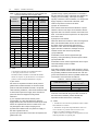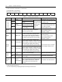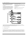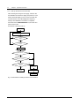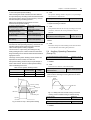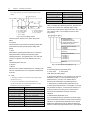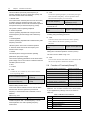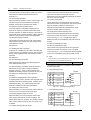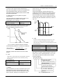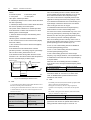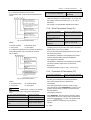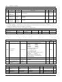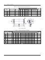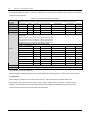
1
EV2000 Series Universal Variable Speed Drive
User Manual
Version: 2.0
Revision date: May 17, 2005
BOM: 31011071
Emerson Network Power provides customers with technical support. Users may
contact the nearest Emerson local sales office or service center.
Copyright © 2005 by Emerson Network Power Co., Ltd.
All rights reserved. The contents in this document are subject to change without
notice.
Emerson Network Power Co., Ltd.
Address: No.1 Kefa Rd., Science & Industry Park, Nanshan District 518057,
Shenzhen China
Homepage: www.emersonnetworkpower.com.cn
Customer Service Hotline: 800-820-6510, (86) 21-23017141,(86) 755-86011668
E-mail: [email protected]
Contents
Preface................................................................................................................................................................................ 1
Unpacking Inspection................................................................................................................................................... 1
Model designation rules ............................................................................................................................................... 1
Chapter 1 Safety............................................................................................................................................................... 2
1.1 Safety .................................................................................................................................................................. 2
1.2 Notes for Installations .......................................................................................................................................... 2
1.3 Notes for Using EV2000 ...................................................................................................................................... 2
1.3.1 About Motor and Load .................................................................................................................................. 2
1.3.2 About Variable Speed Drive.......................................................................................................................... 3
1.4 Disposing Unwanted Drive .................................................................................................................................. 4
Chapter 2 Product Introduction......................................................................................................................................... 5
2.1 Specifications ...................................................................................................................................................... 5
2.2 Product Series ..................................................................................................................................................... 7
2.2.1 Ratings.......................................................................................................................................................... 7
2.2.2 Parts of Variable Speed Drive....................................................................................................................... 8
2.2.3 Outline and Gross Weight ............................................................................................................................. 8
2.3 Optional Parts.................................................................................................................................................... 12
2.3.1 LCD Operational Panel ............................................................................................................................... 12
2.3.2 Braking Kits................................................................................................................................................. 12
2.3.3 Communication Parts.................................................................................................................................. 14
Chapter 3 Installation and Wiring.................................................................................................................................... 15
3.1 Installation Environment .................................................................................................................................... 15
3.2 Removing and Mounting of Parts ...................................................................................................................... 15
3.2.1 Removing and Installation of Operation Panel ............................................................................................ 15
3.2.2 Removing and Mounting of Cover............................................................................................................... 16
3.3 Wire Connections of Drive................................................................................................................................. 17
3.3.1 Wire Connections of Main Terminals .......................................................................................................... 17
3.3.2 Wiring of Control Circuit .............................................................................................................................. 22
3.4 Installation Methods Compliant With EMC Requirements ................................................................................. 31
3.4.1 Noise Suppressing...................................................................................................................................... 31
3.4.2 Field Wire Connections ............................................................................................................................... 32
3.4.3 Earthing ...................................................................................................................................................... 33
3.4.4 Installation Requirements of Relay, Contactor and Electro-magnetic Braking Kit ....................................... 34
3.4.5 Leakage Current ......................................................................................................................................... 34
3.4.6 Correct EMC Installation ............................................................................................................................. 34
3.4.7 Application of Power Line Filter................................................................................................................... 35
3.4.8 EMI of The Drive ......................................................................................................................................... 36
Chapter 4 Operation Instructions.................................................................................................................................... 37
4.1 Notice ................................................................................................................................................................ 37
4.1.1 The Drive’s Control Modes.......................................................................................................................... 37
4.1.2 Reference Selector ..................................................................................................................................... 37
4.1.3 Operating Status ......................................................................................................................................... 37
4.1.4 Operating Modes ........................................................................................................................................ 37
4.2 Operating Instructions ....................................................................................................................................... 38
4.2.1 Using Operation Panel................................................................................................................................ 38
4.2.2 Function of Keys ......................................................................................................................................... 39
4.2.3 Function Descriptions of LED and Indicators .............................................................................................. 39
4.2.4 Display of the Drive..................................................................................................................................... 40
4.2.5 Panel Operation .......................................................................................................................................... 40
4.3 Start-up.............................................................................................................................................................. 41
4.3.1 Checking before Start-up ............................................................................................................................ 41
4.3.2 Start up the Drive for the First Time ............................................................................................................ 42
Chapter 5 Parameter Introductions................................................................................................................................. 43
5.1 Basic Operating Parameters(Group F0) ............................................................................................................... 43
5.2 Parameters of Reference Frequency (Group F1) .............................................................................................. 46
5.3 Starting and Braking Parameters (Group F2) .................................................................................................... 47
5.4 Auxiliary Operating Parameters (Group F3) ...................................................................................................... 49
5.5 PLC Operating Parameters(Group F4)................................................................................................................... 52
5.6 Close-loop Control Parameters(Group F5)................................................................................................................. 55
5.7 Traverse Operating Parameters (Group F6)...................................................................................................... 58
5.8 Function of Terminals(Group F7)....................................................................................................................... 60
5.9 Display (Group F8) ............................................................................................................................................ 69
5.10 Enhanced Functions(Group F9) ...................................................................................................................... 70
5.11 Reserved (Group FA) ...................................................................................................................................... 76
5.12 Communication Parameters (Group FF) ................................................................................................................ 76
5.13 Motor Parameters (Group FH)......................................................................................................................... 77
5.14 Protective Function (Group FL) ....................................................................................................................... 78
5.15 Drive Parameters (Group Fn) .......................................................................................................................... 81
5.16 Protection of Parameters (FP) ......................................................................................................................... 81
Chapter 6 Troubleshooting ............................................................................................................................................. 83
Chapter 7 Maintenance .................................................................................................................................................. 88
7.1 Daily Maintenance ............................................................................................................................................. 88
7.2 Periodical Maintenance ..................................................................................................................................... 88
7.3 Replacing Wearing Parts................................................................................................................................... 89
7.4 Storage.............................................................................................................................................................. 89
7.5 Warranty............................................................................................................................................................ 89
Appendix 1
Parameters .................................................................................................................................................. 90
Appendix 2
Accessories ............................................................................................................................................... 108
Appendix 3 Communication Protocol............................................................................................................................ 111
1 Networking Mode................................................................................................................................................ 111
2 Interfaces............................................................................................................................................................ 111
3 Communication Modes....................................................................................................................................... 111
4 Protocol Format .................................................................................................................................................. 112
5 Explanations of Format....................................................................................................................................... 112
5.1 Head of Frame................................................................................................................................................ 112
5.2 Address of Slave ............................................................................................................................................ 113
5.3 Response of Slave to Master’s Command ..................................................................................................... 113
5.4 Index Section.................................................................................................................................................. 114
5.5 Checksum ...................................................................................................................................................... 114
5.6 Frame Tail ...................................................................................................................................................... 114
Preface
Preface
Thank you for using EV2000 series Variable Speed
Drive made by Emerson Network Power Co., Ltd..
EV2000 satisfies the high performance requirements by
using a unique control method to achieve high torque,
high accuracy and wide speed-adjusting range. Its
anti-tripping function and capabilities of adapting to
severe power network, temperature, humidity and dusty
environment exceed those of similar product made by
other companies, which improves the product’s reliability
noticeably;
Model designation rules
EV2000 -4 T 0055 G / 0075 P
Drive series
Volt
Code
220V
380V
2
4
T
EV2000 has integrated the general requirements,
customized requirements and industrial requirements
perfectly. It is a innovative product with practical PI,
simple PLC, flexible input and output terminals, pulse
signal input, saving parameters at stop or power outage,
master/slave reference control, traverse operation, fixed
length control. It provides OEM customers with high
integrated, reliable, cost-effective solution;
EV2000 can satisfy the customers’ requirements on low
noise and EMI by using optimized PWM technology and
EMC design.
This manual provides information on installation, wiring,
parameter setting, trouble-shooting, and daily
maintenance. To ensure the correct installation and
operation of the drive, please read this manual carefully
before starting the drive and keep it in a safe place.
Unpacking Inspection
Upon unpacking, please check for:
Any damage occurred during transportation;
Check whether the rated values on the nameplate of the
drive are in accordance with your order.
G
P
Fixed torque
Fan & pump
Code
Input volt Code
3-phase
Drive type
Code
Motor power
kW
0055
0075
0110
0150
0185
0220
0300
0370
0450
0550
0750
0900
1100
1320
1600
2000
2200
2800
5.5
7.5
11
15
18.5
22
30
37
45
55
75
90
110
132
160
200
220
280
Fig. A-1 Explanations of Drive Models
The nameplate is located on the right hand side of the
heatsink. The contents are shown in Fig.A-2. A barcode
on the plastic cover also contains the information of the
drive, as shown in Fig.A-3.
MODEL:
EV2000-4T0055G/0075P
model
POWER:
5.5kW/7.5kW
motor power
INPUT:
3PH AC 380V-440V 15.5/20.5A 50Hz/60Hz
OUTPUT: 8.5/11KVA 13/17A 0-650Hz 0-440V
S/N:
barcode
Emerson Network Power Co., Ltd.
Fig. A-2 Nameplate Description
Our product is manufactured and packed at factory with
great care. If there is any error, please contact us or
distributors.
Barcode
The user manual is subject to change without notifying
the customers due to the continuous process of product
improvements.
Nameplate
Fig. A-3 Locations of Nameplate and Barcode
EV2000 Series Universal Variable Speed Drive User Manual
1
2
Chapter 1
Safety
Chapter 1
1.1
!
! Attention
Safety
Danger
! Attention
1.2
Safety
Operations without following
instructions can cause personal
injury or death.
Operations without following
instructions can cause personal
injury or damage to product or other
equipment.
Notes for Installations
·Don’t carry the drive by its cover. The cover cannot
support the weight of the drive and may drop.
·Please install the drive on a strong support, failing
which the drive may fall off.
·Don’t install the drive in places where water pipes
may leak onto it.
·Don't allow screws, washers and other metal foreign
matters to fall inside the drive, otherwise there is a
danger of fire or damage;
·Don't operate the drive if parts are not complete,
!
otherwise there is a danger of a fire or human injury;
Danger
·Don't install the drive under direct sunshine,
·Please install the drive on fire-retardant material.
otherwise it may be damaged;
·Keep the drive away from combustible materials
·Don’t short circuit P1/PB and terminal (-), otherwise
·Keep the drive away from explosive gas
there is a danger of fire or the drive may be
damaged.
·Only qualified personnel shall wire the drive
·Never wire the drive unless the input AC supply is
totally disconnected
·The drive must be properly earthed to reduce
electrical accident
·Install the cover before switching on the drive, to
reduce the danger of electric shock and explosion.
·For drives that have been stored for longer than 2
years, increase its input voltage gradually before
supplying full rated input voltage to it, in order to
avoid electric shock and explosion
·Cable lugs must be connected to main terminals
firmly
· Don’s apply supply voltage (AC 220V or higher) to
control terminals except terminals TA, TB and TC.
1.3
Notes for Using EV2000
Pay attention to the following issues when using EV2000
drive.
1.3.1 About Motor and Load
·Don't touch the live control terminals with bare
hands
Compared to the power frequency operation
·Don’t operate the drive with wet hands
EV2000 series drives are voltage type variable speed
drive. The output voltage is in PWM wave with some
harmonics. Therefore, temperature rise, noise and
vibration of motor are higher.
·Perform the maintenance job after confirming that
the charging LED is off or the DC Bus voltage is
below 36V.
·Only trained professionals can change the
components, it is prohibited to leave wires or metal
parts inside the drive so as to avoid the risk of fire.
·Parameter settings of the control board that has
been changed must be revised, otherwise accidents
may occur.
Low Speed Rotating with Constant Torque
Driving a common motor at low speed for a long time,
the drive’s life will be reduced due to the deteriorating
heat dissipation effect, so a special variable frequency
motor is needed if long time operation with constant
torque is required.
·The bare portions of the power cables must be bound
Motor’s over-temperature protecting threshold
with insulation tapes.
The drive can protect the motor from over-temperature.
If the ratings of the driven motor are not in compliance
EV2000 Series Universal Variable Speed Drive User Manual
Chapter 1
with the drive, be sure to adjust the protective threshold
to ensure the motor is properly protected.
Safety
3
1.3.2 About Variable Speed Drive
Varistors or Capacitors Used to Improve the Power
Factor
Operate above 50Hz
When running the motor above 50Hz, there will be
increase in vibration and noise. The rate at which the
torque is available from the motor is inversely
proportional to its increase in running speed. Ensure that
the motor can still provide sufficient torque to the load.
Lubrication of mechanical devices
Over time, the lubricants in mechanical devices, such as
gear box, geared motor, etc. when running at low speed,
will deteriorate. Frequent maintenance is recommended.
Braking Torque
Braking torque is developed in the machine when the
drive is hoisting a load down. The drive will trip when it
cannot cope with dissipating the regenerative energy of
the load. Therefore, a braking unit with proper
parameters setting in the drive is required.
Don't connect any varistor or capacitor to the output
terminals of the drive, because the drive's output voltage
waveform is pulse wave, otherwise tripping or damaging
of components may occur; in addition, don't install circuit
breaker or contactor at the output side of the drive as
shown in Fig.1-2.
EV2000
U
V
M
W
Fig. 1-2 Capacitors are prohiBited to be used.
The mechanical resonance point of load
The drive system may encounter mechanical resonance
with the load when operating within certain band of
output frequency. Skip frequencies have been set to
avoid it.
The drive should be started and stopped via its control
terminals. It is prohibited to start and stop the drive
directly through input line contactors, which may
damage the drive with frequent operations.
Insulation of Motors
Before using the drive, the insulation of the motors must
be checked, especially, if it is used for the first time or if
it has been stored for a long time. This is to reduce the
risk of the Drive from being damaged by the poor
insulation of the motor. Wiring diagram is shown in Fig.
1-1. Please use 500V insulation tester to measure the
insulating resistance. It should not be less than 5MΩ.
Motor
Mega-Ohm-Meter
Earthing
conductor
Fig. 1-1 Checking the insulation of motor
Circuit breakers connected to the output of the drive
If circuit breaker or contactor needs to be connected
between the drive and the motor, be sure to operate
these circuit breakers or contactor when the drive has
no output, to avoid damaging of the drive.
Using outside the range of rated voltage
The drive is not suitable to be used out of the specified
range of operation voltage. If needed, please use
suitable voltage regulation device.
Change from 3-phase to 2-phase
It is not recommended to change the drive from 3-phase
input to 2-phase input. If it is necessary to use on two
phases, the phase-loss protection function of the drive
should be disabled. The Drive must be derated for this
operation. For motors at which power is above 30kW, if
it is changed into 2-phase input, then the input phases
must be at phase R and phase T, or else the drive will
not work.
After the 3-phase input is changed into 2-phase input,
bus-voltage and current ripple may increase, which not
only influences the life of electrolytic capacitor but it also
deteriorates the performance of the drive. The drive’s
operating current should be derated and should not
exceed 67% of rated value.
Protection against lightning strike
There are transient surge suppressors inside the Drive
which protects it against lighting strike.
EV2000 Series Universal Variable Speed Drive User Manual
4
Chapter 1
Safety
Derating due to Altitude
1.4
Derating must be considered when the drive is installed
at high altitude, greater than 1000m. This is because the
cooling effect of Drive is deteriorated due to the thin air,
as shown in Fig.1-3 that indicates the relationship
between the elevation and rated current of the Drive.
Iout
100%
Disposing Unwanted Drive
When disposing the Drive, pay attention to the following
factors:
The capacitors may explode when they are burnt.
Poisonous gas may be generated when the plastic parts
like front covers are burnt.
Disposing method: Please dispose the Drive as
industrial waste.
90%
80%
1000
2000
3000
4000 (m)
Fig. 1-3 Derating Drive's output current with altitude
EV2000 Series Universal Variable Speed Drive User Manual
Chapter 2
Chapter 2
2.1
Product Introduction
5
Product Introduction
Specifications
Table 2-1 General specifications
Item
Input
Description
Rated voltage & frequency
Three-phase,380V~440V; 50Hz/60Hz
Permissible fluctuation range
Voltage:320V~460V;Voltage unbalance rate:<3%; Frequency:±5%
Rated voltage
380V
Frequency
0Hz~650Hz
Over load ability
Type G: 150% rated current for 1 minute, 200% rated current for 0.5
second;
Type P: 110% rated current for 1 minute, 150% rated current for 1
second
Modulation mode
Flux vector PWM modulation
Speed range
1:100
Starting torque
180% rated torque at 0.50Hz
Steady accuracy of speed
≤±0.5% rated synchronous speed
Output
Accuracy of frequency
Main control
functions
Digital setting: highest frequency×±0.01%;analog setting: highest
frequency×±0.2%
Setting frequency resolution
Digital setting:0.01Hz;analog setting: highest frequency×0.1%
Torque boost
Auto torque boost, Manual torque boost0.1%~30.0%
V/F curve
4 modes: 1 V/F curve mode set by user and 3 kinds of torque-derating
modes (2.0 order, 1.7 order, and 1.2 order)
Acc/Dec curve
3 modes: linear Acc/Dec, S ramp Acc/Dec and auto Acc/Dec; Acc/Dec
time(maximum: 60 hours) and unit(second or minute) are settable.
DC injection braking
Initial frequency of DC injection braking process: 0.20~60.00Hz,
braking time: 0.0~30.0s
braking current: Type G: 0.0~100.0%
Type P: 0.0~80.0%
Jog
Range of jog frequency:0.20Hz~50.00Hz; Acc/Dec time of Jog operation:
0.1~60.0s, Interval of Jog operation is also settable.
Multi-step speed running
Multi-step speed running can be realized by internal PLC or control
terminal
Internal PI
Be able to form simple control system easily
Auto-energy saving operation
V/F curve is optimized automatically according to the load condition to
realize energy-saving operation.
Auto voltage regulation(AVR)
When source voltage changes, the modulation rate can be adjusted
automatically, so that the output voltage is unchanged.
Auto current limiting
Operating current is limited automatically to avoid frequent tripping of the
drive.
Auto adjusting of carrier
frequency
Optional function. The carrier frequency can be adjusted automatically
according to the load condition.
EV2000 Series Universal Variable Speed Drive User Manual
6
Chapter 2
Product Introduction
Item
Customized
function
Operating
function
Operation
panel
Description
Traverse operation
Traverse operating function with adjustable central frequency
Fixed-length control
The drive stops when preset fixed length is reached
Droop control
Used in the application that several drives drive one motor.
Tone adjusting
Adjust the tone of the operating motor
Non-stop operation upon power Uninterrupted operation can be realized by controlling the bus voltage
failure
when power failure occurs.
Bundling function
Control mode and reference selector (for example panel input or analog
VCI input) can be selected together at one time
Methods of inputting operating
commands
Commands can be input by terminals and serial ports.
Methods of setting up
frequency
Digital setting; Analog voltage/current setup; pulse frequency setup; set
via serial port and different setting modes are selectable
Auxiliary frequency reference
Realize flexible fine tuning of auxiliary frequency.
Pulse output terminal
0~50kHz pulse signal output. Signals like frequency setting and output
frequency can be output.
Analog output terminals
2 analog outputs of 0/4~20mA and 0/2~10V(selectable). Be able to
output signals like reference frequency and output frequency.
LED display
Be able to display about 20 kinds of parameters such as frequency
setting, output frequency, output voltage and current, etc.
LCD display
Optional, Chinese/English display
Parameter copy
Fast parameter copy can be realized by using LCD panel.
Keys locking up and function
selection
Be able to lock part or all the keys. Be able to define the functions of part
of the keys to avoid wrong operation.
Protection function
Phase failure protection, Over current protection; Over voltage protection;
Under voltage protection; Over heat protection; overload protection
Optional parts
LCD operation panel, braking kit, remote mounted keypad, remote control
cable and field bus adapter
Environment
Structure
Application environment
In-door, free from direct sunlight, dust, corrosive gas, combustible gas, oil
mist, steam, water drop or salt
Elevation
Lower than 1000m
Ambient temperature
-10℃~+40℃(ambient temperature is within 40℃~50℃, deration is
required)
Humidity
Less than 95%RH, without condensation
Vibration
2
Less than 5.9m/s (0.6g)
Storage temperature
-40℃~+70℃
Protection level
IP20
Cooling
Fan cooling
Mount modes
Mounted on the wall or inside cabinet
Efficiency
For 45kW or below: ≥93%, 55kW or above: ≥95%
EV2000 Series Universal Variable Speed Drive User Manual
Chapter 2
2.2
Product Introduction
Product Series
2.2.1 Ratings
Table 2-2 Variable Speed Drive series(55P or below)
Drive model (55P or below)
Rated capacity
Rated input current Rated output current
(G: constant torque, P: Fan & pump)
(kVA)
(A)
(A)
EV2000-4T0055G/0075P
8.5/11
15.5/20.5
13/17
EV2000-4T0075G/0110P
11/17
20.5/26
17/25
Motor power
(kW)
5.5/7.5
7.5/11
EV2000-4T0110G/0150P
17/21
26/35
25/32
11/15
EV2000-4T0150G/0185P
21/24
35/38.5
32/37
15/18.5
EV2000-4T0185G1/0220P1
24/30
38.5/46.5
37/45
18.5/22
EV2000-4T0220G1/0300P1
30/40
46.5/62
45/60
22/30
EV2000-4T0300G1/0370P1
40/50
62/76
60/75
30/37
EV2000-4T0370G1/0450P1
50/60
76/92
75/90
37/45
EV2000-4T0450G1/0550P1
60/72
92/113
90/110
45/55
Table 2-3 Variable Speed Drive series(55G or above)
Drive model (55G or above)
Rated
Rated input current
Rated output current
capacity
(A)
(A)
Constant torque
Fan & pump
(kVA)
-
EV2000-4T0550G
72
113
110
Motor power
(kW)
55
EV2000-4T0750G
EV2000-4T0750P
100
157
152
75
EV2000-4T0900G
EV2000-4T0900P
116
180
176
90
EV2000-4T1100G
EV2000-4T1100P
138
214
210
110
EV2000-4T1320G
EV2000-4T1320P
167
256
253
132
EV2000-4T1600G
EV2000-4T1600P
200
307
304
160
EV2000-4T2000G
EV2000-4T2000P
250
385
380
200
EV2000-4T2200G
EV2000-4T2200P
280
430
426
220
-
EV2000-4T2800P
342
525
520
280
Notes:
1. Models in shady area are under development.
2. Please contact the manufacturer for models of EV2000-4T2800G and EV2000-4T3150P.
EV2000 Series Universal Variable Speed Drive User Manual
7
8
Chapter 2
Product Introduction
2.2.2 Parts of Variable Speed Drive
Cover
Port for operation
panel
Multi-function
terminal
Cover's
mounting hole
Control
board
Compartment for
operation panel
Control terminal
Barcode
Charge
indicator
Power terminal
shielding
board
Mounting
hole
Inlet holes for
signal cables
Power
terminal
Outlet holes for
AC output holes
Nameplate
Ventilation
holes
Fig. 2-1 Parts of drive
2.2.3 Outline and Gross Weight
1. Outline
Fig. a EV2000-4T0055G/0075P~
EV2000-4T0150G/0185P
Fig. b EV2000-4T0185G1/0220P1~
EV2000-4T0220G1/0300P1
EV2000 Series Universal Variable Speed Drive User Manual
Chapter 2
Fig. c EV2000-4T0300G1/0370P1~
EV2000-4T0450G1/0550P1
Fig. d EV2000-4T0550G~
Product Introduction
Fig. e EV2000-4T01100G~
EV2000-4T01100P
Fig. 2-2 Outline of EV2000
EV2000 Series Universal Variable Speed Drive User Manual
EV2000-4T2800P
9
10
Chapter 2
Product Introduction
2. Mechanical parameters
Table 2-4 Mechanical parameters 1
EV2000-4T0055G/0075P~EV2000-4T0450G1/0550P1、EV2000-4T0550G、EV2000-4T0750G、EV2000-4T0750P、
EV2000-4T0900P、EV2000-4T0900G、EV2000-4T1100P
Drive model (55P or below)
(G: constant torque, P: Fan & pump)
Motor
A
B
H
W
D
(kW) (mm) (mm) (mm) (mm) (mm)
EV2000-4T0055G/0075P
5.5/7.5
EV2000-4T0075G/0110P
7.5/11
EV2000-4T0110G/0150P
11/15
EV2000-4T0150G/0185P
15/18.5
EV2000-4T0185G1/0220P1
18.5/22
EV2000-4T0220G1/0300P1
22/30
EV2000-4T0300G1/0370P1
30/37
EV2000-4T0370G1/0450P1
37/45
EV2000-4T0450G1/0550P1
45/55
EV2000-4T0550G
_
EV2000-4T0750G EV2000-4T0750P
Diameter of
Fig.
Gross
mounting
Number weight(kg)
hole(mm)
186
285
300
200
202
6.8
Fig. a
7.5
236
365
380
250
209
6.8
Fig. a
12
180
421
435
275
209
7
Fig. b
250
600
624
375
262
9
Fig. b
13
15
35
38
55
300
747
770
468
301
10
Fig. d
50
75
300
747
770
468
301
10
Fig. d
50
EV2000-4T0900G EV2000-4T0900P
90
300
747
770
468
301
10
Fig. d
90
EV2000-4T1100P
110
300
747
770
468
301
10
Fig. d
90
Table 2-5 Mechanical parameters 1
EV2000-4T1100G~EV2000-4T2200G. EV2000-4T2200P. EV2000-4T2800P
Drive model
Constant torque
Fan & pump
EV2000-4T1100G
-
Diameter of
Motor
A
B
H
W
D
Fig.
Gross
mounting holes
(kW) (mm) (mm) (mm) (mm) (mm)
Number weight (kg)
(mm)
110
370
855
880
530
370
14
100
EV2000-4T1320G EV2000-4T1320P
132
370
855
880
530
370
14
100
EV2000-4T1600G EV2000-4T1600P
100
160
370
855
880
530
370
14
-
EV2000-4T2000P
200
370
855
880
530
370
14
EV2000-4T2000G
-
200
520
975 1000 680
370
14
140
220
520
975 1000 680
370
14
140
280
520
975 1000 680
370
14
140
EV2000-4T2200G EV2000-4T2200P
-
EV2000-4T2800P
Fig. e
100
Notes:
1. Models in Table 2-5 are under developing.
2. For 75kWG drive or above, DC reactor is included in its standard configuration. The weight of DC reactor in the above table is
not included in the gross weight. Outline and dimensions of DC reactor are shown below.
EV2000 Series Universal Variable Speed Drive User Manual
Chapter 2
Product Introduction
11
Diameter of terminal
Enlarged view of terminal
Mounting hole
Mounting hole
Fig. 2-3 Dimensions of DC reactor
Applicable
drive
(kW)
75G
Model of DC
reactor
Table 2-6 Mechanical Parameters of DC Reactor
Recommended
Size(mm)
size of copper
A
B
C
D
E
F
G
H
(mm2)
I
J
Gross
Diameter weight
of terminal (kg)
TDL-4DI01-0900
60
190 160 125 161 120
80
10
250 280
25
φ12
23
110G/110P TDL-4DI01-1100
100
190 160 125 161 120
80
10
250 280
25
φ12
25
132G/132P TDL-4DI01-1320
150
200 170 135 171 120
85
10
260 280
30
φ12
28
160G/160P TDL-4DI01-1600
150
210 180 135 171 130 85
12
280 320
30
φ12
32
200G/200P
200
220 190 135 171 150 90
12
315 340
40
φ15
40
220 190 145 181 160
12
315 340
40
φ15
45
90G/90P
220G/220P
280P
TDL-4DI01-2200
TDL-4DI01-2800
250
325
95
Notes:
1. Columns B and C in Table 2-6 are the sizes of mounting holes of DC reactor.
2. DC reactor should be installed at the bottom of the cabinet if it is to be installed inside a cabinet. The clearance between reactor
and the drive should be at least 35cm, and the reactor should be as far away from the air inlet port of the drive as possible.
EV2000 Series Universal Variable Speed Drive User Manual
12
Chapter 2
Product Introduction
3. Optional panel and mounting box
a) Operation panel
b) Mounting box (Model: EVF-KB02)
Fig. 2-4 Operation panel and mounting box
2.3
2.3.2 Braking Kits
Optional Parts
All the optional parts are given below, make additional
orders if needed.
2.3.1 LCD Operational Panel
Model:TDP-LCD03
Language: Chinese/English optional
LCD operation panel can perform fast parameter copy.
Interface: As shown in Fig. 2-5, the interface is divided
into main display area, operation instruction area and
explanations for operation instructions.
1. Braking kit
Braking
kit
Motor
Code power
Volt Code
220V
380V
660V
220V
380V
660V
2
4
6
Explanations for operations: Display the explanations for
the “operation display area”
Freq. Set Mode
E/D Parameter
FREQ SET
E/D DATA SET
Main display area
Operation display area
2
4
6
Braking unit
Fig. 2-6 Model of braking kit
2. Braking resistor
Main display area: Display the status, parameters.
Operation display area: Display the next operation, if
there are several operations for selection, the operation
contents will be displayed in this area one by one.
4C01 0150
TDB
TDB
R01 0015
Braking
Kit
Braking
resistor
0400
Code Resistor
0400
2
0200
4
0100
6
Power Code
1.5kW 0015
3.0kW 0030
5.0kW 0050
Fig. 2-7 Explanations of Model of braking resistor
Main display area
Operation display area
Fig. 2-5 LCD display interface
EV2000 Series Universal Variable Speed Drive User Manual
Chapter 2
Product Introduction
13
3. Configurations
Table 2-7 Specifications of braking kit and resistor
Ratio of working time of
Braking
braking kit to drive’s total
torque (%)
working time (%)
Maximum
continuous
operating time(s)
Model of braking
kit
100
10
Built-in
100
10
Built-in
10
100
10
TDB-4C01-0150
TDB-R01-0015-0400
10
100
10
TDB-4C01-0150
18.5
TDB-R01-0015-0400
10
100
10
TDB-4C01-0150
22
TDB-R01-0030-0200
10
100
10
TDB-4C01-0300
30
TDB-R01-0030-0200
10
100
10
TDB-4C01-0300
37
TDB-R01-0030-0200
10
100
10
TDB-4C01-0300
45
TDB-R01-0050-0100
10
100
10
TDB-4C01-0550
55
TDB-R01-0050-0100
10
100
10
TDB-4C01-0550
75
TDB-R01-0050-0100
10
100
10
TDB-4C01-0550
Rated motor
power(kW)
Model of braking
resistor
5.5
-
10
7.5
-
10
11
TDB-R01-0015-0400
15
Notes
1. There is a braking kit inside the 7.5kW drive or below. An external braking resistor is needed to be connected if dynamic
braking is required and the recommended resistor is 1000W/100Ω.
2. The 90kW drive or above should use several braking kits connected in parallel (TDB-4C01-0550).
4. Outline and installation sizes
Fig. 2-8 Installation dimensions of braking kit
Table 2-8 Installation dimensions of braking kit(unit: mm)
Model of braking
Gross
A
B
C
D
E
kit
weight
TDB-4C01-0150 254 143 144 240 100
3 kg
TDB-4C01-0300 254 143 144 240 100
3 kg
TDB-4C01-0550 254 130 170 240 126
4 kg
Fig. 2-9 Installation dimensions of braking resistor
Table 2-9 Installation dimensions of braking resistor
(unit: mm)
Model of braking
resistor
A
B
C
D
E
F
Gross
weight
TDB-4R01-0015-0400 475 228 127 447 177 460 3 kg
TDB-4R01-0030-0200 500 350 128 480 298 490 6 kg
TDB-4R01-0050-0100 540 520 170 520 470 530 8 kg
5. Functions and wiring
A. Wire connections braking resistor and braking kit
EV2000 Series Universal Variable Speed Drive User Manual
14
Chapter 2
Product Introduction
EV2000
U
V
R
W
S
T
M
PE
(-)
(+)
PR
P
N
TA
TB
TC
braking unit
P
TH1
TH2
PR
braking resistor
Fig. 2-10 Connecting the braking kit to the Drive
TA-TB and TA-TC are contacts of relay used for
outputting fault indicating signal, and TH1 and TH2 are
contacts of temperature relay (relay used for outputting
over-heat indicating signal).
B. Main functions of braking kit
Activation voltage for braking is adjustable;
Protection against excessive duty-cycle of braking
resistor;
Overheat protection of heatsink;
Alarm indication for power module’s fault;
Fault indication and indication for fault relay output;
The braking resistor will be disconnected automatically if
it is over-heated and the relay will output alarming
signal.
The cables connected between the braking kit and the
drive, and those between the braking kit and braking
resistor should be less than 5m. If longer than 5m,
twisted-pair cable should be used and the maximum
length is 10m.
RS485 communication mode is used between the drive
and the remote mounted keypad. A 4-core cable is used
to connect the drive and the keypad, and the maximum
distance can be 1000m. Master/slave communication
mode is used. The keypad is the master and the drive is
the slave. Cable terminals can be secured by common
screws, which makes it convenient for maintenance.
One remote mounted keypad can control several drives
by connecting the communication cables of 485+ and
485- of each drive to form a RS485 network.
Functions:
1) Be able to control the start, stop, jog operation, fault
reset of slave drives and change the frequency settings
and operation direction.
2) Identify the type of slave machine automatically. Be
able to monitor the operating frequency, frequency
setting, output voltage and current, analog close-loop
feedback, analog close-loop setting and external
counting value automatically.
3. Fieldbus adapter
Model: TDS-PA01
Be able to connect ENYDRIVE drive to PROFIBUS
network via the TDS-PA01 fieldbus adapter. In the
PROFIBUS network system, the drive operates as a
slave.
Functions:
1) To send control commands to drive (such as: start,
stop and jog);
2) To send speed or frequency reference signal to the
drive;
3) To read operating status information and actual
values from the drive;
2.3.3 Communication Parts
4) To reset the drive when fault occurs in it.
1. Communication cables
4. DrvWindows host monitoring software
A. Cables of operation panel
Version: DrvWindows V1.2
Model: TDC-CB0015(1.5m)
TDC-CB0030(3.0m)
The cables are used to connect the panel to the drive.
B. Communication cables of remote mounted keypad
Two models: FRC21W1(3.0m) FRC21W2(30m)
The cables are used to connect the remote mounted
keypad to the drive.
2. Remote mounted keypad
Model: TDO-RC02
It uses the same structure with operation panel of the
drive. It is easily to be installed and secured and
convenient for hand-held operation. Its display is similar
to the operation panel.
Used in the control network formed by TD1000, TD2000
and TD2100 series drive via RS485 bus. It can monitor
the operating status of the drive connected to the bus
and realize the central management of the drive. The
software’s friendly interfaces make the operation
convenient. This software now support EV2000 drive.
Functions:
Polling of slave drives, frequency setting, operating and
stopping, changing and querying the settings of
parameter.
5. Keypad Holder
Model: EVF-KB02
EV2000 Series Universal Variable Speed Drive User Manual
Chapter 3
Chapter 3
3.1
Installation and Wiring
Installation and Wiring
Installation Environment
Please mount the drive vertically inside a well-ventilated
location.
When selecting mounting environment, the following
issues should be taken into account:
Ambient temperature should be within the range of
-10℃~40℃. If the temperature is higher than 40 ℃, the
35cm
or above
air expulsion by
fan
15cm
or
above
15cm
or
above
drive should be derated and forced ventilation is
required;
35cm
or above
Humidity should be lower than 95% non-condensing
Mount in the location where vibration is less than
5.9m/s2 (0.6G);
Fig. 3-2 Installation clearance(55kW or above)
Mount in the location free of direct sunlight, dust, metal
powder, corrosive gas or combustible gas.
If there are any special requirements for installation,
please contact us for clarifications.
The requirements on mounting space and clearance are
shown in Fig. 3-1 and Fig. 3-2.
Drive
When two Variable Speed Drives are mounted one on
top the other, an air flow diverting plate should be fixed
in between as shown in Fig. 3-3.
air expulsion by fan
10cm
or above
5cm
or
above
Drive
5cm
or
above
Fig. 3-3 Installation of several drives
3.2
10cm
or above
Removing and Mounting of Parts
3.2.1 Removing and Installation of Operation Panel
Fig. 3-1 Installation clearance (45kW or below)
1. Disassembly
Put your middle finger into the hole on the top of
operation panel, press down the snapper and pull the
panel outward as shown in. Figure 3-4.
2. Installation
Place the bottom edge of the operation panel at the
hooks of the mounting groove and press down the
EV2000 Series Universal Variable Speed Drive User Manual
15
16
Chapter 3
Installation and Wiring
snapper with your middle finger. Then press the panel
inward to snap it in position as shown in Figure 3-4.
②Insert the top clamp into the slot at the top of the
drive;
③Mount the screws at the bottom part of the cover;
④Install the operation panel
1
Fig. 3-5 Removing and installation of plastic cover
Note:
Pull out or insert the plastic cover gently, otherwise the
mounting clamp may be damaged.
2. Procedures of removing and mounting the metal
cover
3
1) Procedures of removing the metal cover:
2
①Remove the operational panel;
②Remove all the screws on the cover;
Fig. 3-4 Removing and Mounting of Operation Panel
Where: 1&2: holding clamp
3:panel
3.2.2 Removing and Mounting of Cover
③Take out the cover horizontally.
2) Procedures of installing the metal cover:
①Mount the cover on the frame by screws;
②Install the operation panel.
EV2000 series have two kinds of cover, plastic or
metallic one. Follow the steps below to remove and
mount the cover.
1. Removing and mounting of plastic covers
1) Removing:
① Remove the operation panel
② Remove two screws at bottom
③ Lift the bottom of cover up to 5~10 degrees, move it
upward at least 10mm until the clamp are out of the slot
on the cabinet, then remove the front panel.
2) Mounting of plastic cover:
①Tilt the cover 5~10 degree;
Fig. 3-6 Removing and mounting metal cover
EV2000 Series Universal Variable Speed Drive User Manual
Chapter 3
3.3
Wire Connections of Drive
! Danger
QF
3-phase
AC
supply
Installation and Wiring
R
S
U
V
EV2000
W
PE
T
·Wiring can only be done after the drive’s AC
. VRF
. VCI
. CCI
. GND
power is disconnected, all the LEDs on the
operation panel are off and waiting for at least 5
minutes. Then, you can remove the panel.
·Wiring job can only be done after confirming the
charge indicator on the right bottom has
extinguished and the voltage between main circuit
power terminals + and - is below DC36V.
17
M
.
REV .
COM .
FWD
Fig. 3-7 Wiring
·Wire connections can only be done by trained and
3.3.1 Wire Connections of Main Terminals
authorized personnel.
·Check the wiring carefully before connecting
emergency stopping or safety circuits.
·Check the drive’s voltage level before supplying
power to it, otherwise human injuries or equipment
damage may happen.
1. Connection between drive and optional parts
R
S
T
N
Isolator switch
Circuit breaker or
fuse
AC input reactor
! Attention
·Check whether the Variable Speed Drive’s rated
input voltage is in compliant with the AC supply
voltage before using.
Contactor
Input EMI filter
·Dielectric strength test of the drive has been done
in factory, so you need not do it again.
·Refer to chapter 2 on connected braking resistor
or braking kit.
·It is prohibited to connect the AC supply cables to
the drive’s terminals U, V and W.
R S T P1
+
EV2000
PE U V W
-
·Grounding cables should be copper cables with
DC reactor
Braking unit
Braking resistor
section area bigger than 3.5mm2, and the
Output EMI filter
grounding resistance should be less than 10Ω.
AC output reactor
·There is leakage current inside the drive. The total
leakage current is greater than 3.5mA, depending
on the usage conditions. To ensure safety, both the
drive and the motor should be grounded, and a
leakage current protector (RCD) should be
installed. It is recommended to choose B type RCD
and set the leakage current at 300mA.
·The drive should be connected to the AC supply
via a circuit breaker or fuse to provide input
over-current protection or convenience for
disconnecting the AC supply to maintain the drive.
Wire the drive according to Fig. 3-7 during
commissioning :
M
IM
Fig. 3-8 Wire connection between the drive and optional parts
1). Isolation switch should be connected between the
AC supply and the drive to ensure the safety of the
maintenance engineer.
2). Circuit breaker (QF) or fuse should be connected
between the AC supply and the drive to isolate the fault
of other equipment. Refer to Table 3-1 for the selection
of circuit breaker.
3) When a contactor is used for controlling the AC
supply, don’t use it to switch on or off the Variable
Speed Drive.
EV2000 Series Universal Variable Speed Drive User Manual
18
Chapter 3
Installation and Wiring
Table 3-1 Recommended capacity of circuit breaker and
the cross sectional area of copper cable
Input
Main circuit Control circuit
switch
(mm2)
(mm2)
Model
Circuit
EV2000-4T
Input Output
Control
breaker
cable cable
terminal
QF(A)
0055G/0075P
32
4
4
1
(4) When a large capacity transformer is connected to
the drive, the input current of the drive may damage the
rectifying circuit. Generally, if the input AC supply
capacity of the drive is above 550KVA, or if the input AC
supply capacity is 10 times that of the drive, a DC
reactor is required to connect to the drive.
(5) Input AC Line Reactor
0075G/0110P
40
6
6
1
0110G/0150P
63
6
6
1
0150G/0185P
63
6
6
1
0185G/0220P
100
10
10
1
0220G/0300P
100
16
16
1
0300G/0370P
125
25
25
1
0370G/0450P
160
25
25
1
0450G/0550P
200
35
35
1
0550G
200
35
35
1
0750G 0750P
250
70
70
1
0900G 0900P
315
70
70
1
When the cables from the drive to motor are longer than
80m, multi-stranded cables and an AC line reactor
should be used to suppress the high frequency
harmonics. Thus, the motor insulation is protected
against heat due to harmonics, leakage current is
reduced and the drive will not trip frequently.
1100G 1100P
400
95
95
1
(7) Input EMI filter
1320G 1320P
400
150
150
1
1600G 1600P
630
185
185
1
An EMI filter can be used to suppress the high
frequency noise generated by the drive’s power cables.
2000G 2000P
630
240
240
1
(8) Output EMI filter
2200G 2200P
800
150×2 150×2
1
2800P
1000
185×2 185×2
1
An EMI filter can be used to suppress the drive’s output
noise and leakage current of cables.
Note:
1, Parameters in the table are recommended values.
2, The input protection fuses of inverters
EV2000-4T0185G1/ 0220P1 and EV2000-4T0220G1/
0300P1 are respectively the RT16 Series 63A and 80A
products of Xi'an Fusegear Manufacture Company.
4). DC reactor
DC reactor is required for the drive whose power is
greater than EV2000-4T0750G, for the drive whose
power is lower than EV2000-4T0750P, it is optional.
Under following conditions, a DC reactor should be used
to reduce the impact of AC supply to the drive and to
protect the drive and suppress the high-order
harmonics.
(1) If a capacitor tank used for reactive power
compensation or a SCR load shares the same AC
supply with the drive, the harmonics caused by the SCR
load or the capacitor tank when it is switched on or off
may damage the drive’s input rectifying circuit;
(2) When the unbalance rate of 3-phase AC supply of
the drive is greater than 3%;
(3) If the input power factor of the drive is required to be
greater than 0.93;
A line reactor should be used if the distortion of power
network is severe or the input current harmonic level is
high even after a DC reactor has been connected to the
drive. It can also be used to improve the AC input power
factor of the drive.
6) Output AC Line Reactor
(9) Safety ground
Since there is leakage current inside the drive, to ensue
safety, both the drive and the motor should be grounded,
the grounding resistance should be less than 10Ω. The
ground wire should be as short as possible. Please refer
to the section of the earth wire in Table 3-2.
Table 3-2 Section of Ground Wire
Min. section of ground
Cable Section (mm2)
wire Sp(mm2)
S
S≤16
16
16<S≤35
S/2
35<S
Note that the data in the above table apply when the
conductor connected with the ground wire are made of
the same metal, otherwise, please calculate the
equivalent section based on the conductivity.
Notes:
1. EV2000 drive can meet the requirements of IEC 61800-3
after EMI filter is installed.
2. Installation of input and output EMI filters must be as
close to the drive as possible. Refer to Section 3.4 of
Chapter 3 for EMC installation instructions.
3. Refer to Section 2.3 of Chapter 2 and Appendix 2 for the
technical parameters of optional parts.
EV2000 Series Universal Variable Speed Drive User Manual
Chapter 3
Installation and Wiring
2. Wire Connections of Drive for Basic Operation
Models: EV2000-4T0055G/0075P. EV2000-4T0075G/0110P
DCL DC reactor
Braking resistor
(connect optional parts
(connect optional parts
externally)
(+) PB (-) externally)
P1
Breaker
R
3-phase R
380V S
50/60Hz T
U
V
W
PE
S
T
Aux.
Power
supply
P24
PLC
Forward/stop
P24
COM
X7
X8
FWD
Reverse/stop
0/4~20mA
0~10V
X1
Multi-function input 2
Multi-function input 3
Multi-function input 4
Multi-function input 5
Multi-function input 6
Multi-function input 7
Multi-function input 8
Speed command
0~10V
. GND
.
. AO1
X2
X3
X4
CN16
0/4~20mA . AO2
.
0~10V .
P24
X5
CN17 DO
X6
X7
COM
EV2000
X8
COM
DC current
meter
0/4-20mA current
signal
Output 0-24V pulse
signal
Frequency meter
Y1
Output 1
Y2
Output 2
Common terminal
COM
TA
VCI
CCI
.
. I
.
V
GND
CN10
PE
Bi-direction open
collector output
CME
VRF
0~10V/0~20mA
PG
PE
REV
Multi-function input 1
M
TB
TC
Programmable
relay output
485+
RS232 .
.
485-
TXD
RXD
CN14 GND
RS485 .
RS485
communication port
RS232
communication
port
Fig. 3-9 Basic wiring 1
Notes:
1. Terminal CCI can be input voltage or current signal by switching the jumper CN10 on control board;
2. The auxiliary power supply comes from the bus (+) and bus (-);
3. Built-in braking kit is installed and a braking resistor is required to be connected between (+) and PB;
4. In the above figure, “O” is the terminal in main circuit, and “⊙” is the control terminal;
5. Refer to section 3.3.2 for the using of control terminals.
EV2000 Series Universal Variable Speed Drive User Manual
19
20
Chapter 3
Installation and Wiring
Applicable models: EV2000-4T0110G/0150P~EV2000-4T2800P
Braking resistor
or braking unit
DCL DC reactor
(connect externally,optional
parts for 75kW or below)
Breaker
3-phase R
S
380V
50/60Hz T
(+)
P1
(-)
P P
N PB
(Connect optional parts
externally)
R
S
T
U
V
W
PE
M
R0
Aux.
Power
supply
P24
PLC
Forward/stop
T0
P24
COM
X7
X8
FWD
Reverse/stop
PE
REV
Multi-function input1
0/4~20mA
.
0~10V .
Multi-function input3
X3
Multi-function input4
X4
Multi-function input5
AO2
P24
CN17 DO
COM
X7
Multi-function input8
X8
COM
Speed command
0~10V
EV2000
VRF
Output 1
Y2
Output 2
COM
VCI
Programmable
relay output
485+
.
RS232 .
RS485 .
Bi-direction open
collector output
Common terminal
TA
TB
TC
.
.. I
V
GND
CN10
CCI
PE
Frequency meter
Y1
CME
0~10V/0~20mA
0/4-20mA current
signal
Output 0-24V pulse
signal
CN16
X6
Multi-function input7
DC current
meter
AO1
.
0/4~20mA .
.
0~10V
X5
Multi-function input6
GND
.
X1
X2
Multi-function input2
PG
485TXD
RXD
CN14 GND
RS485
communication port
RS232
communication
port
Fig. 3-10 Basic wiring 2
Notes:
1. Terminal CCI can be input voltage or current signal by switching the jumper CN10 on control board;
2. The auxiliary power supply’s AC supply comes from R0 and T0 which are shorted with R and T of 3-phase input. If you want
to use an external AC supply, the shorting bars between R and R0, T and T0 have to be removed before connecting the external
AC supply via R0 and T0. Otherwise, short-circuit will occur.
3. It is prohibited to connect to the control power supply without disconnecting the short-circuit bar, so as to avoid short-circuit
accident;
4. If external braking parts are needed, then braking kit and braking resistors should be included; Pay attention to the polarity of
the braking kit when wiring;
5. In the above figure, “O” is the terminal in main circuit, and “⊙” is the control terminal;
6. Refer to section 3.3.2 for the using of control terminals.
EV2000 Series Universal Variable Speed Drive User Manual
Chapter 3
Installation and Wiring
21
Applicable models: EV2000-4T0185G1/0220P1~EV2000-4T0450G1/0550P1
braking unit and braking
resistor (external, optional)
DCL DC reactor
(external, optional)
buffer resistor
(built-in)
P
breaker
3-phase R
380V
S
50/60Hz
T
P1 (+)
(-)
P P
N PB
U
V
W
PE
R
S
Transistor
T
P24
Auxiliary
power
supply
R0
T0
PLC
Foward/Stop
Reverse/Stop
MS input 1
MS input 2
MS input 3
MS input 4
MS input 5
MS input 6
MS input 7
MS input 8
FWD
REV
0~10V/0~20mA
P24
COM
X7
X8
PG
PE
0/4-20mA
0-10V
X1
.
.
.
GND
AO1
DC current meter
CN16
AO2
0/4-20mA ..
0-10V .
P24
CN17
DO
X2
X3
X4
X5
X6
X7
0/4-20mA current signal
frequency meter (open collector output)
0-24V pulse output signal
COM
EV2000
Y1
output 1
COM
Y2
output 2
VRF
COM
X8
2-way open collector output
CME
Speed instruction
0~10V
M
VCI
CCI
GND
common terminal
TA
TB
.
. I
. V
CN10
Programmable relay output
TC
485+
PE
RS232 .
.
RS485 .
485TXD
RXD
CN14 GND
Standard RS485 port
Standard RS232 port
Fig. 3-11 Basic Wiring 3
Notes:
1. Terminal CCI can be input voltage or current signal by switching the jumper CN10 on control board;
2. The auxiliary power supply of EV2000-4T0185G1/0220P1~EV2000-4T0220G1/0300P1 is from bus (+) and (-)。
3. The auxiliary power supply of EV2000-4T0300G1/0370P1~EV2000-4T0450G1/0550P1 is from R and T. If you want to use
an external AC supply, the jumper on CN4 should be connected to CN3 first, and then connect it to R0 and T0.
4. If external braking kit, the braking unit and braking resistors should be included; Pay attention to the polarity of the braking kit
when wiring;
5. In the above figure, “O” is the terminal in main circuit, and “⊙” is the control terminal;
6. Refer to section 3.3.2 for the usage of control terminals.
EV2000 Series Universal Variable Speed Drive User Manual
22
Chapter 3
Installation and Wiring
3. Input/Output Terminals in Main Circuit
Terminal
1) Applicable models:
EV2000-4T0055G/0075P~EV2000-4T0150G/0185P
R
S
T
P1 (+) PB (-)
U
POWER SUPPLY
V
W PE
MOTOR
Table 3-3 Terminals of main circuit
Terminals
Function
Table 3-5 Terminals of main circuit
Function
R, S, T
3-phase 380V AC supply input terminals
P1, (+)
Reserved terminals for DC reactor
(-)
Output terminal for DC Minus Bus
U, V, W
3-phase AC output terminals
PE
Earth terminal
4) Applicable models:
R, S, T
3-phase 380V AC supply input terminals
P1, (+)
Reserved terminals for DC reactor,
connected with copper bar before
delivery.
EV2000-4T0750G~EV2000-4T2200G
EV2000-4T0900P~EV2000-4T2800P
Top:
(+), PB
Reserved terminals for braking resistor
(-)
Output terminal for DC Minus Bus
U, V, W
3-phase AC output terminals
PE
Earth terminal
R
S
T
POWER SUPPLY
Bottom:
U
V
W P1 (+) (-) PE
MOTOR
Notes:
Table 3-6 Terminals of main circuit
Terminals PB of EV2000-4T0110G/0150P and
EV2000-4T0150G/0185P are suspended.
Terminals
2) Applicable models:
EV2000-4T0185G/0220P~EV2000-4T0450G/0550P
R
S
T
U
P P1 (+) (-)
V
POWER SUPPLY
W
MOTOR
Table 3-4 Terminals of main circuit
Terminals
Function
R. S. T
3-phase 380V AC supply input
terminals
PE
Function
R. S. T
3-phase 380V AC supply input
terminals
P1. (+)
Reserved terminals for DC reactor
(-)
Output terminal for DC Minus Bus
U. V. W
3-phase AC output terminals
PE
Earth terminal
3.3.2 Wiring of Control Circuit
P
Positive pole of the rectifying bridge
1. Terminals and jumpers of control board
P1, (+)
Reserved terminals for DC reactor,
connected by copper bar before
delivery
Locations of terminals CN5, CN6 and CN7 and jumpers
CN10, CN14, CN16 and CN17 are shown in Fig. 3-.
(-)
Output terminal for DC Minus Bus
U. V. W
PE
3-phase AC output terminals
Earth terminal
3) Applicable models:
Terminal functions are given in Table 3-6. Refer to table
3-7 for the functions and settings of jumpers. Wire the
terminals and set the jumpers correctly before using the
Drive. It is recommended to use cables bigger than
1mm2 to connect to the terminals.
EV2000-4T0550G. EV2000-4T0750P
Top:
(-) (+)
P1
R
S
T
POWER SUPPLY
Bottom:
U
V
W PE
MOTOR
EV2000 Series Universal Variable Speed Drive User Manual
Chapter 3
CN1
CN2
SN
CN3
CN4
Function
CN5
Analog input and output terminal, RS232 and
RSRS485 communication port
CN6
Digital input/output terminal
CN7
Relay output terminal
Table 3-8 Functions of jumpers provided to users
DSP
SN
CN16
CN17
CN14
CN5
23
Table 3-7 Functions of terminals provided to users
CN7
CN6
Installation and Wiring
CN10
CN9
mA
V
mA
V
232
485
I
V
CN10
CN14
Fig. 3-12 Locations of jumpers on the control board
CN16
CN17
Function and settings
Used for selecting CCI current/voltage
input
I: 0/4~20mA current signal,
V: 0~10V voltage signal
Used for selecting communication
ports (RS232 or RS485)
RS232: Select RS232 port,
RS485: Select RSRS485 port
Used for selecting the output signal
(current or voltage) of analog output
terminal AO1;
0/4~20mA: AO1 output current signal;
0~10V: A01 output voltage signal
Used for selecting the output signal
(current or voltage) of analog output
terminal AO2;
0/4~20mA: AO2 output current signal;
0~10V: AO2 output voltage signal
Fig. 3-13 Control board
EV2000 Series Universal Variable Speed Drive User Manual
Factory
settings
0~10V
RS485
0~10V
0~10V
24
Chapter 3
Installation and Wiring
2. Wire connections of terminals on control board
1) Terminal CN5 on control board
Arrangements of terminals of CN5:
VRF
VCI
CCI
GND
AO1
AO2
GND
TXD
RXD
485+
485-
PE
Functions of terminals of CN5 are given in Table 3-.
Table 3-9 Functions of the terminals
Category Terminals
Communication
RS485+
Analog
input
Analog
input
RS485TXD
RXD
VCI
CCI
AO1
Analog
output
AO2
Power
supply
Shielding
layer
Name
Function
RS485
RS485 +
communication
RS485 port
RS232/RS485
can be selected
by jumper CN14,
Transmitting pin
RS485 mode is
RS232
(Reference ground: GND)
the default
communication
Receiving pin (reference mode.
port
ground: GND)
Analog input
VCI
Be able to accept analog voltage input
(Reference ground: GND)
Analog input
CCI
Be able to accept analog voltage/current
input. Jumper CN10 can select voltage or
current input mode, Voltage input mode is
the default mode.(reference ground: GND)
Specification
Standard RS-485 communication
port, please use twisted-pair cable
or shielded cable.
Standard RS232 communication
port, 3-wire connection (only use
TXD, RXD and GND).
Maximum distance: 15m
Input voltage range:0~10V
(input resistance:100kΩ)
Resolution: 1/2000
Input voltage range:0~10V(input
resistance:100kΩ)
Input current range:0~20mA
(input resistance:500Ω)
Resolution: 1/2000
Be able to output analog voltage/current
(total 12 kinds of signals). Jumper CN16 can
Analog output 1 select voltage or current input mode, Voltage
input mode is the default mode. Refer to
Output current range: 0/4~20mA
F7.26 for details. (reference ground: GND)
Output voltage range:0/2~10V
Be able to output analog voltage/current
(total 12 kinds of signals). Jumper CN17 can
Analog output 2 select voltage or current input mode, Voltage
input mode is the default mode. Refer to
F7.27 for details.(reference ground: GND)
VRF
+10V power
supply
Provide +10V power supply
Maximum output current is 50mA
GND
GND of +10V
power supply
Reference ground of analog signal and 10V
power supply
Isolated with COM and CME
GND of
shielding layer
Terminal used for the earthing the shielding
layer. The shielding layers of analog signal
cable, RS485 communication cable and
motor cable can be connected to the
terminal.
Connected to PE inside the drive.
PE
1. Wiring analog input terminal
①VCI can accept analog voltage signal input and wiring is shown below:
EV2000 Series Universal Variable Speed Drive User Manual
Chapter 3
●
Installation and Wiring
25
VRF(+10V)
●
VCI
●
GND
EV2000
0~+10V
PE
Nearer shielding wire's end is
connected to PE
●
Fig. 3-14
Wiring terminal VCI
②CCI can accept analog signal input and the jumper can be used to select voltage input (0~10V) and current input
(0/4~20mA). The wiring is shown below:
CCI current
●
0~+10V
or 0/4~20mA
· · ·
VRF(+10V)
CCI
EV2000
●
Nearer shielding wire's
end that is connected to
the PE
GND
PE
●
I
V
CCI voltage
I
· · ·
●
V
CN10
Fig. 3-15
Wiring CCI
2. Wiring connections analog output terminal
If the analog output terminals AO1 and AO2 are connected to analog meters, then various kinds of physical values can
be indicated. The jumper can select current output (0/4~20mA) and voltage output(0/2~10V). The wiring is shown in
Fig.3-16..
Analog
meter
EV2000 AO2
●
0/4-20mA
0-10V
Anlog voltage
output
●
· · ·
GND
●
· · ·
AO1
Analog current
output
0/4-20mA
0-10V
AO1:CN16;AO2:CN17
Fig. 3-16
Wiring analog output terminal
Notes:
(1) When using analog input, a common mode inductor can be installed between VCI and GND or CCI and GND.
(2) Analog input and output signals are easily disturbed by noise, so shielded cables must be used to transmit these signals and
the cable length should be as short as possible.
3. Wiring of Serial Communication Port
Wire connections of serial communication port.
EV2000 drive provides two kinds of serial ports: RS232 and RS485 which can be selected by Jumper CN14.
Wire as following figures show, and a “single-master single slave” system or a “single-master multi-slaves” system can
be formed. The drives in the network can be monitored and controlled remotely and automatically in real time by using a
PC or PLC controller. Thus more complicated operation control can be realized (e.g. Unlimited multi-step PLC
operation).
① The drive connects to the host via its RS232 port:
EV2000 Series Universal Variable Speed Drive User Manual
26
Chapter 3
Installation and Wiring
Control PC
RS232(DB9)
EV2000
RS232 port
Shielded
cable
Signal
Pin
PE
Enclosure
RXD
2
TXD
3
GND
5
DTR
4
DSR
6
RS232
RI
9
RS485
CD
1
RTS
7
CTS
8
Function
Terminal
Transmit
TXD
Receive
RXD
GND
GND
●
···
The kilobit of FF.00
is set to 0
●
●
CN14
Fig. 3-17
RS232-RS232 communication cables
② Connection between the drive’s RS485 port and the host PC:
Control PC
RS232(DB9)
RS485/RS232 converter
EV2000
Function
5V power
Transmit
Receive
Ground
···
RS485 port
RS232
RS485
CN14
Function
-
+
Terminal
RS485-
RS485+
Fig. 3-18
Terminal
RS485-
RS485+
Terminal
+5V
TXD
RXD
GND
Shielded
cable
●
●
Function
-
+
Signal
Pin
PE
Enclosure
RXD
TXD
GND
DTR
DSR
RI
CD
RTS
CTS
2
3
5
4
6
9
1
7
8
RS485-(RS485/RS232)-RS232 communication cable
③ Connect the drive to the host PC via a MODEM:
MODEM
EV2000
Signal
RS232 port
Terminal
TXD
Receive
Ground
RXD
GND
●
Pin
PE Enclosure
TXD
3
RXD
2
GND
The kilobit of FF.00
is set to 1
DTR
DSR
5
4
6
···
Func
Transmit
RI
CD
RTS
9
1
7
CTS
8
RS232
RS485
CN14
Fig. 3-19
●
PSTN
MODEM
RS232
PC
(PC or PLC)
Telephone
network
Wiring of RS232-(MODEM-PSTN-MODEM)-RS232 communication
④The drive’s RS485 port connects to PROFIBUS via the TDS-PA01(field bus made by ENPC):
EV2000 Series Universal Variable Speed Drive User Manual
Chapter 3
EV2000
TDS-PA01
fieldbus
RS485 port
Terminal
Func
RS485-
signal+ Func
RS485+
···
signal-Func
Twisted
cable
Func
Terminal
RS485-
A
RS485+
B
27
Connect to
PROFIBUS
RS232
Be able to connect
1-32 RS485
RS485
CN14
EV2000
TDS-PA01
TD3000
TDS-PA01
Fig. 3-20
Installation and Wiring
Wire connections of RS485-(TDS-PA01)-PROFIBUS communication
If several drives are connected in the network via RS485, the disturbance to the communication system increases, so
the wiring is especially important, you can connect the cables according to the figure below:
Fig. 3-21 Communication between PLC and the drive (the drive and motor are grounded well)
If the communication is still abnormal, then the following actions can be taken:
① Feed a separate AC supply to the PLC(or host PC) and isolate the AC supply;
② If RS485/RS232 conversion module is used, then the module should be powered by a separate power supply;
③ Mount magnetic core to the communication cable, reduce the carrier frequency if the field conditions permit.
2). Description of control terminals CN6 and CN7
Layout of CN6:
P24
Y1
Y2 CME COM DO P24 PLC X1
X2
X3
X4 COM X5
X6 FWD REV COM X7
Layout of CN7:
TA
TB
TC
EV2000 Series Universal Variable Speed Drive User Manual
X8
PE
28
Chapter 3
Category
Operation
control
terminals
Installation and Wiring
Terminal
FWD
REV
X1
X2
X3
X4
Multifunction
X5
input
terminal
X6
X7
Table 3-10
Name
Functions of terminals of CN6 and CN7
Functions
Maximum input
frequency:200Hz
Input voltage range: 9~30V
Multi -function input
terminal 1
Multi -function input
terminal 2
P24
Multi -function input
See section 5.8 Chapter 8 for the
terminal 3
programmable multi-function digital
Multi -function input
input terminal
(Common terminal: PLC)
terminal 4
Multi -function input
Multi-functi
Y2
Multi -function input
Terminals X7 and X8 can be used as
terminal 7
common multi-function terminals
Multi -function input
See section 5.8 Chapter 8 for details.
terminal 8
(Common terminal: PLC)
Open collector output
on output
DO
terminal
R
Xi、FWD、REV
COM
terminal 1
Open collector output
terminal 2
Equivalent circuit of opticalisolator input is shown above.
input resistance: R=2kΩ
Max input frequency: 100kHz
(single phase)/50kHz (dual
phase)
Input voltage range: 15~30V
Optical-isolator output
Multi-function digital output terminal
Operating voltage range:9~30V
can be defined. See section 5.8
Max output current: 50mA
Chapter 5 for details. (Common
Refer to the explanations of
terminal: CME)
F7.10~F7.11 for the using
methods.
Multi-function pulse signal output
Multi-functi
+5V
terminal 6
on output
terminal
PLC
Multi -function input
used as high speed pulse input port.
Y1
+24V
terminal 5
(same with X1~X6), they can also be
X8
Specifications
Terminal for inputting run
See the explanations of F7
forward operation
parameters for the commands of run
command
Terminal for inputting run forward and run reverse (common
Optical-isolator input
terminal: PLC)
reverse operation
input resistance: R=2kΩ
command
Open collector pulse
terminal can be defined. See section
output terminal
5.8 Chapter 5 for details. (Reference
ground: COM)
Output frequency range:
dependent on F7.32, and the
Max frequency is 50kHz
TA-TB: normally closed,
TA
TA-TC: normally open
Capacity of contacts:
Relay’s
TB
output
Multi-function relay output terminal
Output terminals of relay can be defined. See section 5.8
terminals
Chapter 5 for details.
TC
AC250V/2A(COSΦ=1)
AC250V/1A(COSΦ
=0.4),DC30V/1A
Refer to the explanations of
F7.12 for the using methods.
Overvolt class of the input volt
at relay output terminal: II.
EV2000 Series Universal Variable Speed Drive User Manual
Chapter 3
Category
Power
supply
Terminal
Name
Installation and Wiring
Functions
Specifications
P24
+24V power supply
Provide +24V power supply for
external equipment.
PLC
Common terminal of
multi-function input
terminal
Common terminal of X1~X8.,
Common terminal of multi-function
FWD and REV. PLC is isolated
input terminal (short circuit with P24)
with P24.
COM
Common terminal of
+24V power supply
Total 3 common terminals, which are
used in conjunction with other
terminals.
Common terminal of Y1
and Y2 output
Common terminal of multi-function
Y1 and Y2 output
(Short circuit with COM by
manufacturer)
Shielded GND
Grounding terminal connected to
shielding layer
CME
Shielding
PE
1) Wire connections multi-function input terminals,
terminals FWD and REV:
EV2000 multi-function input terminal uses a full-bridge
rectifying circuit as shown in Fig. 3-. PLC is the common
terminal of terminals X1~X8, FWD and REV. The current
flows through terminal PLC can be pulling current, and
also the feeding current. Wire connections X1~X8, FWD
and REV is flexible and the typical wiring is shown
below:
A) Method 1 of connections (Dry contacts)
①If internal 24V power supply is used, the wiring is
shown in Figure 3-22.
Maximum output current:
200mA
COM is isolated with CME and
GND.
Connected to PE inside the
drive
+24V
P24
+5V
PLC
+
-
+
DC power
R
K
-
X1、X2 . . . X8
FWD、REV
EV2000
COM
Fig. 3-23
Using an external supply
B). Method 2 of connections
①Drive’s internal +24V power supply is used and the
+24V
P24
+5V
PLC
external controller uses NPN transistors whose common
emitters are connected, as shown in Figure 3-24.
EV2000
External controller
+
power
source
●
R
K
29
-
●
X1、X2 . . . X8
FWD、REV
COM
Fig. 3-22
P24 D2
+
COM
24V DC
PLC
●
●
EV2000
1
FWD
●
●
Using internal 24V power supply
5V
②If an external power supply is used, then use the Wire
connections shown in Fig. 3-23. (be sure to disconnect
the cable between P24 and PLC)
5V
10
●
●
COM
X8
PE
●
●
shielded cable's end near the drive
should be connected to the PE
Fig. 3-24
Method 2 of connections(a)
EV2000 Series Universal Variable Speed Drive User Manual
30
Chapter 3
Installation and Wiring
②Drive’s internal +24V power supply is used and the
external controller uses PNP transistors whose common
emitters are connected, as shown in Figure 3-25
P24 D2
COM
●
●
COM
●
●
1
P24 D2
●
COM
EV2000
External controller
●
EV2000
External controller
PLC
●
PLC
9~30V
+
24V DC
-
5V
1
●
+
-
+24V DC
-
5V
●
FWD
●
●
●
FWD
●
●
5V
5V
10
●
●
PE
●
10
X8
●
X8
●
●
shielded cable's end near the drive
should be connected to the PE
PE
●
shielded cable's end near the drive
should be connected to the PE
Fig. 3-25
Fig. 3-27 Method 2 of connections (d)
2) Wire connections of multi-function output terminal
Method 2 of connections(b)
①Multi-function output terminals Y1 and Y2 can use the
③Use external power supply:
24V power supply inside the drive and the wiring mode
is shown in Figure 3-28..
EV2000
External controller
P24 D2
+
24V DC
-
●
COM
●
9~30V
1
●
+24V
5V
PLC
R
P24
●
●
+
-
FWD
+5V
●
Relay
Y1,Y2
5V
CME
10
X8
●
●
PE
●
EV2000
COM
●
ground the shield near the drive
Fig. 3-26
Method 2 of connections(c)
④Use external power supply:
Fig. 3-28 Wire connections 1 of multi-function output terminal
②Multi-function output terminals Y1 and Y2 can also
use the 9~30V power supply outside the drive and the
wiring mode is shown in Fig.3-29.
+24V
+5V
P24
Y1,Y2
CME
EV2000
DC 9~30V
+ Relay
COM
Fig. 3-29 Wire connections 2 of multi-function output
terminal
③Pulse output terminal DO can use the 24V power
supply inside the drive and the wiring is shown in
Fig.3-30.
EV2000 Series Universal Variable Speed Drive User Manual
Chapter 3
3.4
EV2000
+24V
31
Installation Methods Compliant With
EMC Requirements
P24
+5V
Installation and Wiring
+24V
4.7K
DO
COM
Digital
frequency
meter
Fig. 3-30 Wiring 1 of output terminal DO
④Pulse output terminal DO can also use the external
The drive inevitably generates noise due to its high
switching frequency, so relevant EMC problems must be
solved so as to reduce the drive’s disturbance to
external equipment. This chapter deals with the
installation methods compliant with EMC requirements
from the aspects of noise suppression, field wiring,
grounding, leakage current and the using of power filter.
This chapter can be used as a reference for field
installation.
9~30V power supply and the wiring is shown in Fig.3-31.
3.4.1
EV2000
+5V
+24V
P24
+24V
DO
4.7K
+
-
9~30V
COM
Digital frequency
meter
Noise Suppressing
The noise generated by the drive may disturb the
equipment nearby. The degree of disturbance is
dependent on the drive system, immunity of the
equipment, wiring, installation clearance and earthing
methods.
1. Noise categories
Noise
Fig. 3-31 Wiring 2 of output terminal DO
3) Wiring relay output terminals TA, TB and TC.
ESD induction
Noise
Ttransmission noise
in space
Conduction noise
Electro-magnetic
induction noise
...
...
Route①
Route ⑦,⑧
Transmission noise
of power cables
Earthing
noise
...
...
Route②
Route③
Radiation
noise
of power
cables
Radiation
noise
of power
cables
Route④
Route⑤
Route⑥
Radiation noise
of motor
...
...
...
If the drive drives an inductive load (such as relay or
contactor), then a surge suppressing circuit should be
added, such as RC snub circuit (pay attention that the
leakage current must be smaller than the holding current
of the controlled relay or contactor) and varistor or a
free-wheeling diode (used in the DC electric-magnetic
circuit and pay attention to the polarity during
installation). Snubbing components should be as close
to the coils of relay or contactor as possible.
Fig. 3-32 Noise categories
Notes:
1. Don’t short circuit terminals P24 and COM, otherwise
the control board may be damaged.
2. Please use multi-core shielded cable or multi-stranded
cable(above 1mm) to connect the control terminals.
3. When using a shielded cable, the shielded layer’s end
that is nearer to the drive should be connected to PE.
4. The control cables should be as far away(at least 20cm)
from the main circuits and high voltage cables as possible
(including power supply cables, motor cables, relay cables
and cables of contactor). The cables should be vertical to
each other to reduce the disturbance to minimum.
5. The resistors R in Fig. 3-27 and Fig.3-28 should be
removed for 24V input relays, and the resistance of R
should be selected according the parameters of relay for
non-24V relay.
2. Noise propagation paths
⑧
Phone
③
⑤
③
⑥
⑤
Sensor's
power supply
Drive
④
Radio
Meter
①
⑦
Sensor ④
Motor
②
Fig. 3-33
Noise transmission paths
EV2000 Series Universal Variable Speed Drive User Manual
32
Chapter 3
Installation and Wiring
3. Basic methods of suppressing the noise
Table 3-11
Noise
emission
paths
②
③
④⑤⑥
Basic methods of suppressing the noise
Noise
emission
paths
Actions to reduce the noise
①⑦⑧
Don’t route the signal cables in parallel
with the power cables or bundle these
cables together because the induced
electro-magnetic noise and induced ESD
noise may disturb the signal cables.
Other equipment should also be located
as far away as possible from the drive.
The signal cables should be placed
inside a metal tube and should be placed
as far away as possible from the
input/output cables of the drive. The
signal cables and power cables should
be shielded cables. EMC interference
will be further reduced if they could be
placed inside metal tubes. The clearance
between the metal tubes should be at
least 20cm.
Actions to reduce the noise
When the external equipment forms a
loop with the drive, the equipment may
suffer nuisance tripping due to the drive’s
earth leakage current. The problem can
be solved if the equipment is not
grounded.
If the external equipment shares the
same AC supply with the drive, the
drive’s noise may be transmitted along
its input power supply cables, which may
cause nuisance tripping to other external
equipment. Take the following actions to
solve this problem: Install noise filter at
the input side of the drive, and use an
isolation transformer or line filter to
prevent the noise from disturbing the
external equipment.
If the signal cables of measuring meters,
radio equipment and sensors are
installed in a cabinet together with the
drive, these equipment cables will be
easily disturbed. Take the actions below
to solve the problem:
(1)The equipment and the signal cables
should be as far away as possible from
the drive. The signal cables should be
shielded and the shielding layer should
be grounded. The signal cables should
be placed inside a metal tube and should
be located as far away as possible from
the input/output cables of the drive. If the
signal cables must cross over the power
cables, they should be placed at right
angle to one another.
(2) Install radio noise filter and linear
noise filter (ferrite common-mode choke)
at the input and output of the drive to
suppress the emission noise of power
lines.
(3) Motor cables should be placed in a
tube thicker than 2mm or buried in a
cement conduit. Power cables should be
placed inside a metal tube and be
grounded by shielding layer (Motor cable
should be a 4-core cable, where one
core should be connected to the PE of
the drive and another should be
connected to the motor’s enclosure).
3.4.2
Field Wire Connections
Control cables, input power cables and motor cables
should be installed separately, and enough clearance
should be left among the cables, especially when the
cables are laid in parallel and the cable length is big. If
the signal cables must go through the power cables,
they should be vertical to each other.
The motor cables should be derated if they are too long
or their cross sectional area (CSA) is too big. The drive’s
cables should be the cables with specified CSA (See
Table 3-1) because the capacitance of the cable to
ground is in proportional to the cable’s CSA. If the cable
with big CSA is used, its current should be reduced.
Shielded/armoured cable: High frequency low
impedance shielded cable should be used. For example:
Copper net, aluminum net or iron net.
EV2000 Series Universal Variable Speed Drive User Manual
Chapter 3
Motor cable
>50cm
>30cm
Installation and Wiring
Shared earthing pole (good)
Other
equipment
Drive
Power cable
33
PE
>20cm
Signal/Control cable
Power source or motor cable
Fig. 3-38
Earthing diagram 2
Shared earthing cable(not good)
Signal/Control cable
Fig. 3-34 Wire connections
Generally, the control cables should be shielded cables
and the shielding metal net must be connected to the
metal enclosure of the drive by cable clamps.
Drive
Other
equipment
PE
PE
PE
Fig. 3-39 Earthing diagram 3
enclosure
enclosure
Fig. 3-35 Correct shielding method of shielding layer
Drive
Other
equipment
PE(G)
PE
PE
enclosure
enclosure
Fig. 3-36 Incorrect earthing method of shielding layer
3.4.3
Besides, pay attention to the following points:
In order to reduce the earthing resistance, flat cable
should be used because the high frequency impedance
of flat cable is smaller than that of round cable with the
same CSA.
Earthing
Independent earthing poles (best)
Drive
Fig. 3-40 Earthing diagram 4
Other
equipment
PE
Fig. 3-37 Earthing diagram 1
For 4-core motor cable, the end of one cable should be
connected to the PE of the drive, and the other end
should be connected to the motor’s enclosure. If the
motor and the drive each has its own earthing pole, then
the earthing effect is better.
If the earthing poles of different equipment in one
system are connected together, then the leakage current
will be a noise source that may disturb the whole system.
Therefore, the drive’s earthing pole should be separated
with the earthing pole of other equipment such as audio
equipment, sensors and PC, etc.
In order to reduce the high frequency impedance, the
bolts used for fixing the equipment can be used as the
EV2000 Series Universal Variable Speed Drive User Manual
34
Chapter 3
Installation and Wiring
high frequency terminal. The paints on the bolt should
be cleaned.
The earthing cable should be as short as possible, that
is, the earthing point should be as close to the drive as
possible.
Earthing cables should be as far away from the I/O
cables of the equipment that is sensitive to noise, and
also should be as short as possible.
3.4.4
Installation Requirements of Relay, Contactor and
Electro-magnetic Braking Kit
The devices such as relay, contactor and
electro-magnetic braking kit, which may generate great
noises, should be installed outside of the drive cabinet
and should be installed with surge suppressors.
Varistor
220VAC
Diode
Inverter
+24VDC
RC-Filter
and relays falsely activated. The higher the drive’s
carrier wave frequency, the bigger the leakage current,
also, the longer the motor cable, the greater the leakage
current,
Suppressing methods:
Reduce the carrier wave frequency, but the motor noise
may be louder;
Motor cables should be as short as possible;
The drive and other equipment should use leakage
current circuit breaker designed for protecting the
product against high-order harmonics/surge leakage
current;
Leakage current between lines
The line leakage current flowing through the distribution
capacitors of the drive out side may cause the thermal
relay falsely activated, especially for the drive whose
power is lower than 7.5kW. When the cable is longer
than 50m, the ratio of leakage current to motor rated
current may be increased that can cause the wrong
action of external thermal relay very easily.
Suppressing methods:
Reduce the carrier wave frequency, but the motor noise
may become louder;
Install reactor at the output side of the drive.
220VAC
Fig. 3-41 Relay, contactor and electro-magnetic braking kit
3.4.5
Leakage Current
Leakage current may flow through the drive’s input and
output capacitors and the motor’s capacitor. The
leakage current value is dependent on the distributed
capacitance and carrier wave frequency. The leakage
current includes ground leakage current and the leakage
current between lines.
AC supply
Distributed
capacitor
between lines
QF
R
S
Drive
Motor
T
Distributed
capacitor between
cable and earth
Capacitor
between
motor and
earth
Fig. 3-42 Flowing path of leakage current
Ground leakage current
The ground leakage current can not only flow into the
drive system, but also other equipment via earthing
cables. It may cause the leakage current circuit breaker
In order to protect the motor reliably, it is recommended
to use a temperature sensor to detect the motor’s
temperature, and use the drive’s over-load protection
device(electronic thermal relay) instead of an external
thermal relay.
3.4.6
Correct EMC Installation
Divide the installation space into different areas
In driving system, the drive, control equipment and
sensors are installed in the same cabinet, the noise
should be suppressed at the main connecting points
with the RFI filter and input reactor installed in cabinet to
satisfy the EMC requirements.
The most effective but expensive measure to reduce the
interference is to isolate the noise source and the noise
receiver, which should be considered in
mechanical/system design phase. In driving system, the
noise source can be drive, brake unit and contactor.
Noise receiver can be automation equipment, coder and
sensor.
The mechanical/system is divided into different EMC
area according to its electrical characteristics. The
recommended installation positions are shown in the
following figure:
EV2000 Series Universal Variable Speed Drive User Manual
Chapter 3
Installation and Wiring
35
Electrical installation of the drive
Mains
Electric cabinet
Area Ⅴ
Input filter
10kV
Power
transformer
Area Ⅰ
Control
equipment
(Such as: PC)
Area Ⅲ
Input reactor
Isolation
transformer
Inverter
Area Ⅱ
Sensor(such as:
temperature, position,
pressure)
Manufacturing
mechanics
Mechanical
system
Motor
Linear noise
filter
Area Ⅳ
>20cm
Power
source cable
of meters
Area Ⅵ
Metal
cabinet
Earthing
separation
board
Power
source
cable of
inverter
Filter
Circuit breaker
PLC or
meters
>30cm
AC input reactor
Metal
cabinet
Motor cables
Inverter
Detecting signal cable
Fig. 3-43
Control cable
Recommendation of Installation space
Motor cable
Attention:
>50cm
AC Output
reactor
· Area Ⅰshould be used to install transformers of
control power supply, control system and sensor.
Motor
·Area Ⅱ should be used for interfaces of signal and
Fig. 3-44 Installation of the drive
control cables, correct immunity level is required.
· Area Ⅲ should be used to install noise sources such
·Motor cable should be earthed at the drive side, if
as input reactor, the drive, brake unit and contactor.
·Area Ⅳ should be used to install output noise filter
possible, the motor and drive should be earthed
separately;
and the wires of filter.
·Motor cable and control cable should be shielded or
·Area Ⅴ should be used to install power source and
·Area Ⅵ should be used to install motor and motor
armored. The shield must be earthed and avoid
entangling at cable end to improve high frequency noise
immunity.
cables.
·Assure good conductivity among plates, screw and
·Areas should be isolated in space, so that
metal case of the drive; use tooth-shape washer and
conductive installation plate;
cable connecting parts of RFI filter.
electro-magnetic decoupling effect can be achieved.
·The minimum distance between areas should be 20cm.
·Earthing bars should be used for decoupling among
areas, the cables from different area should be placed in
different tubes.
·The filter should be installed at the interfaces between
different areas if necessary.
·Bus cable(such as RS485) and signal cable must be
shielded
Generally, if there are some sensitive equipment, it is
more cost-effective to install the power filter at sensitive
equipment side.
3.4.7
Application of Power Line Filter
Power source filter should be used in the equipment that
may generate strong EMI or the equipment that is
sensitive to the external EMI. The power source filter
should be a two-way low pass filter through which only
50Hz current can flow and high frequency current should
be rejected.
Function of power line filter
The power line filter ensures the equipment can satisfy
the conducting emission and conducting sensitivity in
EMC standard. It can also suppress the radiation of the
equipment.
EV2000 Series Universal Variable Speed Drive User Manual
36
Chapter 3
Installation and Wiring
It can prevent the EMI generated by equipment from
entering the power cable, and prevent the EMI
generated by power cable from entering equipment.
Common mistakes in using power cable filter
1. Too long power cable
The filter inside the cabinet should be located near to
the input power source. The length of the power cables
should be as short as possible.
2. The input and output cables of the AC supply filter are
too close
The distance between input and output cables of the
filter should be as far apart as possible, otherwise the
high frequency noise may be coupled between the
cables and bypass the filter. Thus, the filter will become
ineffective.
3. Bad earthing of filter
The filter’s enclosure must be earthed properly to the
metal case of the drive. In order to be earthed well,
make use of a special earthing terminal on the filter’s
enclosure. If you use one cable to connect the filter to
the case, the earthing is useless for high frequency
interference. When the frequency is high, so is the
impedance of cable, hence there is little bypass effect.
The filter should be mounted on the enclosure of
equipment. Ensure to clear away the insulation paint
between the filter case and the enclosure for good
earthing contact.
3.4.8
EMI of The Drive
The drive’s operating theory decides that its EMI is
unavoidable.
The drive is usually installed in a metal cabinet, the
instruments outside the metal cabinet is disturbed by the
drive lightly. The cables are the main EMI source, if you
connect the cables according to the manual, the EMI
can be suppressed effectively.
If you install the drive and other control equipment in
one cabinet, the area rule must be observed. Pay
attention to the isolation between different area, cable
layout and shielding..
EV2000 Series Universal Variable Speed Drive User Manual
Chapter 4
Chapter 4
setting methods, which involves the concept of main and
auxiliary reference frequency.
In the follow-up sections, you may encounter the terms
describing the control, running and status of drive many
times. Please read this section carefully. It will help you
to understand and use the functions to be discussed
correctly.
The Drive’s Control Modes
Main reference frequency: set by F0.00, multi-speed
(MS) or close loop control.
The main reference frequency is decided by the priority
of running mode. The priority level is Jog>close
loop>PLC>MS (multi-speed)>common running, e.g. if
the drive is running in MS mode, the primary reference
frequency is MS frequency.
Auxiliary reference frequency: set by F9.01~F9.04.
It defines the physical channels by which drive receives
operating commands like START, STOP, FWD, REV,
JOG and others.
Panel control: The drive is controlled by RUN, STOP
and JOG keys on the operation panel;
Terminal control: The drive is controlled by terminals
FWD, REV and COM (2-wire mode), or by terminal Xi
(3-wire mode);
Host control: The operations such as START and STOP
can be controlled by host PC.
The control modes can be selected by parameter F0.03,
PANEL/REMOTE key and ENTER/DATA key on the
operation panel and multi-function input terminal (No.27,
28 and 29 can be selected by F7.00~F7.07).
Warning:
The user must ensure that the control mode selected is
suitable for the application. Wrong selection of control
mode may cause damage to equipment or human injury!
4.1.2
37
Operation Instructions
4.1 Notice
4.1.1
Operation Instructions
Reference Selector
Preset frequency: the sum of main and auxiliary
frequency multiply a factor, which is set in F9.05 and
F9.06. Please refer to F9.05, F9.06 and Fig. 5-59 in
chapter 5.
4.1.3
There are 3 operating status: stopping, motor
parameters auto-tuning, and operating.
Stopping status: After the drive is switched on and
initialized, if no operating command is accepted or the
stopping command is executed, then the drive enters
stopping status.
Operating status: The drive enters operating status after
it receives the operating command.
Motor parameters auto-tuning status: If there is an
operating command after FH.09 is set to 1 or 2, the drive
then enters motor parameters auto-tuning status, and
then enters stopping status after auto-tuning process is
over.
4.1.4
In common operating modes, EV2000 has 6 possible
ways to input reference frequency, the reference
frequency can be input by:
Operating Status
Operating Modes
▲ and ▼ keys on the panel;
EV2000 has 5 kinds of operating modes which can be
sequenced according to the priority: Jog>Close loop
operation>PLC operation>Multi-step speed
operation>Simple operation, as shown in Fig. 4-1.
Terminals UP/DN;
Jog:
Serial port;
When the drive is in stopping status, it will operate
according to Jog frequency after it receives the Jog
operation command(or after the JOG key is pressed).
See explanations of F3.13~F3.16 for details.
Analog VCI;
Analog CCI;
Pulse terminal (PULSE)
Close-loop operation:
How to set Frequency
The output frequency is decided after calculating the
values from one or more of the above 6 frequency
If the close-loop operating function is enabled(F5.00=1),
the drive will select the close-loop operation mode, that
is, it will perform PI regulation according to the reference
and feedback values (See explanations of Parameter
EV2000 Series Universal Variable Speed Drive User Manual
38
Chapter 4
Operation Instructions
Multi-step (MS) speed operation:
F5). Close-loop operating function can be disabled by a
multi-function terminal (No.20 function), and the drive
will select an operating mode with a low priority.
Select MS frequency 1~7(F3.23~F3.29,F7.00~F7.07) to
start MS speed operation by the ON/OFF combinations
of the multi-function terminals (No.1, 2, and 3), if none of
the terminals are “OFF”..
PLC operation:
If PLC function is enabled (ones place of F4.00 is set to
a non-zero value), the drive will select PLC operating
mode and will operate in the pre-defined operating mode
(see explanation of parameter F4). The PLC function
can be disabled by a multi-function terminal (No. 21
function), and the drive will select an operating mode of
lower priority.
Simple operation:
Simple operation is actually the open-loop operation
mode.
EV2000 operating status is shown in Fig. 4-1:
Start up
Stop
Y
Jog ?
High priority
Jog operation
N
N
Run command active
Y
Close-loop setting
active (F5.00>0)?
Terminal for disabling
close-loop operation
enabled?
Y
N
PLC setting active?
N
Y
Y
Preset freq.enabled
N
Close loop
operation
Y
Terminal for disabling N
PLC enabled?
Y
PLC operation
Run at preset
frequence
N
Low priority
Common
operation
Fig. 4-1 Operating status of EV2000
Five operating modes provide 5 basic frequency sources. Except the Jog operating frequency, other 4 kinds of
frequency sources can be superposed by the auxiliary frequency to tune the final output frequency. In PLC, MS and
common mode, the reference frequency can be used as traverse frequency.
4.2
Operating Instructions
4.2.1
Using Operation Panel
The operation panel is used to setup the drive and display parameters. There are two types of operation panels, one
with LED display and the other, LCD display. The LED display is the standard operation panel. The LCD operation
panel is an optional accessory. It can display in English and Chinese characters, with description for the displayed data.
The outlines, dimensions and operating methods of these two types of operation panels are the same, as shown in
Fig.4-2.
EV2000 Series Universal Variable Speed Drive User Manual
Chapter 4
PARAMETER
.
LCD display
A
39
Frequency unit:Hz
Rotating speed:r/min
UNIT
HZ
r/min
4-bit LED
Operation Instructions
%
Current unit:A
Line speed:m/s
Voltage unit:V
m/s
V
Freq.
before compensation
补偿前频率
普通运行
RUN
正
FWD
Enter
Data input
Program
MENU
ESC
ENTER
DATA
Control mode indicator
PANEL
REMOTE
Control mode selecting key
Running Indicator
Run
RUN
RUN
▲
JOG
▲
▲
▲
Move
STOP
RESET
RESET
Jog
Stop
Reset
Increase/Decrease
Fig. 4-2 Illustration of operation panel
! Attention
4.2.2
Operation panel of EV2000 is not compatible with the panel of other Emerson variable speed drives.
Notes:
Function of Keys
There are 9 keys on the operation panel of the drive and
the functions of each key is shown in Table 4-1.
Table 4-1
Key
Function of operation panel
Name
Program/
exit
Function
Enter or exit programming
status
ENTER/DATA
Function/
data
Enter lower level menu or
confirm data
▲
Increase
Increase data or parameter
▼
Decrease
Decrease data or parameter
Shift
In editing status, pressing
this key select the Bit to be
modified. In other status, this
key is used to scroll through
the parameters.
MENU/ESC
XX
PANEL/
REMOTE
Control
mode
selection
When a control mode is
selected, press
ENTER/DATA to enter
JOG
Jog key
In panel control mode, press
this key to start Jog
operation.
RUN
Run key
In panel control mode, press
this key to run the drive.
STOP/RESET Stop/reset
Press this key to stop or
reset the drive.
Functions of RUN, JOG, STOP/RESET and
PANEL/REMOTE are also limited by F9.07.
4.2.3
Function Descriptions of LED and Indicators
The operation panel consists of a 4-digit seven
segments display, 3 LED indicators that indicate unit
and 2 status indicators as shown in Fig. 4-3. The seven
segments can display the status parameters,
parameters and fault codes of the drive. These 3 unit
indicators have 7 different combinations and each
combination corresponds to one type of unit. The
relationship between the combination of the indicators
and the unit is shown in Fig. 4-3:
UNIT
UNIT
Hz
r/min
A
UNIT
Hz
A
%
A
UNIT
Hz
r/min
r/min
%
UNIT
Hz
Hz
r/min
A
%
r/min
A
%
UNIT
UNIT
Hz
Hz
r/min
%
A
r/min
%
A
m/s
m/s
m/s
m/s
m/s
m/s
m/s
V
V
V
V
V
V
V
r/min
m/s
No
unit
Hz
A
V
On
%
%
Off
Fig. 4-3 Unit represented by combination of the indicators
Two status indicators: Operating status indicator is
above the RUN key. The control mode indicator is above
the PANEL/REMOTE key, and the functions of these
indicators are shown in Table 4-2.
EV2000 Series Universal Variable Speed Drive User Manual
40
Chapter 4
Operation Instructions
Table 4-2
Indicator
Operating status
indicator
Control mode
indicator
4.2.4
Functions of status indicators
Display
Current status of the
status
drive
Off
Stopping status
On
Operating status
On
Panel control status
Terminal control
Off
status
Serial port control
Flash
status
commands via the control terminal X2 or serial port. The
fault code will not disappear until the fault is cleared.
PARAMETER
HZ
1. Parameters displayed in stopping status
When the drive stops operation, the panel will display
the status parameters in stopping status, as shown in
Fig. 4-4b. The unit indicator on the top right of the panel
indicates the unit of the parameter.
Other parameters can be displayed by pressing XX key
(see F8.03).
2. Parameters displayed in operating status
V
Input Phase Failure
Pls Check
Other parameters can be displayed by pressing XX key
(see F8.01 and F8.02).
PARAMETER
UNIT
HZ
PARAMETER
UNIT
r/min
r/min
%
A
m/s
EV2000
EV2000
ENYDRIVE
ENYDRIVE
%
A
m/s
m/s
V
V
V
MENU
ENTER
PANEL
MENU
ENTER
PANEL
MENU
ENTER
PANEL
ESC
DATA
REMOTE
ESC
DATA
REMOTE
ESC
DATA
REMOTE
XX
▲
JOG
XX
JOG
XX
RUN
RUN
▲
STOP
STOP
RESET
RESET
RUN
RUN
STOP
RESET
RESET
RUN
RUN
▲
Fig. b
Stopping state, Stopping
information is displayed ;
RUN indicator turns off
▲
▲
Fig. a
Initialize at power on,
all LED turns on
%
Freq. precompensation
Common run Forward
Preset frequency
Stop
▲
When the drive is in stopping, operating or alarming
state, pressing MENU/ESC can enter configuring status,.
Configuring status can be displayed in 3-level menu,
they are: parameter group→pparameter→parameter
value. You can enter the sub-menus by pressing
ENTER/DATA. In parameter value menu, press
ENTER/DATA to save the settings, and press
MENU/ESC to exit the menu.
Panel Operation
1. Viewing Parameters
To view the parameters, press XX key. The parameters
that can be displayed are different depending on the
operation state (STOP, operating) and the settings of
F8.01~F8.03)
2. Parameter Setup
HZ
HZ
r/min
4. Parameter configuration
4.2.5
When the drive receives operating command, it starts
running and its panel will display the status parameters
in operating status, as shown in Fig.c of Fig. 4-4. The
unit indicator at right indicates the unit of the parameter.
A
%
Fig. 4-5 Alarm displaying status
EV2000 operation panel can display the parameters in
stopping, operating, editing and alarming state.
UNIT
Hz
A
m/s
Display of the Drive
PARAMETER
UNIT
r/min
JOG
STOP
RESET
RESET
Fig. c
Running state, running
information is displayed;
RUN indicator turns on
Fig. 4-4 Displayed during initialization, STOP, operation
Let’s look at an example of how to set parameters.
Suppose you want to change the setting of F3.13 from
5.00Hz to 6.50Hz.
1. Press MENU/ESC key to enter programming state,
the LED displays F0.
2. Press ▲ key until “F3” is displayed.
3. Press ENTER/DATA key, you will see F3.00. Press
▲ key until “F3.13” is displayed.
4. Press ENTER/DATA key, you will see “05.00”.
5. Press XXkey, to move the cursor to the digit “5”.
Press ▲ key once, to change it to “6”. Press XXkey, to
3. Alarm information
move the cursor to the next digit (from left to right) and
When the drive detects a fault signal, the panel will
display the fault code. The code will flash to catch your
attention as shown in Fig. 4-5;
press ▲ key until the figure “5” appear.
Reference frequency can be viewed by pressing the XX
key in stopping status. Fault information can be queried
by pressing MENU/ESC key. The drive can be reset by
pressing the STOP/RESET key, or sending the reset
6. Press ENTER/DATA key to save the modification and
you will see the next parameter F3.14.
7. Press MENU/ESC key to exit the programming state.
EV2000 Series Universal Variable Speed Drive User Manual
Chapter 4
50.00
MENU
ESC
F0
F3
ENTER
DATA
F3.00
enter menu level 1
XX
06.50
.
Save
ENTER
DATA
F3.14
Not save
F3.13
DATA
enter menu level 3
enter menu level 2
MENU
ESC
F3.13
MENU
ESC
F3
41
Under panel control mode, press RUN key to start the
drive and press STOP/RESET key to stop it. To switch
the control mode, please refer to the above paragraph.
6. Jog
ENTER
05.00
Operation Instructions
MENU
ESC
50.00
When the drive is in STOP state, press JOG key and
hold it, the panel will display start frequency and then
the frequency will ramp to 5Hz. Keep pressing the key,
the drive will jog at 5Hz.
7. Setting user’s password
MENU
ESC
Enter menu level 3 and set FP.00 at a 4-digit figure as
F3
Fig. 4-7 Setting the parameters
In menu level 3, the settings of the parameter cannot be
changed if none digit of the parameter is flashing. The
possible reasons are:
1) The settings of this parameter cannot be changed,
such as the actual detected parameters or recorded
parameters;
your password. See the panel operation in Figure 4-7.
8. How to lock the panel:
First set the hundred’s place of F9.07 at a non-zero
figure, and then press MENU/ESC and ENTER/DATA at
the same time.
50.00
2) The settings of this parameter cannot be changed
when the drive is operating, and can only be changed
when the drive stops;
0020
3) The parameters are protected, that is, if FP.01 is set
to 1 or 2, the settings of all the parameters cannot be
changed to avoid wrong operation. If you really want to
change the settings, first set FP.01 to 0.
0120
MENU
ESC
XX
ENTER
DATA
ENTER
DATA
0020
F9.08
MENU
ESC
3. Fine Tuning reference frequency
0.01Hz.
F9-
50.00
+
MENU
ESC
50.00
Fig. 4-8 Locking panel
Just press ▼ key directly regardless of the current
decrease. Press ▲ key to increase the frequency by
F9.00
F9.07
ENTER
DATA
Example: changing the reference frequency from
50.00Hz to 48.00Hz.
display, the present frequency setting will appear and
decrease 0.01Hz. Holding the key will speed up the
ENTER
DATA
F9
F0
9. How to unlock the panel
At stopping or operating state, press ENTER/DATA key,
and then press ▼ three times. Note that the operation
will not change the value of F9.07.
4. Changing the control mode:
Set F9.07 to “x1x” or “x2x”, and control mode is allowed
changing. If F9.07 is set to “x1x”, the control mode can
be changed at STOP state; if set at “x2x”, the control
modes can be changed in both operation and STOP
state.
Note:
PANEL/REMOTE key can be used to select the control
mode both in operating status and stopping status.
4.3
Start-up
4.3.1
Checking before Start-up
Press this key and you can switch among panel control
mode, terminal control mode and serial port mode.
When panel control mode is selected, the LED beside
the PANEL/REMOTE will turn on; when terminal control
mode is selected, the LED will turn off; when serial port
control mode is selected, the LED will blink.
Even if the hundred’s place of F9.07 is not set to zero
(panel locking function is enabled), the panel is in
unlocking status every time the drive is powered on.
Please wire the drive according to Section 3.3, and refer
to Fig. 3-7.
5. Starting and Stopping the drive
EV2000 Series Universal Variable Speed Drive User Manual
42
Chapter 4
Operation Instructions
4.3.2
Start up the Drive for the First Time
After checking the wiring and AC supply, switch on the
circuit breaker of the drive to supply AC power to it. The
drive’s panel will display “8.8.8.8.” at first, and then the
contactor closes. If the LED displays the frequency
settings, the initialization of the drive is completed.
If the LED on the PANEL/REMOTE is on, the drive is in
panel control mode.
Procedures of first-time start-up:
Start
Wiring according to section 3.3
N
Connection is
correct?
Y
N
Input volt is
correct?
Y
Switch on
Within 1s
Display 8.8.8.8.?
Within 2s
Y
Contactor closes?
Within2 ~ 5s
N
N
Y
Display freq.
setting?
Y
Start-up
succeed
N
Start-up fails
Switch off
Check
Fig. 4-8 Procedures of starting the drive for the first-time
EV2000 Series Universal Variable Speed Drive User Manual
Chapter 5
Chapter 5
A
B
C
D
The values in “【】” are the factory settings.
0: Save preset freq. at power off
1: Not save preset freq. at power off
5.1 Basic Operating Parameters(Group F0)
0: Hold the stopping freq.
1: Stopping freq. recover to F0.02
Range:0~5 【0】
Reserved
0:digital setting 1
To set the reference frequency via ▲ and ▼ keys on
Reserved
the panel.
Fig. 5-1 LED setting
Initial frequency is the value of F0.02 and it can be
adjusted via ▲ and ▼ keys on the panel.
Where,
1: digital setting 2
A: thousand’s place B: Hundred’s place
To set the reference frequency via terminal UP/DN
C: Ten’s place
Initial frequency is the value of F0.02 and it can be
adjusted via terminal UP/DN.
Unit’s place of LED:
2: digital setting 3
To set the reference frequency via serial port
Initial frequency is the value of F0.02 and it can be
adjusted via serial port.
3:VCI analog input (VCI-GND)
The reference frequency is set by analog voltage input
via terminal VCI and the input voltage range is DC
0~10V.
4:CCI analog input(CCI-GND)
The reference frequency is set by analog voltage or
current input via terminal CCI and the input range is DC
0~10V(if jumper CN10 is placed at "V” side) or
DC0~20mA(if jumper CN10 is placed at "I” side).
5: Pulse input (PULSE)
Set the reference frequency by pulse input via pulse
terminal (can only be input via terminal X7 or X8, see
the definitions of F7.06~F7.07). Input pulse signal:
voltage range: 15~30V; frequency range:0~50.0kHz.
Note:
Frequency calculating methods of Modes 3, 4 and 5 are
decided by F1.00~F1.11, please refer to section 5.2.
F0.01 Digital frequency control
43
Parameter Introductions
Notes:
F0.00 Reference frequency selector
Parameter Introductions
Range: 00~11 【00】
Only valid when F0.00=0, 1 or 2.
D: Unit’s place
0 (frequency setting can be saved at power off): When
the drive is switched off or under voltage fault occurs,
the setting of F0.02 will be refreshed to the present
frequency value.
1 (frequency setting can not be saved at power off):
When the drive is switched off or under voltage fault
occurs, the setting of F0.02 will not be changed.
Ten’s place of LED:
0 (Maintaining the frequency setting in stopping process):
When the drive is stopping, the frequency setting is the
final frequency value.
1 (frequency setting is refreshed to the setting of F0.02):
When the drive is stopping, the frequency setting will be
refreshed to the setting of F0.02 automatically.
F0.02 Set the operating
frequency in digital mode
Range: Lower limit of
frequency ~upper limit of
frequency【50.00Hz】
When the reference frequency is set in digital
mode(F0.00=0, 1, 2), this setting of F0.02 is the drive’s
initial frequency value.
F0.03 Methods of inputting
operating commands
Range: 0. 1. 2 【0】
EV2000 has 3 control modes (Methods of inputting
operating commands)
0: Panel control: Input operating commands via panel
Start and stop the drive by pressing RUN, STOP and
JOG on the panel.
1: Terminal control: Input operating commands via
terminals
EV2000 Series Universal Variable Speed Drive User Manual
44
Chapter 5
Parameter Introductions
Use terminals FWD, REV, JOGF and JOGR to start and
stop the drive.
2: Serial port control: Input commands via serial port
Use serial port to start and stop the drive.
Notes
1: Type P (fan & pump load)
EV2000 series drive of 45kW or below uses the type G
and type P integrated mode. The power of motor
matched with the drive type G is lower than that of type
P. Please refer to Table 2-2 for details.
The factory setting of the drive is set to type G.
Please be careful that during operating, the control modes
can be changed through F0.03 or external terminals or
PANEL/REMOTE key.
Range: 0, 1 【0】
F0.04 Set running direction
This function is active in panel control mode and serial
port control mode, and inactive in terminal control mode.
For example: EV2000-4T0055G/0075P drive’s factory
setting is 5.5kW type G drive. If the drive needs to be
changed to 7.5kW type P drive, then:
①set this parameter to 1
②set group FH parameters again
Note:
0: Forward
1: Reverse
Range: Max{50.00,F0.12 upper
limit of frequency}~650.00Hz
F0.05 Max output
frequency
【50.00Hz】
F0.06 Basic
Range:1.00~650.00Hz 【50.00Hz】
operating frequency
Range:1~480V 【drive’s rating
F0.07 Max output
voltage
values】
Max output frequency is the highest permissible output
frequency of the drive, as shown in Fig. 5-2 as fmax;
Follow the same procedures if the drive needs to be
changed from type P to type G.
Range:0~30.0%【0.0%】
F0.09 Torque boost
In order to compensate the torque drop at low frequency,
the drive can boost the voltage so as to boost the torque.
If F0.09 is set to 0, auto torque boost is enabled and if
F0.09 is set non-zero, manual torque boost is enabled,
as shown in Fig. 5-3.
Output
voltage
Vmax
Basic operating frequency is the Min frequency when
the drive outputs the max voltage, as shown in Fig. 5-2
as fb
Max output voltage is the drive’s output voltage when
the drive outputs basic operating frequency, as shown in
Fig. 5-2 as Vmax
Output
voltage
Vb
Output
freq.
fb
fz
Vb : Manual torque boost
Vmax: Max output voltage
f z : Cut-off freq. for torque boost
f b : Basic operating freq.
Vmax
Fig. 5-3
Torque boost(shadow area is the boosted
value)
Output
frequency
fL
f b f H f max
Fig. 5-2 Characteristic parameters
The fH and fL are defined by F0.12 and F0.13 as upper
limit of frequency and lower limit of frequency
respectively.
Note:
Note:
1. Wrong parameter setting can cause overheat or
over-current protection of the motor.
2. Refer to F0.21 for definition of fz.
3. When the drive drives a synchronous motor,torque boost
function is recommended to be used and V/F curve should
be adjusted according to the motor parameters.
F0.10 Acc time 1
Range:0.1~3600s(min)【6.0s/20.0s】
F0.11 Dec time 1
Range:0.1~3600s(min)【6.0s/20.0s】
Please set fmax, fb and Vmax according to motor
parameters, otherwise the equipment may be damaged.
F0.08 Drive type selection
Range:0. 1【0】
0: Type G (load with constant torque)
EV2000 Series Universal Variable Speed Drive User Manual
Chapter 5
This group of parameters define the V/F setting modes
of EV2000 so as to satisfy the requirements of different
loads. 3 preset curves and one user-defined curve can
be selected according to the setting of F0.14.
f max
Time
t2
t1
Fig. 5-4
45
Range:0~F0.18【0.0%】
F0.20 V/F voltage value V1
Output
frequency
Parameter Introductions
Acc/Dec time definition
Acc time is the time taken for the motor to accelerate
from 0Hz to the maximum frequency (as set in F0.04),
see t1 in Fig. 5-4.
Dec time is the time taken for the motor to decelerate
from maximum frequency (F0.05) to 0Hz, see t2 in Fig.
5-4.
EV2000 series drive has defined 4 kinds of Acc/Dec
time. Here only Acc/Dec time 1 is defined, and Acc/Dec
time 2~4 will be defined in F3.17~F3.22, please refer to
section 5.4.
If F0.14 is set to 1, a 2-order curve is selected, as shown
in Fig. 5-5 as curve 1;
If F0.14 is set to 2, a 1.7-order curve is selected, as
shown in Fig. 5-5 as curve 2;
If F0.14 is set to 3, a 1.2-order curve is selected, as
shown in Fig. 5-5 as curve 3;
The above curves are suitable for the variable-torque
loads such as fan & pumps. You can select the curves
according to the actual load so as to achieve best
energy-saving effects.
Output voltage (V)
V max
0
Note:
1. Unit(second/minute) of Acc/Dec time 1~4 is dependent
on the setting of F9.09, and the default unit is second.
2. For the drive of 30kW or above, the factory setting of
Acc/Dec time is 20.0s.
F0.12 upper limit of
frequency
Range: Lower limit of frequency
F0.13 lower limit of
frequency
Range:0~upper limit of frequency
F0.12 and F0.13 define the upper and lower limit of
frequencies respectively, as shown in Fig. 5-2 as fH and
fL.
Notes:
Actual output frequency is possible to exceed ±2.5Hz in
1
Output frequency (Hz)
0
fb
V max : Max output voltage(F0.07)
f b : Basic operating frequency(F0.06)
~Max output frequency【50.00Hz】
【0.00Hz】
32
Fig. 5-5 Torque-reducing curve
If F0.14 is set to 0, you can define V/F curve via
F0.15~F0.20, as shown in Fig. 5-6. The V/F curve can
be defined by connecting 3 points of (V1,F1), (V2,F2)
and (V3, F3), to adapt to special load characteristics.
Default V/F curve set by factory is a direct line as show
in Fig. 5-5 as curve 0.
Voltage (%)
the bus-voltage control process.
F0.14 V/F curve setting
F0.15 V/F frequency value F3
F0.16 V/F voltage value V3
F0.17 V/F frequency value F2
F0.18 V/F voltage value V2
F0.19 V/F frequency value F1
Range: 0~3【0】
Range: F0.17~F0.06
【0.00Hz】
Range: F0.18~100.0%
100%
V3
V2
【0.0%】
Range: F0.19~F0.15
V1
【0.00Hz】
Range: F0.20~F0.16
【0.0%】
Range: 0~F0.17
【0.00Hz】
F1
F2
F3
Fb
Freq Hz
V1~V3: Voltage of sections 1~3
F1~F3: Freq of sections 1~3
Fb: Basic operating freq. of F0.06
Fig. 5-6 V/F curve defined by user
EV2000 Series Universal Variable Speed Drive User Manual
46
Chapter 5
Parameter Introductions
F0.21 Cut-off point used for
manual torque boost
Range:0~50%【10.0%】
F0.21 defines the ratio of the cut-off frequency used for
manual torque boost to the basic operating
frequency(defined by F0.06), as shown in Fig. 5-3 as fz.
This cut-off frequency adapts to any V/F curve defined
by F0.14.
5.2
Positive and negative characteristics are shown in Fig.
5-8.
Reference freq.
Reference freq.
f max
f max
f min
f min
Pmax
Parameters of Reference Frequency
A max
P: pulse terminal input
Pmin A min : Min. reference
F1.00 Reference frequency
curve selection
Range:000~111【000】
F1.01 Gain of reference
frequency selector
Range:0.00~9.99
F1.02 Reference constant of
filter
Range:0.01~50.00s
f min : Freq.corresponding
to Min reference
Range:0.1~50.0kHz
【10.0kHz】
Range:0.0%~100.0%
【0.0%】
F1.05 Frequency corresponding
to the Min reference of curve 1
F1.06 Max reference of curve 1
F1.07 Frequency corresponding
to the Max reference of curve 1
Range:0.0~650.0Hz
【0.00Hz】
Range:0.0%~100.0%
【100.0%】
Range:0.0~650.0Hz
【50.00Hz】
Range:0.0%~100.0%
F1.08 Min reference of curve 2
【0.0%】
F1.09 Frequency corresponding
to the Min reference of curve 2
F1.10 Max reference of curve 2
F1.11 Frequency corresponding
to the Max reference of curve 2
Amplify
A
F1.01
P
Range:0.0~650.0Hz
【0.00Hz】
A:Reference of analog signal
of VCI or CCI
Pmax Amax: Max. reference
f max : Freq.corresponding
F1.02 defines the time constant of the filter used by the
reference selector. The input signal is filtered and the
bigger the time constant, the higher the immunity level,
but the response time is prolonged with the increase of
the time constant. That is, the smaller the time constant,
the shorter the response time, but the lower the
immunity level.
F1.00 is used to select the output frequency curve when
VCI, CCI or PULSE input is selected, as shown in
Fig.5-9.
A
B
C
D
Range:0.0%~100.0%
VCI frequency curve selection
0 : Curve 1
0 : Curve 2
【100.0%】
Range:0.0~650.0Hz
【50.00Hz】
Set Freq. curve
or select F1.00
P
A
Analog input value(A) is a percentage without unit, and
100% corresponds to 10V or 20mA. Pulse frequency(P)
is also a percentage without unit, and 100%
corresponds to the Max pulse frequency defined by
F1.03.
CCI frequency curve selection
0 : Curve 1
0 : Curve 2
When VCI or CCI or pulse input(PULSE) is selected, the
relationship between reference and the preset frequency
is given below:
Filter
F1.02
A max
Fig. 5-8 Output frequency curve
【0.50s】
F1.04 Min reference of curve 1
Pmax
to Max reference
【1.00】
F1.03 Max input pulse frequency
Pmin
A min
(2) Negative
(1) Positive
(Group F1)
Ref.
selection
F0.00
P
A
PULSE frequency curve selection
0 : Curve 1
0 : Curve 2
Preset frequency
Reserved
Fig. 5-7 Relationship between reference and the preset
Fig. 5-9 Frequency curve selection
frequency
Reference frequency signal is filtered and amplified, and
then its relationship with the preset frequency is
determined by Curve 1 or 2. Curve 1 is defined by
F1.04~F1.07, and curve 2 is defined by F1.08~F1.11.
Where,
A: thousand’s place B: Hundred’s place
C: Ten’s place
D: Unit’s place
For example, the requirements are:
EV2000 Series Universal Variable Speed Drive User Manual
Chapter 5
Parameter Introductions
47
reference frequency;
Brake first(refer to F2.03 and F2.04), and then start in
mode 0.
②Range of input signal frequency:1kHz~20kHz;
2. Start on the fly
③1kHz input signal corresponds to 50Hz reference
Search and catch the motor’s running direction and
speed, start the rotating motor smoothly without impact,
as shown in Fig. 5-11.
①Use the pulse signal input via terminal to set the
frequency, and 20kHz input signal corresponds to 5Hz
reference frequency;
According to the above requirements, the parameter
settings are:
AC supply
①F0.00=5, select pulse input to set the reference
frequency;
②F7.06=45, input pulse signal via terminal X7;
OFF
On
ON
Motor speed
0
Drive's
output freq.
Run reverse
without load
Forward
③F1.00=100, select curve 2;
④F1.03=20.0kHz, set the Max input pulse frequency to
Drive's running
direction
Reverse
20kHz;
Detect motor's speed
and direction
⑤F1.08=1÷20×100%=5.0%, the minimum reference of
curve 1 is actually the percentage of 1kHz to
20kHz(F1.03);
⑥F1.09=50.00Hz, set the frequency that corresponds to
the Min reference (1kHz pulse signal);
⑦F1.10=20÷20×100%=100.0%, the Max reference of
curve 2 is actually the percentage of 20kHz to
20kHz(F1.03);
⑧F1.11=5.00Hz, set the frequency that corresponds to
the Max reference (20kHz pulse signal);
Output frequency
F1.09=50
Notes:
1. Starting mode 1 is suitable for starting the motor that is
running forward or reverse with small inertia load when the
drive stops. For the motor with big inertial load, it is
recommended to use starting mode 2;
2. The starting performance of starting mode 2 is dependent
on the motor’s parameters. Please set the parameter group
FH correctly.
3. Starting mode 0 is recommended when the drive drives a
synchronous motor.
F2.01 Starting frequency
Range:0.20~60.00Hz
【0.50Hz】
F2.02 Holding time of starting
Range:0.0~10.0s【0.0s】
frequency
F1.11=5
Pulse signal input
F1.08=5
F1.10=100
F0.00=5, F1.00=100, F1.03=20, F7.06=45
Fig. 5-10 Pulse signal input
5.3
Fig. 5-11 Start on the fly
Starting and Braking Parameters
Starting frequency is the initial frequency when the drive
starts, as shown in Fig. 5-12 as fS; Holding time of
starting frequency is the time during which the drive
operates at the starting frequency, as shown in Fig. 5-12
as t1
Frequency
Hz
fmax
(Group F2)
Range:0. 1. 2【0】
F2.00 Starting mode
fs
0: Start from the starting frequency
Start at the preset starting frequency (F2.01) within the
holding time of starting frequency (F2.02).
1:Brake first and then start
t1
Time
Fig. 5-12 Starting frequency and starting time
EV2000 Series Universal Variable Speed Drive User Manual
48
Chapter 5
Parameter Introductions
Notes:
Frequency
Starting frequency is not restricted by the lower limit of
frequency.
F2.03 DC injection braking
current at start
Range: dependent on
F2.04 DC injection braking
time at start
Range: dependent on
f max
drive’s model【0.0%】
drive’s model【0.0s】
t1
F2.03 and F2.04 are only active when F2.00 is set to 1
(starting mode 1 is selected), as shown in Fig. 5-13.
Fig. 5-14 Linear Acc/Dec
The range of DC injection braking current and time are
dependent on the drive’s model, see Table 5-1.
DC injection braking current at start is a percentage
value of drive’s rated current. There is no DC injection
braking when the braking time is 0.0s.
Table 5-1 DC injection braking function
The range
Model
of current
Frequency
3
f max
3
0~100.0%
0.0~30.0s
P型
0~80.0%
0.0~30.0s
Output
frequency
2
2
1
The range of
time
G型
Time
t2
1
Fig. 5-15
Time
t2
t1
S-ramp Acc/Dec
Note:
In auto Acc/Dec mode, settings of F0.10, F0.11 and
F3.17~F3.22 are invalid.
F2.06 Starting time of S ramp Range:10~50%【20.0%】
F2.07 Rising time of S ramp
Time
Output Braking
voltage energy
(effective
value)
Starting process of S-shape curve is shown in Fig. 5-15
as “①” , where the change rate of output frequency
DC injection
braking time
increases from 0;
Rising process of S-shape curve is shown in Fig. 5-15
Fig. 5-13 Starting mode 1
F2.05 Acc/Dec mode
F2.06 and F2.07 are only active when the Acc/Dec
mode is S-ramp Acc/Dec mode(F2.05=1), and
F2.06+F2.07≤90%.
Time
Running
command
Range:10~80%【60.0%】
Range:0. 1. 2【0】
0: Linear Acc/Dec mode
Output frequency increases or decreases according to a
constant rate, as shown in Fig. 5-14.
1: S ramp Acc/Dec
Output frequency increases or decreases according to a
S-shape curve, as shown in Fig. 5-15.
2: Acc/Dec mode with current limiting function
The drive can maintain its output current below the
current limiting threshold (see FL.07) automatically and
complete the Acc or Dec process according to the load
condition.
as “②”, where the output frequency’s changing rate is
constant;
Ending process of S-shape curve is shown in Fig. 5-15
as “③”, where the changing rate of output frequency
decreases to 0;
S-ramp Acc/Dec mode is suitable for the conveying load
such as elevator and conveying belt.
F2.08 Stopping mode
Range:0. 1. 2【0】
0: Dec-to-stop
After receiving the stopping command, the drive reduces
its output frequency according to the Dec time, and
stops when the frequency decreases to 0.
1: Coast-to-stop
After receiving the stopping command, the drive stops
outputting power immediately and the motor stops under
the effects of mechanical inertia.
EV2000 Series Universal Variable Speed Drive User Manual
Chapter 5
2: Dec-to-stop+DC injection braking
Refer to the introductions of F2.09~F2.12 for the
functions of DC injection braking.
F2.09 DC injection braking
initial frequency at stop
Range:0.00~60.00Hz
F2.10 DC injection braking
waiting time at stop
Range:0.00~10.00s
F2.11 DC injection braking
current at stop
Range: dependent on
F2.12 DC injection braking
time at stop
Range: dependent on
【0.00Hz】
【0.00s】
drive’s model【0.0%】
drive’s model【0.0s】
DC injection braking waiting time at stop: The duration
from the time when operating frequency reaches the DC
injection braking initial frequency(F2.09) to the time
when the DC injection braking is applied.
The drive has no output during the waiting time. By
setting waiting time, the current overshoot in the initial
stage of braking can be reduced when the drive drives a
high power motor.
The range of DC injection braking current and time are
dependent on drive’s model, see Table 5-2.
DC injection braking current at stop is a percentage of
drive’s rated current. There is no DC injection braking
when the braking time is 0.0s.
Table 5-2 DC injection braking function
Braking
Braking time
Model
current at stop
at stop
G型
0~100.0%
0.0~30.0s
0~80.0%
0.0~30.0s
DC injection braking current at stop(F2.11) is a percentage
value of drive’s rated current.
Range:0,1【0】
F2.13 Dynamic braking
0: Dynamic braking is disabled
1: Dynamic braking is enabled
Note:
This parameter must be set correctly according to the actual
conditions, otherwise the control performance may be
affected.
F2.14 Ratio of working time of braking Range:0.0~
kit to drive’s total working time
100.0%【2.0%】
This function is effective for the drive with built-in braking
resistor.
Note:
Resistance and power of the braking resistor must be taken
into consideration when setting this parameters.
5.4 Auxiliary Operating Parameters
(Group F3)
F3.00 Anti-reverse running function
0: disabled
1: enabled
Note:
This function is effective in all control modes.
F3.01 Delay time of run
reverse/forward
Range:0~3600s【0.0s】
The delay time is the transition time at zero frequency
when the drive switching its running direction as shown
in Fig. 5-17 as t1.
Initial Freq.of braking
Time
Output
(RMS value)
Range:0. 1【0】
Output
frequency
Output Freq.
volt
49
Note:
After receiving the STOP command, the drive reduces
its output frequency according to the Dec time and starts
DC injection braking when its output frequency reaches
the initial frequency of braking process.
P型
Parameter Introductions
Waiting time
Braking
Energy
Braking time
t1
Fig. 5-17 Delay time from reverse running to forward
running or from forward running to reverse running
F3.02~F3.04
Operating
Reserved
Reserved.
command
Fig. 5-16 Dec-to-stop + DC injection braking
F3.05 auto energy-saving function
0:disabled
1: enabled
EV2000 Series Universal Variable Speed Drive User Manual
Range:0. 1【0】
50
Chapter 5
Parameter Introductions
When the motor operates without load or with light load,
the drive can adjust its output voltage by detecting the
load current to achieve the energy-saving effects.
Note:
This function is especially useful for the fan & pump loads.
Range:0. 1. 2【2】
F3.06 AVR function
Range of slip compensation: limit of slip
compensation(F3.08) × rated slip(FH.08)
Note:
The value of automatically compensated slip is dependent
on the motor’s rated slip, therefore the motor’s rated slip
must be set correctly (FH.08).
F3.10 Carrier wave
frequency
0:disabled
1: enabled all the time
2: disabled in Dec process
AVR means automatic voltage regulation.
The function can regulate the output voltage and make it
constant. Therefore, generally AVR function should be
enabled, especially when the input voltage is higher than
the rated voltage.
In Dec-to-stop process, if AVR function is disabled, the
Dec time is short but the operating current is big. If AVR
function is enabled all the time, the motor decelerates
steadily, the operating current is small but the Dec time
is prolonged.
F3.07 Gain of slip
compensation
Range:0.0~300.0%【100.0%】
F3.08 Limit of slip
compensation
Range:0.0~250.0%【200.0%】
F3.09 Compensation
time constant
Range:0.1~25.0s【2.0s】
The motor’s slip changes with the load torque, which
results in the variance of motor speed. The drive’s
output frequency can be adjusted automatically through
slip compensation according to the load torque.
Therefore the change of speed due to the load change
is reduced as shown in Fig. 5-18.
Slip
Positive slip
compensation
-100%
100%
Motor's load
Negative slip
compensation
Fig. 5-18 Auto slip compensation
Motoring status: Increase the gain of slip compensation
gradually when the actual speed is lower than the
reference speed (F3.07).
Regenerating status: Increase the gain of slip
compensation gradually when the actual speed is higher
than the reference speed (F3.07).
EV2000 Series Universal Variable Speed Drive User Manual
Range:0.7~15.0kHz【depend on
drive model】
Chapter 5
Table 5-3 Drive’s type and carrier wave frequency (CWF)
CWF
Type
Type G:5.5kW~45kW
Type P:7.5kW~55kW
Type G:55kW~90kW
Type P:75kW~110kW
Type G:110kW~220kW
Type P:132kW~280kW
Table 5-4
CWF
Motor’s noise
Highest Lowest Factory
(kHz)
(kHz)
setting (kHz)
15
3
8
10
1
3
6
0.7
t1=
t1
↑
↓
Leakage current
↓
↑
Disturbance
↓
↑
Notes:
In order to achieve better control performances, the ratio of
carrier frequency to the maximum operating frequency of
the drive should not be less than 36.
F3.11 Auto adjusting of CWF
Range:0. 1【1】
0: disabled
t2
t3
t4
Time
Jog command
Time
Fig. 5-19 Jog operating parameters
Interval of Jog operation (F3.14) is the interval from the
time when the last Jog operation command is ended to
the time when the next Jog operation command is
executed.
The jog command sent during the interval will not be
executed. If this command exists until the end of the
interval, it will be executed.
Note:
1: enabled
When this function is enabled, the drive can adjust the
CWF automatically according to the internal temperature
of the drive. At this time, the drive’s actual Max CWF is
restricted by F3.10.
F3.12 Motor tone adjustment
F3.13×F3.15
F0.05
Jog command
CWF characteristics
Decrease
Increase
51
f1
Frequency
2
Parameter Introductions
Range:0~10【0】
F3.12 can be used to adjust the motor’s tone, and is
only effective for the CWF below 6kHz.
1. In Jog operation process, the drive starts according to
starting mode 0 and stops according to stopping mode 0.
The unit of Acc/Dec time is second.
2. Jog operation can be controlled by panel, terminals and
serial port.
F3.17 Acc time 2 Range: 0.1~3600s(min) 【6.0s/20.0s】
F3.18 Dec time 2 Range: 0.1~3600s(min) 【6.0s/20.0s】
If this parameter is set to 0, the function is disabled.
F3.19 Acc time 3 Range: 0.1~3600s(min) 【6.0s/20.0s】
Range:0.10~50.00Hz
F3.20 Dec time 3 Range: 0.1~3600s(min) 【6.0s/20.0s】
【5.00Hz】
F3.21 Acc time 4 Range: 0.1~3600s(min) 【6.0s/20.0s】
F3.13 Jog operating
frequency
F3.14 Interval of Jog
operation
Range:0.0~100.0s【0.0s】
F3.15 Acc time of Jog
operation
Range:0.1~60.0s
F3.16 Dec time of Jog
operation
Range:0.1~60.0s
【6.0s/20.0s】
【6.0s/20.0s】
F3.13~F3.16 define the relevant parameters of Jog
operation.
As shown in Fig. 5-19, t1 and t3 are the actual Acc time
and Dec time respectively. t2 is the Jog operating time; t4
is the interval of Jog operation(F3.14); f1 is the Jog
operating frequency(F3.13).
Actual Acc time t1 can be determined by the following
formula, so does the actual Dec time t3 of jog operation.
F3.22 Dec time 4 Range: 0.1~3600s(min) 【6.0s/20.0s】
Three kinds of Acc/Dec time can be defined, and the
drive’s Acc/Dec time 1~4 can be selected by different
combinations of control terminals, refer to the
introductions of F7.00~F7.07 for the definitions of
terminals used to select Acc/Dec time.
Note:
1. Acc/Dec time 1 is defined in F0.10 and F0.11.
2. For the drive of 30kW or above, its factory setting of
Acc/Dec time is 20.0s.
F3.23 Preset
frequency 1
Range: Lower limit of frequency
F3.24 Preset
frequency 2
Range: Lower limit of frequency
~upper limit of frequency【 5.00Hz】
~upper limit of frequency【10.00Hz】
EV2000 Series Universal Variable Speed Drive User Manual
52
Chapter 5
Parameter Introductions
F3.25 Preset
frequency 3
Range: Lower limit of frequency
F3.26 Preset
frequency 4
Range: Lower limit of frequency
F3.27 Preset
frequency 5
Range: Lower limit of frequency
F3.28 Preset
frequency 6
Range: Lower limit of frequency
F3.29 Preset
frequency 7
Range: Lower limit of frequency
~upper limit of frequency【20.00Hz】
realized by PLC, now the drive itself can realize such
function, as shown in Fig. 5-21.
Simple PLC operation
~upper limit of frequency【30.00Hz】
~upper limit of frequency【40.00Hz】
f1
a1
f2
a2
a6
~upper limit of frequency【45.00Hz】
T1
These frequencies will be used in simple PLC operation
and multi-step speed operation, refer to the introductions
of F7.00~F7.07 and group F4 parameters.
F3.30 Skip frequency 1
F3.31 Range of skip
frequency 1
F3.32 Skip frequency 2
F3.33 Range of skip
frequency 2
F3.34 Skip frequency 3
F3.35 Range of skip
frequency 3
Range:0.00~650.00Hz
【0.00Hz】
Range:0.00~650.00Hz
【0.00Hz】
Range:0.00~30.00Hz
【0.00Hz】
Range:0.00~650.00Hz
【0.00Hz】
Range:0.00~30.00Hz
【0.00Hz】
F3.30~F3.35 define the output frequency that will cause
resonant with the load, which should be avoided.
Therefore, the drive will skip the above frequency as
shown in Fig. 5-2020. Up to 3 skip frequencies can be
set.
T2
a4 d5
f4
T4
T5
T6
T7
500ms
Indicating signal for completing a
cycle of PLC operation
Fig. 5-21 Simple PLC operation
In Fig. 5-21, a1~a7 and d1~d7 are the Acc time and Dec
time in different stages. f1~f7 and T1~T7 will be defined in
the following parameters.
Bi-direction open-collector output terminals Y1 and Y2 or
the relay that output the 500ms pulse can indicate the
completion of PLC operation, refer to the introductions of
F7.10~F7.12.
F4.00 Simple PLC operation
Range: 0000~1123【0000】
mode
A
B
C
D
PLC operating mode selection
0: No action
1: Hold final value after 1-cylce running
3: stop after single cycle
4: continuous operation
Skip
frequency 3
Skip
frequency 1
d7
a5
T3
Adjusted preset
frequency
Skip
frequency 2
f7
Indicating signal for complating
one stage of PLC operation
Range:0.00~30.00Hz
【0.00Hz】
d7
f5
d3
a3 f 3
~upper limit of frequency【50.00Hz】
f6
PLC restarting mode selection:
0: Restart from 1st stage
1: Continue to run at the frequency in the stafe
when the drive stopes
2: Continue to run at the frequency when the
drive pauses
Skip
range 3
Skip
range 2
Skip range 1
Save PLC operating parameters upon power
outage:
0: No save
1: Save the frequency and running stage upon
power outage
Preset
frequency
Fig. 5-20 Skip frequency and skip range
Unit of running time:
0: Second
1: Minute
5.5 PLC Operating Parameters(Group F4)
Simple PLC function can enable the drive change its
operating frequency and directions automatically
according to the operating time to satisfy the
manufacturing requirements. Before, this function is
Fig. 5-22 Simple PLC operation mode
Where,
A: thousand’s place
B: Hundred’s place
C: Ten’s place
D: Unit’s place
EV2000 Series Universal Variable Speed Drive User Manual
Chapter 5
Unit’s place: PLC operation mode
f6
0:disabled
PLC operation mode is disabled.
1: Stop after single cycle
As shown in Fig. 5-23, the drive stops automatically after
one cycle of operation and will start when receiving RUN
command again.
f6
a1 f 1
a6
f2
f
d3
d7
f3
d1
f1
d 1d2
f3
f4
f4
T1 T2 T3 T4 T5 T6 T7 T1 T2 T3 T4 T5 T6 T7 T1
Second cycle
...
d7
RUN
command
d5
a4
PLC
operation
First cycle
a5
a3 f 3
f5
f1
f7
5
f7
f2
f5
f1
53
f6
f7
f2
a2
Parameter Introductions
STOP
command
f4
Fig. 5-25 Continuous operation of PLC
T1
T2
T3
T4
T5
T6
T7
Tens’ place: Restart after PLC operation pause
0: Operate from first section
RUN
command
Fig. 5-23
Stopping mode after single cycle of PLC
If the drive stops during PLC operation due to receiving
STOP command, fault or power failure, it will run from
the first stage after restarting.
2: Maintain the final value after single cycle of operation
1: Continue from the stage where the drive stops
As shown in Fig. 5-24, the drive will maintain the
operating frequency and direction of last stage after
completing one cycle of operation.
When the drive stops during PLC operation due to
receiving STOP command or fault, it will record the
operating time and will continue from the stage where
the drive stops after restart at the frequency defined for
this stage, as shown in Fig. 5-26.
f6
a1
f1
a2
f
a6
2
d3
a5
a3 f 3
a4
T1
T2
T3
d7
f7
f5
Stopping signal
d2
a1
...
f4
T4
f1
Output freq.Hz
d5
T5
T6
f2
a2
T7
Stage 1
RUN
command
Fig. 5-24 Maintaining the frequency after single cycle
3 (continuous operation): See Fig. 5-25, the drive will
start next cycle of operation automatically after
completing one cycle of operation until receiving STOP
command.
Operating
time of
stage 2
a 1: Acc time of stage 1
a 3: Acc time of stage 3
f 1: Freq. of stage 1
f 3: Freq. of stage 3
Fig. 5-26
a3
f 3 ...
Time
Remnant time of
stage 2
a 2: Acc time of stage 2
d 2: Dec time of stage 2
f 2 : Freq. of stage 2
PLC start mode 1
2: Continue to operate at the frequency when the drive
stops
When the drive stops during PLC operation due to
receiving STOP command or fault, it will record the
operating time and the current frequency. It will continue
running at the recorded frequency from the stage where
it just stops upon restart, as shown in Fig. 5-27.
Note:
The difference between mode 1 and mode 2 is that in mode
2, the drive can record the operating frequency when the
EV2000 Series Universal Variable Speed Drive User Manual
54
Chapter 5
Parameter Introductions
drive stops and will run at the recorded frequency after
restart.
Stopping signal
f1
Output freq. Hz
...
d2
a1
a2
Stage 1
Operating
time of
stage 2
a 1: Acc time of stage 1
a 3: Acc time of stage 3
f 1 : Freq. of stage 1
f 3 : Freq. of stage 3
d2
f2
a3 f 3 ...
Remnant time of
stage 2
Time
a 2 : Acc time of stage 2
a 2 : Dec time of stage 2
f 2 : Freq. of stage 2
Fig. 5-27 PLC starting mode 2
F4.10 Time of stage 5
Range: 0~6500s(min)【20.0s】
F4.11 Stage 6 setting
Range: 000~323【000】
F4.12 Time of stage 6
Range: 0~6500s(min)【20.0s】
F4.13 Stage 7 setting
Range: 000~323【000】
F4.14 Time of stage 7
Range: 0~6500s(min)【20.0s】
F4.01, F4.03, F4.05, F4.07, F4.09, F4.11 and F4.13 are
used to configure the operating frequency, direction and
Acc/Dec time of each PLC operating stage. These
functions are all selected by digits, as shown in Fig. 5-28.
The 7 stages of PLC can correspond to MS or close
loop running.
A
B
C
D
Frequency setting
0: Preset frequency i
1: Determined by F0.00
2: Preset close-loop reference i
3: Determined by F5.01
Hundred’s place: Store the PLC status after power
failure
0: Not save
The drive does not save the PLC operating status after
power failure and start operating in first stage after
restart.
Running direction selection
0: Forward
1: Reverse
2: Determined by operating
command
1: Save
Memorize the operating parameters of PLC operation
after power failure, including the operating stage,
operating frequency, and operating time. The drive will
continue to operate in the mode defined by the ten’s
place.
Acc/Dec time selection
0: Acc/Dec 1
1: Acc/Dec 2
2: Acc/Dec 3
3: Acc/Dec 4
Reserved
Thousand’s place: time unit
0: Second
Fig. 5-28 Settings of PLC stage I(i=1~7)
1: Minute
This unit is only valid for defining the PLC operating time.
The unit of Acc/Dec time in PLC operation is determined
by F9.09.
Where,
A: thousand’s place B: Hundred’s place
C: Ten’s place
D: Unit’s place
Units’ place for setting stage i:
Note:
1. The stage is ineffective if the time of this stage of PLC
operation is set to 0.
2. You can use terminals to pause and disable PLC
operation, and clear the memorized parameters. See the
introductions to group F7 parameters.
0: Select preset frequency i, for example: F4.01 sets the
parameter of stage 1, so the reference frequency is
preset frequency 1 set by F3.23. Please refer to
F3.23~F3.29 for definitions of preset frequencies.
1: The frequency is determined by parameter F0.00
F4.01 Stage 1 setting
Range: 000~323【000】
F4.02 Time of stage 1
Range: 0~6500s(min)【20.0s】
F4.03 Stage 2 setting
Range: 000~323【000】
F4.04 Time of stage 2
Range: 0~6500s(min)【20.0s】
2: Preset close-loop reference i, for example: F4.03 sets
the parameter of stage 2, so the reference frequency is
close-loop frequency 2 set by F5.21. Please refer to
F5.20~F5.26 for definitions of preset close-loop
reference.
F4.05 Stage 3 setting
Range: 000~323【000】
3: Determined by Parameter F5.01
F4.06 Time of stage 3
Range: 0~6500s(min)【20.0s】
F4.07 Stage 4 setting
Range: 000~323【000】
F4.08 Time of stage 4
Range: 0~6500s(min)【20.0s】
F4.09 Stage 5 setting
Range: 000~323【000】
PLC can realize close-loop operation in a certain stage.
Close-loop reference selectors can be preset close-loop
reference i or determined by parameter F5.01; and the
feedback is determined by F5.02. When the reference
selector is determined by parameter F5.01, the terminals
EV2000 Series Universal Variable Speed Drive User Manual
Chapter 5
can be selected via preset close-loop reference. See
F7.00~F7.07 and F5.20~F5.26 for details.
Note:
When the PLC operating direction is determined by
operating commands, the direction of the motor can be
controlled by external terminals. For example: to run
forward by closing FWD-COM terminal, and run reverse
by closing REV-COM. If no command is given, the drive
will run in the direction of last stage.
5.6 Close-loop Control Parameters(Group F5)
There are two kinds of close loop control: analog
close-loop control (feedback value is analog value) and
pulse close-loop control (feedback value is pulse). Fig.
5-29 and 5-30 show the typical wiring of analog
close-loop control and pulse close-loop control
respectively.
EV2000
QF
3-phase
380V
. FWD
.
COM
.
GND
M
P24
.
CCI
.
P
Output
Waterlevel
sensor
VRF .
VCI
55
As shown in Fig. 5-29, pressure reference (voltage
signal) is input via terminal VCI, while the feedback
pressure value is input into terminal CCI in the form of
0(4)~20mA current signal. The reference signal and
feedback signal are detected by the analog channel.
The start and stop of the drive can be controlled by
terminal FWD.
The above system can also use a TG (speed measuring
generator) in close speed-loop control
Close speed-loop using PG:
A close speed-loop control system uses external control
terminals X7 and X8, and pulse generator(PG).
As shown in Fig. 5-30, reference of speed close-loop
can be input by a potentiometer in the form of voltage
signal via terminal VCI, while the feedback value of the
close loop is input by PG in pulse mode via terminals X7
and X8. The start and stop of the drive can be controlled
by terminal FWD.
In Fig. 5-30:
A and B are PG’s dual phase quadrature output;
U
V
W
PE
R
S
T
Parameter Introductions
.
1-3K
GND.
Fig. 5-29 Analog feedback control system with internal PI
P24 is connected to the power source of PG;
Speed reference is the voltage signal of 0~10V. The
voltage signal is in direct proportion to synchronous
speed n0 that corresponds to 0~Max frequency (F0.05),
and fmax is Max frequency (F0.05), and P is the number
of poles of motor(FH.00).
n0=120×fmax/P
Refer to F7.00~F7.07 for the functions of input terminals
X7 and X8.
Note:
QF
3-phase
380V
R
S
T
EV2000
U
V
W
PE
M
A/A
PG supply
PG
B/B
PG GND
· VRF
1-3K
· VCI
· GND
FWD·
COM·
X7·
P24·
X8·
1. The reference can also be input via panel or serial port;
2. Dual-phase input is good for improving the speed
measurement accuracy, while the wiring of single-phase
input circuit is simple;
3. Dual-phase pulse can only be input in quadrature mode;
4. If using the drive’s terminal P24 to supply the power to
PG, then the Max load current of optical PG must be less
than 100mA.
Operating principles of internal PI of EV2000 is shown in
the Fig. 5-301.
Fig. 5-30 Wiring of speed close-loop with PG
Analog feedback control system:
An analog feedback control system uses a water-level
sensor as the feedback sensor of the internal PI.
EV2000 Series Universal Variable Speed Drive User Manual
56
Chapter 5
Parameter Introductions
ε
+
Reference
regulation
Reference
KP ×
(F5.12)
(F5.08 and F5.10)
ε
Error limit
Regulation
(F5.16)
(F5.15)
-
+
+
ε
∑ Ki ×
(F5.13)
Feedback
regulation
(F5.09 F5.11)
Fig. 5-31
Output
Feedback
PI block diagram
In the above Fig., KP: proportional gain; Ki: integral gain
In Fig. 5-31, refer to F5.01~F5.15 for the definitions of
close-loop reference, feedback, error limit and
proportional and Integral parameters.
Speed
Positive
Negative
There are two features of internal PI of EV2000:
The relationship between reference and feedback can
be defined by F5.08~F5.11.
For example: In Fig. 5-29, if the reference is analog
signal of 0~10V, the controlled value is 0~1MP, and the
signal of water-level sensor is 4~20mA, then the
relationship between reference and feedback is shown
in Fig. 5-32.
Close loop
reference
Fig. 5-33 Close-loop control characteristic
After the control type is determined, follow the
procedures below to set close loop parameters.
Determine the close-loop reference and feedback
channel (F5.01 and F5.02);
Feedback
20mA
The relationship between close-loop reference and
feedback value (F5.08~F5.11) should be defined for
close-loop control;
4mA
0
Reference
10V
Fig. 5-32 Reference and feedback
The reference value is a 0~10V signal (10V corresponds
to 100%); and the feedback value is 4Ma~20mA (20mA
corresponds to 100%).
In Fig 5-31, “reference regulation” and “feedback
regulation” mean that the reference value and feedback
value are converted from current or voltage value to
percentage values, so that feedback value can be added
to or subtracted from the reference value.
Close-loop reference is selected via F5.16 to satisfy
different application requirements.
If the motor’s speed is required to increases with the
reference speed, this kind of control characteristic is
called positive characteristic. If the motor speed is
required to decrease when the reference value
increases, this control characteristic is called negative
characteristic.
Please refer to Fig. 5-33 and F5.16.
For speed close-loop, the close-loop speed reference
and the number of revolutions of PG (F5.06~F5.07)
need to be determined;
Determine the close-loop regulation characteristic, i.e.
whether the motor speed increase with the reference.
Please see F5.16.
Set up the integral regulation function and close-loop
frequency presetting function (F5.17~F5.19);
Adjust the close-loop filtering time, sampling cycle, error
limit and gain(F5.12~F5.15).
F5.00 Close-loop control function
Range:0. 1【0】
0: disabled
1: enabled
F5.01 Reference selector
Range:0. 1. 2【1】
0: digital input
Take the value of F5.05 (when the setting is analog
close-loop, F5.02=0~5);
Take the value of F5.06 (when the setting is pulse
close-loop, F5.02=6).
1: VCI analog voltage input(0~10V)
2: CCI analog input
EV2000 Series Universal Variable Speed Drive User Manual
Chapter 5 Parameter Introductions
Analog input range:0~10V(Jumper CN10 is placed at
side V), or 0~20mA(Jumper CN10 is placed at side I).
Note:
Use pulse feedback to control the speed. If the reference is
analog signal, then 0~10V (4~20mA) reference corresponds
to synchronous speed n0 (n0=120fmax/P).
F5.02 Feedback selector
Range:0~6【1】
0: VCI 0~10V analog voltage input
1: CCI analog input
2: VCI + CCI
F5.09 Feedback value
corresponding to the Min
reference
57
Range:0.0~ 100.0%
【20.0%】
Range:F5.08~ 100.0%
F5.10 Max reference
【100.0%】
F5.11 Feedback value
corresponding to the Max
reference
Range:0.0~ 100.0%
【100.0%】
F5.08~F5.11 define the relationship between the
close-loop reference and feedback value. The setting is
the ratio (percentage value) of input and feedback value
to reference (10V or 20mA).
Max reference
corresponding to
feedback value
3: VCI-CCI
4: Min {VCI,CCI}
5: Max {VCI,CCI}
Settings of jumper CCI are the same with the above.
When current input is selected, the signal will be
converted into voltage signal by the formula:
Voltage value = current value (mA)/2;
Min reference
corresponding
to feedback
value
6: pulse input
Both single-phase PG feedback and dual-phase PG
feedback can be used. Refer to the definitions of
multi-function input terminal X7 and X8 (functions of
F7.06~F7.07).
F5.03 Reference filter
Range:0.01~50.00s【0.50s】
F5.04 Feedback filter
Range:0.01~50.00s【0.50s】
Both the reference signal and feedback signal carry
noise. These signals can be filtered by setting the time
constant of filter (F5.03 and F5.04). The bigger the time
constant, the better the immunity capability, but the
response becomes slow. The smaller the time constant,
the faster the response, but the immunity capability
becomes weak.
F5.05 Digital setting of
reference
Range:0.00~10.00V【0.00】
When analog feedback is used (F5.02=0~5), this
function can realize digital setting of reference via panel
or serial port.
F5.06 Close-loop speed
reference
Range:0~39000rpm【0 rpm】
If PG pulse feedback is used (F5.02=6), the speed
reference can be set by panel or serial port
F5.07 Number of pulses per
revolution of PG
Range:1~9999【1024】
The setting of F5.07 is determined by the parameters of
PG.
F5.08 Min reference
Range:0.0%~ F5.10
【0.0%】
Min
reference
Max
reference
(1) positive regulation of feedback
Min reference
corresponding
to feedback
value
Max reference
corresponding to
feedback value
Min
reference
Max
reference
(2) negative regulation of feedback
Fig. 5-34 Relationship between feedback and reference
F5.12 Proportional gain KP Range:0.000~9.999【0.050】
F5.13 Integral gain Ki
Range:0.000~9.999【0050】
F5.14 Sampling cycle T
Range:0.01~50.00s【0.50s】
The bigger the proportional gain of KP, the faster the
response, but oscillation may easily occur.
If only proportional gain KP is used in regulation, the
error cannot be eliminated completely. To eliminate the
error, please use the integral gain Ki to form a PI control
system. The bigger the Ki, the faster the response, but
oscillation may easily occur if Ki is too big.
The sampling cycle T refers to the sampling cycle of
feedback value. The PI regulator calculates once in
each sampling cycle. The bigger the sampling cycle the
slower the response.
F5.15 Error limit
EV2000 Series Universal Variable Speed Drive User Manual
Range:0.0~20%【2.0%】
58
Chapter 5
Parameter Introductions
It defines the max. deviation of the output from the
reference, as shown in Fig. 5-35. PI regulator stops
operation when the feedback value is within this range.
Setting this parameter correctly is helpful to improve the
system output accuracy and stability.
Feedback value
within the Acc time, and then the drive will start
close-loop operation after operating at the preset
frequency for certain time(defined by F5.19).
Output freq.
Preset freq.
Error limit
Ref
Holding time of
time
t (time)
preset freq.
Output
Freq
Fig. 5-36 Preset frequency of close-loop operation
Note:
time
Fig. 5-35 Error limit
You can disable the function by set both F5.18 and F5.19 to
0.
F5.20 Preset close-loop
reference 1
Range:0.0~10.00V【0.00V】
0: Positive
F5.21 Preset close-loop
reference 2
Range:0.0~10.00V【0.00V】
Set F5.16 to 0 if the motor speed is required to be
increased with the increase of the reference.
F5.22 Preset close-loop
reference 3
Range:0.0~10.00V【0.00V】
1: Negative
F5.23 Preset close-loop
reference 4
Range:0.0~10.00V【0.00V】
F5.24 Preset close-loop
reference 5
Range:0.0~10.00V【0.00V】
F5.25 Preset close-loop
reference 6
Range:0.0~10.00V【0.00V】
F5.26 Preset close-loop
reference 7
Range:0.0~10.00V【0.00V】
F5.16 Close-loop regulation
characteristic
Range:0. 1【0】
Set F5.16 to 1 if the motor speed is required to decrease
with the increase of the reference.
F5.17 Integral regulation selection
Range:0. 1【0】
0: Stop integral regulation when the frequency reaches
the upper and lower limits
1: Continue the integral regulation when the frequency
reaches the upper and lower limits
It is recommended to disable the integral regulation for
the system that requires fast response.
F5.18 Preset close-loop
frequency
Range:0.00~650.00Hz
【0.00Hz】
Among the close-loop reference selectors, besides the 3
selectors defined by F5.01, the voltage value defined by
F5.20~F5.26 can also be used as the close-loop
reference.
This function can make the close-loop regulation enter
stable status quickly.
Voltage of preset close-loop reference 1~7 can be
selected by terminals, refer to introductions to
F7.00~F7.07 for details. These functions can also be
used in conjunction with PLC operating functions, see
introductions to group F4 parameters for details.
When the close-loop function is enabled, the frequency
will ramp up to the preset close-loop frequency (F5.18)
The priority preset close-loop reference control is higher
than the reference selectors defined by F5.01.
F5.19 Holding time of
Range:0.0~3600s【0.00s】
preset close-loop frequency
5.7
Traverse Operating Parameters (Group F6)
Traverse operation is widely used in textile and chemical fiber industry. The typical application is shown in Fig. 5-37.
Traverse operation process: First, the drive accelerates to the preset frequency of traverse operation (F6.02) within the
Acc time and then waits for certain time (F6.03). The drive transits to the central frequency within Acc/Dec time, and at
EV2000 Series Universal Variable Speed Drive User Manual
Chapter 5
Parameter Introductions
59
last the drive traverse according to the preset traverse amplitude (F6.04), jitter frequency(F6.05), traverse cycle(F6.06)
and rising time of traverse operation (F6.07) until it receives a stopping command and stops within Dec time.
Operating
freq. (Hz)
Upper limit of
freq. FH
Traverse operation
amplitude Aw=Fset*F6.04
+ Aw
Central Freq. Fset
Lower limit of freq. FL
- Aw
a1
Jitter
freq.=AW*F6.05
Preset freq.
a1
Accelerate Waiting time
according F6.03
to Acc time
Rising
Decelerate
time=F6.06*F6.07
according
to Dec time
Traverse
operating
cycle
Run
command
t
stop
command
Fig. 5-37 Traverse operation
The central frequency is actually the preset frequency of simple operation (except PLC, traverse operation, jog),
multi-step speed operation or PLC operations;
Traverse operating function is disabled automatically in Jog operation or close-loop operation process.
If PLC operation and traverse operation start at the same time, the traverse operation is disabled when the drive transits
from one PLC operating stage to another stage. The drive will accelerate to the preset frequency of PLC operation and
then start traverse operation. The drive will decelerate to stop within the Dec time set in PLC operating stage.
F6.00 Traverse function selection
Range:0~1【0】
A
B
C
D
F6.00 decides whether the traverse operating function is
enabled
Start mode:
1: Auto start
0: disabled
2: Manual start mode
1: enabled
F6.01 Traverse operating mode
Range:0000~1111
Traverse operating amplitude control
1: Variable amplitude
2: Fixed amplitude
【0000】
F6.01 is used to set the traverse operating mode and
the meanings of LED display are shown in Fig. 5-38.
Restart mode
1: Restart at the freq. and direction
memorized before stopping
2: Restart
Save parameters upon power outage
1: Save
2: Not save
Fig. 5-38
Traverse operating mode
Where,
A: thousand’s place
B: Hundred’s place
C: Ten’s place
D: Unit’s place
Unit’s place: start mode
0: auto mode
EV2000 Series Universal Variable Speed Drive User Manual
60
Chapter 5
Parameter Introductions
The drive will first operate at preset frequency of
traverse operation (F6.02) for certain time (F6.03), and
then enter traverse mode automatically.
Note:
The traverse operating frequency is restricted by the upper
and lower limit of frequency. Traverse operation will be
abnormal if the frequency is set incorrectly.
1: Manual mode
If the multi-function terminal (Xi is set to No.33 function)
is enabled, the drive will enter traverse mode. If the
terminal is disabled, the drive will end traverse operation
and operate at the pre-traverse frequency (F6.02).
Ten’s place: traverse operating amplitude
0: variable amplitude
Traverse operating amplitude AW changes with the
central frequency and the change rate is defined by
F6.04.
1: Fixed amplitude
F6.05 Jitter frequency
0: The drive starts and runs at the frequency and
direction before it stops
amplitude)【0.0%】
As shown in Fig. 5-37, there is no jitter frequency if
F6.05 is set to 0.
F6.06 Traverse operating
cycle
Range:0.1~999.9s【10.0s】
F6.06 defines a complete cycle of traverse operation
including rising and falling processes.
Note:
In traverse mode, do not select auto Acc/Dec operating
mode, otherwise the traverse operating cycle will be
abnormal.
Traverse operating amplitude AW is determined by Max
frequency and F6.04.
Hundred’s place: start mode of traverse operation
Range:0.0~50.0%(ratio to
F6.07 Rising time of triangle
Range:0~100.0%【50.0%】
wave
Rising time of traverse operation=F6.06×F6.07.
1: Restart
Falling time of traverse operation=F6.06×(1-F6.07)
Thousand’s place: saving the traverse operating
The unit is second. Refer to Fig. 5-37.
parameters upon power outage
Note:
The traverse operating parameters can be saved when
power outage occurs. The function is effective when the
hundred’s place is set at 0.
0: save
5.8
1: not save
Range:0~43【0】
F7.01 Multi-function terminal X2
Range:0~43【0】
F7.02 Multi-function terminal X3
Range:0~43【0】
Range: 0.00Hz~650.0Hz
F7.03 Multi-function terminal X4
Range:0~43【0】
【0.00Hz】
F7.04 Multi-function terminal X5
Range:0~43【0】
Range:0.0~3600.0s
F7.05 Multi-function terminal X6
Range:0~43【0】
【0.0s】
F7.06 Multi-function terminal X7
Range:0~47【0】
F7.07 Multi-function terminal X8
Range:0~48【0】
Terminal Xi (No. 34 function) can be used to reset the
traverse operating status.
F6.03 Holding time of
Pre-traverse frequency
F6.02 is used to define the drive’s operating frequency
before entering traverse mode.
If auto-start mode is selected, F6.03 is used to define
the time when the drive operates at pre-traverse
frequency. If manual start mode is selected, F6.03 is
disabled.
Refer to Fig. 5-37.
F6.04 Traverse amplitude
Function of Terminals(Group F7)
F7.00 Multi-function terminal X1
Note:
F6.02 Pre-traverse frequency
You can select traverse mode and S curve at the same, thus
the traverse operation is much more smoother.
The functions of multi-function input terminal X1~X8 are
extensive. You can select functions of X1~X8 according
to your application by setting F7.00~F7.07. Refer to
Table 5-5.
Setting
Range:0.0~50.0%【0.0%】
variable amplitude: AW = central frequency × F6.04
Fixed amplitude: AW = Max operating frequency
F0.05×F6.04
0
1
2
3
4
Table 5-5 Multi-function selection
Functions
No function
Preset frequency 1
Preset frequency 2
Preset frequency 3
Acc/Dec time 1
EV2000 Series Universal Variable Speed Drive User Manual
Chapter 5
Setting
5
6
7
8
9
10
11
12
13
14
15
16
17
18
19
20
21
22
23
24
25
26
27
28
29
30
31
32
33
34
35
36
37
38
39
40
41
42
43
44
45
46
47
48
Functions
Acc/Dec time 2
External fault signal normally-open input
External fault signal normally-close input
RESET signal
Forward jog operation
External terminals for reverse jog operation
Coast-to-stop(FRS)
Frequency ramp up (UP)
Frequency ramp down(DN)
Pause the PLC operation
Acc/Dec prohiBit
3-wire operation control
External interrupt signal normally-open
input
External interrupt signal normally-close
input
DC injection braking command (DB)
Close-loop disabled
PLC disabled
Frequency selector 1
Frequency selector 2
Frequency selector 3
Frequency reference is input via terminal
CCI forcibly
Reserved
Terminal control mode is forcibly enabled
Control mode selector 1
Control mode selector 2
Preset close-loop reference 1
Preset close-loop reference 2
Preset close-loop reference 3
Start traverse operation
Reset the traverse operating status
External stop command
Reserved
Drive operation prohiBiting
Reserved
Length clearing
Auxiliary reference frequency clearing
Reset PLC stopping status
Counter’s zero-clearing signal input
Counter’s trig signal input
Input the signal of length
Pulse input
Single-phase speed measuring input
Speed measuring input SM1(only set for
X7)
Speed measuring input SM2(only for X8)
Parameter Introductions
61
1~3: setting speed reference
Up to 8 speed references can be set through different
ON/OFF combinations of terminals K3, K2 and K1.
Table 5-6 On/Off combinations of terminals
K3
K2
K1
Frequency setting
OFF
OFF
OFF
OFF
OFF
ON
Preset frequency 1
OFF
ON
OFF
Preset frequency 2
OFF
ON
ON
Preset frequency 3
ON
OFF
OFF
Preset frequency 4
Common operating
frequency
ON
OFF
ON
Preset frequency 5
ON
ON
OFF
Preset frequency 6
ON
ON
ON
Preset frequency 7
The frequency references will be used in MS speed
operation and simple PLC operation. Take MS speed
operation for example:
Definitions of terminals X1, X2 and X3:
After setting F7.00 to 1, F7.01 to 2 and F7.03 to 3,
terminals X1, X2 and X3 can be used in MS speed
operation, as shown in Fig. 5-39.
speed7
Output freq.
speed6
speed5
speed4
speed3
speed2
Common
operating speed1
freq.
Time
Speed
command
K1
K2
K3
Fig. 5-39 Multi-step speed operation
In Fig. 5-40, terminal control is selected. The operating
direction can be controlled by K4 and K5. Common
operating frequency and preset frequency 1~7 can be
selected through different On/Off combinations of K1, K2
and K3.
Introductions to functions listed in Table 5-5:
EV2000 Series Universal Variable Speed Drive User Manual
62
Chapter 5
Parameter Introductions
EV2000
QF
3-phase
AC
supply
R
U
S
V
W
PE
T
k1
k2
.
.
k3
M
X1
X2
.
X3
. COM
.
REW .
COM .
FWD
k4
k5
Fig. 5-40 Wiring for multi-speed operation
4~5: selecting Acc/Dec time
If the setting is 8, the drive can be reset via this terminal
when the drive has a fault. The function of this terminal
is the same with that of RESET on the panel.
9~10: inputting jog operation signal (JOGF/JOGR)
If the setting is 9~10, this terminal can enable jog
operation. JOGF is for inputting forward jog command
and JOGR is for reverse jog command. Jog frequency,
interval and Acc/Dec time of jog operation are defined in
F3.13~F3.16.
11: Coast-to-stop
If the setting is 11, the function of the terminal is the
same with that defined by F2.08. It is convenient for
remote control.
12~13: Frequency ramp UP/DN
OFF
ON
Acc time 2/Dec time 2
If the setting is 12~13, the terminal can be used to
increase or decrease frequency. Its function is the same
with c and d keys on the panel, which enables remote
control. This terminal is enabled when F0.00=1 or
F9.01=2. Increase or decrease rate is determined by
F7.09.
ON
OFF
Acc time 3/Dec time 3
14: pausing PLC operation:
ON
ON
Acc time 4/Dec time 4
If the setting is 14, the terminal is used to pause the PLC
operation and the drive operates at zero frequency when
the terminal is enabled. There is no timing of PLC
operation. If the terminal is disabled, the drive will start
on the fly and continue the PLC operation. Refer
F4.00~F4.14 to how to use this terminal.
Table 5-7 Acc/Dec time selection
Acc/Dec time
Terminal 2 Terminal 1
selection
OFF
OFF
Acc time 1/Dec time 1
Through the On/Off combinations of terminals, Acc/Dec
time 1~4 can be selected.
6~7: inputting external fault signal (normally-open/close
input)
If the setting is 6~7, the fault signal of external
equipment can be input via the terminal, which is
convenient for the drive to monitor the external
equipment. Once the drive receives the fault signal, it
will display “E015”. The fault signal has two inputting
modes: normally-open and normally-close input.
15: Acc/Dec prohibiting command
If the setting is 15, the terminal can make the motor
operate at present speed without being influenced by
external signal (except stopping command).
Note:
This terminal is disabled in normal Dec-to-stop process.
KM
16: 3-wire operation control.
EV2000
·
X5
·
X6
·
COM
17~18: inputting external stopping signal
(Normally-open/close input)
Fig. 5-41 Normally-open/close input
As shown in Fig. 5-41, X5 is normally-open contact and
X6 is normally-close command. KM is the relay for
inputting external fault signal.
8: inputting external reset signal
Refer to F7.08, operation mode 2 and 3 (3-wire
operation mode 1 and 2).
During operating, the drive stops its output and operates
at zero frequency when it receives external STOP signal.
Once the signal is removed, the drive will start on the fly
and resume normal operation.
There are two inputting modes of external stopping
signal: normally-open and normally-close input. As
shown in Fig. 5-41, X5 is normally-open contact and X6
is normally-close contact.
EV2000 Series Universal Variable Speed Drive User Manual
Chapter 5
Note:
Different with No. 6~7 functions, the external stopping
signal will not trigger alarm and the drive can resume
normal operation after the signal is removed.
19: DC injection braking signal
If the setting is 19, the terminal can be used to perform
DC injection braking to the motor that is running so as to
realize the emergent stop and accurate location of the
motor. Initial braking frequency, braking delay time and
braking current are defined by F2.09~F2.11. Braking
time is the greater value between F2.12 and the
effective continuous time defined by this control
terminal.
20: disabling close-loop function
If the setting is 20, the terminal can be used to realize
the flexible switching between close-loop operation and
low level operating mode (refer to section 4.1.4 for
details).
Note:
The switching between operation modes is enabled only in
close-loop operation (F5.00=1).
When the drive is switched to low level operating mode,
its start/stop, operating direction, ACC/Dec time should
be compliant with corresponding operating modes.
21: disabling PLC
If the setting is 21, the terminal is used to realize the
flexible switching between PLC operation and low level
operating mode (refer to section 4.1.4 for details).
Note:
When the drive is switched to low level operating mode,
its start/stop, operating direction, ACC/Dec time should
be compliant with corresponding operating modes
accordingly.
22~24: Terminals 1~3 for reference frequency selector.
Different ON/OFF combinations of terminals 1, 2 and 3
can select different reference frequency selectors as
shown in Table 5-8. The drive will act to the command
from the terminal or F0.00, whichever comes late.
Table 5-8 Frequency selector
Terminal 3 Terminal 2 Terminal 1
Freq. selector
Hold the setting
OFF
OFF
OFF
OFF
OFF
OFF
ON
OFF
ON
ON
OFF
ON
OFF
ON
OFF
Digital setting 1
Digital setting 2
Digital setting 3
VCI analog input
63
Terminal 3 Terminal 2 Terminal 1
Freq. selector
ON
OFF
ON
CCI analog input
PULSE terminal
ON
ON
OFF
input
PULSE terminal
ON
ON
ON
input
25:Frequency reference is input via terminal CCI forcibly
If the setting is 25, the frequency reference will be input
via terminal CCI forcibly. The frequency selector will be
changed to the previous one if this terminal function is
disabled.
26:Reserved
27: Terminal control mode is forcibly enabled
When this terminal function is enabled, the operating
command is input through this terminal forcibly, and the
drive will be controlled in previous control mode if
FWD/REV terminal function is disabled.
28~29: On/Off combinations of terminals 1 and 2 for
different control modes selection
Table 5-9 Control modes
Terminal 2
OFF
OFF
ON
ON
Terminal 1
OFF
ON
OFF
ON
Control modes
Hold the control mode
Panel control mode
Terminal control mode
Serial port control mode
The control modes in Table 5-9 can be selected by the
different On/Off combinations of terminals 1 and 2.
30~32: Selecting preset close-loop reference
frequencies via On/Off combinations of terminals 1~3.
Table 5-10
The switching between operation modes can be enabled
only in PLC operation (unit’s place of F4.00 is not 0).
Parameter Introductions
Preset close-loop reference selection
Preset close-loop
Terminal 3 Terminal 2 Terminal 1
reference selection
Close-loop reference
OFF
OFF
OFF
is decided by F5.01
Preset close-loop
OFF
OFF
ON
reference 1
Preset close-loop
OFF
ON
OFF
reference 2
Preset close-loop
OF
ON
ON
reference 3
Preset close-loop
ON
OFF
OFF
reference 4
Preset close-loop
ON
OFF
ON
reference 5
Preset close-loop
ON
ON
OFF
reference 6
Preset close-loop
ON
ON
ON
reference 7
EV2000 Series Universal Variable Speed Drive User Manual
64
Chapter 5
Parameter Introductions
The preset close-loop references in Table 5-10 can be
selected by the different On/Off combinations of
terminals 1~3.
33: Start traverse operation
When the traverse operation is set to “manual start”, the
traverse function can be enabled if this terminal is
enabled, see Group F6 parameters for details.
34: Reset the traverse operating status
If traverse operation is enabled, switching on this
terminal can clear the memorized information about
traverse operation no matter the drive is in auto start or
manual start mode. Traverse operation restarts after this
terminal is disconnected. See group F6 parameters.
Only multi-function input terminals X7 and X8 can be
used for this function. The terminal is used in
fixed-length control and calculating the length via pulses.
See F9.14~F9.19 for details.
45: inputting pulse signal
Only multi-function input terminals X7 and X8 can be
used as this function. The terminal is used to input pulse
signal as frequency reference. See Group F1
parameters for the relationship between input pulse
frequency and the reference frequency.
46: Single-phase speed measuring input
Only multi-function input terminals X7 and X8 can be
used as this function. See section 3.3.2. The speed
35: external stopping command
control accuracy is ±0.1%. Single-phase speed
This stopping command is active in all control modes.
When terminal 35 is enabled, the drive will stop in the
mode defined in F2.08.
feedback control can be realized by using this terminal
and PG.
36: Reserved
48: Speed measuring input SM2
37: disabling the drive’s operation
Only multi-function input terminals X7 and X8 can be
used as this function. See section 3.3.2. The speed
If terminal 37 is enabled, the drive that is operating will
coast to stop and is prohibited to restart. This function is
mainly used in application with requirements of safety
protection.
38: Reserved
47: Speed measuring input SM1
control accuracy is ±0.1%. Dual-phase speed feedback
control can be realized by using this terminal and PG.
Note:
When the drive is performing motor auto-tuning, No. 44~47
functions of X7 are disabled automatically.
39: Clear the length information
When terminal 39 is enabled, the setting (length) of
F9.15 will be cleared to zero.
40: Clear the setting of auxiliary reference frequency
This function is only active for auxiliary reference
frequency (F9.01=1, 2 and 3). When terminal 40 is
enabled, the auxiliary frequency is cleared to zero and
the reference is determined by main reference
frequency.
41: Reset the stopping status of PLC operation
In stopping status of PLC operation, the memorized PLC
operating information (operating stage, operating time,
operating frequency, etc.) will be cleared when this
terminal is enabled. See Group F4 parameters.
F7.08 FWD/REV operating modes setup Range:0~3【0】
This parameter defines four operating modes controlled
by external terminals.
0: 2-wire operating mode 1
EV2000
K 2 K1
0
0
Stop
1
0
Run reverse
0
1
Run forward
1
1
Stop
Fig. 5-42
42: clearing the counter to zero
When the setting is 42, this terminal is used to clear the
counter to zero in conjunction with terminal 43.
Running command
K1
K2
. FWD
. REV
. COM
2-wire operating mode 1
1: 2-wire operating mode 2
EV2000
43: inputting triggering signal to counter
K 2 K1
When the setting is 43, this terminal is used to input
pulse signal to the internal counter of the drive. The
highest pulse frequency is 200Hz. The present counting
value can be saved at power off. See F7.33 and F7.34
for details.
0
0
Stop
1
0
Stop
0
1
Run forward
1
1
Run reverse
44: inputting counting value of length
. P24
. PLC
Running command
Fig. 5-43
. P24
K1
K2
. PLC
. FWD
. REV
. COM
2-wire operating mode 2
EV2000 Series Universal Variable Speed Drive User Manual
Chapter 5
2: 3-wire operating mode 1
. P24
. PLC
SB2
. FWD
SB1
. Xi
SB3
Fig. 5-44
EV2000
3-wire operating mode 1
Where:
SB1: Stop button
SB2: Run forward button
SB3: Run reverse button
Terminal Xi is the multi-function input terminal of X1~X8.
At this time, the function of this terminal should be
defined as No.16 function of “3-wire operation”.
3: 3-wire operation mode 2
SB2
K
Running direction
0
Forward
1
Reverse
Fig. 5-45
SB1
K
EV2000
. Xi
. REV
. COM
3-wire operating mode 2
Where:
SB1: Stop button
SB2: Run button
Terminal Xi is the multi-function input terminal of X1~X8.
At this time, the function of this terminal should be
defined as No.16 function of “3-wire operation”.
F7.10 Bi-direction open-collector
output terminal Y1
Range:0~19【0】
F7.11 Bi-direction open-collector
output terminal Y2
Range:0~19【1】
F7.12 Output functions of relay
Range:0~19【16】
Table 5-11 Functions of output terminals
Setting
Function
0
Drive running signal (RUN)
1
Frequency arriving signal (FAR)
2
Frequency detection threshold (FDT1)
3
Frequency detection threshold (FDT2)
4
Overload signal (OL)
5
Low voltage lock-up signal (LU)
6
External stopping command (EXT)
7
High limit of frequency (FHL)
8
Lower limit of frequency (FLL)
9
Zero-speed running
10
Completion of simple PLC operation
11
PLC cycle completion indication
12
preset counting value arriving
13
specified counting value arriving
14
preset length arriving indication
15
drive ready (RDY)
16
Drive fails
17
Extended function 1 of host
Upper and lower limits of traverse
18
operating frequency
19
Preset operating time out
In Table 5-11:
Note:
0: Drive running signal (RUN)
In terminal control mode, for 2-wire operating mode 1 and
2, although the terminal is enabled, the drive will not run
forward or reverse when the drive stops due to the STOP
command from terminal function 11 or 35 (see
F7.00~F7.07), PLC stop after single cycle, stop due to the
arrival of fixed length, pressing STOP key. If you need to
start the drive again, enable FWD/REV again. However,
when the drive stops due to a fault, it will start immediately
if the terminal FWD/REV is enabled and the fault is
cleared.
F7.09 UP/DN rate
65
Refer to section 3.3.2 for the output characteristics of Y1
and Y2 that are bi-direction open-collector output
terminal and the relay’s output terminal. Table 5-11
shows the functions of the above 3 terminals. One
function can be selected repeatedly.
. REV
. COM
. P24
. PLC
. FWD
Parameter Introductions
Range:0.01~99.99Hz/s【1.00Hz/s】
F7.09 is used to define the change rate of reference
frequency that is changed by terminal UP/DN.
When the drive is in operating status, there will be
running indication signal output by this terminal.
1: Frequency arriving signal (FAR)
See F7.13.
2: Frequency detection threshold (FDT1)
See F7.14~F7.15.
3: Frequency detection threshold (FDT2)
See F7.16~F7.17.
4: Overload signal (OL)
The terminal outputs the indicating signal if the drive’s
output current is higher than the value defined by FL.05
and the overload time is longer than the time defined by
EV2000 Series Universal Variable Speed Drive User Manual
66
Chapter 5
Parameter Introductions
FL.06. This function is usually used in overload
pre-alarm. See Fig. 5-74.
18: Upper and lower limits of traverse operating
frequency
5: Low voltage lock-up signal (LU)
If traverse operating function is selected, an indicating
signal will be output if the traverse operating frequency
calculated by central frequency is higher than upper limit
of frequency (F0.12) or lower than the lower limit of
frequency (F0.13), as shown in Fig. 5-46.
The terminal outputs the indicating signal if the DC bus
voltage is lower than the low voltage limit, and the LED
displays “P.oFF”.
6: External stopping command (EXT)
The terminal outputs the indicating signal if the drive
outputs tripping signal caused by external fault (E015).
7: High limit of frequency (FHL)
The terminal outputs the indicating signal if the preset
frequency is higher than upper limit of frequency and the
operating frequency reaches the upper limit of
frequency.
8: Lower limit of frequency (FLL)
The terminal outputs the indicating signal if the preset
frequency is higher than lower limit of frequency and the
operating frequency reaches the lower limit of
frequency.
9: Zero-speed running
The terminal outputs the indicating signal if the drive’s
output frequency is 0 and the drive is in operating status.
10: Completion of simple PLC operation stages
The terminal outputs the indicating signal (pulse signal,
500ms width) if the present stage of PLC operation is
finished.
12: preset counting value arriving
After limiting amplitude
Traverse operation
Central freq.
Lower limit of freq.
Y1: upper and lower limit
of traverse operation
Fig. 5-46 Traverse operating amplitude control
19: preset operating time out
The terminal outputs the indicating signal if the drive’s
total operating time (Fn.01) reaches preset operating
time (Fn.00).
F7.13 Frequency arriving signal Range:0.00~650.00Hz
【2.50Hz】
(FAR)
As shown in Fig. 5-47, if the drive’s output frequency is
within the detecting range of preset frequency, a pulse
signal will be output.
11: PLC cycle completion indication
The terminal outputs the indicating signal (signal pulse,
500ms width) if one cycle of PLC operation is finished.
Before limiting amplitude
Upper limit o f freq
Output
Preset
freq.
1/2
detecting range
13: reference length arriving indication
Time
Refer to F7.33~F7.34 for terminals 12 and 13.
14: preset length arrival indication
Y
The terminal outputs the indicating signal if the actual
length defined by F9.15 is longer than the length defined
by F9.14. Function of terminal X1~X8 should be set to
No.44 function.
F7.14 FDT1 level
Range: 0.00~650.00Hz【50.00Hz】
15: drive ready (RDY)
F7.15 FDT1 lag
Range: 0.00~650.00Hz【1.00Hz】
If RDY signal is output, it means the drive has no fault,
its DC bus voltage is normal and it can receive starting
command.
F7.16 FDT2 level
Range: 0.00~650.00Hz【25.00Hz】
F7.17 FDT2 lag
Range: 0.00~650.00Hz【1.00Hz】
16: Drive fails
The terminal outputs the indicating signal if the drive has
faults.
17: extended function 1 of host
The output signal of terminal Y1, Y2 or TC is directly
controlled by a serial port. Refer to the communicating
protocol of EV2000.
Time
Fig. 5-47 Frequency arriving signal
F7.14~F7.15 is a complement to the No.2 function in
Table 5-11. F7.16~F7.17 is a complement to the No.3
function in Table 5-11. Their functions are the same.
Take F7.14~F7.15 for example: when the drive’s output
frequency reaches a certain preset frequency (FDT1
level), it outputs an indicating signal until its output
frequency drops below a certain frequency of FDT1 level
(FDT1 level-FDT1 lag), as shown in Fig. 5-48.
EV2000 Series Universal Variable Speed Drive User Manual
Chapter 5
Output
frequency
Setting
FDT1 level
Functions
CCI
0~10V/0~20mA
10
Output power
0~2 times of rated
power
11
Extended function of
host 2
0~65535
FDT1 lag
Y
Time
Fig. 5-48 FDT level
F7.18~F7.25
Reserved
F7.26 Functions of terminal AO1
Range:0~11【0】
F7.27 Functions of terminal AO2
Range:0~11【3】
F7.28 Functions of terminal DO
Range:0~11【0】
AO1 and AO2 are analog output terminals, and DO is
pulse output terminals.
Refer to section 3.3.2 for the output characteristics of
AO1 and AO2, their analog output ranges are defined by
F7.29.
Pulse frequency range of DO: 0~Max output pulse
frequency (defined by F7.32).
The relationship between the displaying range and the
output values of AO1, AO2 and DO are given in Table
5-12.
Table 5-12 Displaying range of output terminals
Functions
Range
If the extended function 2 of host 2 is enabled, the
output signal of terminal Y1, Y2 or TC is directly
controlled by a serial port. “65535” corresponds to the
Max output of 10V(or 20mA). Refer to the
communication protocol of EV2000 for details.
For example:
AO1 outputs 4~20mA, which indicates bus voltage
0~800V.
The settings:
①F7.26=7, output bus voltage;
②F7.29=01, output of terminal AO1 is 4~20mA;
③F7.30=100%, output gain is 100%;
④AO1 jumper of CN16 short circuited at 0/4-20mA side.
Note:
If terminal X8 selects functions of 44~46, DO is disabled
automatically
F7.29 Analog output range
selection
A
B
C
Range:00~11【00】
D
0
Output frequency
before slip
compensation
0~Max output
frequency
AO1 output range
0: 0~10V or 0~20mA
1: 2~10V or 4~20mA
1
Output frequency after
slip compensation
0~Max output
frequency
AO2 output range
0: 0~10V or 0~20mA
1: 2~10V or 4~20mA
2
Preset frequency
0~Max output
frequency
Reserved
3
Output current
0~2 times of drive’s
rated current
Output current
0~2 times of motor’s
rated current
Where,
A: thousand’s place
B: Hundred’s place
Output torque
0~2 times of motor’s
rated torque
C: Ten’s place
D: Unit’s place
Output voltage
0~1.2 times of drive’s
rated voltage
4
5
6
7
Bus voltage
0~800V
8
VCI
0~10V
67
Range
9
Time
Setting
Parameter Introductions
Reserved
Fig. 5-49 analog output offset settings
F7.29 is used to select analog output ranges of AO1 and
AO2.
F7.30 Output gain of AO1
F7.31 Output gain of AO2
EV2000 Series Universal Variable Speed Drive User Manual
Range:0.0~200.0%
【100.0%】
Range:0.0~200.0%
【100.0%】
68
Chapter 5
Parameter Introductions
As to the analog output of AO1 and AO2, you can adjust
the output gain to change the measuring range or
calibrate the meter.
B
A
C
D
BIT0 : positive/negative logic of X1
BIT1 : positive/negative logic of X2
BIT2 : positive/negative logic of X3
BIT3 : positive/negative logic of X4
Note:
Changing the settings of F7.30 and F7.31 will influence the
analog output.
BIT0 : positive/negative logic of X5
BIT1 : positive/negative logic of X6
BIT2 : positive/negative logic of X7
BIT3: positive/negative logic of X8
Range:0~50.0kHz
F7.32 Maximum output
frequency of DO
【10.0KHz】
BIT0 : positive/negative logic of FWD
BIT1: positive/negative logic of REV
BIT2 : positive/negative logic of Y1
BIT3: positive/negative logic of Y2
F7.32 defines the permissible maximum frequency of
DO, refer to F7.28.
F7.33 Preset counting value
Range: F7.34~9999【0】
BIT0: reserved
BIT1: reserved
BIT2: reserved
BIT3: reserved
F7.34 Specified counting value Range: 0~F7.33【0】
F7.33 and F7.34 are complements for No. 12 and 13
functions in Table-5-11.
It defines after Xi receives the number of pulse F7.33,
the relay or Yi (bi-direction open-collector output
terminal) will give a signal.
For example: as shown in Fig. 5-50, when the eighth
pulse signal is received by terminal Xi, Y1 outputs an
indicating signal. At this time F7.33=8.
When Xi receives the number of pulse F7.34, Yi will give
a signal which will last until F7.33 arrives.
As shown in Fig. 5-50, when Xi receives the 5th pulse,
Y2 outputs an indication signal. It lasts until X1 receives
the 8th pulse. In this case, F7.34=5, F7.33=8. F7.34 is
invalid if it is bigger than F7.33.
Xi
input
1
2
3
4
5
6
7
8
Y1
Y2
Fig. 5-50 Preset and specified pulse number
F7.35 Terminal’s positive and
negative logic
Range:000~FFFH
【000H】
9
Fig. 5-51 terminal’s positive and negative logic
Where,
A: Thousand’s place
C: Ten’s place
B: Hundred’s place
D: Unit’s place
F7.35 defines the terminal’s positive and negative logic
Positive logic: Terminal Xi is enabled if it is connected to
the common terminal;
Negative logic: Terminal Xi is disabled if it is connected
to the common terminal;
If the bit is set at 0, it means positive logic; if set at 1, it
means negative logic.
For example:
If X1~X8 are required to be positive logic, terminals
FWD and REV are required to be negative logic,
terminal Y1 is positive logic and terminal Y2 is negative
logic, then the settings:
Logic status of X4~X1 is 0000, and the hex value is 0;
Logic status of X8~X5 is 0000, and the hex value is 0,;
Logic status of Y2, Y1, REV and FWD is 1011, and the
hex value is B, so F7.35 should be set at “0B00”. Refer
to Table 5-13.
Table 5-13 Conversion of binary code and hex value
Binary settings
Hex value
(Displaying
of LED)
Bit3
Bit2
Bit1
Bit0
0
0
0
0
0
0
0
0
1
1
0
0
0
0
1
1
1
1
0
0
0
0
1
1
0
0
1
1
0
0
EV2000 Series Universal Variable Speed Drive User Manual
0
1
0
1
0
1
0
1
0
1
0
1
2
3
4
5
6
7
8
9
Chapter 5
Binary settings
Bit3
1
1
1
1
1
1
Bit2
0
0
1
1
1
1
Bit1
1
1
0
0
1
1
Bit0
0
1
0
1
0
1
Hex value
(Displaying of LED)
A
B
C
D
E
F
F8.02 Displayed parameter
group 2 during operation
A
B
C
BIT0: actual length
BIT1: preset length
BIT2: reserved
BIT3: reserved
Display (Group F8)
BIT0: reserved
BIT1: reserved
BIT2: reserved
BIT3: reserved
Range:0~1【0】
Fig. 5-53 Operating parameter 2 displayed by LED
1:English
F8.00 is effective for the panel with LCD screen.
F8.01 Displayed parameter
group 1 during operation
B
【000H】
BIT0: closeloop feedback%
BIT1: closeloop reference%
BIT2: external counting value
BIT3: terminal status
0:Chinese
A
Range:000~3FFH
BIT0: output volt V
BIT1: DC bus volt V
BIT2: VCI V
BIT3: CCI V
Factory setting of all the terminals is positive logic.
F8.00 Language selection
69
D
Note:
5.9
Parameter Introductions
C
Range:000~3FFH
【3FFH】
D
BIT0: output freq.Hz(before compensation)
BIT1: output freq.Hz (after compensation)
BIT2: preset freq.Hz
BIT3: output current A
BIT0 : running speed rpm
BIT1: preset speed rpm
BIT2: running line speed m/s
BIT3: preset line speed m/s
Where,
A: thousand’s place
C: Ten’s place
B: Hundred’s place
D: Unit’s place
The terminal information includes status of terminal
X1~X8, bi-direction open-collector output terminals Y1
and Y2, and relay output terminal TC. The status of
terminals are indicated by the “On” or “Off’ of LED. If the
LED turns on, that means the terminal is enabled, and
the terminal is disabled if the LED turns off, as shown in
Fig.5-54:
BIT0: output power
BIT1: output torque %
BIT2: reserved
BIT3: reserved
BIT0: reserved
BIT1: reserved
BIT2: reserved
BIT3: reserved
Fig. 5-52 LED displayed parameter group 1 in operation
Fig. 5-54 Terminal status
Where,
A: thousand’s place
B: Hundred’s place
C: Ten’s place
D: Unit’s place
F8.01 and F8.02 define the parameters that can be
displayed by LED in operating status.
If Bit is 0, the parameter will not be displayed;
If Bit is 1, the parameter will be displayed.
For example, Unit place of LED (Bit0) is to display the
“output frequency before compensation”, if Bit0=0, the
parameter will not be displayed, if Bit0=1, the parameter
will be displayed.
See F7.35 for the relationship between the values of
each Bit and the displayed value of LED.
In Fig.5-54, the LEDs display that terminals X1, X2, X4,
X5 and X8 are enabled, terminals X3, X6 and X7 are
disabled, terminals Y1 and TC are enabled and terminal
Y2 is disabled. The central four LEDs always illuminate
for the convenience of observation.
Note:
When the rotating speed and line speed are displayed, these
values can be revised by pressing ▲ and ▼ directly (no
need to switch to frequency displaying status).
When F8.01 and F8.02 are all set to 0, the frequency before
compensation will be displayed.
EV2000 Series Universal Variable Speed Drive User Manual
70
Chapter 5
Parameter Introductions
Press XX key to scroll through the parameters set in F8.02
during operation.
F8.03 Parameters displayed at Range:0000~3FFFH
【1FFH】
STOP state
A
B
C
D
F8.06 is used to correct error between actual physical
value (pressure or flow) and reference or feedback
values (voltage or current). It has no influence on
close-loop PI regulation.
5.10
BIT0 : preset frequency Hz
BIT1: external counting value
BIT2: running rotating speed rpm
BIT3: preset rotating speed rpm
BIT0 : running line speedm/s
BIT1: preset line speed m/s
BIT2 : VCI
V
BIT3: CCI
V
BIT0: closeloop reference %
BIT1: closeloop setting %
BIT2: actual length
BIT3: preset length
Enhanced Functions(Group F9)
F9.00 Control mode bundled
with frequency selector
A
B
C
D
Reference selector in panel control mode
0: No bundling
1: Digital setting1 (▲ and ▼ )
Fig. 5-55 Stopping parameters displayed by LED
2: Digital setting 2 ( terminal UP/DN)
3: Digital setting 3 (serial port )
4: VCI analog input
5: CCI analog input
6: Pulse terminal input
Where,
B: Hundred’s place
C: Ten’s place
D: Unit’s place
【000】
F9.00 can bundle 3 control modes with 6 reference
frequency selectors, that is, if a control mode is selected,
then a frequency selector (such as panel input, analog
VCI input) will be selected automatically.
BIT0 : terminal status
BIT1: bus voltage
BIT2: reserved
BIT3: reserved
A: thousand’s place
Range:000~666
F8.03 defines the parameters that can be displayed by
LED in stopping process.
Reference selector in terminal control mode
0~6 : same with above
Reference selector in serial port control mode
If Bit is 0, the parameter will not be displayed, and if Bit
is 1, the parameter will be displayed.
0~6 : same with above
Reserved
For example, Bit0 decides whether to display the “preset
frequency”, if Bit0=0, the parameter will not be displayed,
if Bit0=1, the parameter will be displayed.
Fig. 5-56 Control mode is bundled to frequency selector
When setting this parameter, see Table 5-13 for
conversion of binary code and HEX value.
A: thousand’s place
B: Hundred’s place
C: Ten’s place
D: Unit’s place
Note:
When the rotating speed and line speed are displayed, these
values can be revised by pressing ▲ and ▼ directly (no
need to change to frequency displaying status).
When the setting of F8.03 is 0, the preset frequency will be
displayed.
Press XX key to scroll through the parameters set by F8.03
when the drive stops.
F8.04 Rotating Speed
display coefficient
Range:0.1~999.9%
【100.0%】
F8.04 is used to correct the error of displayed rotating
speed and it has no influence on actual speed.
F8.05 Line speed display Range:0.1~999.9%
【1.0%】
coefficient
F8.05 is used to correct the error of displayed line speed
and it has no influence on actual speed.
F8.06 Close-loop parameter
display coefficient
Where,
The reference frequency selector is defined by F0.00,
see section 5.1 for details.
Different control modes can be bundled to one reference
frequency selector.
There are 3 methods to select control modes:
Method 1: change F0.03 “Control modes selector”;
Method 2: use PANEL/REMOTE or ENTER/DATA;
Method 3: use the terminals that can select control
modes (Functions of terminals X1~X8 should be set to
No. 28 and 29 functions.)
For example:
In order to realize remote and local control, it requires
that:
①Control modes selection: The control modes can be
selected by terminal remotely or by PANEL/REMOTE
locally;
Range:0.1~999.9%
【100.0%】
EV2000 Series Universal Variable Speed Drive User Manual
Chapter 5
②If panel control mode is used, press RUN to run the
drive and press STOP to stop the drive. The preset
③If terminal control mode is used, connect FWD
terminal to run forward and connect REV terminal to run
reverse. The preset frequency is adjusted via VCI.
④Terminal control mode is enabled after the drive is
Terminal control
mode
PANEL/REMOTE
ENTER/DATA
VCI input
Note:
F9.01 Auxiliary reference
frequency selector
Range: 0.00~9.99
F9.02 Auxiliary analog
reference frequency coefficient 【1.00】
Panel control mode
F9.04 Auxiliary digital
reference frequency control
Digital setting
mode 1
Main ref. freq.
F1
Range: 000~111【000】
Preset freq.
(F3.23~F3.29)
Set F0.03=1 to select terminal control mode and remote
control is enabled after the drive is switched on;
PLC operating freq.
(F4.00~F4.14)
Set F7.00=28, F7.01=29, to select multi-function input
terminal X1 and X2 to input operating commands;
Close-loop
operating freq.
Set F7.08=1, to select 2-wire control mode 2. The drive
run forward when FWD is enabled, and run reverse
when REV is enabled;
Set F9.07 to 020 to enable PANEL/REMOTE;
+
F3
No auxiliary
freq.(F9.01=0)
Digital setting of
auxiliary
freq.(F9.01=1~3)
Analog setting of
auxiliary ref.
freq.(F9.01=4~12)
(F5.00~F5.26)
Fig. 5-59 Preset frequency
Pre-processing
UPDN
Digital
Serial
port
Initial value and sign
of aux. ref.
F9.03 and F9.04
Setting F9.04
Setting
of
Pre-processing
U
V
W
PE
EV2000
T
. VRF
. VCI
. GND
. PE
P24 .
PLC .
.
FWD
.
REV
X1 .
X2 .
.
COM
CCI
M
Analog
Gain processing
F9.02
Aux. ref. freq.
F9.01
VCI
S
Preset
freq.
▲▼
If F9.00=041, then terminal control mode is bundled to
VCI analog reference, and the panel control mode is
bundled to digital reference setting 1.
R
Coefficient
F4
adjustment
(F9.05, F9.06)
F2
Auxiliary
ref. freq.
Common
operating freq.
(F0.00=0~5)
Set the parameters below to realize remote and local
control:
4.7k
【0.00Hz】
The preset frequency of EV2000 drive is the result out of
the operation on the main reference frequency and
auxiliary reference frequency. F9.01~F9.04 define the
auxiliary reference frequency selector. Fig. 5-59 shows
the process of operation.
Fig. 5-57 Remote and local control
3-phase
AC
supply
Range: 0.00~650.0Hz
Local
Power on
QF
Range: 0~12【0】
F9.03 Initial auxiliary digital
reference frequency
switched on.
Multi-function input
Terminal Xi
71
The parameter is default 000, that is, the frequency selector
is not bundled with control mode.
frequency can be adjusted by pressing ▲ and ▼.
Remote
Parameter Introductions
Setting of F1.00
PULSE
Fig. 5-60 Auxiliary reference frequency selector
K1
K2
Auxiliary reference frequency is controlled by
F9.01~F9.04. F9.01 defines the auxiliary reference
frequency selector.
K3
K4
Fig. 5-58 Wiring of remote and local control
EV2000 Series Universal Variable Speed Drive User Manual
72
Chapter 5
Parameter Introductions
Table 5-14 Auxiliary reference frequency selector
SN
0
1
2
3
4
5
6
7
8
9
Reference selector
No auxiliary reference
frequency
Digital setting 1, set the
reference by ▲ and ▼
Digital setting 2, set the
reference by UP/DN
Digital setting 3, set the
reference serial port
VCI analog input
CCI analog input
PULSE terminal input
- VCI analog input
- CCI analog input
- PULSE terminal input
10
VCI-5
11
CCI-5
12
PULSE-0.5×F1.03
reference frequency increases with pulse frequency. For
example, as shown in Fig. 5-62:
Features
Auxiliary frequency
Zero
0.5 fmax
Reference is set by
F9.03, the changed
frequency will be
saved in F9.03 upon
power outage.
0
-0.5 fmax
Determined by
actual input analog
value, see F1.00 for
frequency curves
Pmid
F1.03 Pulse
Pmid——1/2 *Max input pulse frequency (F1.03)
fmax——frequency corresponds to Max analog
value (F1.07 or F1.11)
Fig. 5-62 PULSE-0.5×F1.03 as auxiliary ref. setting
method
F9.02: Coefficient of analog auxiliary reference
Determined by
actual input analog
value, see F1.00 for
frequency curves
If digital setting 3 is selected, and the frequency
reference is input via the serial port, then the auxiliary
frequency can be changed by setting F9.03 through the
host.
When selecting VCI-5 or CCI-5 to input auxiliary
reference frequency, the 5V analog input should be
used as a central point, from 0 to 5V, the reference
Only valid when F9.01=4~12. First, use F9.02 to
calculate the gain and then calculate the auxiliary
reference frequency by the frequency curve defined by
F1.00.
F9.03: initial value of digital reference frequency
Only valid when F9.01=1~3. F9.03 defines the initial
values of digital reference frequency when F9.01=1~3.
F9.04: digital auxiliary reference frequency control
Only valid when F9.01=1~3, as shown in Fig.5-63.
A
B
C
D
frequency drops with the increase of voltage,while from
Save
0: Save ref. Freq. upon power outage
1: Not save ref. Freq. upon power
outage
5 to 10V, the frequency increases with voltage. For
example, as shown in Fig. 5-61:
Stopping freq.
0: Hold ref. Freq. at stop
1: Clear ref. Freq. at stop
Sign of auxi. ref. Freq.
0: +, main ref+ auxi. ref. Freq.
1: -, main ref - auxi. ref. Freq.
Reserved
Fig. 5-63 Digital auxiliary reference frequency control
Where,
Fig. 5-61 VCI-5/CCI-5 as auxiliary ref. setting method
When using PULSE-0.5×F1.03 to determine auxiliary
reference frequency, one half of F1.03 (Max input pulse
frequency) is the central point. Within 0~0.5×F1.03 pulse
frequency, the reference frequency decreases with the
increase of pulse frequency; within 0.5×F1.03~F1.03, the
A: thousand’s place
B: Hundred’s place
C: Ten’s place
D: Unit’s place
Unit’s place: parameter-saving function at power off
0: Save the auxiliary reference frequency at power off
The auxiliary frequency will be stored in F9.03 at power
off. The sign of auxiliary reference frequency is saved in
F9.04.
1: not save the auxiliary frequency at power off
EV2000 Series Universal Variable Speed Drive User Manual
Chapter 5
Ten’s place: Holding of auxiliary frequency at power-off
0: Hold the auxiliary reference frequency after stop
A
B
C
STOP/RESET
0: Active in panel control mode
1: Active in all control modes
2: Active in panel control mode,
drive displays E015 if used in
other control modes
Clear the auxiliary reference frequency after the drive
stops.
Hundred’s place: Sign of reference frequency
0: Plus
PANEL/REMOTE
0: Inactive
1: Active in stopping status
2: Active in running and stopping
status
The sum of main reference frequency and auxiliary
reference frequency is the preset frequency.
1: Minus
The result of subtracting auxiliary reference frequency
from the main reference frequency is the preset
frequency.
Panel lock-up
0: No lock up
1: Lock up
2: Lock all the keys except STOP
Note:
F9.05 Frequency adjustment
Range:0~2【0】
F9.06 Adjustment coefficient of Range:0.0%~200.0%
preset frequency
【100.0%】
F9.05 and F9.06 define the adjustment of preset
frequency as shown in Fig. 5-59.
3: Lock up all the keys except XX
4: Lock up except RUN and STOP
Reserved
Fig. 5-64 Functions of keys and panel locking up function
Where,
A: thousand’s place
B: Hundred’s place
C: Ten’s place
D: Unit’s place
Unit’s place: Function of STOP/RESET
0: Disabled
This Bit defines in which modes the key is valid for
stopping the drive
No adjustment is done to the main frequency, F4=F3
0: Enabled only in panel control mode
1: adjust based on max. output frequency
2: adjust based on the main reference frequency
1: Enabled in panel control mode, terminal and serial
control modes. The drive stops in the defined manner
when this key is pressed.
Preset frequency (F4)=F3+F3×(F9.06-100%)
=F3×F9.06.
2: Enabled in panel control mode, terminal and serial
control modes.
Preset frequency (F4)=F3+F0.05×(F9.06-100%)
F9.07 Function of keys
Range: 000~422【000】
F9.07 defines the functions of PANEL/REMOTE and
STOP/RESET key, and the locking up function of panel.
73
D
1: Clear the preset frequency after stopping
When the inputting mode of auxiliary reference frequency,
such as input via panel, terminal or serial port is the same
with that of main reference frequency, the auxiliary
frequency is invalid.
Parameter Introductions
In panel control mode, the drive stops in defined manner
when this key is pressed. But, in terminal and serial
control modes, the drive will alarms and display fault
code of E015 and coasts to stop.
The STOP/RESET key is valid for all control modes
when resetting a fault.
Ten’s place: Function of PANEL/REMOTE
0: PANEL/REMOTE is disabled.
1: PANEL/REMOTE is enabled only in stopping state,
not operating state.
2: PANEL/REMOTE can be used to select the control
mode both in operating status and stopping status.
Press the key to switch the control mode, and the LED
will indicate the mode accordingly. When panel/control
mode is selected, the LED turns on; when terminal
EV2000 Series Universal Variable Speed Drive User Manual
74
Chapter 5
Parameter Introductions
control mode is selected, the LED turns off; when serial
port control mode is selected, the LED flashes.
Load
Belt
Note:
After selecting a control mode by using PANEL/REMOTE,
be sure to press ENTER/DATA key to confirm within 3
seconds.
Motor
2
1
Drives
3
4
5
Fig. 5-65 Droop control
Hundred’s place: Locking panel
0: not lock any key on the panel.
1: Locking up function is enabled and all keys on the
panel are locked up.
2: Except STOP/RESET, other keys are locked up.
When the load of one drive is heavier, this drive will
reduce its output frequency to shed part of the load
according to the settings of F9.10. You can increase the
setting gradually when testing. The relationship between
the load and the output frequency is shown in Fig. 5-66:
3: Except XX, other keys are locked up.
After setting the parameter, you have to do certain
operation on the keypad to lock the panel. Please refer
to Figure 4-8.
Droop control
Torque
4: Except RUN and STOP, all other keys are locked up.
No droop control
Rated
torque
Range:0. 1【0】
F9.08 Fan control mode
0: Auto stopping mode
o
The fan runs all the time when the drive is operating.
After the drive stops, its internal temperature detecting
program will be activated to stop the fan or let the fan
continue to run according to the IGBT’s temperature.
Speed
Synchronuous speed
1: The fan operates continuously.
The fan operates continuously after the drive is switched
on.
F9.09 Unit of Acc/Dec time
Range: 0. 1【0】
F9.09 decides the unit of Acc/Dec time.
0: Second
1: Minute
This function is active for all the Acc or Dec process
except Jogging process.
Up to 60 hours’ Acc/Dec time can be set, suitable for the
application with a requirement of long Acc/Dec time.
Note
It is recommended to select “second” as the unit.
F9.10 Droop control
Range:0.00~10.00Hz【0.00Hz】
When several drives drive one load, the function can
make the drives share the load equally. An example is
shown in Fig. 5-65, 5 drives drive one conveying belt of
5 motors.
Fig. 5-66 Droop control
F9.11 Overshoot enabling
Range:0. 1【1】
When the AC supply voltage is lower than 85% of rated
load for a long time or the drive has driven a heavy load
for a long time, the drive can increase its output voltage
by increasing the utilization rate of DC bus voltage.
F9.11 decides whether to enable the overshoot function.
0: disabled
1: enabled
Note:
When overshoot function is enabled, output current
harmonics will increase.
F9.12 Threshold of
zero-frequency operation
Range: 0.00~650.00Hz
F9.13 Hysteresis of
zero-frequency operation
Range: 0.00~650.00Hz
【0.00Hz】
【0.00Hz】
F9.12 and F9.13 are used to set the zero-frequency
operation hysteresis.
Take CCI current reference for example, see Fig.5-67:
Starting process
After the running command is sent out, the motor will
start and accelerate to the frequency corresponding to
EV2000 Series Universal Variable Speed Drive User Manual
Chapter 5
the CCI input current until CCI input current reaches or
exceeds the preset value of Ib, or the preset frequency
reaches fb.
Stopping process:
The drive will not stop immediately when the CCI input
current is reduced to Ib. It will stop its output when the
CCI input current drops to Ia and the corresponding
frequency is fa.
“fa” is the zero-frequency operation threshold defined by
F9.12. “fb-fa” is the hysteresis of zero-frequency
operation defined by F9.13.
This function can enable the drive to enter dormant state
so as to save energy, besides, the drive will not start at
the threshold of zero-frequency operation if the
hysteresis is set properly.
CCI current input
Imax
Ib
Ic
Ia
Imin
Fmax primary frequency setting
Fmin
Actual
frequency
setting
0
fa fc fb
Parameter Introductions
75
Calculated length=Number of pulses÷number of
pulses per revolution×perimeter of shaft
The calculated length can be corrected through F9.16
(times of length) and F9.17(correction coefficient of
length, and the corrected length is the actual length.
Actual length =calculated length×F9.16÷correcting
coefficient of length
When actual length(F9.15)≥preset length(F9.14), the
drive will send out a STOP command to stop the drive.
When the drive restarts, it needs to clear or modify the
actual length (F9.15), otherwise the drive will not start.
Note:
The actual length (terminal Xi is defined as No.39 function)
can be cleared by multi-function input terminal. The actual
length can be calculated only after this terminal is
disconnected.
Actual length (setting of F9.15) will be saved after power
off automatically.
Function of stopping at fixed length is disabled if F9.14 is
set to 0, but the calculated length is still effective.
An example of stopping the motor at fixed length:
Primary frequency setting
fa: Zero frequency threshold
fb: fa+ zero freq. hysteresis
fc: Freq. corresponding to Ic(CCI input)
Fig. 5-67 Hysteresis of zero-frequency operation
F9.14 Preset length
F9.15 Actual length
Range:0.000~65.535km
【0.000km】
Range:0.000~65.535km
【0.000km】
F9.16 Rate of length
Range:0.001~30.000【1.000】
F9.17 Correction
coefficient of length
Range:0.001~1.000【1.000】
F9.18 Perimeter of shaft
Range:0.01~100.00cm
【10.00cm】
F9.19 Number of pulses
Range: 1~9999【1】
per revolution
This group of parameters are used for fixed length
control.
The drive inputs counting pulses via terminals (X7 or X8,
defined as function 44), and calculate length according
to the number of pulses per revolution (F9.19) and
perimeter of shaft (F9.18).
Fig. 5-68 Fixed length control application
In Fig. 5-68, a drive drives a motor that rotates a spindle
via a conveyor belt. Speed measuring device measures
the line speed of the spindle and send the speed signal
to the drive in the form of pulses. The drive will count the
pulses and calculate the actual length. If the actual
length is longer than the preset length, the drive will stop
the motor automatically. The operator can remove the
spindle and close the terminal that is defined as function
39 to clear the length, and then restart and produce the
next spindle.
Note:
Functions of stopping the motor at a fixed length are only
valid for the drive of 45kW or below.
F9.20 Trip-free operation
EV2000 Series Universal Variable Speed Drive User Manual
Range:0. 1【0】
76
Chapter 5
Parameter Introductions
F9.21 Frequency decrease
rate at voltage compensation
Range:0.00~99.99Hz/s
【10.00Hz/s】
Trip-free operating function enables the drive to perform
low-voltage compensation when the voltage drops or
instantaneous under-voltage occurs. The drive can
continue to operate without tripping by reducing its
output frequency and feedback energy via motor.
If F9.20 is set to 0, this function is disabled.
If F9.20 is set to 1, this function is enabled and
low-voltage compensation is activated.
If F9.21 (frequency decrease rate at voltage
compensation) is set too big, the feedback energy of
motor will be too large and over-voltage protection might
be activated; If F9.21 is set too small, the feedback
energy of motor will be too small to achieve voltage
compensation effect. So, please set F9.21 according to
load inertia and the actual load.
When using the panel or serial port or 3-wire modes 1 and 2
to start or stop the drive, the command signal is in pulse
mode and there is no operating command when the drive is
switched on.
If there is a stopping command, the drive will stop first.
When the function of restart after power failure is enabled,
the drive will start on the fly after power on if it is not
switched off totally (that is, the motor still runs and drive’s
LED displays “P.OFF”). It will start in the starting mode
defined in F2.00 after power on if it is switched off totally
(LED turns off).
For 2-wire mode 2, there is control command after
power-on.
5.11
Reserved (Group FA)
FA.00~FA.11
Reserved
5.12 Communication Parameters (Group FF)
Note:
This function is active only for the drive of 22kW or below.
F9.22 Restart after power failure
Range:0. 1【0】
F9.23 Delay time for restart after
power failure
Range:0.0~10.0s
FF.00 Communication
configuration
A
【0.5s】
B
Baud rate
:
0: 300bps
1: 600bps
2: 1200bps
3: 2400bps
4: 4800bps
5: 9600bps
6: 19200bps
7: 38400bps
If F9.22 is set to 0, the drive will not run automatically
after restarted.
If F9.22 is set to 1, when the drive is powered on after
power failure, it will wait certain time defined by F9.23
and then start automatically depending on the current
control mode and the drive’s status before power failure.
See Table 5-15.
Data format
0: 1-8-1 format, no parity
1: 1-8-1 format, even parity
2: 1-8-1format, odd parity
Table 5-15 Restarting conditions
Control modes
Status
Setting
before Panel Serial 3-wire modes 2-wire modes
of
port
1 and 2
1 and 2
power
F9.22
off
Without control command
With
1
Stop
Run
Stop
Run
0
0
0
1
0
0
0
1
0
0
0
1
0
0
0
0
0
0
1
1
Note:
Table 5-15 shows the drive’s action under different
conditions. “0” means the drive enter ready status and “1”
means the drive start operation automatically.
【0005】
D
C
F9.22 and F9.23 decide whether the drive starts
automatically and the delay time for restart when the
drive is switched off and then switched on in different
control modes.
0
Range:0000~1127H
Virtual input terminal
0: Disabled
1: Enabled
Wiring mode:
0: Cable(RS232/485)
1: MODEM(RS232 )
Fig. 5-69
Communication parameters
Where,
A: thousand’s place
B: Hundred’s place
C: Ten’s place
D: Unit’s place
FF.00 is used to set the parameters of serial
communication.
Virtual terminal is used by the host PC to send
commands. Each Bit of the data represents one terminal.
Bit0~12 represent the status of virtual terminal X1~X8,
EV2000 Series Universal Variable Speed Drive User Manual
Chapter 5
FWD, REV, YI, Y2 and TC respectively. Please refer to
Table A-8 of Appendix 3. The actual terminal is disabled
if the virtual terminal is enabled. The virtual terminal is
equivalent to the actual terminal.
The setting of thousand’s Bit does not affect the
communication process. If FF.00 is set to MODEM
(RS232) mode, the MODEM will be initialized via the
RS232 port each time when the drive is switched on, so
that the MODEM can answer the call automatically after
it receives 3 ringing signals. See section 3.3.2 in chapter
for the wiring of remote control circuit formed by dialed
circuits.
Range:0~127【1】
FF.01 Local address
In serial communication, FF.01 is used to identify the
drive’s address.
Note: “127” is the broadcast address. When the address
is set to broadcast address, the drive can receive and
execute the command sent by control PC, but will not
answer the PC.
If FF.02 is set to 0, the drive will not detect the
communication signal of serial port and this function is
disabled.
FF.03 Host PC response
delay
Range:0~1000ms【5ms】
It refers to the time from drive receiving the host PC
command to returning response frame to it.
5.13
Motor Parameters (Group FH)
FH.00 Number of
polarities of motor
FH.01 Rated power
FH.02 Rated current
Range: 2~14【4】
Range:0.4~999.9kW【dependent
The motor’s power should match that of the drive.
Generally the motor’s power is allowed to be lower than
that of the drive by 20% or bigger by 10%, otherwise the
control performance cannot be ensured.
FH.03 Current without Range:0.1~999.9A【dependent
load I0
on drive’s model】
FH.04 Resistance of
stator %R1
Range:0.0~50.00%【dependent
FH.05 Leakage
inductance %Xl
Range:0.0~50.00%【dependent
FH.06 Resistance of
rotor %R2
Range:0.0~50.00%【dependent
FH.07 Exciting
inductance %Xm
Range:0.0~2000.0%【dependent
on drive’s model】
on drive’s model】
on drive’s model】
on drive’s model】
See Fig. 5-70 for the above parameters.
R1
R2
jX 1l
I1
U1
Rm
I0
jX 2l
I2
1-S
S
Xm
In Fig. 5-70, R1, X1l, R2, X2l, Xm and I0 represent stator’s
resistance, stator’s leakage inductance, rotor’s
resistance, rotor’s leakage inductance, exciting
inductance and current without load respectively. The
setting of FH.05 is the sum of stator’s leakage
inductance and rotor’s inductance.
The settings of FH.04 ~FH.07 are all percentage values
calculated by the formula below:
%R =
(
R
V / 3⋅I
)× 100%
R: Stator’s resistance or rotor’s resistance that is
converted to the rotor’s side;
Range:0.1~999.9A 【dependent
V: Rated voltage;
FH.00, FH.01 and FH.02 are used to set the motor’s
parameters.
In order to ensure the control performance, please set
FH.00~FH.02 with reference to the values on the
motor’s nameplate.
R2
Fig. 5-70 Motor’s equivalent circuit
on drive’s model】
on drive’s model】
77
Note:
FF.02 Time threshold for judging Range:0~1000.0s
communication status
【0.0s】
If the drive has not detected the communication signal
from the serial port for certain time, it will judge that
communication failure occurs. The time threshold is
defined by FF.02.
Parameter Introductions
I: Motor’s rated current
Formula used for calculating inducatance (leakage
inductance or exciting inductance):
%X =
(
X
V / 3⋅I
)× 100%
X: sum of rotor’s leakage inductance and stator’s
leakage inductance (converted to stator’s side)or the
exciting inductance based on base frequency;
EV2000 Series Universal Variable Speed Drive User Manual
78
Chapter 5
Parameter Introductions
3. If FH.09 is set to 2, Acc time (F0.10) and Dec time
(F0.11) should be set correctly.
V: Rated voltage;
I: Motor’s rated current
If motor’s parameters are available, please set FH.04
~FH.07 to the values calculated according to the above
formula.
If the drive performs auto-tuning of motor’s parameters,
the results will be written to FH.03~FH.07 automatically.
After motor power (FH.01) is changed, the drive will
change FH.02~FH.07 accordingly.
FH.08 Rated slip frequency
Range: 0.00~20.00Hz
【0.00Hz】
Motor’s rated slip frequency can be calculated by the
motor’s rated speed (nameplate value):
Rated slip frequency = motor’s rated frequency (e.g.
basic frequency F0.06)×(motor’s synchronous
speed-motor’s rated speed)÷motor’s synchronous
speed
Where: motor’s synchronous speed = motor’s rated
frequency×120÷number of motor’s poles (FH.00)
After setting the slip frequency, the slip compensation
will be enabled by F3.07~F3.09.
FH.09 Auto-tuning
Range:0~2【0】
The function can enable auto tuning of motor’s
parameters and write the results in the related
parameters automatically.
0: Auto-tuning is disabled
1: Stationary auto-tuning (Start auto-tuning to a standstill
motor)
Values on the motor’s nameplate must be input correctly
before starting auto-tuning.
When starting auto-tuning to a standstill motor, the
stator’s resistance (%R1), rotor’s resistance (%R2) and
the leakage inductance (%X1) will be detected and
written into FH.04, FH.05 and FH.06 automatically.
2: Rotating auto-tuning
When starting a rotating auto-tuning, the motor is in
standstill status at first, and the stator’s resistance
(%R1), rotor’s resistance (%R2) and the leakage
inductance (%X1) will be detected, and then the motor
will start rotating, exciting inductance (%Xm and I0 will
be detected. All the above parameters will be saved in
FH.04, FH.05, FH.06, FH.07 and FH.03 automatically.
After auto-tuning, FH.09 will be set to 0 automatically.
Auto-tuning procedures:
1. Set the “F0.06 basic operating frequency” and “F0.07
Max output voltage” correctly according to the motor’s
feature;
2. Set the FH.00, FH.01 and FH.02 correctly;
4. Remove the load from the motor and check the
safety;
5. Set FH.09 to 1 or 2, press ENTER/DATA, and then
press RUN to start auto-tuning;
6. When the operating LED turns off, that means the
auto-tuning is over.
Note:
When setting FH.09 to 2, Acc/Dec time can be increased if
over-current or over-voltage fault occurs in the auto-tuning
process;
When setting FH.09 to 2, the motor’s load must be removed
first before starting rotating auto-tuning;
The motor must be in standstill status before starting the
auto-tuning, otherwise the auto-tuning cannot be executed
normally;
In some applications, for example, the motor cannot break
away from the load or if you have no special requirement
on motor’s control performance, you can select stationary
auto-tuning. You can also give up the auto-tuning. At this
time, please input the values on the motor’s nameplate
correctly (FH.00~FH.02).
If the auto-tuning cannot be applied and the correct motor’s
parameters are available, the user should input the values
on the motor’s nameplate correctly (FH.00~FH.02), and
then input the calculated values (FH.03~FH.07). Be sure to
set the parameters correctly.
If auto-tuning is not successful, the drive will alarm and
display fault code E024.
FH.10 Motor’s stabilization
factor
Range:0~255【dependent
on drive’s model】
FH.10 is used to suppress the oscillation caused by the
drive and the motor. If the drive’s output current changes
frequently at constant load, you can reduce the
oscillation by adjusting the parameter.
For the drive of 55kW or below, FH.10 is set at 10, and
“20” for the drive of 55kW or above.
FH.11~FH.21
Reserved
Reserved
5.14
Protective Function (Group FL)
FL.00 Motor overload
protection mode selection
Range:0. 1. 2【1】
0: Disabled
The overload protection is disabled. Be careful to use
this function because the drive will not protect the motor
when overload occurs;
EV2000 Series Universal Variable Speed Drive User Manual
Chapter 5
1:Common mode (with low speed compensation)
Since the cooling effects of common motor deteriorates
at low speed (below 30Hz), the motor’s overheat
protecting threshold should be lowered, which is called
low speed compensation.
2: Variable frequency motor (without low speed
compensation)
The cooling effects of variable frequency motor is not
affected by the motor’s speed, so low speed
compensation is not necessary.
Range:20.0~110.0%
FL.01 Motor’s overload
protection coefficient
【100.0%】
Parameter Introductions
drive's DC bus. If no measures taken, the drive will trip
due to over voltage.
During the deceleration, the drive detects the bus
voltage and compares it with the over voltage point at
stall defined by FL.03. If the bus voltage exceeds the
stall overvoltage point, the drive will stop reducing its
output frequency. When the bus voltage become lower
than the point, the deceleration continues, as shown in
Fig. 5-72.
Overvolt
point at
stall
In order to apply effective overload protection to different
kinds of motors, the Max output current of the drive
should be adjusted as shown in Fig. 5-71.
Time
80%
79
Time
100%
Output
freq.
Motor overload
protective
coefficient
Time
Fig. 5-72 Over-voltage at stall
1min
Note:
160%
200%
Current
Fig. 5-71 Motor’s overload protection coefficient
Use the following coefficient to calculate the coefficient:
motor rated current
Motor overload
=
×100%
protection coefficient inverter's rated output current
Generally, the Max load current is the motor’s rated
current.
Note:
If the motor’s rated current does not match that of the drive,
motor’s overload protection can be realized by setting
FL.00~FL.01.
FL.02 Protection of
Over-voltage at stall
FL.03 Over-voltage point at
stall
The drive will alarm and display E015 when it is in the
status of over-voltage at stall for more than 1 minute.
If the stall point is set too low, you can prolong the Acc and
Dec time properly.
FL.04 Overload detection
Range:000~111【000】
FL.05 Overload pre-alarm
detection threshold
Range:20~150%
FL.06 Overload detection time
Range:0.0~60.0s【5.0s】
EV2000 has protection over drive and motor overload.
See Table 2-1 for drive overload protection, and FL.00
and FL.01 for motor overload protection. FL.04~FL.06
can monitor the overload condition before overload
protection happens.
A
B
C
D
Overload alarm detection
0: Detect all the time
1: Detect in constant speed status
Range:0. 1【1】
Range:120~150%
【140.0%】
0: Disabled
1: Enabled
During deceleration, the motor’s decelerate rate may be
lower than that of drive’s output frequency due to the
load inertia. At this time, the motor will feed the energy
back to the drive, resulting in the voltage rise on the
【130.0%】
Overload protection
0: No alarm and continue operation
1: Alarm and stop operation
Overload detection threshold
0: % of motor's rated current
1: % of drive's rated current
Reserved
Fig. 5-73 Settings of FL.04
EV2000 Series Universal Variable Speed Drive User Manual
80
Chapter 5
Parameter Introductions
Where,
A: thousand’s place
B: Hundred’s place
C: Ten’s place
D: Unit’s place
Unit’s place: overload pre-alarm
0: overload pre-alarm function is active all the time when
the drive is operating
1: overload pre-alarm function is active all the time when
the motor is operating at constant speed
Ten’s place: Actions selection for overload pre-alarm
0:The drive does not alarm and continue to run when
detecting active overload signal
1: The drive alarms and stops when detecting active
overload signal
Hundred’s place: overload threshold selection
0: ratio of load current to motor’s rated current (display
fault code of E014)
Auto current limiting function is used to limit the load
current smaller than the value defined by FL.07 in real
time. Therefore the drive will not trip due to surge
over-current. This function is especially useful for the
applications with big load inertia or big change of load.
FL.07 defines the threshold of auto current limiting. It is
a percentage of the drive’s rated current. It is default
150% for G type and 110% for P type.
FL.08 defines the decrease rate of output frequency
when the drive is in auto current limiting status.
If FL.08 is set too small, overload fault may occur. If it is
set too big, the frequency will change too sharply and
therefore, the drive may be in generating status for long
time, which may result in overvoltage protection.
Auto current limiting function is always active in Acc or
Dec process. Whether the function is active in constant
speed operating process is decided by FL.09.
1: ratio of load current to drive’s rated current (display
fault code E013)
FL.09=0, Auto current limiting function is disabled in
FL.05 defines the current threshold for overload
pre-alarm protection. The setting range is a percentage
value of rated current, please refer to FL.04.
FL.09=1, Auto current limiting function is enabled in
FL.06 defines the time during which the drive current
exceeds FL.05. If the status remains after this period of
time, the drive will output pre-alarm signal.
Output current
Detect threshold
Detect time
Detect time
Time
Action
Enabled
Time
Fig. 5-74 Overload pre-alarm function
constant speed operating process;
constant speed operating process;
In auto current limiting process, the drive’s output
frequency may change; therefore, it is recommended not
to enable the function when the drive’s output frequency
is required stable.
When the auto current limiting function is enabled, if
FL.07 is set too low, the output overload capacity will be
impaired.
FL.10 Auto reset times
Range:0~10【0】
FL.11 Reset interval
Range:2.0~20.0s【5.0s】
Auto reset function can reset the fault in preset times
and interval. When FL.10 is set to 0, it means “auto
reset” is disabled and the protective device will be
activated in case of fault.
Note:
Note:
1. Overload pre-alarm detection threshold should be lower
than the overload protection threshold;
2. During the overload detection time, if the drive’s current
is smaller than FL.05, the drive will time again for FL.06
and will not alarm.
FL.07 Auto current limiting
threshold
FL.08 Frequency decrease
rate when current limiting
FL.09 Auto current limiting
selection
Range:20.0~200.0%
The IGBT protection (E010) and external equipment fault
(E015) cannot be reset automatically.
During the reset interval, the drive stops output and
operates at zero frequency. It will restart on the fly after
reset.
Be careful in using auto-reset function, otherwise human
injury or material loss may occur.
【depending on drive
FL.12 Protective action 1
Range: 000~111【000】
type】
FL.13 Protective action 2
Range: 0000~3211【0000】
Range:0.00~99.99Hz/s
【10.00Hz/s】
Range:0~1【1】
Under some abnormal conditions, the drive can be set to
ignore them and continue to operate without alarm or
taking protective action through FL.12 and FL.13.
EV2000 Series Universal Variable Speed Drive User Manual
Chapter 5
FL.12 defines the protective actions when
communication fault, contactor fault or EEPROM fault
occurs.
A
B
C
D
Action for communication fault
0: Alarm and coast to stop
1: No alarm, continue operation
2: No alarm, stop in stopping
mode (only in serial port control mode)
3: No alarm, stop in stopping mode
( all control modes)
Action for contactor fault
0: Alarm and coast to stop
1: No alarm, continue operation
Action for EEPROM fault
0: Alarm and coast to stop
1: No alarm, continue operation
Reserved
Fig. 5-75 Protective action 1
Where,
A: thousand’s place
B: Hundred’s place
C: Ten’s place
D: Unit’s place
FL.13 defines the protective actions when the drive is in
under-voltage status, auto reset interval and fault
lock-up status.
A
B
C
D
Indication for under
- volt fault
0: No indication
1: Indicate the fault
Indication for auto reset fault
0: No indication
1: Indicate the fault
Fault lock -up
0: Disable
1: Enable (no fault indication)
2: Enable (indicate the fault)
Phase- failure protection
0: Input&output phase failure protect
1: No input phase failure protect
2: Nooutput phase failure protect
3: No input&output phase failure
protect
Fig. 5-76 Protective action 2
Where,
A: Thousand’s place
B: Hundred’s place
C: Ten’s place
D: Unit’s place
! Attention Please set FL.12 and FL.13 carefully,
otherwise human injury or equipment damage may
occur.
FL.19 Frequency at last fault
Parameter Introductions
Range:0.00~650.00Hz
【0.00Hz】
EV2000 has 24 types of protective alarms and it can
memorize the types of 3 latest faults (FL.14~FL.16), and
the voltage, current and frequency (FL.17~FL.19) of
latest fault.
See chapter 7 for the detailed descriptions of alarms.
5.15
Drive Parameters (Group Fn)
Fn.00 Preset operating
time
Range:0~65.535k hours【0】
Fn.01 Total operating time
Range:0~65.535k hours【0】
Fn.02 Temperature of
heatsink 1
Range: 0~100℃【0】
Fn.03 Temperature of
heatsink 2
Range: 0~100℃【0】
When the total operating time reaches the preset
operating time (Fn.00), the drive can output an indicating
signal. See F7.10~F7.12 for details.
Fn.01 records the actual operating time from first use of
the drive to the present.
Temperature of heatsink 1 is the temperature of IGBT
modules. Different IGBT modules have different
over-temperature threshold.
Temperature of heatsink 2 is the temperature of rectifier.
The drive of 45kW or below does not detect this
temperature.
Temperature display range: 0~100℃; accuracy: 5%
5.16
Protection of Parameters (FP)
FP.00 User’s password
Range: 0000~9999【0000】
User’s password can prevent unauthorized persons from
checking and modifying the functional parameters.
Set FP.00 to 0000 if the user’s password is
unnecessary.
If the user’s password is necessary, input a 4-digit
none-zero figure, press ENTER/DATA to confirm. If not
pressing any key within 5 minutes, the password will
become effective.
Changing the password:
Range:0~24【0】
Press MENU/ESC, input the primary password, select
FL.15 Type of second latest fault Range:0~24【0】
FP.00 (at this time FP.00=0000), input new password
FL.16 Type of latest fault
Range:0~24【0】
FL.17 DC Bus Voltage at last
fault
Range:0~999V【0V】
and press ENTER/DATA to confirm. The password will
become effective if not pressing any key within 5
minutes.
FL.14 Type of third latest fault
FL.18 Output current at last fault Range:0~999.9A【0.0A】
81
Note:
EV2000 Series Universal Variable Speed Drive User Manual
82
Chapter 5
Parameter Introductions
Please memorize the password.
FP.01 Parameter write-in protection
Range:0~2【1】
FP.01 is used to protect the parameter settings:
0: All parameters are allowed modifying;
1: only F0.02 and FP.01 can be modified;
2: only FP.01 can be modified.
Note:
The factory setting of FP.01 is 1. If you want to modify
parameters, FP.01 must be set to 0. After the modification, set
the parameter back to 1 or 2.
FP.02 Parameter initialization
Range:0~2【0】
0: No operation
1: Clear memory
When FP.02 is set to 1, the fault records of FL.14~FL.19
will be cleared.
2: Restore to factory settings
If FP.02 is set to 2, the parameters before FL.12 (except
F0.08 and FH.00) are restored to factory settings.
FP.02 will be changed to 0 automatically after clearing
the memory or restoring to factory settings.
Note:
For the drive of 45kWG or below, when FP.02 is set to 2,
the motor parameters will be set matched with the drive’s
type G or P (defined in F0.08).
FP.03 Parameter copy
Range:0~3【0】
FP.03 is only valid for LCD panel.
0: No action
1: parameters upload
2: parameters download
3: parameters download (except the parameters related
to drive type)
Note:
1. For LCD panel, you must upload parameters to the
panel’s memory first, otherwise, there will be no data in the
memory. Once the data are uploaded, they will exist
permanently.
2. Before downloading the parameters to the drive, the
drive will check the version and integrity of the parameters
stored in the panel. The operation cannot proceed if no data
in the memory, incompleteness of the parameters, or the
parameter set is incompliant with the version of the drive
(e.g. number of parameters).
3. After the download, the parameters in the panel are still
available for copying to other drives.
FP.04
Reserved
EV2000 Series Universal Variable Speed Drive User Manual
Chapter 6
Chapter 6
Troubleshooting
Troubleshooting
Table 6-1 listed the possible faults of EV2000. Once a fault occurs, you may check it against the table and record
detailed phenomena before seeking service from your supplier.
Table 6-1 Faults and actions
Fault
code
E001
E002
E003
E004
E005
Fault categories
Over-current
during
acceleration
Over-current
during
deceleration
Over-current in
constant speed
operation
Over voltage
during
acceleration
Over voltage
during
deceleration
Possible reasons of fault
Actions
Too short Acc time
Prolong the Acc time
V/F curve is not suitable.
Check and adjust V/F curve, adjust
torque boost or set the motor parameters
correctly to ensure the normal auto
torque boost.
The rotating motor restarts right after stop.
Set F2.00 to “start on fly” function
Low AC supply voltage
Check the drive’s input AC supply
Drive power is too small
Select a high power drive
Too short Dec time
Prolong the Dec time
The load generates energy or the load inertial
is too big
Connect suitable braking kit
Too low drive’s power
Select the drive with bigger power
Sudden change of load
Reduce the change of the load
Too short Acc/Dec time
Prolong Acc/Dec time
Abnormal load
Check the load
Low AC supply voltage
Check the AC supply voltage
Insufficient drive’s power
Select the drive with bigger power
Abnormal AC supply voltage
Check the AC supply voltage
Too short Acc/Dec time
Prolong the Acc time
The rotating motor re-start after the drive stops
instantly.
Set F2.00 to “start on fly” function
Too short Dec time (with reference to
generated energy)
Prolong the Dec time
The load generates energy or the load inertial
is too big
Use suitable dynamic braking kit
Abnormal AC supply voltage
Check the AC supply voltage
Too short Acc/Dec time
Prolong the Acc/Dec time
Abnormal change of input voltage
Install input reactor
Too big load inertia
Use suitable dynamic braking kit
Abnormal AC supply voltage
Check the AC supply voltage or seek
service
E006
Over voltage in
constant-speed
operating
process
E007
Drive’s control
power supply
over voltage
E008
Input phase loss Any of phase R, S and T cannot be detected
Check the wiring and installation
Check the AC supply voltage
E009
Output phase
failure
Check the drive’s output wiring
Check the cable and the motor
Any of Phase U, V and W cannot be detected
EV2000 Series Universal Variable Speed Drive User Manual
83
84
Chapter 6
Fault
code
E010
E011
E012
E013
E014
E015
E016
Troubleshooting
Fault categories
Protections of
IGBT act
IGBT module’s
heatsink
overheat
Rectifier’s
heatsink
overheat
Drive overload
Possible reasons of fault
Instantaneous over-current
Refer to E001~E003
Short-circuit among 3-phase output or
line-to-ground short circuit
Rewiring
Vent is obstructed or fan does not work
Clean the vent or replace the fan
Over-temperature
Lower the ambient temperature
Wires or connectors of control board are loose
Check and rewiring
Current waveform distorted due to output
phase loss
Check the wiring
Auxiliary power supply is damaged or IGBT
driving voltage is too low
Seek service
Short-circuit of IGBT bridge
Seek service
Control board is abnormal
Seek service
Over-temperature
Lower the ambient temperature
Vent obstructed
Clean the vent
Fan does not work
Replace the fan
IGBT module is abnormal
Seek service
Ambient over-temperature
Lower the ambient temperature
Obstruction of ventilation channel
Clear the ventilation channel
Fan does not work
Replace the fan
Too short Acc/Dec time
Prolong the Acc/Dec time
DC injection braking current is too big
Reduce the DC injection braking current
or prolong the braking time
Improper V/F curve
Adjust V/F curve or torque boost value
The rotating motor restart after the drive stops
instantly.
Set the starting mode (F2.00) to “start of
fly”
Low AC supply voltage
Check the AC supply voltage
Too heavy load
Select the drive with bigger power
Improper V/F curve
Set V/F curve and torque boost value
correctly
Low AC supply voltage
Check the AC supply voltage
Common motor has operated with heavy load
Motor over-load
at low speed for a long time.
Emergent stop
or external
equipment fails
EEPROM R/W
fault
Actions
Use a special motor if the motor is
required to operate for a long time.
Improper motor’s overload protection threshold
Modify the motor’s overload protection
threshold.
Load changes fast
Check the load
STOP is pressed in non-panel control mode
Check the definition of STOP function in
F9.07 and the operating mode
STOP pressed when the drive is in stall status
Check the definition of STOP function in
F9.07
The drive will report E015 fault if it is in stall
status for 1 minute
Set FL.02 and FL.03 properly
Terminal used for stopping the drive in
emergent status is closed
Disconnect the terminal if the external
fault is cleared
R/W fault of control parameters
Press STOP/RESET to reset
Seek service
EV2000 Series Universal Variable Speed Drive User Manual
Chapter 6
Fault
code
E017
E018
E019
E020
Fault categories
RS232/RS485
communication
failure
Contactor not
closed
Current
detection circuit
has fault
System
disturbance
Possible reasons of fault
Actions
Wrong baud rate setting
Set the baud rate correctly
Serial port communication error
Press STOP/RESET to reset, seek
service
Improper settings of alarm parameters
Modify FF.02, FF.03 and FL.12
Host PC does not work
Check the host PC; Check the wiring
Low AC supply voltage
Check the AC supply voltage
Contactor damaged
Replace the contactor in main circuit and
seek service
Soft start resistor is damaged
Replace the soft start resistor and seek
service
Control circuit is damaged
Seek service
Input phase loss
Check the wiring of R, S, T.
Wires or connectors of control board are loose
Check and re-wire
Auxiliary power supply is damaged
Seek service
Hall sensor is damaged
Seek service
Amplifying circuit is abnormal
Seek service
Severe disturbance
Press STOP/RESET to reset or install
power filter at the input side of the drive.
R/W fault of DSP in main control board
Press STOP/RESET to reset
Seek service
E021
Reserved
Reserved
Reserved
E022
Reserved
Reserved
Reserved
E023
Panel’s parameters are not complete or the
Parameter copy version of the parameters are not the same
with that of main control board
error
Panel’s EEPROM is damaged
E024
Troubleshooting
Improper settings of parameters on the
Auto-tuning fails nameplate
Overtime of auto-tuning
Update the panel’s parameters and
version again. First set FP.03 to 1 to
upload the parameters and then set
FP.03 to 2 or 3 to download the
parameters.
Seek service
Set the parameters correctly according to
the nameplate
Check the motor’s wiring
EV2000 Series Universal Variable Speed Drive User Manual
85
86
Chapter 6
Troubleshooting
Table 6-2 Abnormal phenomena and handling methods
Phenomena
Conditions
Possible reasons of fault
Actions
In stopping status, first press
ENTER/DATA and hold on, then press
No response
of operation
panel
Part of the keys or
all the keys are
disabled
Panel is locked up
▼ 3 times continuously to unlock the
panel
Power-on the drive after it shuts down
completely
Panel’s cables are not well connected.
Check the wiring
Panel’s keys are damaged
Replace operation panel or seek service
Operating
status Parameter not allowed changing during
Change the parameter at STOP state
cannot be changed operation
Settings of
parameters
cannot be
changed
Part of parameters
cannot be
changed.
MENU/ESC is
disabled
Parameter not
displayed when
pressing
MENU/ESC.
Instead, “0.0.0.0.”
is displayed
The drive stops
and its “RUN” LED
is off, while there is
no “STOP”
command
The drive
stops during
operating
process
Motor stops when
there is no
stopping
command, while
the drive’s “RUN”
LED illuminates
and operates at
zero frequency
FP.01 is set to 1 or 2
Set FP.01 to 0
Parameter is actually detected, not
allowed changing
Do not try to modify these kind of
parameters, they are marked with “*” in
the parameter table in chapter 8.
Panel is locked up
See “No response of operation panel”
Input correct user’s password
User’s password is required
Seek service
Fault alarm occurs
Find the fault reason and reset the drive
Single cycle of PLC operation is
completed
Check the parameter settings of PLC
Function of stopping at fixed length is
enabled
Clear the information of actual length or
set F9.14 (setting length) to 0
Communication between host or remote Check the communication circuits and
mounted keypad and the drive fails
the settings of FF.02, FF.03 and FL.12
AC supply is interrupted
Check the AC supply condition
Control mode is changed
Check the setting of relevant
parameters
Logic of control terminal changes
Check the settings of F7.35
Auto-reset upon a fault
Check the setting of auto-reset
PLC operation stops
Check the terminal used for inputting
signal of stopping PLC operation
Stopping command is input from
external terminal
Check the setting of this external
terminal
Stops at zero-frequency
Check the settings of F9.12 and F9.13
Preset frequency is 0
Check the frequency setting
Skip frequency is set incorrectly
Check the setting of skip frequency
EV2000 Series Universal Variable Speed Drive User Manual
Chapter 6
Phenomena
The drive
stops during
operating
process.
Conditions
Possible reasons of fault
Troubleshooting
87
Actions
Positive logic: close loop feedback value
Check the close-loop reference and
Motor stops without >reference
feedback
Negative
logic:
close
loop
feedback
stopping
value
<reference
command, while
the drive’s “RUN”
F9.05 is set to 0
Check the settings of F9.05 and F9.06
LED illuminates
Low-voltage compensation is applied
and operates at
when the drive restarts after power
Check the settings of restart after power
zero frequency
failure, besides, the AC supply voltage is failure and the AC supply voltage
too low
Terminal used for coasting to stop is
enabled
Check the terminal used for coasting to
stop
The terminal used to prohibit the running
Check the terminal
of the drive is enabled.
The drive does not
work and its “RUN”
The drive
LED is off when the
does not work
“RUN” key is
pressed.
“POWEROFF”
is reported
when the drive
begin to run
immediately
after
power-on.
Transistor or
contactor
disconnected and
overload
Terminal used for stopping the drive is
enabled
Check the terminal used for stopping the
drive
The drive stops at fixed length
Check the function of stopping at fixed
length and the actual length
In 3-wire control mode, the terminal
used to control the 3-wire operation is
not closed.
Set and close the terminal
Fault alarm occurs
Clear the fault
Virtual terminal of host is set incorrectly
Disable the function of this terminal or
set it properly via the host or change the
settings of F7.35
Positive and negative logic of input
terminal are not set correctly
Check the settings of F7.35
Since the transistor or contactor is
disconnected, the bus voltage drops at
heavier load, therefore, the drive
displays POWEROFF, not E018
message.
Run the drive until the transistor or
contactor is connected.
EV2000 Series Universal Variable Speed Drive User Manual
88
Chapter 7
Maintenance
Chapter 7
Maintenance
Many factors such as ambient temperature, humidity, dust, vibration, internal component aging, wear and tear will give
rise to the occurrence of potential faults. Therefore, it is necessary to conduct routine maintenance to the drives.
Notes:
As safety precautions, before carrying out check and maintenance of the drive, please ensure that :
The drive has been switched off;
The charging LED lamp inside the drive is off.
Use a volt-meter to test the voltage between terminals (+) and (-) and the voltage should be below 36V.
7.1
Daily Maintenance
The drive must be operated in the environment specified in the Section 2.1. Besides, some unexpected accidents may
occur during operation. You should maintain the drive conditions according to the table below, record the operation data,
and find out problem in the early stage.
Table 7-1 Daily checking items
Items
Operating
environment
Items
Temperature and
humidity
Dust and water dripping
Instructions
Cycle
Any time
Gas
Drive
Vibration and heating
Any time
Noise
Motor
Operating status
parameters
Heating
Checking methods
Thermometer and
hygrometer
Criterion
-10℃~+40℃,
derating at 40℃~50℃
Visual inspection
No water dripping
Visual inspection
No strange smell
Touch the case
Stable vibration and proper
temperature
Listen
No abnormal sound
Touch by hand
No overheat
Listen
Low and regular noise
Output current
Current meter
Within rated range
Output voltage
Volt-meter
Within rated range
Any time
Noise
Any time
Internal temperature
7.2 Periodical Maintenance
Customer should check the drive every 3 months or 6
months according to the actual environment.
Notes:
1. Only trained personnel can dismantle the drive to replace
or repair components;
2. Don't leave metal parts like screws or pads inside the
drive; otherwise the equipment may be damaged.
General Inspection:
1. Check whether the screws of control terminals are
loose. If so, tighten them with a screwdriver;
2. Check whether the main circuit terminals are properly
connected; whether the mains cables are over heated;
Thermometer
Temperature rise is smaller
than 35℃
3. Check whether the power cables and control cables
are damaged, check especially for any wear on the
cable tube;
4. Check whether the insulating tapes around the cable
lugs are stripped;
5. Clean the dust on PCBs and air ducts with a vacuum
cleaner;
6. For drives that have been stored for a long time, it
must be powered on every 2 years. When supplying AC
power to the drive, use a voltage regulator to raise the
input voltage to rated input voltage gradually. The drive
should be powered for 5 hours without load.
7. Before performing insulation tests, all main circuit
input/output terminals should be short-circuited with
conductors. Then proceed insulation test to the ground.
Insulation test of single main circuit terminal to ground is
EV2000 Series Universal Variable Speed Drive User Manual
Chapter 7
forbidden; otherwise the drive might be damaged.
Please use a 500V Mega-Ohm-Meter.
EV2000
P1 (+) (-)
R
U
V
W
S
T
PE
. VRF
. VCI
FWD
. GND
COM
.TA
. TB
. TC
X7
P24
X8
X6
.
Maintenance
89
After the drive is switched off, check if abnormal
conditions such as crack exists on fan vanes and other
parts. When the drive is switched on, check if drive
running is normal, and check if there is any abnormal
vibration.
2. Electrolytic capacitors
Possible cause of damages: high ambient temperature,
aging of electrolyte and large pulse current induced by
rapid changing loads.
.
.
.
.
.
.
Fig. 7-1 Insulation test of drive
8. Before the insulation test of the motor, disconnect the
motor from the drive to avoid damaging it.
Criteria: Check if frequent over-current or over-voltage
failures occur during drive start-up with load. Check if
there is any leakage of liquids. Check if the safety valve
protrudes. Measure static capacitance and insulation
resistance.
7.4
Storage
EV2000
R
U
V
P1 (+) (-)
S
W
PE
T
.
.
VRF
VCI
. GND
. TA
. TB
. TC
The following points must be followed for the temporary
and long-term storage of drive:
M
FWD
1. Store in locations free of high temperature, humidity,
dust, metal powder, and with good ventilation.
.
2. Long-term storage will cause the deterioration of
electrolytic capacitors. Therefore, the drive must be
switched on for a test within 2 years at least for 5 hours.
The input voltage must be boosted gradually by the
voltage regulator to the rated value.
.
X7 .
P24 .
X8 .
X6 .
COM
Fig. 7-2 Insulation test of motor
7.5
Notes:
Dielectric strength test of the drive has already been
conducted in the factory. Do not do the test again,
otherwise, the internal components might be damaged.
7.3
Replacing Wearing Parts
The components that are easily damaged are: cooling
fan and electrolytic capacitors of filters. Their lifetime
depends largely on their application environment and
preservation. Normally, lifetime is:
Warranty
Emerson Network Power will offer warranty service in
the case of the following situations:
1.The warranty clause is only confined to the drive;
2. Emerson Network Power will take the responsibility of
18 months defects liability period for any faults or
damages under the normal operation conditions. After
18 months, maintenance will be charged;
3. Even within 18 months, maintenance would be
charged under the following conditions:
Fan
3~40,000 hours
4.Damages incurred to the drive due to incorrect
operation, which are not in compliance with “User
Manual”;
Electrolyte capacitor
4~50,000 hours
② Damages incurred to the drive due to fire, flood,
Components
Life
abnormal voltage and so on;
You can decide the time when the components should
be replaced according to their service time.
③ Damages incurred to the drive due to the improper
Cooling fan
use of drive functions;
Possible cause of damages: wear of the bearing, aging
of the fan vanes.
5. Service fee will be charged according to the actual
costs. If there are any maintenance contracts, the
contract prevail.
Criteria:
EV2000 Series Universal Variable Speed Drive User Manual
90
Appendix 1
Parameters
Appendix 1
EV2000 series drive’s parameters are organized in
groups. Each group has several parameters that are
identified by “Group No.+ Function Code. For example,
“F5.08” belongs to group 5 and its function code is 8.
For the convenience of setting, parameter group number
corresponds to the first level menu, parameter
sub-group corresponds to the second level menu and
parameter value corresponds to the third level menu.
The parameter descriptions are listed in the tables
below.
Note:
Parameters
The user’s password can be disabled by setting FP.00
to 0.
The above rules should be observed when changing the
password or setting the parameters via the serial port.
! Attention
It is defaulted that no parameters except F0.02 are
allowed changing. If you need change them, please
first set FP.01(parameter write-in protection) from 1
to 0.
1. The “modification” column in the parameter table
means whether the parameter can be modified.
“O” denotes the parameters can be modified during
operation or at STOP state;
“×” denotes the parameters cannot be modified during
operating;
“*” denotes the parameters are actually detected and
cannot be revised;
“-” denotes the parameters are defaulted by factory and
cannot be modified ;
When you try to modify some parameters, the system
will check their modification property automatically to
avoid mis-modification.
Parameter settings are expressed in decimal (DEC) and
hexadecimal (HEX). If the parameter is expressed in
hexadecimal, the bits are independent to each other.
The value of the bits can be 0~F.
In the tables, “LCD display” is available only for the drive
with LCD keypad
“Factory settings” means the default value of the
parameter. When the parameters are initialized, they will
resume to the factory settings. But the actual detected or
recorded parameters cannot be initialized;
The parameters can be protected against unauthorized
modifications by password. After the user’s password is
set up (FP.00 is not set to zero), you are required to
input password when you press MENU/ESC to enter
menu. For the parameters exclusive for factory use, you
cannot change them.
After the password is set, if no keypad operation within 5
minutes, the modification of parameters will be protected
by password. You can modify the password at any time.
The last input password is valid.
EV2000 Series Universal Variable Speed Drive User Manual
Appendix 1
Parameters
91
Table A-1 Parameters
Group F0: Basic Operating Parameters
Para.
Name
LCD Display
Setting range
Unit
Factory setting
Modif.
1
0
○
1
00
○
0.01Hz
50.00Hz
○
0:Digital input 1:set the reference via ▲ and ▼ keys
Reference frequency
F0.00
selector
F0.01
Digital frequency
control
Set operating
F0.02 frequency in digital
mode
F0.03
Methods of inputting
operating commands
F0.04 Running direction setup
FREQ SET
MODE
on panel
1:Digital input 2:set the reference via terminal UP/DN
2:Digital input 3:set the reference via serial port
3:Set the reference via VCI
4:Set the reference via CCI
5:Set the reference via PULSE terminal
DIGITAL FREQ
CTR
Unit’s place of LED:
0:Frequency value can be saved at power off
1:Frequency value can not be saved at power off
Ten’s place of LED:
0:Stopping frequency holding
1:Stopping frequency recovery F0.02
Note :Only for F0.00=0,1,2
RUN FREQ SET
F0.13~F0.12
(Only for F0.00=0. 1. 2)
RUN
COMMAND
SELE
0:Input via panel:(LED turns on);
1:Input via terminal:(LED off);
2:Inpuy via serial port:(LED flashes)
1
0
○
RUN
DIRECTION
0:Run forward
1
0
○
1:Run reverse
F0.05
Maximum output
frequency
MAX OUTPUT
FREQ
Max{50.00,upper limit of frequency F0.12}~650.0Hz
0.01Hz
50.00Hz
×
F0.06
Basic operation
frequency
BASE RUN
FREQ
1.00~650.0Hz
0.01Hz
50.00Hz
×
MAX OUTPUT
VOLT
1~480V
Drive’s rated
value
×
F0.08 Type selection
MODEL SELE
0:Type G(suitable for load with constant torque)
1:Type P(suitable for load of pumps and fans)
Note:Valid for the drive of 45kW or below or the type
G/P integrated drive
F0.09 Torque boost
TORQ
BOOST
0.0:(auto)
0.1%~30.0%
F0.10 Acc time 1
ACC TIME1
F0.11 Dec time 1
DEC TIME1
F0.12 Upper limit of frequency
UPPER FREQ
LIMIT
F0.13 Lower limit of frequency
F0.07 Max output voltage
1V
1
0
×
0.1%
0.0%
○
0.1
5.5kW~ 22kWG:
6.0s
30kW~ 280kWP:
20.0s
○
Lower limit of frequency F0.13~Maximum frequency
F0.05
0.01Hz
50.00Hz
○
LOWER FREQ
LIMIT
0.00~upper limit of frequency F0.12
0.01Hz
0.00Hz
○
F0.14 V/F curve setting
V/F CURVE
MODE
0: User-defined V/F curve(decided by F0.15~F0.20)
1: Torque-stepdown characteristic curve 1 (2.0 order)
2: Torque-stepdown characteristic curve 2 (1.7 order)
3: Torque-stepdown characteristic curve 3 (1.2 order)
1
0
×
F0.15 V/F frequency value F3
V/F FREQ3
F0.17~F0.06
0.01Hz
0.00Hz
×
F0.16 V/F voltage value V3
V/F VOLT3
F0.18~100.0%
0.1%
0.0%
×
F0.17 V/F frequency value F2
V/F FREQ2
F0.19~F0.15
0.01Hz
0.00Hz
×
F0.18 V/F voltage value V2
V/F VOLT2
F0.20~F0.16
0.1%
0.0%
×
F0.19 V/F frequency value F1
V/F FREQ1
0.00~F0.17
0.01Hz
0.00Hz
×
F0.20 V/F voltage value V1
V/F VOLT1
0~F0.18
0.1%
0.0%
×
0.1~3600
Note:
Default unit is second; Unit of Acc/Dec time is defined
by F9.09
EV2000 Series Universal Variable Speed Drive User Manual
92
Appendix 1
Parameters
Group F0: Basic Operating Parameters
Para.
Name
Cut-off point of manual
F0.21
torque boost
LCD Display
Setting range
0.0~50.0% ( ratio of cut-off frequency to setting of
BOOST RANGE
F0.06 )
Unit
Factory setting
Modif.
0.1%
10.0%
○
Group F1: Reference frequency parameters
Para.
Name
LCD Display
Setting range
Unit
Factory
setting
Modif.
1
000
○
F1.00
Selection of frequency
reference curve
REF CURVE SELE
Units place of LED:VCI frequency curve selection
0:Curve 1
1:Curve 2
Ten’s place of LED:CCI frequency curve selection
0:Curve 1
1:Curve 2
Hundred’s place of LED: Pulse frequency curve selection
0:Curve 1
1:Curve 2
F1.01
Gain of reference
selector
REF CHAN GAIN
0.00~9.99
0.01
1.00
○
F1.02
Reference time constant
of filter
FILTER CONST
0.01~50.00s
0.01s
0.50s
○
F1.03
Maximum input pulse
frequency
MAX INPUT PULSE
0.1~50.0k
0.1k
10.0k
○
F1.04
Minimum reference of
curve 1
MIN REF1
0.0%~F1.06 (Ratio between Min reference 1 and base value
of 10V/20mA/F1.03)
0.1%
0.0%
○
F1.05
Frequency
corresponding to Min.
reference 1
REF1 LOW FREQ
0.00~F0.05
1
0.00Hz
○
F1.06
Max reference 1
MAX REF1
F1.04~100.0% (Ratio between Max reference 1 and base
value of 10V/20mA/F1.03)
0.1%
100.0%
○
F1.07
Frequency
corresponding to Max
reference 1
REF1 HIGH FREQ
0.00~F0.05
1
50.00Hz
○
F1.08
Min reference 2
MIN REF2
0.0%~F1.10
(Ratio between Min reference 2 and base value of
10V/20mA/F1.03)
0.1%
0.0%
○
F1.09
Frequency
corresponding to Min
reference 2
REF2 LOW FREQ
0.00~F0.05
1
0.00Hz
○
F1.10
Max reference 2
MAX REF2
F1.08~100.0%
(Ratio between Max reference and base value of
10V/20mA/F1.03)
0.1%
100.0%
○
F1.11
Frequency
corresponding to Max
reference2
REF2 HIGH FREQ
0.00~F0.05
1
50.00Hz
○
Note:
In order to be simple, all the analog value is expressed by voltage value. The formula that converts the current(mA) into
voltage(V) is: Voltage(V) =Current (mA)/2.
Group F2: Starting and Braking Parameters
Para.
Name
LCD Display
Setting range
F2.00 Start mode
START MODE
0:start at start frequency
1:brake first, then start at start frequency
2:Start on the fly(including direction judgement), start at
start frequency when speed is zero
Note: Starting process includes switching on the drive for
the first time, recover of AC supply after power failure,
reset upon external fault and coast-to-stop
F2.01 Start frequency
START FREQ
0.20~60.00Hz
Start frequency holding
F2.02
HOLD TIME
time
F2.03
DC injection braking
current at start
BRAK CURR AT
START
0.0~10.0s
Unit
Factory
setting
Modif.
1
0
×
0.01Hz
0.50Hz
○
0.1s
0.0s
○
0.1%
0.0%
○
Depending on the type of the drive
P type: 0.0~80.0% of drive’s rated current
G type: 0.0~100.0% of drive’s rated current
EV2000 Series Universal Variable Speed Drive User Manual
Appendix 1
Parameters
93
Unit
Factory
setting
Modif.
0.1s
0.0s
○
1
0
×
0.1%
20.0%
○
0.1%
60.0%
○
1
0
×
0.01Hz
0.00Hz
○
0.01s
0.00s
○
0.1%
0.0%
○
0.1s
0.0s
○
1
0
×
0.1%
2.0%
×
Unit
Factory
setting
Modif.
1
0
×
0.1s
0.0s
○
Group F2: Starting and Braking Parameters
Para.
Name
LCD Display
F2.04
DC injection braking
time at start
F2.05
Accelerating/deceleratin
ACC/DEC MODE
g mode selection
BRAK TIME
F2.06 Start section of S curve
S CURVE START
SEC
F2.07 Rising time of S curve
S CURVE UP
F2.08 Stopping Mode
STOP MODE
Setting range
0.0 (disabled), 0.1~30.0s
0:Linear Accelerating / decelerating mode
1:S curve
2:Auto Accelerating/decelerating
10.0%~50.0%(Acc/Dec time)
F2.06+F2.07≤90%
10.0%~80.0%(Acc/Dec time)
F2.06+F2.07≤90%
0: Dec to stop
1: Coast to stop
2: Dec to stop plus DC injection braking
F2.09
DC injection braking
INI BRAK FREQ
initial frequency at stop
0.00~60.00Hz
F2.10
DC injection braking
waiting time at stop
BRAK WAIT TIME
0.00~10.00s
F2.11
DC injection braking
current at stop
BRAK CURR AT
STOP
DC injection braking
time at stop
BRAK TIME AT
STOP
0.0 (disabled), 0.1~30.0s
BRAK UNIT SELE
0: Dynamic braking is not used
1: Dynamic braking is used
F2.12
F2.13 Dynamic braking
Ratio of working time of
UTILITY OF BRAK
F2.14 braking kit to drive’s
UNIT
total working time
Depending on the type of the drive
P type: 0.0~80.0% of drive’s rated current
G type: 0.0~100.0% of drive’s rated current
0.0~100.0%
Note: valid for the built-in braking kit of 5.5/7.5kW drive
and dynamic braking should be applied in Dec process
Group F3: Auxiliary parameters
Para.
Name
LCD Display
Setting range
F3.00
Run reverse disabled
RUN REV DISABLE
0:Run reverse enabled
F3.01
Run reverse/forward dead
time
1:Run reverse disabled
FWD/REV DEAD TIME
0~3600s
F3.02
Reserved
RESERVED
-
-
0
*
F3.03
Reserved
RESERVED
-
-
0
*
F3.04
Reserved
RESERVED
-
-
0
*
F3.05
Auto energy saving
operation
ENERGY-SAVING OPR
0:disabled
1:enabled
1
0
×
F3.06
AVR function
AVR FUNC
0: disabled
1:enabled
2: disabled in decelerating process
1
2
×
F3.07
Gain of Slip compensation
SLIP COMPENSATION
0.0%~300.0%
GAIN
0.1%
100.0%
○
F3.08
Slip compensation limit
SLIP COMPENSATION 0.0%~250.0%
LIMIT
0.1%
200.0%
○
F3.09
Compensation time
COMPENSATION TIME 0.1~25.0s
CONST
0.1s
2.0s
×
0.1kHz
8.0kHz
3.0kHz
2.0kHz
○
1
1
○
Type G: 5.5kW~45kW
Type P: 7.5kW~55kW: 15k~3k
F3.10
Carrier frequency
adjustment
CARRIER FREQ
Type G: 55kW~90kW
Type P: 75kW~110kW: 10k~1k
Type G: 110kW~220kW
Type P: 132kW~280kW: 6k~0.7k
F3.11
Carrier frequency
auto-tuning
CARRIER FREQ
REGULATION SELE
0:disabled
1:Enabled
EV2000 Series Universal Variable Speed Drive User Manual
94
Appendix 1
Parameters
Group F3: Auxiliary parameters
Para.
LCD Display
Name
Setting range
Unit
Factory
setting
Modif.
F3.12
Motor tone adjustment
MOTOR TUNING
0~10
F3.13
Jog frequency
JOG OPR FREQ
0.10~50.00Hz
1
0
○
0.01Hz
5.00Hz
○
F3.14
Jog interval
JOG INTERVAL TIME
0.0~100.0s
0.1s
0.0s
○
F3.15
Acc time of Jog operation
JOG ACC TIME
F3.16
Dec time of Jog operation
JOG DEC TIME
0.1~60.0s
0.1
F3.17
Acc time 2
ACC TIME2
F3.18
Dec time 2
DEC TIME2
F3.19
Acc time 3
ACC TIME3
F3.20
Dec time 3
DEC TIME3
F3.21
Acc time 4
ACC TIME4
F3.22
Dec time 4
DEC TIME4
F3.23
Preset frequency 1
MULTIBAND FREQ 1
5.00Hz
F3.24
Preset frequency 2
MULTIBAND FREQ 2
10.00Hz
F3.25
Preset frequency 3
MULTIBAND FREQ 3
20.00Hz
F3.26
Preset frequency 4
MULTIBAND FREQ 4
F3.27
Preset frequency 5
MULTIBAND FREQ 5
40.00Hz
F3.28
Preset frequency 6
MULTIBAND FREQ 6
45.00Hz
F3.29
Preset frequency 7
MULTIBAND FREQ 7
50.00Hz
F3.30
Skip frequency 1
SKIP FREQ1
0.00~650.0Hz
0.01Hz
0.00Hz
×
F3.31
Range of skip frequency 1
SKIP FREQ BAND1
0.00~30.00Hz
0.01Hz
0.00Hz
×
F3.32
Skip frequency 2
SKIP FREQ2
0.00~650.0Hz
0.01Hz
0.00Hz
×
F3.33
Range of skip frequency 2
SKIP FREQ BAND2
0.00~30.00Hz
0.01Hz
0.00Hz
×
F3.34
Skip frequency 3
SKIP FREQ3
0.00~650.0Hz
0.01Hz
0.00Hz
×
F3.35
Range of skip frequency 3
SKIP FREQ BAND3
0.00~30.00Hz
0.01Hz
0.00Hz
×
Unit
Factory
setting
Modif.
1
0000
×
1
000
○
0.1~3600
Note:
Default unit is second; unit of Acc/Dec time is decided by F9.09
F0.13 (Lower limit of frequency) ~F0.12(upper limit of frequency)
0.1
0.01Hz
○
5.5kW~
22kWG:
6.0s
30kW~
280kWP:
20.0s
30.00Hz
○
○
Group F4: Operating Parameters
Para
F4.00
Name
LCD Display
PLC operation
PLC OPR
mode
MODE
selection
F4.01 Phase 1 setup
STAGE 1
SET
Setting range
Unit’s place of LED: PLC operation mode
0:disabled
1:Stop after operating for 1 cycle
2: Holding at the final value after single cycle of operation
3:Operate continuously
Ten’s place of LED: Restarting mode after stopping
0:Run again from phase 1
1:Continue to run from the stopping phase
2:Operate at the time and frequency when the drive stops or fault occurs
Hundred’s place of LED: Save at power off
0:Not saving
1:Save the time and frequency at power off
Thousand’s place of LED: selecting the unit of time
0:second
1:Minute
Unit’s place of LED: Frequency setting
0:Pre-set frequency 1(F3.23)
1:Decided by F0.00 parameter
2:Close loop reference 1(F5.20)
3:Decided by F5.01 parameter
Ten’s place of LED: Running direction selection
0:Run forward
1:Run reverse
2:Decided by operating instructions
Hundred’s place of LED:Acc/Dec time selection
0:Acc/Dec time 1
1:Acc/Dec time 2
2:Acc/Dec time 3
3:Acc/Dec time 4
EV2000 Series Universal Variable Speed Drive User Manual
Appendix 1
Parameters
95
Unit
Factory
setting
Modif.
0.1
20.0
○
1
000
○
0.1
20.0
○
1
000
○
0.1
20.0
○
1
000
○
0.1
20.0
○
1
000
○
0.1
20.0
○
1
000
○
0.1
20.0
○
Group F4: Operating Parameters
Para
F4.02
Name
Operating time STAGE 1
in Phase 1
TIME
F4.03 Phase 2 setup
F4.04
LCD Display
STAGE 2
SET
Operating time STAGE 2
in Phase 2
TIME
STAGE 3
SET
F4.05
Phase 3 setup
F4.06
Operating time STAGE 3
in Phase 3
TIME
STAGE 4
SET
F4.07
Phase 4 setup
F4.08
Operating time STAGE 4
in Phase 4
TIME
STAGE 5
SET
F4.09
Phase 5 setup
F4.10
Operating time STAGE 5
in Phase 5
TIME
STAGE 6
SET
F4.11
Phase 6 setup
F4.12
Operating time STAGE 6
in Phase 6
TIME
Setting range
0.0 ~ 6500
Unit’s place of LED: Frequency setting
0:Pre-set frequency 2(F3.24)
1:Decided by F0.00 parameter
2:Close loop reference 2(F5.21)
3:Decided by F5.01 parameter
Ten’s place of LED: Running direction selection
0:Run forward
1:Run reverse
2:Decided by operating instructions
Hundred’s place of LED: Acc/Dec time selection
0:Acc/Dec time 1
1:Acc/Dec time 2
2:Acc/Dec time 3
3:Acc/Dec time 4
0.0 ~ 6500
Unit’s place of LED: Frequency setting
0:Pre-set frequency 3(F3.25)
1:Decided by F0.00 parameter
2:Close loop reference 3(F5.22)
3:Decided by F5.01 parameter
Ten’s place of LED: Running direction selection
0:Run forward
1:Run reverse
2:Decided by operating instructions
Hundred’s place of LED: Acc/Dec time selection
0:Acc/Dec time 1
1:Acc/Dec time 2
2:Acc/Dec time 3
3:Acc/Dec time 4
0.0 ~ 6500
Unit’s place of LED: Frequency setting
0:Pre-set frequency 4(F3.26)
1:Decided by F0.00 parameter
2:Close loop reference 4(F5.23)
3:Decided by F5.01 parameter
Ten’s place of LED: Running direction selection
0:Run forward
1:Run reverse
2:Decided by operating instructions
Hundred’s place of LED: Acc/Dec time selection
0:Acc/Dec time 1
1:Acc/Dec time 2
2:Acc/Dec time 3
3:Acc/Dec time 4
0.0 ~ 6500
Unit’s place of LED: Frequency setting
0:Pre-set frequency 5(F3.27)
1:Decided by F0.00 parameter
2:Close loop reference 5(F5.24)
3:Decided by F5.01 parameter
Ten’s place of LED: Running direction selection
0:Run forward
1:Run reverse
2:Decided by operating instructions
Hundred’s place of LED: Acc/Dec time selection
0:Acc/Dec time 1
1:Acc/Dec time 2
2:Acc/Dec time 3
3:Acc/Dec time 4
0.0 ~ 6500
Unit’s place of LED: Frequency setting
0:Pre-set frequency 6(F3.28)
1:Decided by F0.00 parameter
2:Close loop reference 6(F5.25)
3:Decided by F5.01 parameter
Ten’s place of LED: Running direction selection
0:Run forward
1:Run reverse
2:Decided by operating instructions
Hundred’s place of LED: Acc/Dec time selection
0:Acc/Dec time 1
1:Acc/Dec time 2
2:Acc/Dec time 3
3:Acc/Dec time 4
0.0 ~ 6500
EV2000 Series Universal Variable Speed Drive User Manual
96
Appendix 1
Parameters
Group F4: Operating Parameters
Para
Name
LCD Display
STAGE 7
SET
F4.13
Phase 7 setup
F4.14
Operating time STAGE 7
in Phase 7
TIME
Setting range
Unit’s place of LED: Frequency setting
0:Pre-set frequency 7(F3.29)
1:Decided by F0.00 parameter
2:Close loop reference 7(F5.26)
3:Decided by F5.01 parameter
Ten’s place of LED: Running direction selection
0:Run forward
1:Run reverse
2:Decided by operating instructions
Hundred’s place of LED: Acc/Dec time selection
0:Acc/Dec time 1
1:Acc/Dec time 2
2:Acc/Dec time 3
3:Acc/Dec time 4
0.0 ~ 6500
Unit
Factory
setting
Modif.
1
000
○
0.1
20.0
○
Unit
Factory
setting
Modif.
Group F5: Close-loop control parameters
Para.
F5.00
F5.01
Name
Close-loop function
selection
Reference channel
selection
LCD Display
Setting range
CLOSELOOP FUNC
SELE
0:disabled
1:enabled
1
0
×
REF CHAN SELE
0:Digital input; (F5.02=6, F5.06, others, F5.05)
1:VCI;
2: CCI;
Note: For speed-loop, analog reference of 10V
corresponds to the maximum frequency defined by
F0.05
1
1
○
1
1
○
F5.02
Feedback channel
selection
FEEDBACK CHAN SELE
0:VCI (0~10V)
1:CCI (analog input)
2:VCI+CCI
3:VCI-CCI
4:Min{VCI,CCI}
5:Max{VCI,CCI}
6:Pulse; (PG close loop signal/dual loop is decided
by terminal)
F5.03
Filter of reference
channel
REF FILTER CONST
0.01~50.00s
0.01s
0.50s
○
F5.04
Filter of feedback
channel
FEEDBACK FILTER
CONST
0.01~50.00s
0.01s
0.50s
○
F5.05
Set reference in digital
mode
DIGITAL REF
0.00V~10.00V
0.01
0.00
○
F5.06
Speed reference set in
close loop
CLOSELOOP REF
0~39000rpm
1
0
○
F5.07
PG setting
PULSE NUMBER SELE
1~9999
1
1024
○
MIN REF
0.0%~(F5.10) (Ratio of Min reference to base
value of 10V/20mA)
0.1%
0.0
○
F5.08
Min reference
F5.09
Feedback value
corresponding to the Min MIN FEEDBACK
reference
0.0~100.0%
(Ratio of Min reference to base value of
10V/20mA)
0.1%
20.0%
○
F5.10
Max reference
MAX REF
(F5.08)~100.0%
(Ratio of Max reference to
base value of 10V/20mA)
0.1%
100.0%
○
F5.11
Feedback value
corresponding to the
Max reference
MAX FEEDBACK
0.0~100%
(Ratio of Max reference to base value of
10V/20mA)
0.1%
100.0%
○
F5.12
Proportional gain KP
PROPORTION GAIN
0.000~9.999
0.001
0.050
○
F5.13
Integral gain Ki
INTEGRATION GAIN
0.000~9.999
0.001
0.050
○
F5.14
Sampling cycle
SAMPLE CYCLE
0.01~50.00s
0.01s
0.50s
○
F5.15
Limits of deviation
ERROR LIMIT
0.0~20.0%(corresponding to close loop reference)
0.1%
2.0%
○
F5.16
Close loop adjustment
characteristic
CLOSELOOP FEATURE
0:Forward
1:Reverse
Note: reference has no connection with speed
1
0
×
INTEGRATION SELE
0:Stop the Integral adjustment when the frequency
reaches the upper limit or lower limit.
1:Continue the Integral adjustment when the
frequency reaches the upper limit or lower limit.
1
0
×
Integral adjustment
F5.17
selection
EV2000 Series Universal Variable Speed Drive User Manual
Appendix 1
Parameters
97
Unit
Factory
setting
Modif.
0.01Hz
0.00Hz
○
0.1s
0.0s
×
Group F5: Close-loop control parameters
Para.
Name
LCD Display
Setting range
Close-loop preset
F5.18
frequency
CLOSELOOP PRESET
FREQ
0.00~650.0Hz
Holding time of
F5.19 close-loop preset
frequency
PRESET HOLD TIME
0.0~3600s
F5.20
Preset close-loop
reference 1
CLOSELOOP REF1
0.00V~10.00V
0.01V
0.00V
○
F5.21
Preset close-loop
reference 2
CLOSELOOP REF2
0.00V~10.00V
0.01V
0.00V
○
F5.22
Preset close-loop
reference 3
CLOSELOOP REF3
0.00V~10.00V
0.01V
0.00V
○
F5.23
Preset close-loop
reference 4
CLOSELOOP REF4
0.00V~10.00V
0.01V
0.00V
○
F5.24
Preset close-loop
reference 5
CLOSELOOP REF5
0.00V~10.00V
0.01V
0.00V
○
F5.25
Preset close-loop
reference 6
CLOSELOOP REF6
0.00V~10.00V
0.01V
0.00V
○
F5.26
Preset close-loop
reference 7
CLOSELOOP REF7
0.00V~10.00V
0.01V
0.00V
○
Group F6: Textile Operating Function Parameters
Para.
Name
LCD Display
Setting Range
F6.00
Textile function
selection
TEXTILE FUNC
SELE
0:Disabled
1:Enabled
Unit
Factory
Setting
Modif.
1
0
×
1
0000
×
0.01Hz
0.00Hz
○
F6.01
Traverse operation
control mode
SWING CTR
MODE
Unit’s place of LED: start mode
0:Auto mode (according to F6.03)
1:Manual mode
Ten’s place of LED: traverse operating amplitude
control
0:Variable amplitude
1:Fixed amplitude
Hundred’s place of LED: stopping mode of traverse
operation
0:Start at the frequency and direction memorized
before stopping
1:Re-start
Thousand’s place of LED: save parameters upon
power outage
0:Saving traverse operating status at power outage
1:Not saving traverse operating status at power outage
F6.02
Pre-traverse
frequency
SWING BASE
FREQ
0.00Hz~650.0Hz
F6.03
Waiting time before
traverse
SWING WAIT
TIME
0.0~3600.0s
0.1s
0.0s
○
F6.04
Traverse operating
amplitude
SWING
AMPLITUDE
0.0~50.0%
0.1%
0.0%
○
F6.05
Jitter frequency
JUMP FREQ
0.0~50.0% (with reference to F6.04)
0.1%
0.0%
○
F6.06
Traverse operating
cycle
SWING CYCLE
0.1~999.9s
0.1s
10.0s
○
F6.07
Rising time of
triangle wave
RISE TIME
0.0~100.0% (with reference to traverse operating
cycle)
0.1%
50.0%
○
Note:
The central frequency is the default present frequency setting (Settings of traverse operation are not active in Jog and close-loop
operation mode)
EV2000 Series Universal Variable Speed Drive User Manual
98
Appendix 1
Parameters
Group 7: Terminal Function Parameters
Para.
Name
Unit
Factory
setting
Modif
0:No function
1:Preseting frequency 1
2:Preseting frequency 2
3:Preseting frequency 3
4:Setting Acc/Dec time 1
5:Setting Acc/Dec time 2
6:Normally open input terminal for external fault signal
7:Normally open input terminal for external fault signal
8:Terminal for external reset signal (RESET)
9:Terminal for inputting Jog running forward command
10:Terminal for inputting Jog running reverse command
11:Coast to stop (FRS)
12:Terminal for inputting command of increasing frequency (UP)
13:Terminal for inputting command of decreasing frequency (DN)
14: Terminal for inputting command of pausing PLC operation
15: Terminal for inputting command of disabling Acc/Dec
16: Terminal for 3-wire operation control
17: Normally open contacts for input external interruption
18: Normally closed contacts for input external interruption
19:DC injection braking at stop
20:close loop inactive
21:PLC inactive
22:reference frequency input channel 1
23:reference frequency input channel 2
24:reference frequency input channel 3
25:Frequency reference is input via terminal CCI forcibly
26:Reserved
27:Terminal control mode is forcibly enabled
28:Command input channel 1
29:Command input channel 2
30:Multi-voltage terminal 1
31:Multi-voltage terminal 2
32:Multi-voltage terminal 3
33:Start of traverse operation
34:Clear the traverse operation status
35:external stopping command(valid for all control mode)
36:Reserved
37:Drive operation disabled
38:Reserved
39:Clear the length
40:Clear the auxiliary reference frequency
41:Clear the memorized information at the stop process of PLC
operation
42:Counter clearing signal input
43:Counter trigger signal input
44:Length data input
45:Pulse frequency input
46:Single phase speed measuring input
47:speed measuring input SM1(only for X7)
48:speed measuring input SM2(only for X8)
1
0
×
0: 2-wire operation mode 1
1: 2-wire operation mode 2
2:3-wire control mode 1-self holding function(any terminal of terminals
X1~X8)
3:3-wire control mode 2-self holding function(any terminal of terminals
X1~X8)
1
0
×
LCD Display
F7.00
Function of
multi-function
terminal X1
TERMINAL
X1 FUNC
F7.01
Function of
multi-function
terminal X2
TERMINAL
X2 FUNC
F7.02
Function of
multi-function
terminal X3
TERMINAL
X3 FUNC
F7.03
Function of
multi-function
terminal X4
TERMINAL
X4 FUNC
F7.04
Function of
multi-function
terminal X5
TERMINAL
X5 FUNC
F7.05
Function of
multi-function
terminal X6
TERMINAL
X5 FUNC
F7.06
Function of
multi-function
terminal X7
TERMINAL
X7 FUNC
F7.07
Function of
multi-function
terminal X8
TERMINAL
X7 FUNC
F7.08
FWD/REV
running mode
setup
F7.09
UP/DN speed UP/DN SPEED
OPR CTR
MODE
Setting Range
0.01~99.99Hz/s
EV2000 Series Universal Variable Speed Drive User Manual
0.01Hz/s 1.00Hz/s
○
Appendix 1
Parameters
99
Group 7: Terminal Function Parameters
Para.
Name
LCD Display
Setting Range
0:Running signal(RUN)
1:frequency arriving signal(FAR)
2:frequency detection threshold (FDT1)
3:frequency detection threshold (FDT2)
4:overload signal(OL)
5:low voltage signal(LU)
6:external fault signal(EXT)
7:frequency high limit(FHL)
8:frequency low limit(FLL)
9:zero-speed running
10:Completion of simple PLC operation
11:PLC cycle completion indication
12:preset counting value arriving
13:specified counting value arriving
14:reference length arriving indication
15:drive ready (RDY)
16:drive fault
17:extended functions of host
18:Upper and lower limits of traverse operating frequency
19: preset operating time out
Unit
Factory
setting
Modif
1
0
×
1
1
×
1
16
×
F7.10
Bi-direction
open
collector
output
terminal Y1
Y1 FUNC
SELE
F7.11
Bi-direction
open
collector
output
terminal Y2
Y2 FUNC
SELE
F7.12
Function
selection of
output relay
RELAY
OUTPUT
F7.13
FAR duration
FAR RANGE
0.00~650.0Hz
0.01Hz
2.50Hz
○
F7.14
FDT1 level
FDT1 LEVEL
0.00~650.0Hz
0.01Hz
50.00Hz
○
F7.15
FDT1 lag
FDT1 LAG
0.00~650.0Hz
0.01Hz
1.00Hz
○
F7.16
FDT2 level
FDT2 LEVEL
0.00~650.0Hz
0.01Hz
25.00Hz
○
F7.17
FDT2 lag
FDT2 LAG
0.00~650.0Hz
0.01Hz
1.00Hz
○
F7.18
~
F7.25
Reserved
RESERVED
-
-
0
*
F7.26
Functions of
terminal AO1
ANALOG
OUTPUT1
1
0
○
F7.27
Functions of
terminal AO2
ANALOG
OUTPUT2
1
3
○
F7.28
Functions of
terminal DO(no
output when
F7.07=44~46)
DIGITAL
OUPUT
1
0
○
1
00
○
Analog output
F7.29
range
0: Output frequency before slip compensation (0~Max output frequency)
1:Output frequency after slip compensation (0~Max output frequency)
2:Preset frequency (0~Max output frequency)
3:Output current (0~2 times of drive’s rated current)
4:Output current (0~2 times of motor’s rated current)
5:Output torque (0~2 times of motor’s rated torque)
6:Output voltage (0~1.2 times of drive’s rated voltage)
7:Bus voltage (0~800V)
8:VCI (0~10V)
9:CCI (0~10V/0~20mA)
10:Output power (0~2 times of rated power)
11:Extended function of host 2(0~65535)
ANALOG
OUTPUT
OFFSET
Unit’s place of LED: AO1 offset selection
0: 0~10V or 0~20Ma
1: 2~10V or 4~20mA
Ten’s place of LED: AO2 offset selection
0:0~10V or 0~20mA
1: 2~10V or 4~20mA
F7.30
AO1 output
gain
A01 CALIB
0.0~200.0%
0.1%
100.0%
○
F7.31
AO2 output
gain
A02 CALIB
0.0~200.0%
0.1%
100.0%
○
Maximum
output
F7.32
frequency of
DO
MAX
OUTPUT
PULSE
0.1~50.0 (up to 50k)
0.1
10.0k
○
Preset counting
F7.33 value reaches
reference value
SET COUNT
VALUE
F7.34~9999
1
0
○
SPECIFIED
COUNT
0~F7.33
1
0
○
F7.34
Specified
counting value
EV2000 Series Universal Variable Speed Drive User Manual
100
Appendix 1
Parameters
Group 7: Terminal Function Parameters
Para.
Name
reaches
reference value
F7.35
Terminal’s
positive and
negative logic
LCD Display
Setting Range
Unit
Factory
setting
Modif
1
000
○
VALUE
TERMINAL
ENABLE
STATE
Binary setting:
Positive logic: Terminal Xi is enabled if it is connected to
corresponding common terminal, and disabled if it is disconnected;
Negative logic: Terminal Xi is disabled if it is connected to
corresponding common terminal, and enabled is it is disconnected;
Unit’s place of LED:
Bit0~Bit3:X1~X4
Ten’s place of LED:
Bit0~Bit3:X5~X8
Hundred’s place of LED: Bit0~Bit1:FWD. REV, Bit2~Bit3:Y1. Y2
Group F8: Display Parameters
Para.
F8.00
Name
Language selection
(Chinese/ English)
LCD Display
LANGUAGE
SELECT
OPR DISPLAY1
F8.01
Parameter group 1
displayed during operation
(Not flash, ▲
and ▼ keys are
valid only in
frequency and
speed displaying
status; The
status will be
saved at power
off)
Setting Range
0:Chinese
1:English
Note: This function is only applicable for LCD panel
Binary settings:
0:No display;
1:Display
Unit’s place of LED:
Bit0: Output frequency (Hz) (before compensation)
Bit1: Output frequency (Hz) (after compensation)
Bit2: Reference frequency (Hz flashes)
Bit3:Output current(A)
Ten’s place of LED:
Bit0:Spinning speed(R/MIN)
Bit1:Reference speed(R/MIN flashes)
Bit2: Line speed(M/S)
Bit3:Reference line speed(M/S flashes)
Hundred’s place of LED:
Bit0:Output power
Unit
Factory
Setting
Modif.
1
0
○
1
3FF
○
1
000
○
Bit1:Output torque(%)
Note: The frequency before compensation will be
displayed if all the Bits are 0.
OPR DISPLAY2
F8.02
Parameter group 1
displayed during operation
(nor flash; the
status will be
saved at power
off)
Binary settings:
0:No display;
1:Display
Unit’s place of LED:
Bit0:Output voltage(V)
Bit1:Bus voltage
Bit2:VCI(V)
Bit3:CCI(V)
Ten’s place of LED:
Bit0: Analog close loop feedback(%)
Bit1: Analog close loop feedback(% flashes)
Bit2: External counting value(no unit)
Bit3: Terminal status(no unit)
Hundred’s place of LED:
Bit0: Actual length
Bit1: reference length
EV2000 Series Universal Variable Speed Drive User Manual
Appendix 1
Parameters
101
Group F8: Display Parameters
Para.
Name
Unit
Factory
Setting
Modif.
Binary settings:
0:No display;
1:Display
Unit’s place of LED:
Bit0: Reference frequency(Hz)
Bit1: External counting value(no unit)
Bit2: Spinning speed(R/MIN)
Bit3: Reference speed(R/MIN)
Ten’s place of LED:
Bit0: Line speed(M/S)
Bit1: Reference line speed(M/S)
Bit2: VCI(V)
Bit3: CCI(V)
Hundred’s place of LED:
Bit0: Analog close loop feedback(%)
Bit1:Analog close loop setup(%)
Bit2: Actual length
Bit3: Reference length
Thousand’s place of LED:
Bit0: Terminal status(no unit)
Bit1: Bus voltage
Note: The reference frequency will be displayed in
default if all the Bits are 0
1
1FF
○
SPEED
FACTOR
0.1~999.9%
Spinning speed = actual spinning speed*F8.04(PG)
Spinning speed=
120*operating Frequency/FH.00*F8.04(non PG)
Reference speed =
close loop reference speed*F8.04(PG)
Reference speed=
120*reference frequency/FH.00*F8.04(non PG))
Note: No influence to actual speed
0.1%
100.0%
○
0.1%
1.0%
○
0.1%
100.0%
LCD Display
STOP DISPLAY
(flashes, ▲ and
F8.03
F8.04
Parameter displayed at
STOP state
Coefficient of displayed
speed
▼ key are valid
in frequency
displaying status;
the status will be
saved at power
off)
Setting Range
F8.05
Coefficient of displayed line
speed
LINE SPEED
FACTOR
0.1~999.9%
Line speed = running frequency*F8.05(non PG))
Line speed = spinning speed*F8.05(PG)
Reference line speed = reference frequency*F8.05(non
PG))
Reference line speed=reference speed*F8.05(PG)
Note: No influence to actual speed
F8.06
Coefficient of displayed
analog close loop
parameter/ feedback
CLOSELOOP
DISPLAY
FACTOR
0.1~999.9%
Note: Analog close loop reference/feedback displaying
range:0~999.9
EV2000 Series Universal Variable Speed Drive User Manual
○
102
Appendix 1
Parameters
Group F9: Enhanced Functional Parameters
Para.
Name
LCD Display
Setting range
Unit
Factory
setting
Modif.
1
000
○
1
0
○
Unit’s place of LED: Select the frequency reference selector in
panel control mode
0:No bundling
1:Digital setting 1(set via ▲ and ▼)
F9.00
Control mode is
bundled to
frequency
selector
2:Digital setting 2(set via terminal UP/DN)
3:Digital setting 3(set via serial port)
4:Set the reference via VCI
5:Set the reference via CCI
6:Set in pulse mode via terminals
Ten’s place of LED: Select the frequency reference selector in
terminal control mode
0: No bundling
FREQ-COM
MAND
ATTACHING
1:Digital setting 1(set via ▲ and ▼)
2:Digital setting 2(set via terminal UP/DN)
3:Digital setting 3(set via serial port)
4:Set the reference via VCI
5:Set the reference via CCI
6:Set in pulse mode via terminals
Hundred’s place of LED: Select the frequency reference selector
in serial port control mode
0: No bundling
1:Digital setting 1(set via ▲ and ▼)
2:Digital setting 2(set via terminal UP/DN)
3:Digital setting 3(set via serial port)
4:Set the reference via VCI
5:Set the reference via CCI
6:Set in pulse mode via terminals
0:No auxiliary reference frequency;
1:Digital setting 1, set by ▲ and ▼(given by F9.03 directly);
2:Digital setting 2, set by terminal UP/DN (given by F9.03
directly);
3:Digital setting 3, set by serial port(given by F9.03 directly);
4:Set the reference via VCI
5:Set the reference via CCI
6:Set in pulse mode via terminals
4:Set the reference via VCI
5:Set the reference via CCI
9:Set in pulse mode via terminals
10:VCI-5;
11:CCI-5;
12:PULSE-0.5×F1.03
Note: Disabled together with main reference selector frequencies
in items 4~12 use the setting of F1.00.
F9.01
Auxiliary
reference
channel
AUX REF
F9.02
Auxiliary
reference
coefficient
AUX REF
FACTOR
0.00~9.99(only for F9.01=4~12)
0.01
1.00
○
F9.03
Initial auxiliary
frequency
AUX FREQ
0.00~650.0Hz
0.01
0.00Hz
○
AUX FREQ
CTR
Unit’s place of LED: Saving control
0:Saving auxiliary frequency at power off
1:Not saving auxiliary frequency at power off
Ten’s place of LED:
0:Holding auxiliary frequency at stop
1:Clearing reference frequency at stop
Hundred’s place of LED: polarities of frequency
0:Positive
1:Negative
Note: Only valued at F9.01=1, 2 or 3
1
000
○
F9.04
Auxiliary
frequency
control
EV2000 Series Universal Variable Speed Drive User Manual
Appendix 1
Parameters
103
Unit
Factory
setting
Modif.
1
0
○
0.1%
100.0%
○
Group F9: Enhanced Functional Parameters
Para.
Name
LCD Display
Setting range
F9.05
Frequency
adjustment
FREQ ADJ
0:Disabled
1:Percentage of F005
2:Percentage of present frequency
F9.06
Adjustment
coefficient of
reference
frequency
ADJ
FACTOR
0.0%~200.0%
1
000
×
F9.07
Function of keys
KEY FUNC
SELE
Unit’s place of LED:STOP/RESET key’s function selection
0:Valid in panel control mode
1:Stop in stopping mode in panel, terminal and serial port control
mode
2:Coast to stop in non-panel control mode, stop in stopping mode
in panel control mode
Ten’s place of LED: function of PANEL/REMOTE key
0:Inactive
1:Stopping status active
2:Valid in stopping and running modes
Hundred’s place of LED: Keypad locking function
0:No locking
1:Locked
2:All the keys except the STOP/RESET key are locked
3:All the keys except the SHIFT key are locked
4:All the keys except the RUN and STOP/RESET keys are
locked
F9.08
Cooling fan
control
FAN CTR
0:Auto operation mode
1:Fan operate continuously when power is on
Note: Continue to operate for 3 minutes
1
0
×
F9.09
Unit of
Accelerating/dec
elerating time
ACC/DEC
UNIT
0: Second
0
0
×
F9.10
Drop control
DROOP CTR
0.00~10.00Hz
0.01Hz
0.00Hz
○
F9.11
Overshoot
enabled
OVER
MODULATIO
N ENABLE
0:Disabled
1:Enabled
1
1
×
F9.12
Zero-frequency
operation
threshold
ZERO FREQ
THRESHOLD
0.00~650.00Hz
0.01Hz
0.00Hz
○
F9.13
Zero-frequency
hysteresis
0.00~650.00Hz
0.01Hz
0.00Hz
○
F9.14
Reference
length
(Stop at fixed
length)
LENGTH
SET
0.000(function of stopping at fixed length is disabled)~65.535km
0.001km
0.000km
○
F9.15
Actual length
(Saving at power
off)
LENGTH
0.000~65.535km( saving at power off)
0.001km
0.000km
○
F9.16
Ratio of length
LENGTH
SCALE
0.001~30.000
0.001
1.000
○
F9.17
Length
correction
coefficient
LENGTH
CALIBRATION
0.001~1.000
0.001
1.000
○
F9.18
Perimeter of axis
SHAFT GIRTH
0.01~100.00cm
0.01cm
10.00cm
○
F9.19
Number of
pulses per cycle
PULSES
PER CYCLE
1~9999
1
1
○
F9.20
Trip-free
operating
function
NO STOP
DURING
P.OFF
0: Disabled
1: Enabled (low voltage compensation)
(Valid for the drive below 15kW)
1
0
×
ZERO FREQ
HYSTERESIS
1: Minute
EV2000 Series Universal Variable Speed Drive User Manual
104
Appendix 1
Parameters
Group F9: Enhanced Functional Parameters
Setting range
Factory
setting
Para.
Name
LCD Display
Unit
F9.21
Frequency
decrease rate at
voltage
compensation
Modif.
FREQ SLOW
RATE 1
0.00~99.99Hz/s
F9.22
Function of
restart after
power failure
RESTART
AFTER
POFF
0:Disabled
1:Enabled
1
0
×
F9.23
Delay time for
restart after
power failure
DELAY TIME
BEFORE
RESTART
0.0~10.0s
0.1s
0.5s
○
0.01Hz/S 10.00Hz/s
○
Note:
① Actual length(km)=﹛ counting value* Perimeter of axis(F9.18)/ Number of pulses per cycle(F9.19)﹜ * Ratio of
length(F9.16)/calibration coefficient of length(F9.17)/100/1000.
② Functions of F9.14~F9.19 are only valid for the drive of 45kW or below.
Group FA: Reserved Parameters
Parameter
Name
FA.00~FA.11
LCD Display
Reserved
RESERVED
Setting range
-
Unit
Factory setting
Modification
-
0
*
Group FF: Communication Parameters
Para.
FF.00
Name
Communication
configuration
Unit
Factory
setting
Modif.
COMM CONFIG
Unit’s place of LED: Baud rate selection
0:300bps
1:600bps
2:1200bps
3:2400bps
4:4800bps
5:9600bps
6:19200bps
7:38400bps
Ten’s place of LED: Data format
0:1-8-1 format, no parity
1:1-8-1 format, Even parity
2:1-8-1 format, Odd parity
Hundred’s place of LED: virtual input terminal
0:Disabled
1: Enabled
Thousand’s place of LED: wiring mode
0:Direct connection via cable (RS232/485)
1: MODEM (RS232)
1
0005
×
1
1
×
LCD Display
Setting range
FF.01
Local address
LOCAL ADDR
0~126,127 is the broadcasting address
FF.02
Time threshold for judging
the communication status
TIMEOUT
SETTING
0.0~1000s
0.1
0.0s
×
FF.03
Delay for responding to
control PC
SCI REPLY
DELAY
0~1000ms
1
5ms
×
Group FH: Motor Parameters
Para.
Name
FH.00
Number of polarities of
motor
MOTOR POLARITY
NUM
LCD Display
Setting range
2~14
FH.01
Rated power
RATED POWER
0.4~999.9kW
FH.02
Rated current
RATED CURR
0.1~999.9A
Unit
Factory setting
Modif.
2
4
×
0.1kW
Dependent on drive’s model
×
0.1A
Dependent on drive’s model
×
EV2000 Series Universal Variable Speed Drive User Manual
Appendix 1
Parameters
105
Group FH: Motor Parameters
Para.
Name
LCD Display
Setting range
Unit
Factory setting
Modif.
FH.03
Current without load
CURR WITH NO LOAD
0.1~999.9A
0.1A
Dependent on drive’s model
×
FH.04
Resistance of stator R1
STATOR RESIS R1
0.00%~50.00%
0.01%
Dependent on drive’s model
○
FH.05
Leakage inductance X
LEAKAGE INDUC X
0.00%~50.00%
0.01%
Dependent on drive’s model
○
FH.06
Resistance of rotor R2
ROTOR RESIS R1
0.00%~50.00%
0.01%
Dependent on drive’s model
○
FH.07
Exciting inductance Xm
MUTUAL INDUC Xm
0.0%~2000%
0.1%
Dependent on drive’s model
○
FH.08
Rated slip
RATED SLIP
0.00~20.00Hz
0.01Hz
0.00Hz
○
FH.09
Parameter
self-adjustment
PARA AUTOSET
0:Disabled
1:Enabled (motor in standstill
state)
2:Enabled (motor is running)
1
0
×
FH.10
Motor stabilization
factor
MOTOR STEAD
FACTOR
0~255
1
Dependent on drive’s model
○
FH.11
~
FH.21
Reserved
RESERVED
-
-
0
*
Group FL: Protection Parameters
Para.
Name
LCD display
Setting range
Motor overload
FL.00 protection mode
selection
OVERLOAD
PROTECTION
0:Disabled
1:Common motor (with low speed compensation)
2:Variable frequency motor (without low speed compensation)
Motor overload
FL.01 protection
coefficient setup
THERMAL
RELAY
20.0~110.0%
OVERVOLT
STALL
0:Disabled (when braking resistor is mounted)
1:Enabled
STALL
OVERVOLT
REF
120.0~150.0%Udce
FL.02
Over voltage at
stall
Over voltage point
FL.03 at stall
FL.04
Unit’s place of LED:
0:Detect all the time
1:dDtect only at constant speed running
Ten’s place of LED: alarm selection
0: Drive will not alarm, and continue to operate
1: Drive alarms and stops
Hundred’s place of LED: selection of detected value
0: % of rated current of motor(E014)
1: % of rated current of drive(E013)
Overload detection OVERLOAD
setup
DETECT
FL.05 Overload detection
OVERLOAD
LIMIT
Unit
1
Factory
Modif.
setting
1
0.1% 100.0%
1
1
0.1% 140.0%
1
000
×
×
×
×
×
20.0%~200.0%
0.1% 130.0%
×
0.0~60.0s
0.1s
×
CURR LIMIT
20.0%~200.0%Ie
G type:
150.0%
0.1%
P type:
110%
×
Frequency
FL.08 decrease rate in
current limiting
FREQ SLOW
RATE 2
0.00~99.99Hz/s
0.01
Hz/s
10.00
Hz/s
○
Auto current
FL.09 limiting action
selection
AUTO CURR
LIMIT
0:Invalid at constant speed
1:Valid at constant speed
Note: Acceleration and deceleration are valid
1
1
×
FL.06
FL.07
Overload detection OVERLOAD
time
DETECT TIME
Auto current
limiting level
EV2000 Series Universal Variable Speed Drive User Manual
5.0s
106
Appendix 1
Parameters
Group FL: Protection Parameters
Para.
Name
LCD display
Factory
Modif.
setting
Setting range
Unit
1
0
×
0.1s
5.0s
×
FL.10 Auto reset times
AUTO RESET
TIMES
0~10, “0” means no auto reset function
Note:
No auto reset function for module protection and external equipment fault.
FL.11 Reset interval
RESET
INTERVAL
2.0~20.0s/time
PROTECTION
ACTION 1
Unit’s place of LED: Protective action triggered by communication failure
0:Alarm and coast to stop
1:No alarm and continue running
2:No alarm and stop in stopping mode(only in serial port control mode)
3: No alarm and stop in stopping mode(in all control modes)
Ten’s place of LED: Protective action triggered by contactor failure
0:Alarm and coast to stop
1:No alarm and continue running
Hundred’s place of LED: Protective action triggered by EEPROM fault
0:Alarm and coast to stop
1:No alarm and continue
1
001
×
PROTECTION
ACTION 2
Unit’s place of LED: Protective action triggered by under voltage
0:Disabled
1:Enabled (under voltage is considered as a fault)
Ten’s place of LED: Fault indication during auto-reset interval enabled
0:Disabled
1:Enabled
Hundred’s place of LED:fault locking function selection
0:Disabled
1:Enabled (fault indication is disabled)
2:Enabled (fault indication is enabled)
Thousand’s place of LED: Phase failure function enabled
0:Input and output phase failure protective function enabled
1:Input phase failure protective function disabled
2:Output phase failure protective function disabled
3:Input and output phase failure protective function disabled
1
0000
×
1
0
*
FL.12 Protective action 1
FL.13 Protective action 2
FL.14
Type of third latest st
1 fault
fault
FL.15
Type of second
latest fault
2nd fault
0:No fault
1:Over-current in accelerating process(E001)
2:Over-current in decelerating process (E002)
3:Over-current in constant-speed running process (E003)
4:Over-voltage in accelerating process (E004)
5:Over-voltage in decelerating process (E005)
6:Over-voltage in constant-speed running process (E006)
7:Control power supply over voltage(E007)
8:Input phase failure(E008)
9:Output phase failure(E009)
10:IGBT protection(E010)
11:IGBT Heatsink over-temperature (E011)
12:Rectifier Heatsink over-temperature (E012)
13:Drive overload (E013)
14:Motor overload (E014)
15:Emergent stop (E015)
16:EEPROM w/r error (E016)
EV2000 Series Universal Variable Speed Drive User Manual
Appendix 1
Parameters
107
Group FL: Protection Parameters
Para.
Name
LCD display
Setting range
Unit
Factory
Modif.
setting
17:serial port communication fault(E017)
18:contactor fault(E018)
19:current detection circuit fault (E019 ) (hall sensor or amplify circuit fault)
20:system disturbance (E020)
21:Reserved
22:Reserved
23:Paremeter copy fault (E023)
24:self-adjustment fault (E024)
Note:
FL.16 Type of latest fault 3rd FAULT
① E007 can be detected by 18.5G/22G drive after it is in stop state for 3
minutes. It cannot be detected by the drive below 15G. It can be detected
by the drive of other models all the time
② E010 can be reset after 10 seconds;
DC Bus Voltage at VOLT AT
FL.17
the last fault
FAULT
0~999V
1V
0V
*
FL.18
Current at the last
fault
CURR AT
FAULT
0.0~999.9A
0.1A
0.0A
*
FL.19
Frequency at the
last fault
FREQ AT
FAULT
0.00Hz~650.0Hz
0.01
Hz
0.00Hz
*
Group Fn: Drive’s Parameters
Parameter
Name
LCD Display
Setting range
Unit
Factory
setting
Modification
Fn.00
Preset operating time
ENGAGE RUN TIME
0~65.535K hours
0.001k hours
0
○
Fn.01
Total operating time
TOTAL RUN TIME
0~65.535K hours
0.001k hours
0
*
Fn.02
Temperature of heatsink 1
HEATSINK1 TEMP
0.0~100.0℃
0.1
0℃
*
Fn.03
Temperature of heatsink 2
HEATSINK2 TEMP
0.0~100.0℃
0.1
0℃
*
Group FP: Parameter Security Functions
Parameter
Name
LCD Display
Setting range
Unit
Factory
setting
Modification
FP.00
User’s
password
USER
PASSWORD
0:No password
Others: Protected by Password
0
0
○
FP.01
Selection of
parameter
write-in states
PARA
PROTECTION
0: Modifying all parameters is enabled
1: Modifying other parameters is disabled except F0.00 and
EP.01
2: Modifying other parameters is disabled except EP.01
1
1
○
FP.02
Parameter
initialization
PARA
INITIALIZE
0: Parameter modification enabled state
1: clear the memorizing information (FL.14~19)
2: Recover the factory settings (before FL.13)
1
0
×
1
00
×
-
0
*
FP.03
Parameter
copy
PARA COPY
0:disabled
1:parameter upload
2:parameter download
3:parameter download (except the parameters related to the
drive itself)
Note: Only valid to LCD panel;
FP.04
Reserved
RESERVED
-
Group FU: Factory Settings
Parameter
FU.00
Name
Factory
password
LCD Display
FACTORY
PASSWORD
Setting range
****
EV2000 Series Universal Variable Speed Drive User Manual
Unit
Factory setting
Modification
1
Factory
password
-
108
Appendix 2
Accessories
Appendix 2
Accessories
Sizes
Notes:
Our company does not supply reactor and EMI filter, so
you should order them separately. The following models
have been tested on our drive. You can contact us if you
need them.
■AC input reactor(TDL-4AI01-□□□□)
1. Input and output reactor
Models
AC input reactor: TDL-4AI01-0300, where 0300 denotes
4-mounting hole
the power level, similar to the power level of the drive.
AC output reactor: TDL-4AO01-0300, where 0300
denotes the power level, similar to the power level of the
Fig. A-1 Sizes of AC input reactor
drive.
DC reactor: TDL-4DI01-0300, where 0300 denotes the
power level, similar to the power level of the drive.
Table A-2
Drive’s power
[kW]
Mechanical parameters of 380V AC input reactor
Reactor’s model Fig. No.
L
B
H
Sizes[mm]
Terminal
L0
B0
diameter
Diameter of
mounting hole
Weight
[kg]
5.5
7.5
TDL-4AI01-0075
Fig. A-1
170
80
170
80
65
M6
φ8
6.0
11
15
TDL-4AI01-0150
Fig. A-1
180
140
180
80
65
M6
φ8
9.0
18.5
22
TDL-4AI01-0220
Fig. A-1
200
150
200
90
70
M8
φ8
11
30
37
TDL-4AI01-0370
Fig. A-1
200
150
215
110
85
M8
φ10
15
45
55
TDL-4AI01-0550
Fig. A-1
230
180
210
110
85
M10
φ10
20
75
90
TDL-4AI01-0900
Fig. A-1
260
150
270
180
85
M10
φ10
30
110
132
TDL-4AI01-1320
Fig. A-1
330
170
350
200
85
φ12
φ12
38
TDL-4AI01-1600
Fig. A-1
340
180
350
200
90
φ12
φ12
45
TDL-4AI01-2200
Fig. A-1
370
170
350
200
90
φ12
φ12
50
160
200
220
■AC output reactor (TDL-4AO01-□□□□)
EV2000 Series Universal Variable Speed Drive User Manual
Appendix 2
Accessories
Mounting hole
Fig. A-2 Sizes of AC output reactor
Table A-3 Mechanical parameters of 380V AC output reactor
Sizes[mm]
Drive’s
Reactor’s model
power[kW]
Fig. No.
Weight
[kg]
M6
Diameter of
mounting
hole
φ8
5.5
7.5
TDL-4AO01-0075
Fig. A-2
11
15
TDL-4AO01-0150
80
M6
φ8
17
18.5 22
150
90
M8
φ8
22
30
240 150 295
160
90
M8
φ10
36
Fig. A-2
255 160 295
160 100
M10
φ10
40
L0
B0
Terminal
diameter
210 120 170
140
70
Fig. A-2
230 140 210
150
TDL-4AO01-0220
Fig. A-2
230 140 230
37
TDL-4AO01-0370
Fig. A-2
45
55
TDL-4AO01-0550
75
90
L
B
H
10
TDL-4AO01-0900
Fig. A-2
285 160 360
190 110
M10
φ10
58
110 132 TDL-4AO01-1320
Fig. A-2
380 170 400
250 110
φ12
φ12
75
160
TDL-4AO01-1600
Fig. A-2
420 180 410
270 110
φ12
φ12
83
200 220 TDL-4AO01-2200
Fig. A-2
450 200 450
300 120
φ12
φ12
116
■DC reactor (TDL-4DI01-□□□□)
75kWG drive and the drive with standard configurations have DC reactor. Only the model and parameters of reactor
used for 55kW drive or below are listed below.
Mounting hole
Mounting hole
Fig. A-3 Sizes of DC reactor
Fig. A-4 Sizes of DC reactor
EV2000 Series Universal Variable Speed Drive User Manual
109
110
Appendix 2
Accessories
Table A-4 Mechanical parameters of 380V DC reactor
Drive’s power
[kW]
Sizes[mm]
Reactor’s model
Fig. No.
L
B
H
L0
B0
Terminal
diameter
Diameter of
mounting hole
Weight
[kg]
11
15
TDL-4DI01-0150
Fig. A-3
130
110
120
80
80
M8
φ6
6.0
18.5
22
TDL-4DI01-0220
Fig. A-3
140
115
140
80
90
M8
φ6
8.0
30
37
TDL-4DI01-0370
Fig. A-4
160
110
210
60
80
M8
φ10
10
45
55
TDL-4DI01-0550
Fig. A-4
170
110
210
60
90
M10
φ10
15
2. 380V series EMI filter
Fig. A-5 Outline of EMI
Table A-5
Drive’s
power
[kW]
Filter’s
model
Mechanical parameters of EMI filter
Sizes[mm]
A
B
C
D
E
F
G
H
I
J
K
M
N
P
L
Weight
[kg]
5.5
7.5
DL-20EBT1 243 220 261 58
70
100
25
90
M6
58
M4
74
49
M6 6.4×9.4
3.5
11
15
DL-35EBT1 243 220 261 58
70
100
25
90
M6
58
M4
74
49
M6 6.4×9.4
4.0
18.5 22
DL-50EBT1 243 220 261 58
70
100
25
90
M6
58
M4
74
49
M6 6.4×9.4
4.0
DL-80EBT1 354 320 384 66 155 185
30
90
M8
62
M4
86
56
M8 6.4×9.4
8.5
DL-100EBK1 354 320 384 66 155 185
30
90
M8
62
M4
86
56
M8 6.4×9.4
9.0
DL-150EBK1 354 320 384 66 155 185
30
90
M8
62
M4
86
56
M8 6.4×9.4
9.5
DL-200EBK1 354 320 384 66 190 220
35 100 M8
62
M4
86
61
M8 6.4×9.4
13.0
30
37
45
55
75
90
EV2000 Series Universal Variable Speed Drive User Manual
Appendix 3
Appendix 3
Communication Protocol
111
Communication Protocol
1 Networking Mode
Master: PC
or
Master: PC
Master: PC
RS232
RS232
RS232-RS485
Master: PC
RS232
RS232-RS485
adapter
adapter
RS485
RS485
TD1000
TD2100
TD2000
EV2000
Single master and multi-slave
EV2000
EV2000
Single master and single slave
Fig. A-6 Networking diagram of drives
2
Interfaces
RS485 or RS232: asynchronous, semi-duplex
Default: 8-N-1, 9600bps. See Group FF for parameter settings.
3
Communication Modes
The drive is a slave in the network. It communicates in ‘point to point’ mode. The drive will not response to the
command sent by the master via broadcast address.
Users can set the drive’s current address, baud rate and data format by using the drive’ keypad or through the serial
communication port.
The drive can report the current fault information when polled by the master.
EV2000 provides two interfaces: RS232 and RS485. Pay attention that the Jumper CN14 should be in correct position.
EV2000 Series Universal Variable Speed Drive User Manual
112
4
Appendix 3
Communication Protocol
Protocol Format
ccoom
mm
m aanndd fra
fr am
m ee ooff m
m aasste
terr
s e n d in g
seq u en ce
1
2
3
4
5
6
7
8
9
10
11
12
13
14
15
16
17
18
A
B
B
C
C
D
D
E
E
F
F
F
F
I
I
I
I
J
d e fin itio n
head
1
s e n d in g
b y te
C o m m and
Add
index
2
2
4
tail
verificatio n
data setting
4
4
1
ccoommmm aanndd ffrraammee oo ff mmaasstt ee rr
s e n d in g
seq u en ce
1
2
3
4
5
6
7
8
9
10
11
12
13
14
15
16
17
18
A
B
B
H
H
G
G
E
E
F
F
F
F
I
I
I
I
J
d e fin itio n
head
s e n d in g
1
b y te
Add
R espo nse
2
2
data setting
Index
4
verificatio n
4
tail
4
1
Where:
A: Frame head
B: Slave address, C: Master command
G: Index of Slave
H: Response of Slave
D: Auxiliary index
I: Verify checksum
E: Index or command
F: Data setting
J: Frame tail
“Configuration data section” and “operation data section” may not exist in the concrete protocol frame. In that case, they
are labeled with “NULL” in the protocol list.
In the protocol, the effective characters are: ~, 0, 1, 2, 3, 4, 5, 6, 7, 8, 9, A, B, C, D, E, F and hex ODH. And the
low-case ASCII letters such as a, b, d, e, f are invalid.
The frame for effective command has 14 or 18 bytes. Sometimes, the response frame has 10 bytes, e.g. invalid
command or data overflow.
EV2000 supports commands of Group 3 and 4 for an interim period to be compatible with your previous developed
basic operating functions of the host software. It is suggested to use Group 6~7 commands instead of Group 3~4
command in your new host communication program.
5
Explanations of Format
5.1 Head of Frame
“~” means 7E (hex), single byte.
EV2000 Series Universal Variable Speed Drive User Manual
Appendix 3
Communication Protocol
5.2 Address of Slave
Definition of Data: the slave’s address. two bytes, ASCII format.
Configuration range: “00”~”7F”. “7F” is broadcast address. The default of the drive is “01”.
5.3 Response of Slave to Master’s Command
Definition of Data: The response of slave to the command from the Master. Two Bytes. ASCII Format.
Classification of Parameters:
Command Code = “00”: Master drive asks Slave drive to feed back the current status(ready or not ready) and control
status.
Table A-6
Response
Code ASCII
Meaning of response code given command code “00”
Meaning
10
Ready or not ready status of
slave drive
Not Ready
11
Ready
12
13
14
Master drive control enabled
Setting frequency enabled
No meaning
Enabled
Enabled
Ready
Enabled
Disabled
Ready
Disabled
Enabled
Ready
Disabled
Disabled
20
Frame wrong
Command Code="01"~"08"
Response Code=“00” means:
Communication and control of slave are normal. The changes of parameters are valid. The password is correct.
Response Code=“20” means:
The frame is verified to be incorrect. The data of “Command Section” and “Index Section overflow.
Incorrect Frame length/there are non-ASCII code except frame head and frame tail.
Note: Whether the response code reported is related with the current configuration status of the slave. Refer to the
notes of “command code = 5”. When reporting the response code, data in “command section”, “index section” and
“operation data section” will not be reported.
Response Code= “30” means:
The control command to the slave is inactive. The changes of parameters are invalid. The data in
“configuration/operation data” section overflow. The password is incorrect.
Note: Whether the response code is reported is related with the current configuration status of the slave. Refer to the
notes of “command code = 5”. When reporting the response code, data in “command section”, “index section” and
“operation data section” will be reported according to the requirements of the protocol.
EV2000 Series Universal Variable Speed Drive User Manual
113
114
Appendix 3
Communication Protocol
5.4 Index Section
Meaning of Data: Auxiliary index bytes and command index bytes are included.
For the master, the auxiliary index and command index are used to cooperate with the master to accomplish concrete
functions.
For the slave, auxiliary index is used to report fault code. The command code will not be changed but reported directly.
Data type: Hex, four bytes. ASCII format.
Command code uses the lower two bytes, data range: “00”~”FF”.
Auxiliary code uses the higher two bytes, data range: “00”~”FF”.
The fault code of the slave will occupy “auxiliary index” byte, see Table A-7.
Table A-7 Type of faults
Fault Index
Description of Fault
Fault Index
Description of Fault
01
Over current in Acc process
02
Over current in Dec process
03
Over current in constant-speed
Running process
04
Over voltage in Acc process
05
Over voltage in Dec process
06
Over voltage in constant-speed
Running process
07
Over voltage in stopping process
08
Phase failure of AC supply
09
Phase loss of drive’s AC output
10
IGBT fault
11
IGBT overheat
12
Rectifier bridge overheat
13
Drive overload
14
Motor overload
15
External equipment fault of emergent
stop
16
EEPROM fault
17
Serial communication error
18
Contactor unclosed
19
Current detection error
20
CPU error
23
Parameters copy error
24
Auto-tuning error
5.5 Checksum
Meaning of Data: Frame verification. Four bytes. ASCII.
Calculation method: To sum up the ASCII values of all the bytes from “slave address” to “operation data”.
5.6 Frame Tail
Hex OD, Single byte.
1) Command list of protocols
In the following explanation, frame head 7E, frame tail OD, address and checksum are omitted. The format is ASCII
character.
EV2000 Series Universal Variable Speed Drive User Manual
Appendix 3
Communication Protocol
Table A-8 List of command protocol
Name
Command Auxiliary Command
of master index
index
Setting
range
Example
Accuracy
00
00
00
None
~010000000181\r
1
Current
Operating
Frequency
01
00
00
None
~010100000182\r
0.01 Hz
Current
frequency
setting
01
00
01
None
~010100010183\r
0.01 Hz
Output voltage
01
00
02
None
~010100020184\r
1V
Output current
01
00
03
None
~010100030185\r
0.1A
Displayed value
without units
01
00
04
None
~010100040186\r
1
Preset rotating
speed
01
00
05
None
~010100050187\r
1rpm
Running line
speed
01
00
06
None
~010100060188\r
0.01m/Min
Preset line
speed
01
00
07
None
~010100070189\r
0.01m/Min
Close loop
feedback of
analog close
loop control
01
00
08
None
~01010008018A\r
0.01V
Close loop
setting of
analog close
loop control
01
00
09
None
~01010009018B\r
0.01V
External
counting value
01
00
0A
None
~0101000A0193\r
1
Output torque
01
00
0B
None
~0101000B0194\r
0.1%
Read the slave’s
parameters
Read the slave’s parameters
Inquire the slave status
Notes
See table A-6
I/O status
01
00
0C
None
~0101000C0195\r
1
Bit0~14, respectively are
X1~X8, Y1, Y2, TC, fan,
braking signal, FWD and
REV
Present status
01
00
0D
None
~0101000D0196\r
1
See table A-9
Operating
frequency after
compensation
01
00
14
None
~010100140187\r
0.01 Hz
EV2000 Series Universal Variable Speed Drive User Manual
115
116
Appendix 3
Communication Protocol
Name
Command Auxiliary Command
of master index
index
Example
Accuracy
Start-up of
slave
02
00
00
None
~010200000183\r
None
Set present
reference
frequency of
slave
02
00
01
0Hz~upper
frequency
~0102000103E80264\r
0.01 Hz
02
0Hz~upper
frequency
limit
~0102000203E80265\r
Frequency
setting at the
start-up of the
slave
02
00
0.01 Hz
Forward
start-up of the
slave
02
00
03
None
~010200030186\r
None
Forward
start-up of the
slave
02
00
04
None
~010200040187\r
None
05
0Hz~upper
frequency
limit
Frequency
setting at the
02
forward start-up
of the slave
Operation control and adjustment function
Setting
range
00
~0102000503E80268\r
Frequency
setting at the
02
reverse start-up
of the slave
00
06
0Hz~ upper
frequency
~0102000603E80269\r
limit
Stop of slave
0.01 Hz
0.01 Hz
Notes
Frequency setting =10.00Hz
Frequency setting at the
start-up of the slave
=10.00Hz
Frequency setting at the
forward start-up of the slave
=10.00Hz
Frequency setting at the
reverse start-up of the slave
=10.00Hz
02
00
07
None
~01020007018A\r
None
Jog operation of
02
slave
00
08
None
~01020008018B\r
None
Forward jog
operation of
slave
02
00
09
None
~01020009018C\r
None
Reverse jog
operation of
slave
02
00
0A
None
~0102000A0194\r
None
Stop the jog
operation of the
slave
02
00
0B
None
~0102000B0195\r
None
Reset the slave
upon failure
02
00
0C
None
~0102000C0196\r
None
Coast-to-stop of
02
slave
00
0D
None
~0102000D0197\r
None
Emergent stop
of slave
02
00
0E
None
~0102000E0198\r
None
Set the rate of
analog output
AO1
02
00
13
0~FFFF
~0102001333330253\r
0~65535
mapping
0~100%
Set AO1 output to 20%
Set the rate of
analog output
AO2
02
00
14
0~FFFF
~0102001433330254\r
0~65535
mapping
0~100%
Set AO2 output to 20%
Set the rate of
digital output
DO
02
00
15
0~FFFF
~0102001533330255\r
0~65535
mapping
0~100%
Set DO to 20%*F7.32 Hz
Ratio of
frequency
(preserved)
02
00
16
0~7D0
~0102001603E8026A\r
0.1%
Set the frequency ratio to
100%
Set the terminal
02
status of
fictitious control
00
17
0~FFFF
~01020017FFFF02A3\r
1
EV2000 Series Universal Variable Speed Drive User Manual
Bit0~12: The fictitious
terminals X1~X8, FWD,
REV, Y1, Y2 and TC
Appendix 3
Command Auxiliary Command
of master index
index
System configuration
Set the parameters
(temporary functions)
Read the parameters
(temporary functions)
Name
Communication Protocol
Setting
range
Example
Accuracy
F0.02
03
00
01
None
~010300010185\r
0.01 Hz
F0.04
03
00
03
None
~010300030187\r
1
F0.10
03
00
09
None
~01030009018D\r
0.1S
F0.11
03
00
0A
None
~0103000A0195\r
0.1S
F5.05
03
00
66
None
~010300660190\r
0.01V
F5.06
03
00
6C
None
~0103006C019D\r
1rpm
~0104000103E80266\r
0.01 Hz
117
Notes
F0.02
04
00
01
0~upper
freq. limit
F0.04
04
00
03
0 and 1
~0104000300010249\r
1
F0.10
04
00
09
0~8CA0
~0104000903E8026E\r
0.1S
Set F0.10 to 10.0s
F0.11
04
00
0A
0~8CA0
~0104000A03E80276\r
0.1S
Set F0.11 to 10.0s
F5.05
04
00
66
0~03E8
~0104006603E80271\r
0.01V
Set F5.05 to 10.00V
F5.06
04
00
6C
0~9858
~0104006C03E8027E\r
1Rpm
Set F5.06 to 1000Rpm
Configure the
response of
slave
05
Inquire the
slave’s type and
software
version
Read the parameters
(Group No.+Index mode)
Read the parameters
(Group No.+Index mode)
00
05
00
00
0~7
01
0~FFFF
~010500000007024D\r
~010500010187\r
F0.02=10.00Hz
Set F0.04 to reverse running
1
Bit0~2: whether the slave
response to the received
wrong data, invalid
command, operation control,
and adjust functions; 1:
response, 0: not response,
default is 5
1
12000+version number, if
the version is V1.0, then the
read value is : 12000+10
=12010, that is 2EEA
06
See table A-10
None
See Table A-10
1
07(08)
See table A-11
0~FFFF
SeeTable A-11
Dependent
on function
codes
The usages of group 7 and
group 8 commands are
same, except that group 7
commands can write
parameters in EEPROM,
while group 8 commands
can only modify the
parameters in DSP RAM
(F0.08 and FH.01 and the
associated parameters not
included)
Table A-9 Meaning of operating status
Meaning
Bit
Bit0
Bit1
Bit2~6
Description
0
1
Stop/run status
Stop
Run
Low voltage flag
Normal
Low voltage
Reserved
Bit7
Symbol for preset counting value arriving
Invalid
Valid
Bit8
Symbol for specified counting value arriving
Invalid
Valid
Bit9
Traverse operation mode
Bit10
Forward/reverse operation mode
No
Yes
Forward
Reverse
Bit11
PI close loop operation mode
No
Yes
Bit12
Common operation mode
No
Yes
Bit13
Jog operation mode
None
Jog
Bit14
PLC operation mode
No
Yes
Bit15
Operation at preset frequency
No
Yes
EV2000 Series Universal Variable Speed Drive User Manual
118
Appendix 3
Communication Protocol
By “Read parameters (Group No.+Index No.)” command, you can view all the parameters of the slave drive of EV2000
except the user’s password.
Table A-10 Read the parameters of the slave
Function
meanings
Meanings
Read the function parameters: All the function parameters except user’s password and factory password
Frame head
Address
Command
Index of command
Operation data
Verify checksum
Frame tail
Master command
7EH
ADDR
06
See Remark
None
BCC
0DH
Number of byte
1
2
2
4
0
4
1
Slave Response
7EH
ADDR
00
See Remark
Parameters
BCC
0DH
Number of byte
1
2
2
4
4
4
1
Index of command is comprised by the group No. of parameters, and HEX number of Parameter No.
For example:
If parameters of F1.11 is to be read, then Index of command=010B;
If parameters of F9.16 is to be read, then Index of command=0910;
If parameters of FF.01 is to be read, then Index of command=0F01;
If parameters of FP.02 is to be read, then Index of command=1302;
Relationship between the decimal value and Hex. Value
Group No. of parameters
Decimal
HEX.
Group No. of parameters
Decimal
HEX.
F0
0
00H
F8
8
08H
F1
1
01H
F9
9
09H
F2
2
02H
FA
10
0AH
F3
3
03H
FF
15
0FH
F4
4
04H
FH
16
10H
F5
5
05H
FL
17
11H
F6
6
06H
Fn
18
12H
F7
7
07H
FP
19
13H
Remark
Valid data
0~FFFF(That is: 0~65535)
Example
~0106010B019A\r
Read the parameters of F1.11
Set parameters (Group No.+Index No.)
All the parameters of EV2000 series drives except the parameters whose property is ‘*’ and FP.02~FP.04 can be set.
See Appendix 1.
When setting the parameters, each value must be valid, e.g., when setting F9.00, “Operation data” in the
communication frame should be ASCII code, e.g. 0000, 0666 or 0543 is correct, while 0127 or 1000 is incorrect.
Otherwise, the result will be wrong. Please read the parameters carefully and determine its range before using.
“User’s password” should be input before setting the parameters.
EV2000 Series Universal Variable Speed Drive User Manual
Appendix 3
Communication Protocol
119
Table A-11 Set slave drive’s parameters
Function
meanings
Set the slave drive’s parameters: all parameters
Meanings
Frame head
Address
Command
Index of command
Operation data
Verify
checksum
Frame tail
Master’s
Command
7EH
ADDR
07(08)
See Remark
Parameters
BCC
0DH
1
2
2
4
4
4
1
7EH
ADDR
00
See Remark
Parameters
BCC
0DH
1
2
2
4
4
4
1
Number of byte
Response of
slave
Number of byte
Index of command is comprised by the group No. of parameters, and HEX number of Parameter No., for example:
If parameters of F1.11 is to be read, then Index of command=010B;
If parameters of F9.16 is to be read, then Index of command=0910;
If parameters of FF.01 is to be read, then Index of command=0F01;
If parameters of FP.01 is to be read, then Index of command=1301;
Relationship between the decimal value and Hex. Value
Group No. of
parameters
Decimal
HEX.
Group No. of
parameters
Decimal
HEX.
F0
0
00H
F8
8
08H
F1
1
01H
F9
9
09H
F2
2
02H
FA
10
0AH
F3
3
03H
FF
15
0FH
F4
4
04H
FH
16
10H
F5
5
05H
FL
17
11H
F6
6
06H
Fn
18
12H
F7
7
07H
FP
19
13H
Remark
Valid data
0~FFFF(That is: 0~65535)
Example
~010713010000024D\r
Set FP.01 to 0, all the parameters are enabled to be changed.
Note:
The usages of group 7 and group 8 commands are the same. To avoid damaging EEPROM, the parameters changed frequently
should be saved in DSP RAM by group 8 commands if not necessarily written in EEPROM.
2) Example (Turbo C 2.0): Send the command of running the drive, stopping the drive and setting the frequency (need to
set F0.00=2, F0.03=2 first.)
#include <dos.h>
#include <bios.h>
#include <conio.h>
#include <stdio.h>
#define COM1
0
/*serial port 1*/
#define COM2
1
/*serial port 2*/
#define SET_COMPARA
0
/*To set the parameters of
communication ports */
#define DEFAULT_BAUD
0xE3
/*8-N-1,9600bps*/
#define PORT_ADDR
0x3F8
/* Address of serial port is
13F8H*/
#define delaytime
100
/*100ms delay time */
EV2000 Series Universal Variable Speed Drive User Manual
120
Appendix 3
Communication Protocol
char run_inverter[20]="~010200000183\r";
/* Command of running the
drive */
char stop_inverter[20]="~01020007018A\r";
/* Command of stopping the
drive*/
void send_comd(char *sendstr,char *display_type);
/* Send the command */
void checksum(char *sendstr,char result_sum[]);
/*Calculate verify checksum*/
main()
{
char sum_of_cmd[5],buf[25];
/*store the string of 4-byte verify
checksum */
char set_frequency[25]="010200010BB8";
/* set the running frequency at
30.00Hz */
bioscom(SET_COMPARA,DEFAULT_BAUD,COM1);
/* set COM1, 8-N-1, 9600bps */
send_comd(run_inverter,"HEX");
/* Send run command, display
in HEX format */
printf("\nPress anykey to set frequency to 30.00Hz ...");
while(!kbhit());
/* wait for pressing any key to
input */
getchar();
/* get character */
checksum(set_frequency,sum_of_cmd);
/* get the verify checksum of the
sent command */
sprintf(buf,"~%s%s\r",set_frequency,sum_of_cmd);
strcpy(set_frequency,buf);
/* combine the sent frames */
send_comd(set_frequency,"HEX");
/* set to 30.00Hz, display in
HEX format */
printf("\nPress anykey to stop ...");
while(!kbhit());
/* wait for pressing any key to
input */
send_comd(stop_inverter,"ASCII");
/* Send stop command, display
in ASCII format */
}
void send_comd(char *sendstr,char *display_type)
{
unsigned int i;
char buf[5];
/* used for character display */
printf("\nSend(%s):",display_type);
for(i=0;i<strlen(sendstr);i++){
/* send the frame command */
outportb(PORT_ADDR,sendstr[i]);
delay(delaytime);
/* The delay time should ensure
the command can be sent */
if(display_type[0]=='H')
/* determine the display format*/
EV2000 Series Universal Variable Speed Drive User Manual
Appendix 3
Communication Protocol
{printf("%02x ",sendstr[i]);}
/* display in HEX format */
else{printf("%c",sendstr[i]);}
/* display in ASCII format */
}
}
void checksum(char *sendstr,char result_sum[])
{
unsigned int i,sum=0;
static char sum_string[5];
/* calculate the sum of all the
characters */
for(i=0;i<strlen(sendstr);i++)sum+=(unsigned int) sendstr[i];
sprintf(sum_string,"%04x",sum);
for(i=0;i<4;i++)
result_sum[i]=toupper(sum_string[i]);
result_sum[i]=0x0;
}
/* convert into capital letters */
/* end of string */
/*result_sum return ASCII string
of Verify checksum */
EV2000 Series Universal Variable Speed Drive User Manual
121
Em erson Netw ork Pow er Co. L t d.
Em erson Netw ork Pow er Co. L t d.
Maintenance Record (1)
Maintenance Record (2)
Customer’s company:
Address:
Post Code:
Contact person:
Tel:
Fax:
Drive’s SN:
Power:
Drive’s model:
Contract number:
Purchasing Date:
Service provider:
Contact person:
Tel:
Servicing engineer:
Tel:
Maintenance date:
Customer’s comments on service quality:
□Excellent □Satisfactory □ Acceptable □Unsatisfactory
Other Opinions:
Signature:
DD
MM
Customer’s company:
Address
Post Code:
Contact person:
Tel:
Fax:
Drive’s SN:
Power:
Model:
Contract NO.
Purchasing Date:
Service provider:
Contact person:
Tel:
Servicing person :
Tel:
Maintenance date:
Customer’s comments on service quality:
□Excellent □Satisfactory □ Acceptable □Unsatisfactory
Other Opinions:
YYYY
User’s Signature:
Visiting Record of Customer Service Center:
MM
Visiting Record of Customer Service Center:
□by phone-calls □by questionnaire
Others:
Signature:
DD
□by phone-calls
□by questionnaire
Others:
DD MM
YYYY(date)
Note: This paper becomes invalid if the user cannot be revisited!
Signature:
DD MM
YYYY(date)
Note: This paper becomes invalid if the user cannot be revisisted!
YYYY
Warranty Agreement
Warranty Agreement
1. The warranty range is only confined to the drive.
1. The warranty range is only confined to the drive.
2.Warranty period is 18 months, ENP conducts free maintenance and repairing
2.Warranty period is 18 months, ENP conducts free maintenance and repairing
to the drive that has any fault or damage under the normal operation conditions.
to the drive that has any fault or damage under the normal operation conditions.
3. The start time of warranty period is the delivery date of the product, and the
3. The start time of warranty period is the delivery date of the product, and the
user, distributor and the manufacturer should negotiate the special situation.
user, distributor and the manufacturer should negotiate the special situation.
4. Even within 18 months, maintenance should also be charged in case of the
4. Even within 18 months, maintenance should also be charged in case of the
following situations:
following situations:
Damages incurred to the drive due to mis-operations, which are not in
Damages incurred to the drive due to mis-operations which are not in
compliance with “ User Manual”;
compliance with “ User Manual”;
Damages incurred to the drive due to fire, flood, abnormal voltage and so on;
Damages incurred to the drive due to fire, flood, abnormal voltage and so on;
Damages incurred to the drive due to the improper use of the drive’s functions.
Damages incurred to the drive due to the improper use of the drive’s functions.
5.The service fee will be charged according to the actual costs. If there are any
5.The service fee will be charged according to the actual costs. If there are any
contracts, priority will be input to the contract.
contracts, priority will be input to the contract.
6.Please keep this paper and show this paper to the maintenance unit when the
6.Please keep this paper and show this paper to the maintenance unit when the
product needs to be repaired.
product needs to be repaired.
7. Any question, please contact the distributor or ENPC directly.
7. Any question, please contact the distributor or ENPC directly.
Variable Speed Drive Customer Service Dept
Em erso n Netw ork P ow er Co., Ltd.
Variable Speed Drive Customer Service Dept
Em erso n Netw ork P ow er Co., Ltd.
Address: No. 1, Kefa Rd., Science & Industry Park, Nanshan, 518057,
Address: No. 1, Kefa Rd., Science & Industry Park, Nanshan, 518057,
Shenzhen, PRC
Shenzhen, PRC
Tel: 800-820-6510, (86) 21-23017141, (86) 755-86011668
Tel: 800-820-6510, (86) 21-23017141, (86) 755-86011668
To Customers:
Thank you for choosing our products. We are expecting your comments about the quality of the products, so that we
can improve our work and serve you better. We really appreciate if you would fill in the form after the product has
operated for 1 month, and then mail or fax it to the Customer Service Center of Emerson Network Power. We will send
you an exquisite souvenir upon the receipt of the completed Product Quality Feedback Paper. You will receive a special
gift if you can give us any advices on improving the product and service quality.
Customer Service Dept
E m e rs o n N e t wo rk P o w e r C o. , L t d.
Product Quality Feedback Form
User’s name
Address
Product model
Tel:
Post code
Installation date
Product SN
Product outline or
structure
Product
performance
Product package
Product manual
Product quality
condition in using
Your advices on
product
improvement
Address: No. 1, Kefa Rd., Science & Industry Park, Nanshan, 518057, Shenzhen, PRC
Tel: 0755-86010808