1
EV2100 Series Variable Speed Drive User Manual Document version: V1.2 Archive date: 2012-03 Part Number: 31012390 EV2100 Series Variable Speed Drive User Manual Version Revision date BOM V1.2 March 5, 2012 31012390 All rights reserved. The contents in this document are subject to change without notice. Address: 3rd Floor, Sangda Science & Technology Building, No.1 KeJI Road., Science & Industry Park, Nanshan District 518057, Shenzhen China Homepage: www.emerson-ct.cn Customer Service Hotline: 400-887-9230 E-mail: [email protected] Contents Preface ................................................................... 1 1.1 Unpacking Inspection ................................ 1 1.2 Model code explanation ............................ 1 Chapter 1 Safety Information .................................. 2 1.1 Safety ........................................................ 2 1.2 Notes for Installations ................................ 2 1.3 Notes for Using EV2100 ............................ 2 1.3.1 About Motor and Load ........................ 3 1.3.2 About Variable Speed Drive ............... 3 1.4 Disposing Unwanted Drive ........................ 4 Chapter 2 Product Introduction ............................ 5 2.1 Specifications ............................................ 5 2.2 Product Series ........................................ 7 2.3 Structure of drive.............................. 7 2.4 Outline and Gross Weight ................ 8 2.4.1. Outline and gross weight ................... 8 2.4.2. Optional panel and mounting box .... 11 2.5 Optional Parts ....................................... 11 2.5.1 LCD Operational Panel .................. 11 2.5.2 Communication Parts ..................... 11 Chapter 3 Installation and Wiring ......................... 13 3.1 Installation Environment .......................... 13 3.2 Removing and Mounting of Parts ............ 13 3.2.1 Removing and Installation of Operation Panel .......................................................... 13 3.2.2 Removing and Mounting of Cover .... 14 3.3 Wire Connections of Drive....................... 15 3.3.1 Wire Connections of Main Terminals 16 3.3.2 Wiring of Control Circuit .................... 21 3.4 Installation Methods Compliant With EMC Requirements ................................................ 30 3.4.1 Noise Suppressing............................ 30 3.4.2 Field Wire Connections..................... 31 3.4.3 Earthing............................................. 32 3.4.4 Installation Requirements of Relay, Contactor and Electro-magnetic Braking Kit ................................................................... 32 3.4.5 Leakage Current ............................... 33 3.4.6 Correct EMC Installation ................... 33 3.4.7 Application of Power Line Filter ........ 34 3.4.8 EMI of the Drive ................................ 35 Chapter 4 Operation Instructions.......................... 36 4.1 Notice ...................................................... 36 4.1.1 The Drive’s Control Command Channel ................................................................... 36 4.1.2 Frequency Setting Channel .............. 36 4.1.3 Operating Status ............................... 36 4.1.4 Operating Modes .............................. 36 4.2 Operating Instructions ............................. 38 4.2.1 Operation Panel Using Guide ........... 38 4.2.2 Function of Keys ............................... 38 4.2.3 Function Descriptions of LED and Indicators ................................................... 38 4.2.4 Display of the Operation Panel ......... 39 4.2.5 Operation Panel using instruction .... 40 4.3 First time start-up .................................... 42 4.3.1 Checking before Start-up.................. 42 4.3.2 First Time Start up operation ............ 42 Chapter 5 Parameter Function Introductions ....... 44 5.1 Basic Operating Parameters (Group F0) ... 44 5.2 Parameters of Reference Frequency (Group F1) ..................................................... 47 5.3 Starting and Braking Parameters (Group F2) ................................................................. 48 5.4 Auxiliary Operating Parameters (Group F3) ....................................................................... 50 5.5 PLC Operating Parameters (Group F4) ...... 53 5.6 Close-loop Control Parameters (Group F5) .... 56 5.7 Reserved (Group F6) .............................. 59 5.8 Function of Terminals (Group F7) ........... 59 5.9 Display (Group F8) .................................. 67 5.10 Enhanced Functions (Group F9) ........... 69 5.11 Reserved (Group FA) ............................ 75 5.12 Communication Parameters (Group FF) .... 75 5.13 Motor Parameters (Group FH) .............. 76 5.14 Protective Function (Group FL) ............. 77 5.15 Drive Parameters (Group Fn)................ 81 5.16 Protection of Parameters (Group FP) ... 81 Chapter 6 Troubleshooting ................................... 83 Chapter 7 Maintenance ........................................ 88 7.1 Daily Maintenance ................................... 88 7.2 Periodical Maintenance ........................... 88 7.3 Replacing Wearing Parts ........................ 89 7.4 Storage .................................................... 89 7.5 Warranty .................................................. 90 Appendix Ⅰ Parameters....................................... 91 Appendix Ⅱ Parameters of Recommended Accessories ........................................................ 110 1. AC/DC Reactor ........................................ 110 2. 380V Series EMI Filter ............................ 113 3. Manufacturer Information ........................ 114 Appendix Ⅲ Communication Protocol ................ 115 1 Networking Construction .......................... 115 2 Interfaces .................................................. 115 3 Communication Modes ............................. 115 4 Protocol Format ........................................ 115 5. Protocol functions .................................... 117 7. CRC verification....................................... 122 8 Application examples ............................... 124 9. Scaling relations of the drive ................... 125 Preface 1 Preface Thank you for using EV2100 series Variable Speed Drive (hereafter referred to as Drive) made by Emerson. The Drive satisfies the high performance requirements by using a unique control method to achieve high torque, high accuracy and wide speed-adjusting range. Its anti-tripping function and capabilities of adapting to severe power system, temperature, humidity and dusty environment exceed those of similar product made by other companies, which improves the product’s reliability noticeably; 1.2 Model code explanation EV2100 - 4 T 0075 Drive series 变频器系列 Code 电压等级 代号 Volt 4 380V Input volt Code 输入电压 代号 3-phase 三相 T Low noise and EMI can be achieved by applying optimized PWM technology and EMC design. This manual provides information on installation, wiring, parameter setting, trouble-shooting, and daily maintenance. To ensure the correct installation and operation of the drive, please read this manual carefully before starting the drive and keep it in a safe place. 1.1 Unpacking Inspection Motor 适配电机功率 power (kW) (kW) 0075 7.5 0110 11 0150 15 0185 18.5 0220 22 30 0300 37 0370 0450 45 55 0550 0750 75 0900 90 1100 110 1320 132 1600 160 2000 200 2200 220 2800 280 代号 Code Fig. A-1 Explanations of Drive Models The nameplate is located on the right hand side of the heatsink. A barcode on the plastic cover also contains the information of the drive, as shown in Fig.A-2. Upon unpacking, please check for: Any damage occurred during transportation; Check whether the rated values on the nameplate of the drive are in accordance with your order. Our product is manufactured and packed at factory with great care. If there is any error, please contact us or distributors. Barcode The user manual is subject to change without notifying the customers due to the continuous process of product improvements. Nameplate Fig. A-2 Locations of Nameplate and Barcode EV2100 Series Variable Speed Drive User Manual 2 Chapter 1 Safety Chapter 1 Safety Information This chapter is for the safety related information of the Drive. • ·Only trained professionals can change the components, it is prohibited to leave wires or metal parts inside the drive so as to avoid the risk of fire. • ·Parameter settings of the control board that has been changed must be revised, otherwise accidents may occur. • ·The bare portions of the power cables must be bound with insulation tapes. 1.1 Safety ! Danger ! Attention Operations without following instructions can cause personal injury or death. Operations without following instructions can cause personal injury or damage to product or other equipment. 1.2 Notes for Installations ! Danger ! Attention • Don’t carry the drive by its cover. The cover cannot support the weight of the drive and may drop. • Please install the drive on a strong support, failing which the drive may fall off. • Please install the drive on fire-retardant material. • • Keep the drive away from combustible materials Don’t install the drive in places where water pipes may leak onto it. • Don't allow screws, washers and other metal foreign matters to fall inside the drive, otherwise there is a danger of fire or damage; • Don't operate the drive if parts are not complete, otherwise there is a danger of a fire or human injury; • Don't install the drive under direct sunshine, otherwise it may be damaged; • Don’t short circuit P1/PB and terminal (-), otherwise there is a danger of fire or the drive may be damaged. • Cable lugs must be connected to main terminals firmly • Don’t apply supply voltage (AC 220V or higher) to control terminals except terminals TA, TB and TC. • Keep the drive away from explosive gas • Only qualified personnel shall wire the drive • Never wire the drive unless the input AC supply is totally disconnected • The drive must be properly earthed to reduce electrical accident • Install the cover before switching on the drive, to reduce the danger of electric shock and explosion. • For drives that have been stored for longer than 2 years, increase its input voltage gradually before supplying full rated input voltage to it, in order to avoid electric shock and explosion • Don't touch the live control terminals with bare hands • Don’t operate the drive with wet hands • Perform the maintenance job after confirming that the charging LED is off or the DC Bus voltage is below 36V. 1.3 Notes for Using EV2100 Pay attention to the following issues when using the drive. EV2100 Series Variable Speed Drive User Manual Chapter 1 1.3.1 About Motor and Load Compared to the power frequency operation The drive is a voltage type variable speed drive. The output voltage is in PWM wave with some harmonics. Therefore, temperature rise, noise and vibration of motor are higher. Motor’s over-temperature protecting threshold The drive can protect the motor from over-temperature. If the ratings of the driven motor are not in compliance with the drive, be sure to adjust the protective threshold to ensure the motor is properly protected. Operation above 50Hz If the motor operated above 50Hz, motor vibration, noise as well as bearing and mechanical devices sufficient should be taken into consideration. Lubrication of mechanical devices 3 time or if it has been stored for a long time. This is to reduce the risk of the Drive from being damaged by the poor insulation of the motor. Wiring diagram is shown in Fig. 1-1. Please use 500V insulation tester to measure the insulating resistance. It should not be less than 5MΩ. EV2000 EV2100 EV2100 Low Speed Constant Torque Operation Driving a common motor at low speed for a long time, the drive’s life will be reduced due to the deteriorating heat dissipation effect, so a special variable frequency motor is needed if long time operation with constant torque is required. Safety Motor 电动机 Mega-Ohm-Meter 兆欧表 接地体 Earthing conductor Fig. 1-1 Checking the insulation of motor 1.3.2 About Variable Speed Drive Varistors or Capacitors Used to Improve the Power Factor Don't connect any varistor or capacitor to the output terminals of the drive, because the drive's output voltage waveform is pulse wave, otherwise tripping or damaging of components may occur; in addition, don't install circuit breaker or contactor at the output side of the drive as shown in Fig.1-2. Over time, the lubricants in mechanical devices, such as gear box, geared motor, etc. when running at low speed, will deteriorate. Frequent maintenance is recommended. EV2100 EV2000 U V M W The mechanical resonance point of load The drive system may encounter mechanical resonance with the load when operating within certain band of output frequency. Skip frequencies have been set to avoid it. Frequent startup/shutdown The drive should be started and stopped via its control terminals. It is prohibited to start and stop the drive directly through input line contactors, which may damage the drive with frequent operations. Insulation of Motors Before using the drive, the insulation of the motors must be checked, especially, if it is used for the first Fig. 1-2 Capacitors are prohibited to be used. Circuit breakers connected to the output of the drive If circuit breaker or contactor needs to be connected between the drive and the motor, be sure to operate these circuit breakers or contactor when the drive has no output, to avoid damaging of the drive. EV2100 Series Variable Speed Drive User Manual 4 Chapter 1 Safety Using outside the range of rated voltage Derating due to Altitude The drive is not suitable to be used out of the specified range of operation voltage. If needed, please use suitable voltage regulation device. Derating must be considered when the drive is installed at high altitude, greater than 1000m. This is because the cooling effect of Drive is deteriorated due to the thin air, as shown in Fig.1-3 that indicates the relationship between the elevation and rated current of the Drive. Change from 3-phase to 2-phase It is not recommended to change the drive from 3-phase input to 2-phase input. If it is necessary to use on two phases, the phase-loss protection function of the drive should be disabled. The Drive must be derated for this operation. For motors at which power is above 37kW, if it is changed into 2-phase input, then the input phases must be at phase R and phase T, or else the drive will not work. After the 3-phase input is changed into 2-phase input, bus-voltage and current ripple may increase, which not only influences the life of electrolytic capacitor but it also deteriorates the performance of the drive. The drive’s operating current should be derated and should not exceed 67% of rated value. Harmonic radiation The product is not intended to be connected to low-voltage systems interfacing with the public supply at the low-voltage level, but to be connected to low-voltage systems interfacing with the public supply only at the medium- or high-voltage level. Protection against lightning strike Iout 100% 90% 80% 1000 2000 3000 4000 (m) Fig. 1-3 Derating Drive's output current with altitude 1.4 Disposing Unwanted Drive When disposing the Drive, pay attention to the following factors: The capacitors may explode when they are burnt. Poisonous gas may be generated when the plastic parts like front covers are burnt. Disposing method: Please dispose the Drive as industrial waste. There are transient surge suppressors inside the Drive which protects it against lighting strike. EV2100 Series Variable Speed Drive User Manual Chapter 2 Chapter 2 Product Introduction 5 Product Introduction This chapter introduces the specification, model and structure of the drive. 2.1 Specifications Table 2-1 General specifications Item Description Rated voltage & frequency Three-phase,380V~440V; 50Hz/60Hz Permissible fluctuation range Voltage:320V~460V;Voltage unbalance rate:<3%; Frequency:±5% Rated voltage 380V Frequency 0Hz~600Hz Input 110% rated current for 1 minute, 150% rated current for 1 second Output Over load ability Main control functions Operating function Modulation mode Flux vector PWM modulation Speed range 1:100 Starting torque 150% rated torque at 0.50Hz Steady accuracy of speed ≤±0.5% rated synchronous speed Accuracy of frequency Digital setting: highest frequency×±0.01%;analog setting: highest frequency×±0.2% Setting frequency resolution Digital setting:0.01Hz;analog setting: highest frequency×0.1% Torque boost Auto torque boost, Manual torque boost 0.1%~30.0% V/F curve 4 modes: 1 V/F curve mode set by user and 3 kinds of torque-derating modes (2.0 order, 1.7 order, and 1.2 order) Acc/Dec curve 3 modes: linear Acc/Dec, S ramp Acc/Dec and auto Acc/Dec; Acc/Dec time (maximum: 60 hours) and unit (second or minute) are settable. Jog Range of jog frequency: 0.20Hz~50.00Hz; Acc/Dec time of Jog operation: 0.1~60.0s, Interval of Jog operation is also settable. Multi-step speed running Multi-step speed running can be realized by internal PLC or control terminal Internal PI Be able to form simple control system easily Auto-energy saving operation V/F curve is optimized automatically according to the load condition to realize energy-saving operation. Auto voltage regulation(AVR) When source voltage changes, the modulation rate can be adjusted automatically, so that the output voltage is unchanged. Auto current limiting Operating current is limited automatically to avoid frequent tripping of the drive. Auto adjusting of carrier frequency Optional function. The carrier frequency can be adjusted automatically according to the load condition. Methods of inputting operating commands Commands can be input by terminals and serial ports. Methods of setting up frequency Digital setting; Analog voltage/current setup; pulse frequency setup; set via serial port and different setting modes are selectable Auxiliary frequency reference Realize flexible fine tuning of auxiliary frequency. Pulse output terminal 0~50kHz pulse signal output. Signals like frequency setting and output frequency can be output. EV2100 Series Variable Speed Drive User Manual 6 Chapter 2 Product Introduction Item Operation panel Description Analog output terminals 2 analog outputs of 0/4~20mA and 0/2~10V (selectable). Be able to output signals like reference frequency and output frequency. LED display Be able to display about 20 kinds of parameters such as frequency setting, output frequency, output voltage and current, etc. LCD display Optional, Chinese/English display Parameter copy Fast parameter copy can be realized by using LCD panel. Keys locking up and function selection Be able to lock part or all the keys. Be able to define the functions of part of the keys to avoid wrong operation. Protection function Phase failure protection, Over current protection; Over voltage protection; voltage protection; Over heat protection; overload protection Optional parts LCD operation panel, remote mounted keypad, remote control cable and field bus adapter Environment Structure Under Application environment In-door, free from direct sunlight, dust, corrosive gas, combustible gas, oil mist, steam, water drop or salt Elevation Lower than 1000m Ambient temperature -10℃~+40℃(ambient temperature is within 40℃~50℃, deration is required) Humidity Less than 95%RH, without condensation Vibration Less than 5.9m/s (0.6g) Storage temperature -40℃~+70℃ Protection level IP20 Cooling Fan cooling 2 Mount modes Mounted on the wall or inside cabinet Efficiency For 55kW or below: ≥93%, 75kW or above: ≥95% EV2100 Series Variable Speed Drive User Manual Chapter 2 2.2 Product Introduction Product Series Table 2-2 Variable Speed Drive series (55kW or below) Drive model (55kW or below) EV2100-4T0075 Rated capacity (kVA) 11 Rated input current (A) 20.5 Rated output current (A) 17 Motor power (kW) 7.5 26 25 11 EV2100-4T0110 17 EV2100-4T0150 21 35 32 15 EV2100-4T0185 24 38.5 37 18.5 EV2100-4T0220 30 46.5 45 22 EV2100-4T0300 40 62 60 30 EV2100-4T0370 50 76 75 37 EV2100-4T0450 60 92 90 45 EV2100-4T0550 72 113 110 55 Table 2-3 Variable Speed Drive series (75kW or above) Drive model (75kW or above) EV2100-4T0750 Rated capacity (kVA) 100 Rated input current (A) Rated output current (A) Motor power (kW) 157 152 75 EV2100-4T0900 116 180 176 90 EV2100-4T1100 138 214 210 110 EV2100-4T1320 167 256 253 132 EV2100-4T1600 200 307 304 160 EV2100-4T2000 250 385 380 200 EV2100-4T2200 280 430 426 220 EV2100-4T2800 342 525 520 280 2.3 Structure of drive The structure of the drive is as shown in Fig.2-1. Cover Port for operation panel Multi-function terminal Cover's mounting hole Control board Control terminal Compartment for operation panel Barcode Charge indicator Power terminal Mounting hole shielding board Inlet holes for signal cables Power terminal Outlet holes for AC output holes Nameplate Ventilation holes Fig. 2-1 Structure of drive EV2100 Series Variable Speed Drive User Manual 7 8 Chapter 2 Product Introduction 2.4 Outline and Gross Weight 2.4.1. Outline and gross weight B H B H D A W D A W Fig. a EV2100-4T0075~ Fig. b EV2100-4T0220~ EV2100-4T0185 EV2100-4T0300 B H B H B H D D A A W A/2 Fig. c EV2100-4T0370~ EV2100-4T0550 D A W W Fig. d EV2100-4T0750~ Fig. e EV2100-4T01100 EV2100-4T2800 Fig. 2-2 Outline of the driver EV2100 Series Variable Speed Drive EV2100-4T1320~ User Manual Chapter 2 Table 2-4 Drive model Motor (kW) EV2100-4T0075 7.5 EV2100-4T0110 11 Diameter of mounting hole (mm) Fig. Gross Number weight (kg) 186 285 300 200 202 6.8 Fig. a 7.5 236 365 380 250 209 6.8 Fig. a 12 180 421 435 275 209 7 Fig. b 250 600 624 375 262 9 Fig. c EV2100-4T0150 15 EV2100-4T0185 18.5 EV2100-4T0220 22 EV2100-4T0300 30 EV2100-4T0370 37 EV2100-4T0450 45 EV2100-4T0550 55 38 EV2100-4T0750 75 50 EV2100-4T0900 90 EV2100-4T1100 110 Drive model Motor (kW) EV2100-4T1320 132 EV2100-4T1600 160 EV2100-4T2000 200 EV2100-4T2200 220 EV2100-4T2800 280 9 Mechanical parameters 1 A B H W D (mm) (mm) (mm) (mm) (mm) 300 Table 2-5 Product Introduction 747 770 468 301 10 Fig. d 13 15 35 90 Mechanical parameters 2 A B H W D (mm) (mm) (mm) (mm) (mm) Diameter of mounting holes (mm) Fig. Number Gross weight (kg) 370 855 880 530 370 14 Fig. e 100 520 975 1000 680 370 14 Fig. e 140 Notes: For 90kW drive or above, DC reactor is included in its standard configuration. The weight of DC reactor in the above table is not included in the gross weight. Outline and dimensions of DC reactor are as shown in Fig. 2-3. EV2100 Series Variable Speed Drive User Manual 10 Chapter 2 Product Introduction J Diameter 端子孔径 of 端 子terminal 孔径 端子部详图 端子部详图 Enlarged view of terminal M AX. E MAX.E MAX.H MAX.H MAX I MAX.I FF± 55 4- G 4-ФG 4- G 4-ФG Mounting 安装机 安装机 hole Mounting 安装机 安 装机 hole CC±22 D D± 33 BB±11 AA± 33 Fig. 2-3 Dimensions of DC reactor Table 2-6 Applicable drive (kW) 90 TDL-4DI01-0900 60 110 TDL-4DI01-1100 100 132 TDL-4DI01-1320 160 TDL-4DI01-1600 200 220 280 Mechanical Parameters of DC Reactor Recommended Model of DC reactor size of copper 2 (mm ) TDL-4DI01-2200 TDL-4DI01-2800 150 Size(mm) A B C D 190 160 125 161 200 170 210 180 220 190 325 120 F 80 G 10 H 250 I 280 260 135 171 200 250 E 130 150 145 181 160 85 90 95 280 12 315 320 340 J Gross Diameter of weight (kg) terminal 23 25 φ12 30 40 25 28 32 φ15 40 45 Notes: 1. Columns B and C in Table 2-6 are the sizes of mounting holes of DC reactor. 2. DC reactor should be installed at the bottom of the cabinet if it is to be installed inside a cabinet. The clearance between reactor and the drive should be at least 35cm, and the reactor should be as far away from the air inlet port of the drive as possible. EV2100 Series Variable Speed Drive User Manual Chapter 2 Product Introduction 11 2.4.2. Optional panel and mounting box 17.4 11 44.5 22 160 147 120 130 40.8 20 78.5 2-M3 18 3.4 72 8.2 93 Fig. a Operation panel Fig. b Mounting box Fig. 2-4 Operation panel and mounting box (mm) 2.5 Optional Parts Freq. Set Mode All the optional parts are given below, make additional orders if needed. E/D Param eter FREQ SET 2.5.1 LCD Operational Panel E/D DATA SET Main display area Operation display area Main display area Operation display area Model: TDP-LCD03 Language: Chinese/English optional LCD operation panel can perform fast parameter copy. Interface: As shown in Fig. 2-5, the interface is divided into main display area, operation instruction area and explanations for operation instructions. Main display area: Display the status, parameters. Operation display area: Display the next operation, if there are several operations for selection, the operation contents will be displayed in this area one by one. Explanations for operations: Display the explanations for the “operation display area” Fig. 2-5 LCD display interface 2.5.2 Communication Parts Communication cables 1. Cables of operation panel Model: TDC-CB0015 (1.5m) TDC-CB0030 (3.0m) The cables are used to connect the panel to the drive. 2. Communication cables of remote mounted keypad Two models: FRC21W1 (3.0m) FRC21W2 (30m) The cables are used to connect the remote mounted keypad to the drive. Remote mounted keypad Model: EVO-RC03 It uses the same structure with operation panel of the drive. It is easily to be installed and secured EV2100 Series Variable Speed Drive User Manual 12 Chapter 2 Product Introduction and convenient for hand-held operation. Its display is similar to the operation panel. RS485 communication mode is used between the drive and the remote mounted keypad. A 4-core cable is used to connect the drive and the keypad, and the maximum distance can be 1000m. Master/slave communication mode is used. The keypad is the master and the drive is the slave. Cable terminals can be secured by common screws, which makes it convenient for maintenance. One remote mounted keypad can control several drives by connecting the communication cables of 485+ and 485- of each drive to form a RS485 network. Functions: frequency setting, output voltage and current, analog close-loop feedback, analog close-loop setting and external counting value automatically. Fieldbus adapter Model: TDS-PA01 Be able to connect ENYDRIVE drive to PROFIBUS network via the TDS-PA01 fieldbus adapter. In the PROFIBUS network system, the drive operates as a slave. Functions: 1. To send control commands to drive (such as: start, stop and jog); 2. To send speed or frequency reference signal to the drive; 1. Be able to control the start, stop, jog operation, fault reset of slave drives and change the frequency settings and operation direction. 3. To read operating status information and actual values from the drive; 2. Identify the type of slave machine automatically. Be able to monitor the operating frequency, Keypad Holder 4. To reset the drive when fault occurs in it. Model: EVF-KB02 EV2100 Series Variable Speed Drive User Manual Chapter 3 Installation and Wiring 13 Chapter 3 Installation and Wiring This chapter introduces the installation and wring of the Drive. 35cm or above air expulsion by fan 3.1 Installation Environment Please mount the drive vertically inside a well-ventilated location. When selecting mounting environment, the following issues should be taken into account: 15cm or above Ambient temperature should be within the range of 15cm or above 35cm or above -10℃~+40℃. If the temperature is higher than 40 ℃, the drive should be derated and forced ventilation is required; Fig. 3-2 Installation clearance (75kW or above) Humidity should be lower than 95% non-condensing Mount in the location where vibration is less than 5.9m/s2 (0.6g); Mount in the location free of direct sunlight, dust, metal powder, corrosive gas or combustible gas. Drive If there are any special requirements for installation, please contact us for clarifications. The requirements on mounting space and clearance are shown in Fig. 3-1 and Fig. 3-2. When two Variable Speed Drives are mounted one on top the other, an air flow diverting plate should be fixed in between as shown in Fig. 3-3. air expulsion by fan Drive 10cm or above Fig. 3-3 Installation of several drives 3.2 Removing and Mounting of Parts 5cm or above 5cm or above 3.2.1 Removing and Installation of Operation Panel Disassembly 10cm or above Fig. 3-1 Installation clearance (55kW or below) Put your middle finger into the hole on the top of operation panel, press down the snapper and pull the panel outward as shown in. Figure 3-4. EV2100 Series Variable Speed Drive User Manual 14 Chapter 3 Installation and Wiring Installation Place the bottom edge of the operation panel at the hooks of the mounting groove and press down the snapper with your middle finger. Then press the panel inward to snap it in position as shown in Figure 3-4. 3) Lift the bottom of cover up to 5~10 degrees, move it upward at least 10mm until the clamp are out of the slot on the cabinet, then remove the front panel. Mounting of plastic cover: 1) Tilt the cover 5~10 degree; 2) Insert the top clamp into the slot at the top of the drive; 3) Mount the screws at the bottom part of the cover; 4) Install the operation panel 1 Fig. 3-5 Removing and installation of plastic cover Note: 3 Pull out or insert the plastic cover gently, otherwise the mounting clamp may be damaged. 2 Procedures of removing and mounting the Fig. 3-4 Removing and Mounting of Operation metal cover Procedures of removing the metal cover: Panel Where: 1&2: holding clamp 3: panel 1) Remove the operational panel; 2) Remove all the screws on the cover; 3.2.2 Removing and Mounting of Cover The driver has two kinds of cover, plastic or metallic one. Follow the steps below to remove and mount the cover. 3) Take out the cover horizontally. Procedures of installing the metal cover: 1) Mount the cover on the frame by screws; 2) Install the operation panel. Removing and mounting of plastic covers Removing of plastic cover: 1) Remove the operation panel 2) Remove two screws at bottom EV2100 Series Variable Speed Drive User Manual Chapter 3 Installation and Wiring 15 grounding resistance should be less than 10Ω. • Leakage current exists in the drive. The total leakage current is bigger than 3.5mA, depending on the usage conditions. To ensure safety, the drive and the motor should be grounded, and a leakage current protector (RCD) should be used. It is recommended to choose B type RCD and set the leakage current at 300mA. • The drive should be connected to the AC supply via a circuit breaker or fuse to provide input over-current protection or convenience for disconnecting the AC supply to maintain the drive. Fig. 3-6 Removing and mounting metal cover 3.3 Wire Connections of Drive ! Danger • • Wiring can only be done after the drive’s AC power is cut off and all the LEDs on the operation panel are off. Wait for at least 5mins before removing the panel. Wiring can only be done after confirming the charge indicator on the right bottom is off and the voltage between main circuit power terminals + and - is below DC36V. • Wire connections can only be done by trained and authorized personnel. • Check the wiring carefully before connecting emergency stopping or safety circuits. • Check the drive’s voltage level before supplying power to it, or human injuries and equipment damage may happen. Wire the drive according to Fig. 3-7 during commissioning: QF 3-phase AC supply R S EV2000 EV2100 T . VRF . VCI . CCI . GND Ensure that the drive’s rated input voltage is in compliant with the AC supply voltage before using it. • Dielectric strength test of the drive has been done in factory, so you need not do it again. • See chapter 2 on connected braking resistor or braking kit. • It is prohibited to connect the AC supply cables to the drive’s terminals U, V and W. • Grounding cables should be copper cables with section area bigger than 3.5mm2, and the EV2100 Series Variable Speed Drive . . COM . FWD REV Fig. 3-7 Wiring ! Attention • U V W PE User Manual M 16 Chapter 3 Installation and Wiring 3.3.1 Wire Connections of Main Terminals Input switch Connection between drive and optional parts R S T N 4T0750 Isolator switch R S T P1 + EV2000 EV2100 PE U V W Output cable Control terminal 70 1 4T0900 315 250 70 70 1 4T1100 400 315 95 95 1 4T1320 400 400 150 150 1 Contactor 4T1600 630 450 185 185 1 4T2000 630 560 240 240 1 DC reactor 4T2200 800 630 150×2 150×2 1 4T2800 1000 800 185×2 185×2 1 Braking unit - Braking resistor Note: Output EMI filter AC output reactor M IM Fig. 3-8 Wire connection between the drive and optional parts 1). Isolation switch should be connected between the AC supply and the drive to ensure the safety of the maintenance engineer. 2). Circuit breaker (QF) or fuse should be connected between the AC supply and the drive to isolate the fault of other equipment. Refer to Table 3-1 for the selection of circuit breaker. Table 3-1 Recommended capacity of circuit breaker and the cross sectional area of copper cable Input switch 4T0075 Circuit Fuse Input breaker (A) cable QF(A) 250 200 70 Control circuit 2 (mm ) Circuit breaker or fuse AC input reactor Input EMI filter Model EV2100 Model EV2100 Main circuit 2 (mm ) Main circuit 2 (mm ) Circuit Fuse Input breaker (A) cable QF(A) 32 20 4 Control circuit 2 (mm ) Output cable Control terminal 4 1 1. Parameters in the table are recommended values. 2. The input protection fuses of inverters EV2100-4T0220 and EV2100-4T0300 are respectively the RT16-00 Series 63A and 80A products of Xi'an Fusegear Manufacture Company. 3) When a contactor is used for controlling the AC supply, don’t use it to switch on or off the Variable Speed Drive. 4). DC reactor DC reactor is required for the drive whose power is greater than EV2100-4T0900, for the drive whose power is lower than EV2100-4T0750, it is optional. Under following conditions, a DC reactor should be used to reduce the impact of AC supply to the drive and to protect the drive and suppress the high-order harmonics. ① If a capacitor tank used for reactive power compensation or a SCR load shares the same AC supply with the drive, the harmonics caused by the SCR load or the capacitor tank when it is switched on or off may damage the drive’s input rectifying circuit; 4T0110 40 32 6 6 1 4T0150 63 35 6 6 1 4T0185 63 50 6 6 1 4T0220 100 63 10 10 1 4T0300 100 80 16 16 1 ③If the input power factor of the drive is required to 4T0370 125 100 25 25 1 be greater than 0.93; 4T0450 160 125 25 25 1 ④ When a large capacity transformer is connected 4T0550 200 160 35 35 1 to the drive, the input current of the drive may damage the rectifying circuit. Generally, if the input ② When the unbalance rate of 3-phase AC supply of the drive is greater than 3%; EV2100 Series Variable Speed Drive User Manual Chapter 3 Installation and Wiring 17 AC supply capacity of the drive is above 550KVA, or if the input AC supply capacity is 10 times that of the drive, a DC reactor is required to connect to the drive. be grounded, the grounding resistance should be less than 10Ω. The ground wire should be as short as possible. Please refer to the section of the earth wire in Table 3-2. 5) Input AC Line Reactor Note that the data in the above table apply when the conductor connected with the ground wire are made of the same metal, otherwise, please calculate the equivalent section based on the conductivity. A line reactor should be used if the distortion of power network is severe or the input current harmonic level is high even after a DC reactor has been connected to the drive. It can also be used to improve the AC input power factor of the drive. Table 3-2 Section of Ground Wire 2 Cable Section S (mm ) 6) Output AC Line Reactor When the cables from the drive to motor are longer than 80m, multi-stranded cables and an AC line reactor should be used to suppress the high frequency harmonics. Thus, the motor insulation is protected against heat due to harmonics, leakage current is reduced and the drive will not trip frequently. (7) Input EMI filter An EMI filter can be used to suppress the high frequency noise generated by the drive’s power cables. 8) Output EMI filter S≤16 16<S≤35 35<S Min. section of ground 2 wire Sp(mm ) S 16 S/2 Notes: 1. The drive can meet the requirements of IEC 61800-3 after EMI filter is installed. 2. Installation of input and output EMI filters must be as close to the drive as possible. Refer to Section 3.4 for EMC installation instructions. 3. Refer to Section 2.1 Universal Technical Specification and Appendix 2 for the recommended parameters of optional parts. An EMI filter can be used to suppress the drive’s output noise and leakage current of cables. 9) Safety ground Since there is leakage current inside the drive, to ensue safety, both the drive and the motor should EV2100 Series Variable Speed Drive User Manual 18 Chapter 3 Installation and Wiring Wire Connections of Drive for Basic Operation Models: EV2100-4T0075. EV2100-4T0110 DCL DC reactor Braking resistor (connect optional parts (connect optional parts externally) (+) PB (-) externally) P1 Breaker 3-phase R 380V S 50/60Hz T R U V W PE S T P24 PLC Forward/stop Reverse/stop Multi-function input 1 Multi-function input 2 Multi-function input 3 Multi-function input 4 Multi-function input 5 Multi-function input 6 Multi-function input 7 Multi-function input 8 Speed command 0~10V 0~10V/0~20mA Aux. Power supply P24 COM X7 X8 FWD 0/4~20mA X1 0~10V X2 X3 X4 0/4~20mA . GND . . AO1 DC current meter 0/4-20mA current signal CN16 . AO2 . 0~10V . P24 X5 CN17 DO X6 X7 COM EV2100 EV2000 COM Output 0-24V pulse signal Frequency meter Y1 Output 1 Y2 Output 2 Bi-direction open collector output CME VRF Common terminal COM TA VCI CCI . . I . V GND CN10 PE PG PE REV X8 M TB TC 485+ RS232 . . RS485 . 485- TXD RXD CN14 GND Programmable relay output RS485 communication port RS232 communication port Fig. 3-9 Basic wiring 1 Notes: 1. Terminal CCI can be input voltage or current signal by switching the jumper CN10 on control board; 2. The auxiliary power supply comes from the bus (+) and bus (-); 3. Built-in braking kit is installed and a braking resistor is required to be connected between (+) and PB; 4. In the above figure, “O” is the terminal in main circuit, and “⊙” is the control terminal; 5. Refer to Section 3.3.2 Wiring of Control Circuit for the using of control terminals. EV2100 Series Variable Speed Drive User Manual Chapter 3 Installation and Wiring 19 Applicable models: EV2100-4T0150~EV2100-4T0185 and EV2100-4T075~EV2100-4T2800 Braking resistor or braking unit DCL DC reactor (connect externally,optional parts for 75kW or below) Breaker 3-phase R S 380V 50/60Hz T (+) P1 (-) P P N PB (Connect optional parts externally) R S T U V W PE M R0 Aux. Power supply P24 PLC Forward/stop Reverse/stop Multi-function input1 Multi-function input2 Multi-function input3 Multi-function input4 Multi-function input5 Multi-function input6 Multi-function input7 Multi-function input8 Speed command 0~10V T0 FWD 0/4~20mA . 0~10V . . GND 0/4-20mA current signal Output 0-24V pulse signal CN16 . AO2 0/4~20mA . P24 . 0~10V CN17 DO X3 X4 X5 COM X6 X7 X8 COM EV2000 EV2100 Frequency meter Y1 Output 1 Y2 Output 2 CME VRF COM 485+ . RS232 . RS485 . Bi-direction open collector output Common terminal TA TB TC . .. I V GND CN10 CCI PE DC current meter AO1 VCI 0~10V/0~20mA PG PE REV X1 X2 P24 COM X7 X8 485TXD RXD CN14 GND Programmable relay output RS485 communication port RS232 communication port Fig. 3-10 Basic wiring 2 Notes: 1. Terminal CCI can be input voltage or current signal by switching the jumper CN10 on control board; 2. The auxiliary power supply’s AC supply comes from R0 and T0 which are shorted with R and T of 3-phase input. If you want to use an external AC supply, the shorting bars between R and R0, T and T0 have to be removed before connecting the external AC supply via R0 and T0. Otherwise, short-circuit will occur. 3. It is prohibited to connect to the control power supply without disconnecting the short-circuit bar, so as to avoid short-circuit accident; 4. If external braking parts are needed, then braking kit and braking resistors should be included; Pay attention to the polarity of the braking kit when wiring; EV2100 Series Variable Speed Drive User Manual 20 Chapter 3 Installation and Wiring 5. In the above figure, “O” is the terminal in main circuit, and “⊙” is the control terminal; 6. Refer to Section 3.3.2 Wiring of Control Circuit for the using of control terminals. Applicable models: EV2100-4T0220~EV2100-4T0550 braking unit and braking resistor (external, optional) DCL DC reactor (external, optional) buffer resistor (built-in) P breaker 3-phase R 380V S 50/60Hz T P1 (+) (-) P P N PB U V W PE R S Transistor T P24 Auxiliary power supply R0 T0 PLC Foward/Stop Reverse/Stop MS input 1 MS input 2 MS input 3 MS input 4 MS input 5 MS input 6 MS input 7 MS input 8 FWD REV 0/4-20mA 0-10V X1 X3 X4 X5 X6 X7 GND AO1 0/4-20mA current signal frequency meter (open collector output) 0-24V pulse output signal Y1 output 1 Y2 output 2 CME VRF TA TB . . I . V CN10 2-way open collector output common terminal COM VCI GND DC current meter COM EV2000 EV2100 X8 CCI PG CN16 AO2 0/4-20mA .. 0-10V . P24 CN17 DO X2 Speed instruction 0~10V/0~20mA P24 COM X7 X8 PE . . . COM 0~10V M Programmable relay output TC 485+ PE RS232 . . RS485 . Standard RS485 port 485TXD RXD Standard RS232 port CN14 GND Fig. 3-11 Basic Wiring 3 Notes: 1. Terminal CCI can be input voltage or current signal by switching the jumper CN10 on control board; 2. The auxiliary power supply of EV2100-4T0220~EV2100-4T0300 is from bus (+) and (-)。 3. The auxiliary power supply of EV2100-4T0370~EV2100-4T0550 is from R and T. If you want to use an external AC supply, the jumper on CN4 should be connected to CN3 first, and then connect it to R0 and T0. 4. If external braking kit, the braking unit and braking resistors should be included; Pay attention to the polarity of the braking kit when wiring; 5. In the above figure, “O” is the terminal in main circuit, and “⊙” is the control terminal; 6. Refer to Section 3.3.2 Wiring of Control Circuit for the usage of control terminals. EV2100 Series Variable Speed Drive User Manual Chapter 3 Terminal 1) Applicable models: EV2100-4T0075~EV2100-4T0185 S T P1 (+) PB (-) U POWER SUPPLY V W PE MOTOR Table 3-3 Terminals of main circuit Terminals Function R, S, T 3-phase 380V AC supply input terminals P1, (+) Reserved terminals for DC reactor (-) Output terminal for DC Minus Bus U, V, W 3-phase AC output terminals PE Earth terminal 4) Applicable models: Function EV2100-4T0900~EV2100-4T2800 R, S, T 3-phase 380V AC supply input terminals P1, (+) Reserved terminals for DC reactor, connected with copper bar before delivery. (+), PB Top: TOP: R Output terminal for DC Minus Bus U, V, W 3-phase AC output terminals PE Earth terminal S T POWER SUPPLY Reserved terminals for braking resistor (-) 21 Table 3-5 Terminals of main circuit Input/Output Terminals in Main Circuit R Installation and Wiring Bottom:: BOTTOM U V W P1 (+) (-) PE MOTOR Notes: Table 3-6 Terminals of main circuit Terminals PB of EV2100-4T0150 and EV2100-4T0185 are suspended. Terminals 2) Applicable models: EV2100-4T0220P~EV2100-4T0550 R S T U P P1 (+) (-) POWER SUPPLY V W Table 3-4 Terminals of main circuit R. S. T P P1, (+) (-) U. V. W PE Function 3-phase 380V AC supply input terminals Positive pole of the rectifying bridge Reserved terminals for DC reactor, connected by copper bar before delivery Output terminal for DC Minus Bus 3-phase AC output terminals Earth terminal 3) Applicable models: EV2100-4T0750 Top: (-) (+) P1 R S R. S. T 3-phase 380V AC supply input terminals P1. (+) Reserved terminals for DC reactor (-) Output terminal for DC Minus Bus U. V. W 3-phase AC output terminals PE Earth terminal PE 3.3.2 Wiring of Control Circuit MOTOR Terminals Function Terminals and jumpers of control board Locations of terminals CN5, CN6 and CN7 and jumpers CN10, CN14, CN16 and CN17 are shown in Fig. 3-12. Terminal functions are given in Table 3-7. Refer to table 3-8 for the functions and settings of jumpers. Wire the terminals and set the jumpers correctly before using the Drive. It is recommended to use cables bigger than 1mm2 to connect to the terminals. T POWER SUPPLY Bottom: U V W PE MOTOR EV2100 Series Variable Speed Drive User Manual 22 Chapter 3 Installation and Wiring CN1 Table 3-7 Functions of terminals provided to users CN2 CN7 SN CN3 CN4 CN6 DSP CN16 CN17 CN14 CN10 CN5 CN9 mA V mA V 232 485 I V CN5 Analog input and output terminal, RS232 and RSRS485 communication port CN6 Digital input/output terminal CN7 Relay output terminal Table 3-8 Functions of jumpers provided to users Function and settings Factory settings CN10 Used for selecting CCI current/voltage input I: 0/4~20mA current signal, V: 0~10V voltage signal 0~10V CN14 Used for selecting communication ports (RS232 or RS485) RS232: Select RS232 port, RS485: Select RSRS485 port RS485 CN16 Used for selecting the output signal (current or voltage) of analog output terminal AO1; 0/4~20mA: AO1 output current signal; 0~10V: A01 output voltage signal 0~10V CN17 Used for selecting the output signal (current or voltage) of analog output terminal AO2; 0/4~20mA: AO2 output current signal; 0~10V: AO2 output voltage signal 0~10V SN Fig. 3-12 Locations of jumpers on the control board Function Fig. 3-13 Control board EV2100 Series Variable Speed Drive User Manual Chapter 3 Installation and Wiring 23 Wire connections of terminals on control board 1) Terminal CN5 on control board Arrangements of terminals of CN5: VRF VCI CCI GND AO1 AO2 GND TXD RXD 485+ 485- PE Functions of terminals of CN5 are given in Table 3-9. Table 3-9 Functions of the terminals Category Terminals Communication RS485+ Analog input Analog input RS485TXD Name Function RS485 communication port Shielding layer RS485 + RS232/RS485 can be selected by jumper CN14, RS485 mode is the default mode. RS485 Transmitting pin (Reference ground: GND) Standard RS-485 communication port, please use twisted-pair cable or shielded cable. Standard RS232 communication port, 3-wire connection (only use TXD, RXD and GND). Maximum distance: 15m RXD RS232 communication port VCI Analog input VCI Be able to accept analog voltage input (Reference ground: GND) Input voltage range:0~10V (input resistance:100kΩ) Resolution: 1/2000 Analog input CCI Be able to accept analog voltage/current input. Jumper CN10 can select voltage or current input mode, Voltage input mode is the default mode.(reference ground: GND) Input voltage range:0~10V(input resistance:100kΩ) Input current range:0~20mA (input resistance:500Ω) Resolution: 1/2000 CCI Receiving pin (reference ground: GND) Be able to output analog voltage/current (total 12 kinds of signals). Jumper CN16 can select voltage or current input mode, Voltage input mode is the default mode. Refer to F7.26 for details. (reference ground: GND) Output current range: 0/4~20mA Be able to output analog voltage/current (total 12 Output voltage range:0/2~10V kinds of signals). Jumper CN17 can select voltage or current input mode, Voltage input mode is the default mode. Refer to F7.27 for details.(reference ground: GND) AO1 Analog output 1 AO2 Analog output 2 VRF +10V power supply Provide +10V power supply Maximum output current is 50mA GND GND of +10V power supply Reference ground of analog signal and 10V power supply Isolated with COM and CME PE GND of shielding layer Terminal used for the earthing the shielding layer. The shielding layers of analog signal cable, Connected to PE inside the drive. RS485 communication cable and motor cable can be connected to the terminal. Analog output Power supply Specification Wiring analog input terminal ● ①VCI can accept analog voltage signal input and wiring is shown below: VRF(+10V) ● VCI ● GND EV2000 EV2100 0~+10V Nearer shielding wire's end is connected to PE PE ● Fig. 3-14 Wiring terminal VCI ②CCI can accept analog signal input and the jumper can be used to select voltage input (0~10V) EV2100 Series Variable Speed Drive User Manual 24 and current input (0/4~20mA). The wiring is shown below: CCI current VRF(+10V) ● CCI 0~+10V or 0/4~20mA I PE · · · Nearer shielding wire's end that is connected to the PE GND V CCI voltage EV2000 EV2100 ● ● Installation and Wiring Notes: 1) When using analog input, a common mode inductor can be installed between VCI and GND or CCI and GND. 2) Analog input and output signals are easily disturbed by noise, so shielded cables must be used to transmit these signals and the cable length should be as short as possible. I · · · ● Chapter 3 V CN10 Fig. 3-15 Wiring CCI Wiring connections analog output terminal Wiring of Serial Communication Port If the analog output terminals AO1 and AO2 are connected to analog meters, then various kinds of physical values can be indicated. The jumper can select current output (0/4~20mA) and voltage output (0/2~10V). The wiring is shown in Fig.3-16. Wire connections of serial communication port. AO1 EV2000 EV2100 AO2 ● 0/4-20mA 0-10V Anlog voltage output ● · · · GND ● Wire as following figures show, and a “single-master single slave” system or a “single-master multi-slaves” system can be formed. The drives in the network can be monitored and controlled remotely and automatically in real time by using a PC or PLC controller. Thus more complicated operation control can be realized (e.g. Unlimited multi-step PLC operation). Analog current output · · · Analog meter EV2100 drive provides two kinds of serial ports: RS232 and RS485 which can be selected by Jumper CN14. 0/4-20mA 0-10V AO1:CN16;AO2:CN17 Fig. 3-16 Wiring analog output terminal ① The drive connects to the host via its RS232 port: Control PC RS232(DB9) EV2100 EV2000 RS232 port Shielded cable Function Terminal Transmit TXD Receive RXD GND GND ··· The kilobit of FF.00 is set to 0 Signal Pin PE Enclosure RXD 2 TXD 3 GND 5 DTR 4 DSR 6 RI 9 CD 1 RTS 7 CTS 8 ● ● RS232 RS485 ● CN14 Fig. 3-17 RS232-RS232 communication cables ② Connection between the drive’s RS485 port and the host PC: EV2000 Series Universal Variable Speed Drive User Manual Chapter 3 Installation and Wiring Control PC RS232(DB9) RS485/RS232 converter EV2100 EV2000 Function 5V power Transmit Receive Ground ··· RS485 port RS232 RS485 CN14 Function Signal-– Func Signal+ + Func Terminal RS485- RS485+ Terminal +5V TXD RXD GND Shielded cable ● ● Terminal Function – Func RS485- Signal- RS485+ Signal++ Func Signal Pin PE Enclosure RXD TXD GND DTR DSR RI CD RTS CTS 2 3 5 4 6 9 1 7 8 Fig. 3-18 RS485-(RS485/RS232)-RS232 communication cable ③ Connect the drive to the host PC via a MODEM: The kilobit of FF.00 is set to 1. EV2100 EV2000 MODEM Signal RS232 port Terminal TXD Receive Ground RXD GND ● GND The kilobit of FF.00 is set to 1 DTR DSR 5 4 6 ··· Func Transmit Pin PE Enclosure TXD 3 RXD 2 RI CD RTS 9 1 7 CTS 8 ● RS232 RS485 CN14 PSTN MODEM RS232 PC (PC or PLC) Telephone network Fig. 3-19 Wiring of RS232-(MODEM-PSTN-MODEM)-RS232 communication ④The drive’s RS485 port connects to PROFIBUS via the TDS-PA01 (field bus made by ENPC): EV2100 EV2000 TDS-PA01 fieldbus RS485 port Terminal Func RS485- signal+ Func RS485+ ··· signal-Func Twisted cable Func Terminal RS485- A RS485+ B Connect to PROFIBUS RS232 Be able to connect 1-32 RS485 RS485 CN14 EV2000 TDS-PA01 TD3000 TDS-PA01 Fig. 3-20 Wire connections of RS485-(TDS-PA01)-PROFIBUS communication If several drives are connected in the network via RS485, the disturbance to the communication system increases, so the wiring is especially important, you can connect the cables according to the figure below: EV2100 Series Variable Speed Drive User Manual 25 26 Chapter 3 Installation and Wiring EV2100 EV2100 EV2100 Fig. 3-21 Communication between PLC and the drive (the drive and motor are grounded well) If the communication is still abnormal, then the following actions can be taken: ① Feed a separate AC supply to the PLC (or host PC) and isolate the AC supply; ② If RS485/RS232 conversion module is used, then the module should be powered by a separate power supply; ③ Mount magnetic core to the communication cable, reduce the carrier frequency if the field conditions permit. 2). Description of control terminals CN6 and CN7 Layout of CN6: P24 Y1 Y2 CME COM DO P24 PLC X1 X2 X3 X4 COM X5 X6 Layout of CN7: TA TB TC EV2100 Series Variable Speed Drive User Manual FWD REV COM X7 X8 PE Chapter 3 Installation and Wiring 27 Table 3-10 Functions of terminals of CN6 and CN7 Category Operation control terminals Terminal FWD REV X1 X2 X3 X4 Multifunction input terminal X5 X6 X7 Name Functions 2 Multi -function input terminal See Section 5.8 Function of Terminals 3 Multi-function Y1 output Multi -function input terminal multi-function digital input terminal (Common terminal: PLC) 4 Multi -function input terminal Y2 output DO terminal PLC +5V R Xi、FWD、REV COM Multi -function input terminal 6 Terminals X7 and X8 can be used as Multi -function input terminal common multi-function terminals (same 7 with X1~X6), they can also be used as Multi -function input terminal 8 5.8 Function of Terminals (Group F7) for details. (Common terminal: PLC) Open collector output Multi-function digital output terminal can terminal 1 be defined. See Section 5.8 Function of Open collector output terminal 2 (Common terminal: CME) Multi-function pulse signal output terminal Multi-function +24V 5 Terminals (Group F7) for details. terminal P24 (Group F7) for the programmable high speed pulse input port. See Section X8 Specifications Terminal for inputting run See the explanations of F7 parameters for forward operation command the commands of run forward and run Terminal for inputting run reverse (common terminal: PLC) Optical-isolator input reverse operation command input resistance: R=2kΩ Multi -function input terminal Maximum input frequency:200Hz 1 Input voltage range: 9~30V Multi -function input terminal Open collector pulse output can be defined. See Section 5.8 Function terminal of Terminals (Group F7) for details. (Reference ground: COM) Equivalent circuit of optical- isolator input is shown above. input resistance: R=2kΩ Max input frequency: 100kHz (single phase)/50kHz (dual phase) Input voltage range: 15~30V Optical-isolator output Operating voltage range:9~30V Max output current: 50mA Refer to the explanations of F7.10~F7.11 for the using methods. Output frequency range: dependent on F7.32, and the Max frequency is 50kHz TA-TB: normally closed, TA TA-TC: normally open Capacity of contacts: Relay’s output TB Multi-function relay output terminal can be AC250V/2A(COSΦ=1) Output terminals of relay terminals defined. See Section 5.8 Function of AC250V/1A(COSΦ=0.4),DC30V/1A Terminals (Group F7) for details. Refer to the explanations of F7.12 for the using methods. TC Overvolt class of the input volt at relay output terminal: II. Power supply P24 +24V power supply Provide +24V power supply for external equipment. PLC Common terminal of multi-function input terminal Common terminal of multi-function input terminal (short circuit with P24) COM Common terminal of +24V power supply Total 3 common terminals, which are used in conjunction with other terminals. CME Maximum output current: 200mA Common terminal of X1~X8., FWD and REV. PLC is isolated with P24. COM is isolated with CME and Common terminal of multi-function Y1 and GND. Common terminal of Y1 and Y2 output Y2 output (Short circuit with COM by manufacturer) EV2100 Series Variable Speed Drive User Manual 28 Chapter 3 Category Installation and Wiring Terminal Shielding PE Name Functions Specifications Grounding terminal connected to shielding Connected to PE inside the drive layer Shielded GND Wire connections multi-function input terminals, terminals FWD and REV: The driver multi-function input terminal uses a full-bridge rectifying circuit as shown in Fig. 3-23. PLC is the common terminal of terminals X1~X8, FWD and REV. The current flows through terminal PLC can be pulling current, and also the feeding current. Wire connections X1~X8, FWD and REV are flexible and the typical wiring is shown below: common emitters are connected, as shown in Figure 3-24. EV2100 EV2000 外部控制器 External controller ● ● ● 1 ● ● D2 P24 COM PLC + 24V DC - 5V ● FWD 5V 1) Method 1 of connections (Dry contacts) ①If internal 24V power supply is used, the wiring is shown in Figure 3-22. 10 ● ● K PE ● connected to the PE +5V Fig. 3-24 Method 2 of connections (a) + R COM Shielded cable's end near the drive should be PLC power source X8 屏蔽线近端接地 +24V P24 ● - X1、X2 . . . X8 FWD、REV EV2100 EV2000 COM ②Drive’s internal +24V power supply is used and the external controller uses PNP transistors whose common emitters are connected, as shown in Figure 3-25 EV2100 EV2000 外部控制器 External controller COM Fig. 3-22 Using internal 24V power supply ● ● ● ● ②If an external power supply is used, then use the Wire connections shown in Fig. 3-23. (Be sure to disconnect the cable between P24 and PLC) P24 ● ● ● 5V +5V 10 ● ● X8 PE R X1、X2 . . . X8 FWD、REV COM 5V FWD + DC power K 1 PLC + 24V DC - +24V PLC + - ● P24 COM D2 Shielded屏蔽线近端接地 cable's end near the drive should be - ● connected to the PE EV2100 EV2000 Fig. 3-25 Method 2 of connections (b) Fig. 3-23 Using an external supply 2). Method 2 of connections ①Drive’s internal +24V power supply is used and the external controller uses NPN transistors whose EV2100 Series Variable Speed Drive User Manual Chapter 3 ③Use external power supply (be sure to remove the connecting wire between PLC and P24):: EV2100 EV2000 External controller 外部控制器 ● ● 9~30V ● + - 1 ● ● P24 D2 + 24V DC COM PLC ● Installation and Wiring 29 ②Multi-function output terminals Y1 and Y2 can also use the 9~30V power supply outside the drive and the wiring mode is shown in Fig.3-29. +24V 5V P24 +5V DC 9~30V Y1,Y2 + - FWD Relay CME 5V EV2000 EV2100 10 ● ● Fig. 3-29 Wire connections 2 of multi-function output terminal PE P E ● 屏蔽线近端接地 ● Shielded cable's end near the drive should be connected to the PE Fig. 3-26 Method 2 of connections(c) ④Use external power supply (be sure to remove the connecting wire between PLC and P24): External controller 外部控制器 ● ● 9~30V 1 ③Pulse output terminal DO can use the 24V power supply inside the drive and the wiring is shown in Fig.3-30. EV2000 EV2100 EV2100 EV2000 ● + - ● ● ● COM X8 ● P24 D2 + 24V DC COM PLC ● +5V 5V +24V P24 +24V 4.7K DO FWD COM Digital frequency meter 5V 10 ● ● shielded cable's end near 屏蔽线近端接地 the drive should be connected to the PE Fig. 3-30 Wiring 1 of output terminal DO X8 ④Pulse output terminal DO can also use the external 9~30V power supply and the wiring is shown in Fig.3-31. P PE E ● Fig. 3-27 Method 2 of connections (d) EV2100 EV2000 Wire connections of multi-function output terminal ①Multi-function output terminals Y1 and Y2 can use the 24V power supply inside the drive and the wiring mode is shown in Figure 3-28. +24V +5V P24 Y1,Y2 +5V +24V P24 +24V DO 4.7K + - COM R 9~30V Digital frequency meter Relay Fig. 3-31 Wiring 2 of output terminal DO CME EV2100 EV2000 COM Fig. 3-28 Wire connections 1 of multi-function output terminal 3) Wiring relay output terminals TA, TB and TC. If the drive drives an inductive load (such as relay or contactor), then a surge suppressing circuit should be added, such as RC snub circuit (pay attention that the leakage current must be smaller than the holding current of the controlled relay or EV2100 Series Variable Speed Drive User Manual 30 Chapter 3 Installation and Wiring contactor) and varistor or a free-wheeling diode (used in the DC electric-magnetic circuit and pay attention to the polarity during installation). Snubbing components should be as close to the coils of relay or contactor as possible. equipment, wiring, installation clearance and earthing methods. 1. Noise categories Noise ESD induction Noise Notes: Ttransmission noise in space Conduction noise Electro-magnetic induction noise ... ... Route① Route ⑦,⑧ Transmission noise of power cables Earthing noise ... ... Route② Route③ Radiation noise of power cables Radiation noise of power cables Route④ Route⑤ Route⑥ Radiation noise of motor ... ... ... 1. Don’t short circuit terminals P24 and COM, otherwise the control board may be damaged. 2. Please use multi-core shielded cable or multi-stranded cable (above 1mm) to connect the control terminals. 3. When using a shielded cable, the shielded layer’s end that is nearer to the drive should be connected to PE. 4. The control cables should be as far away (at least 20cm) from the main circuits and high voltage cables as possible (including power supply cables, motor cables, relay cables and cables of contactor). The cables should be vertical to each other to reduce the disturbance to minimum. 5. The resistors R in Fig. 3-27 and Fig.3-28 should be removed for 24V input relays, and the resistance of R should be selected according the parameters of relay for non-24V relay. Fig. 3-32 Noise categories Noise propagation paths ⑧ Phone ③ ⑤ ③ ⑥ ⑤ Sensor's power supply Drive ④ Radio Meter ① ⑦ Sensor ④ Motor ② 3.4 Installation Methods Compliant With Fig. 3-33 Noise transmission paths EMC Requirements Basic methods of suppressing the noise The drive inevitably generates noise due to its high switching frequency, so relevant EMC problems must be solved so as to reduce the drive’s disturbance to external equipment. This chapter deals with the installation methods compliant with EMC requirements from the aspects of noise suppression, field wiring, grounding, leakage current and the using of power filter. This chapter can be used as a reference for field installation. Table 3-11 Basic methods of suppressing the noise Noise emission paths ② 3.4.1 Noise Suppressing The noise generated by the drive may disturb the equipment nearby. The degree of disturbance is dependent on the drive system, immunity of the ③ EV2100 Series Variable Speed Drive Actions to reduce the noise When the external equipment forms a loop with the drive, the equipment may suffer nuisance tripping due to the drive’s earth leakage current. The problem can be solved if the equipment is not grounded. If the external equipment shares the same AC supply with the drive, the drive’s noise may be transmitted along its input power supply cables, which may cause nuisance tripping to other external equipment. Take the following actions to solve this problem: Install noise filter at the input side of the drive, and use an User Manual Chapter 3 Noise emission paths ④⑤⑥ ①⑦⑧ Installation and Wiring 31 Motor cable Actions to reduce the noise isolation transformer or line filter to prevent the noise from disturbing the external equipment. If the signal cables of measuring meters, radio equipment and sensors are installed in a cabinet together with the drive, these equipment cables will be easily disturbed. Take the actions below to solve the problem: (1)The equipment and the signal cables should be as far away as possible from the drive. The signal cables should be shielded and the shielding layer should be grounded. The signal cables should be placed inside a metal tube and should be located as far away as possible from the input/output cables of the drive. If the signal cables must cross over the power cables, they should be placed at right angle to one another. (2) Install radio noise filter and linear noise filter (ferrite common-mode choke) at the input and output of the drive to suppress the emission noise of power lines. (3) Motor cables should be placed in a tube thicker than 2mm or buried in a cement conduit. Power cables should be placed inside a metal tube and be grounded by shielding layer (Motor cable should be a 4-core cable, where one core should be connected to the PE of the drive and another should be connected to the motor’s enclosure). Don’t route the signal cables in parallel with the power cables or bundle these cables together because the induced electro-magnetic noise and induced ESD noise may disturb the signal cables. Other equipment should also be located as far away as possible from the drive. The signal cables should be placed inside a metal tube and should be placed as far away as possible from the input/output cables of the drive. The signal cables and power cables should be shielded cables. EMC interference will be further reduced if they could be placed inside metal tubes. The clearance between the metal tubes should be at least 20cm. >50cm >30cm Power cable >20cm Signal/Control cable Power source or motor cable Signal/Control cable Fig. 3-34 Wire connections The motor cables should be derated if they are too long or their cross sectional area (CSA) is too big. The drive’s cables should be the cables with specified CSA (See Table 3-1) because the capacitance of the cable to ground is in proportional to the cable’s CSA. If the cable with big CSA is used, its current should be reduced. Shielded/armoured cable: High frequency low impedance shielded cable should be used. For example: Copper net, aluminum net or iron net. Generally, the control cables should be shielded cables and the shielding metal net must be connected to the metal enclosure of the drive by cable clamps. PE PE enclosure enclosure Fig. 3-35 Correct shielding method of shielding layer 3.4.2 Field Wire Connections PE Control cables, input power cables and motor cables should be installed separately, and enough clearance should be left among the cables, especially when the cables are laid in parallel and the cable length is big. If the signal cables must go through the power cables, they should be vertical to each other. PE enclosure enclosure Fig. 3-36 Incorrect earthing method of shielding EV2100 Series Variable Speed Drive layer User Manual 32 Chapter 3 Installation and Wiring 3.4.3 Earthing Independent earthing poles (best) Other equipment Drive PE Fig. 3-37 Earthing diagram 1 Shared earthing pole (good) Drive Other equipment PE Fig. 3-38 Earthing diagram 2 Shared earthing cable (not good) Drive Other equipment 3) If the earthing poles of different equipment in one system are connected together, then the leakage current will be a noise source that may disturb the whole system. Therefore, the drive’s earthing pole should be separated with the earthing pole of other equipment such as audio equipment, sensors and PC, etc. 4) In order to reduce the high frequency impedance, the bolts used for fixing the equipment can be used as the high frequency terminal. The paints on the bolt should be cleaned. 5) The earthing cable should be as short as possible, that is, the earthing point should be as close to the drive as possible. 6) Earthing cables should be as far away from the I/O cables of the equipment that is sensitive to noise, and also should be as short as possible. 3.4.4 Installation Requirements of Relay, Contactor and Electro-magnetic Braking Kit PE Fig. 3-39 Earthing diagram 3 Drive 2) For 4-core motor cable, the end of one cable should be connected to the PE of the drive, and the other end should be connected to the motor’s enclosure. If the motor and the drive each has its own earthing pole, then the earthing effect is better. The devices such as relay, contactor and electro-magnetic braking kit, which may generate great noises, should be installed outside of the drive cabinet and should be installed with surge suppressors. Varistor Other equipment 220VAC PE(G) Diode Inverter Drive +24VDC RC-Filter Fig. 3-40 Earthing diagram 4 220VAC Besides, pay attention to the following points: 1) In order to reduce the earthing resistance, flat cable should be used because the high frequency impedance of flat cable is smaller than that of round cable with the same CSA. Fig. 3-41 Relay, contactor and electro-magnetic EV2100 Series Variable Speed Drive braking kit User Manual Chapter 3 3.4.5 Leakage Current Leakage current may flow through the drive’s input and output capacitors and the motor’s capacitor. The leakage current value is dependent on the distributed capacitance and carrier wave frequency. The leakage current includes ground leakage current and the leakage current between lines. AC supply Distributed capacitor between lines QF R S Drive 33 1) Reduce the carrier wave frequency, but the motor noise may become louder; 2) Install reactor at the output side of the drive. In order to protect the motor reliably, it is recommended to use a temperature sensor to detect the motor’s temperature, and use the drive’s over-load protection device (electronic thermal relay) instead of an external thermal relay. 3.4.6 Correct EMC Installation Motor T Installation and Wiring Capacitor between motor and earth Divide the installation space into different areas Ground leakage current In driving system, the drive, control equipment and sensors are installed in the same cabinet, the noise should be suppressed at the main connecting points with the RFI filter and input reactor installed in cabinet to satisfy the EMC requirements. The ground leakage current can not only flow into the drive system, but also other equipment via earthing cables. It may cause the leakage current circuit breaker and relays falsely activated. The higher the drive’s carrier wave frequency, the bigger the leakage current, also, the longer the motor cable, the greater the leakage current, The most effective but expensive measure to reduce the interference is to isolate the noise source and the noise receiver, which should be considered in mechanical/system design phase. In driving system, the noise source can be drive, brake unit and contactor. Noise receiver can be automation equipment, coder and sensor. Suppressing methods: The mechanical/system is divided into different EMC area according to its electrical characteristics. The recommended installation positions are shown in the following figure: Distributed capacitor between cable and earth Fig. 3-42 Flowing path of leakage current 1) Reduce the carrier wave frequency, but the motor noise may be louder; 2) Motor cables should be as short as possible; 3) The drive and other equipment should use leakage current circuit breaker designed for protecting the product against high-order harmonics/surge leakage current; Mains Electric cabinet Input filter Area Ⅰ Control equipment (Such as: PC) Leakage current between lines The line leakage current flowing through the distribution capacitors of the drive out side may cause the thermal relay falsely activated, especially for the drive whose power is lower than 7.5kW. When the cable is longer than 50m, the ratio of leakage current to motor rated current may be increased that can cause the wrong action of external thermal relay very easily. Suppressing methods: Area Ⅴ Area Ⅱ Sensor(such as: temperature, position, pressure) Area Ⅲ Input reactor Inverter Drive Manufacturing mechanics Motor Linear noise filter Area Ⅳ Mechanical system Area Ⅵ Earthing separation board Motor cables Detecting signal cable Fig. 3-43 Recommendation of Installation space Attention: Area Ⅰshould be used to install transformers of control power supply, control system and sensor. EV2100 Series Variable Speed Drive User Manual 34 Chapter 3 Installation and Wiring Area Ⅱ should be used for interfaces of signal and control cables, correct immunity level is required. Area Ⅲ should be used to install noise sources such as input reactor, the drive, brake unit and contactor. Area Ⅳ should be used to install output noise filter and the wires of filter. Area Ⅴ should be used to install power source and cable connecting parts of RFI filter. Area Ⅵ should be used to install motor and motor cables. Areas should be isolated in space, so that electro-magnetic decoupling effect can be achieved. The minimum distance between areas should be 20cm. Earthing bars should be used for decoupling among areas, the cables from different area should be placed in different tubes. The filter should be installed at the interfaces between different areas if necessary. Bus cable (such as RS485) and signal cable must be shielded Motor cable and control cable should be shielded or armored. The shield must be earthed and avoid entangling at cable end to improve high frequency noise immunity. Assure good conductivity among plates, screw and metal case of the drive; use tooth-shape washer and conductive installation plate; Generally, if there are some sensitive equipment, it is more cost-effective to install the power filter at sensitive equipment side. 3.4.7 Application of Power Line Filter Power source filter should be used in the equipment that may generate strong EMI or the equipment that is sensitive to the external EMI. The power source filter should be a two-way low pass filter through which only 50Hz current can flow and high frequency current should be rejected. Function of power line filter The power line filter ensures the equipment can satisfy the conducting emission and conducting sensitivity in EMC standard. It can also suppress the radiation of the equipment. It can prevent the EMI generated by equipment from entering the power cable, and prevent the EMI generated by power cable from entering equipment. Electrical installation of the drive 10kV Power transformer Common mistakes in using power cable filter Isolation transformer >20cm Power source cable of meters Metal cabinet Power source cable of inverter 1. Too long power cable The filter inside the cabinet should be located near to the input power source. The length of the power cables should be as short as possible. Filter Circuit breaker PLC or meters >30cm AC input reactor Metal cabinet Inverter Drive Control cable Motor cable >50cm AC Output reactor Motor 2. The input and output cables of the AC supply filter are too close The distance between input and output cables of the filter should be as far apart as possible, otherwise the high frequency noise may be coupled between the cables and bypass the filter. Thus, the filter will become ineffective. 3. Bad earthing of filter Fig. 3-44 Installation of the drive Motor cable should be earthed at the drive side, if possible, the motor and drive should be earthed separately; The filter’s enclosure must be earthed properly to the metal case of the drive. In order to be earthed well, make use of a special earthing terminal on the filter’s enclosure. If you use one cable to connect EV2100 Series Variable Speed Drive User Manual Chapter 3 the filter to the case, the earthing is useless for high frequency interference. When the frequency is high, so is the impedance of cable, hence there is little bypass effect. The filter should be mounted on the enclosure of equipment. Ensure to clear away the insulation paint between the filter case and the enclosure for good earthing contact. Installation and Wiring 35 metal cabinet, the instruments outside the metal cabinet is disturbed by the drive lightly. The cables are the main EMI source, if you connect the cables according to the manual, the EMI can be suppressed effectively. If you install the drive and other control equipment in one cabinet, the area rule must be observed. Pay attention to the isolation between different area, cable layout and shielding. 3.4.8 EMI of the Drive The drive’s operating theory decides that its EMI is unavoidable. The drive is usually installed in a EV2100 Series Variable Speed Drive User Manual 36 Chapter 4 Operation Instructions Chapter 4 Operation Instructions This chapter introduces the operation instructions of the drive. 4.1 Notice Please read this section carefully. It will help you to understand and use the functions to be discussed correctly. 4.1.1 The Drive’s Control Command Channel It defines the physical channels by which drive receives operating commands like START, STOP, FWD, REV, JOG and others. There are 3 types of control command channel: Panel control: The drive is controlled by RUN, STOP and JOG keys on the operation panel; Terminal control: The drive is controlled by terminals FWD, REV and COM (2-wire mode), or by terminal Xi (3-wire mode); Serial port control: The operations such as START and STOP can be controlled by host PC. The control command channel can be selected by parameter F0.03, PANEL/REMOTE key and ENTER/DATA key on the operation panel and multi-function input terminal (No.27, 28 and 29 of F7.00~F7.07). Warning: The user must ensure that the selected control command channel is suitable for the application. Wrong selection of control mode may cause damage to equipment or human injury! 4.1.2 Frequency Setting Channel In common operating modes, the drive has 6 channels to input reference frequency, the reference frequency can be input by: Analog CCI; Pulse terminal (PULSE) Frequency setting method: The output frequency is determined by calculation of the above 6 frequency setting methods, which involves the concept of main and auxiliary reference frequency. Main reference frequency: set by F0.00, multi-speed (MS), PLC or close loop control. The main reference frequency is determined by the priority of running mode. The priority level is Jog>close loop>PLC>MS (multi-speed)>common running, e.g. if the drive is running in MS mode, the primary reference frequency is MS frequency. Auxiliary reference frequency: set by F9.01~F9.04. Present frequency: the sum of main and auxiliary frequency multiply a factor, which is set in F9.05 and F9.06. Please refer to F9.05, F9.06 and Fig. 5-59 in Chapter 5. 4.1.3 Operating Status There are 3 operating status: stopping, operating and motor parameter auto-tuning. Stopping status: After the drive is switched on and initialized, if no operating command is accepted or the stopping command is executed, then the drive enters stopping status. Operating status: The drive enters operating status after it receives the operating command. Motor parameters auto-tuning status: If there is an operating command after FH.09 is set to 1 or 2, the drive then enters motor parameters auto-tuning status, and then enters stopping status after auto-tuning process is over. 4.1.4 Operating Modes Serial port; The drive has 5 operating modes which can be sequenced according to the priority: Jog>Close loop operation>PLC operation>Multi-step speed operation>Common operation, as shown in Fig. 4-1. Analog VCI; Jog operation: ▲ and ▼ keys on the panel; Terminals UP/DN; EV2100 Series Variable Speed Drive User Manual Chapter 4 Operation Instructions 37 When the drive is in stopping status, if received jog command (e.g. pressed on the JOG key on the panel), it will operate according to Jog frequency. See explanations of F3.13~F3.16 for details. operating mode (see explanation of parameter F4). The PLC function can be disabled by a multi-function terminal (No. 21 function), and the drive will operate with a lower priority mode. Close-loop operation: Multi-step (MS) speed operation: If the close-loop operating function is enabled (F5.00=1), the drive will select the close-loop operation mode, that is, it will perform PI regulation according to the reference and feedback values (See explanations of Parameter F5). Close-loop operating function can be disabled by a multi-function terminal (No.20 function), and the drive will operate with a lower priority mode. Select MS frequency 1~7(F3.23~F3.29, F7.00~F7.07) to start MS speed operation by the ON/OFF combinations of the multi-function terminals (No.1, 2, and 3). Noted: if the terminals can not be all “OFF” or else it is common operation mode. Common operation: Common operation is the open-loop operation mode. PLC operation: If PLC function is enabled (once first digit of F4.00 is set to a non-zero value), the drive will select PLC operating mode and will operate in the pre-defined The operating logic of the drive is shown in Fig. 4-1: Start up Stop Y Jog ? High priority Jog operation N N Run command active Y Close-loop setting active (F5.00>0)? Terminal for disabling close-loop operation enabled? Y N PLC setting active? N Y Y Preset freq.enabled MS freq.enabled N Close loop operation Y Terminal for disabling N PLC enabled? Y PLC operation Run at at preset Run MS frequence frequence N Low priority Common operation Fig. 4-1 Operating status of the drive Five operating modes provide 5 basic frequency sources. Except the Jog operating frequency, other 4 frequency sources can be superposed by the auxiliary frequency to tune the final output frequency. EV2100 Series Variable Speed Drive User Manual 38 Chapter 4 Operation Instructions 4.2 Operating Instructions 4.2.1 Operation Panel Using Guide The operation panel is used to setup the drive and display parameters. There are two types of operation panels, LED display and LCD display. The LED display is the standard operation panel. The LCD operation panel is an optional accessory. It can display in English and Chinese characters, with description for the displayed data. The outlines, dimensions and operating methods of these two types of operation panels are the same, as shown in Fig.4-2. PARAMETER Frequency unit:Hz Rotating speed:r/min UNIT HZ r/min . 4-bit LED LCD display A % Current unit:A Line speed:m/s Voltage unit:V m/s V Freq. before compensation 补偿前频率 RUN 普通运行 FWD 正 Enter Data input Program MENU ESC ENTER DATA Control mode indicator PANEL REMOTE Control mode selecting key Run RUN RUN ▲ JOG ▲ ▲ ▲ Move Running Indicator STOP RESET RESET Jog Stop Reset Increase/Decrease Fig. 4-2 Illustration of operation panel ! Attention Operation panel of the drive is not compatible with the panel of other Emerson drives!. Key Name 4.2.2 Function of Keys There are 9 keys on the operation panel of the drive and the functions of each key are shown in Table 4-1. RUN STOP/RESET Function key to start Jog operation. Run key In panel control mode, press this key to run the drive. Stop/reset Press this key to stop or reset the drive. Table 4-1 Function of operation panel Key Name Program/ exit Function Enter or exit programming status Function/ data Enter next level menu or confirm data ▲ Increase Increase data or parameter ▼ Decrease Decrease data or parameter Shift In editing status, pressing this key to modify data. In other status, this key is used to scroll through the parameters. PANEL/ REMOTE Control command channel selection Select control command channel, press ENTER/DATA to enter Jog key In panel control mode, press this MENU/ESC ENTER/DATA JOG Notes: Functions of RUN, JOG, STOP/RESET and PANEL/REMOTE are also limited by F9.07. 4.2.3 Function Descriptions of LED and Indicators The operation panel consists of a 4-digit eight segments display, 3 unit indicators and 2 status indicators as shown in Fig. 4-3. The LED segments can display the status parameters, function parameters and fault codes of the drive. These 3 EV2100 Series Variable Speed Drive User Manual Chapter 4 unit indicators have 7 different combinations and each combination corresponds to one type of unit. The relationship between the combination of the indicators and the unit is shown in Fig. 4-3: Operation Instructions Other parameters can be displayed by pressing key (see F8.01 and F8.02). PARAMETER UNIT PARAMETER A A r/min r/min A % A UNIT r/min % A UNIT Hz Hz r/min A % r/min A % UNIT UNIT Hz Hz r/min % A A m/s m/s m/s m/s m/s m/s m/s V V V V V V V r/min m/s No unit Hz A V On EV2100 EV2000 EV2000 ENYDRIVE ENYDRIVE A m/s V V % Freq. precompensation Common run Forward Preset frequency Stop r/min % HZ r/min % m/s % MENU ENTER PANEL MENU ENTER PANEL MENU ENTER PANEL ESC DATA REMOTE ESC DATA REMOTE ESC DATA REMOTE ▲ JOG JOG RUN RUN ▲ UNIT Hz STOP STOP RESET RESET RUN RUN STOP RESET RESET RUN RUN % Off Fig. 4-3 Unit represented by combination of the Fig. a Initialize at power on, all LED turns on ▲ ▲ UNIT Hz UNIT HZ r/min % m/s Fig. b Stopping state, Stopping information is displayed ; RUN indicator turns off ▲ ▲ UNIT PARAMETER UNIT HZ r/min V Hz 39 JOG STOP RESET RESET Fig. c Running state, running information is displayed; RUN indicator turns on indicators Two status indicators: Operating status indicator is above the RUN key. The control command channel indicator is above the PANEL/REMOTE key, and the functions of these indicators are shown in Table 4-2. Table 4-2 Functions of status indicators Indicator Operating status indicator Control command channel indicator Display status Off On On Off Flash Current status of the drive Stopping status Running status Panel control status Terminal control status Serial port control status Fig. 4-4 Displayed during initialization, STOP, operation 3. Parameter displayed in alarm status When the drive detects a fault signal, the panel will display the fault code. The code will flash as shown in Fig. 4-5; Reference frequency can be viewed by pressing the key in stopping status. Fault information can be checked by pressing MENU/ESC key. The drive can be reset by pressing the STOP/RESET key, or sending the reset commands via the control terminal or serial port. The fault code will not disappear until the fault is cleared. 4.2.4 Display of the Operation Panel PARAMETER Hz r/min A Other parameters can be displayed by pressing key (see F8.03). 2. Parameters displayed in operating status When the drive receives operating command, it starts running and its panel will display the parameters in operating status, as shown in Fig. 4-4c. The unit indicator at right indicates the unit of the parameter. % m/s V 1. Parameters displayed in stopping status When the drive in stop status, the panel will display the parameters in stopping status, as shown in Fig. 4-4. The unit indicator on the right indicates the unit of the parameter. UNIT HZ The operation panel of the drive can display the parameters in stopping, operating, editing and alarming state. 输入侧缺相 Input Phase Failure Pls Check 请检查原因 Fig. 4-5 Parameter displayed in alarm status 4. Parameter configuration status When the drive is in stopping, operating or alarming status, pressing MENU/ESC can configure the parameter. If there is pass code for the drive, refer to FP.00 and Fig.4-13 for configuration. Configuring status can be displayed in 3-level menu as shown in Fig 4-6, they are: parameter group→parameter number→parameter value. You can enter the sub-menus by pressing EV2100 Series Variable Speed Drive User Manual Operation Instructions ENTER/DATA. In parameter value menu, press ENTER/DATA to save the settings, and press MENU/ESC to exit current menu. UNIT Hz HZ m/s V m/s V Digital reference 1, 数字给定 press E/D1 to save 按E/D 保存参数 parameters MENU/ESC MENU/ESC Key 按键 operation 操作 ENTER/DATA MENU/ESC Parameters displayed in 停机状态参数显示 stopping status or 或运行状态参数显示 operating status or failure alarm code 或故障告警显示 displayed 50.00 A % m/s V Press E/D to 频率设定方式 enter frequency 按setting E/D进入mode LED LED 显示 display r/min A % Editing status 编辑状态 停机 参数 显示 状态 -F0 0- -F3 3- F3.00 0 F3.13 3 05.0 00 05 5.00 MENU ESC ENTER DATA ENTER DATA 选择 进入编 功能组确 Select functional 功能 辑状态, group 认,进入 F3 组F3 二级菜单 显示一 级菜单 MENU ESC 退出 编辑 状态 Fig. 4-6 Programming display status of the operation panel -F3 3- F3.14 4 MENU ESC ENTER DATA 退回 一级 菜单 存储修改后 的数值,退 回二级菜单, 显示下一个 功能码 Modify parameters and select parameter place PARAMETER Hz HZ Press E/D to enter 基本运行参数 basic running 按parameters E/D进入 设定频率 Switching display of setting frequency 切换显示 UNIT r/min % Confirm the 选择功 功能码确 参数修改, Select function function code enter the third 进行参数 能码 code F3.13 and认,进入 level menu F3.13 三级菜单 位选择 06 6.50 06.0 00 修改闪烁 位参数, 0→5 将闪 烁位 右移 一位 06 6.00 参数修 改,5→6 Modify parameters 5→6 A Move the flashing bit to right by one bit Hz HZ Modify the parameter in flashing bit 0→5 PARAMETER UNIT r/min A % Confirm the functional group and enter the second level menu Hz HZ m/s V Save the modified parameters, go back to the second level menu and display next one PARAMETER UNIT r/min ENTER/DATA Exit editing status PARAMETER Third level menu 三级菜单 Second level menu 二级菜单 ENTER/DATA Go back to previous menu First 一级菜单 level menu MENU/ESC Function code parameter setting: (The following is an example for modifying and setting the function code F3.13 from 5.00Hz into 6.50Hz. The bold number in Fig. 4-8 indicates the flashing bit.) Enter editing status and display the first level menu Chapter 4 Parameters displayed in stopping status 40 4.2.5 Operation Panel using instruction Various operations can be performed for the drive via the operation panel. The examples in point are as follows: Switching display of status parameter: LED LED display 显示 Key 按键 operation 操作 50.00 0 0 1500 668 Setting External 设定 外部计 运行 Spinning frequency counting speed 频率 数值 value 转速 Line 设定 运行线 Reference speed speed 转速 速度 2000 Reference 设定线 line 速度 speed 558 ---- 0.00 2.34 母线 电压 端子 状态 CCI VCI Bus voltage Terminal status Fig. 4-7 Operation example for displaying parameters in stopping status (The switching method of operating status is the same as above.) Fig.4-8 Operation example of editing parameters In the third level menu, if the parameter has no flashing bit, it indicates this function code cannot be modified. The possible reasons are as follows: 1) This function code is an unchangeable parameter, such as actual detection parameter, running record parameter, etc. 2) This function code cannot be modified in operating status. It can be modified only after the drive is stopped. 3) The parameter is protected. When the function code FP.01 is set as 1 or 2, it cannot be modified. It is a kind of parameter protection against misoperation. To edit the function code parameter, please set the function code FP.01 as 0 first. EV2100 Series Variable Speed Drive User Manual Chapter 4 Reference operation: frequency adjustment of common 49.98 按下并保 持,可使 调整步长 逐渐加大 Press and hold this key, making the adjustment step length increase gradually 进入给定 按键一次, 频率修改 设定频率 状态,快 按最小步 速闪烁显 长改变, 示当前设 微调值即 时生效 定频率 40.00 168 返回初 始显示 状态 (显示 外部计 数值) 到达设 定值后, 停止按 键3秒, 自动退 出设定 频率调 整状态 Go back to the initial display status (display the external counting value) 49.99 Press this key once, the setting frequency is changed by the way of minimum step length and the fine tuning value takes effect immediately 初始显 示状态 (外部 计数值) 50.00 Enter modifying status of reference frequency, the quick flashing parameter indicates current setting frequency Initial display status (External counting value) 168 After reaching the set value, stop pressing this key for 3s, the adjustment status of setting frequency will automatically exit. (The following is an example for modifying the reference frequency from 50.00Hz to 40.00Hz. ) Fig.4-9 Operation example for adjusting setting LED display 显示 40.00 运行命令通 Running command channel indicator 道指示灯 40.00 熄 OFF 40.00 Flashing 闪 PANEL REMOTE 按键 Key 操作 operation Operation Instructions 40.00 40.00 ON 亮 ON 亮 PANEL REMOTE 41 亮 ON 切换 Switching completion 完成 ENTER DATA Parameters 停机/运行 displayed Select channels 选择串 Select serial 选择操作 in参数显示 stopping / for the operation channel 面板通道 口通道 operating status port 状态 panel 切换 Switching taking effect 生效 确认 the Confirm selection 选择 No key operation within 3s to confirm 3秒钟内无按键确认 Fig 4-10 Operation example for switching running command channel Running and stopping operation: (Assuming that the running command channel is the serial port channel and in stopping status), then F9.07 will be set as 01x or 02x. ) frequency Switching of running command channel: Before the operation, the F9.07 shall be set as x1x (stopping switching enabled) or x2x (stopping and running switching both enabled) Press PANEL/REMOTE key, the PANEL/REMOTE indicator will be on when the running command channel of the operation panel is selected. Press PANEL/REMOTE key again, its indicator will be off when the terminal running command channel is selected. Press PANEL/REMOTE key a third time, its indicator will flash when the serial port running command channel is selected. 状态 PANEL ENTER REMOTE DATA 依次按该两 键,切换为 操作面板命 令通道 串口命令通 道,停机状 态,显示设 定频率 0.01 50.00 STOP RUN RESET 显示运行状态 参数输出频率 逐渐上升,直 至设定的运行 频率 The output frequency of the parameter displayed in operating status is decreased gradually until to stopping 停机 Stopping status 50.00 The output frequency of the parameter displayed in operating status is increased gradually until to the set operating frequency. 50.00 Press these two keys in turn and switch into the command channel of the operation panel When the initial status is spinning speed, reference speed, line speed or reference line speed, reference speed or line speed can be directly modified and displayed in real time via pressing ▲ or▼ key. To directly modify the reference frequency, it can be modified only after switching into the setting frequency display status via key. LED 显示 按键 Key operation 操作 LED display Serial port command channel, stopping status, displaying preset frequency This method is applicable to the adjustment of reference frequency parameter with its initial display status as non-operation spinning speed, reference speed, line speed or reference line speed. 显示运行状态 参数输出频率 逐渐下降,直 至停机 Fig. 4-11 Operation example for running and stopping Jog running operation: (Assuming that the current running command channel is operation panel and in stopping status. ) LED LED display 显示 50.00 0.01 Press and hold 按下并保持 按键 Key operation 操作 JOG 停机状 Stopping status, 态,显 display setting 示设定 frequency 频率 5.00 50.00 JOGRelease 释放 Stop 停机 The output frequency of 显示运行状态 输出频率逐 output frequency the parameter displayed The 参数输出频率 decreased gradually in operating status is is 渐下降,直 逐渐上升,直 increased gradually until to stopping 至停机 until 至点动设定频 to the jog setting frequency 率值value Fig. 4-12 Operation example for jog running EV2100 Series Variable Speed Drive User Manual 停机 Stopping status 状态 Operation Instructions LED LED display 显示 50.00 0.0.0.0 0 0.0.0.8 8 0.0.0.8 1.0.0.8 按该 键1次 1.3.6 6.8 1.3.0 0.8 1.3 3.0.8 按该键 6次 闪烁位再 右移1位 按该键 3次 闪烁位 右移1位 Move the flashing bit to right by one place Press “OK” key, and enter editing status via verification Press this key 3 times Press this key 6 times 按确认键, 通过验证, 进入编辑 状态 1.0 0.0.8 ENTER DATA Move the flashing bit to right by one place again -F0 0- 按该键移 动光标位 至最高位 45.68 45.68 ENTER DATA 停机或运行参 数显示状态, 键盘被锁定, 变频器对操作 面板部分或所 有按键的操作 无响应 Press this key once 用户密码 首先是个 生效,进 位闪烁, 入用户密 按该键8次 码验证状 态 Press this key to move the cursor to the highest level 停机、 运行状 态参数 或告警 码显示 Key 按键 operation 操作 The unit place flashes first, press this key 8 times. MENU ESC User password takes effect and enters the user password verification status Parameters displayed in stopping / operating status or alarming status LED LED display 显示 按键 Key operation 操作 Unlocking operation of the operation panel keys: (Assuming that the keys on the operation panel are locked.) 45.68 + 先按下ENTER/DATA键 并保持,再连续按击 ▼键3次,操作面板的 按键锁定即解除 The set value of the function code F9.07 will not change as the locked keys are released. Verification and unlocking operation of user password: (Assuming that the set value of “user password” FP.00 is 1368. The bold number in Fig. 4-13 indicates the flashing bit.) Press and hold ENTER/DATA key first, and then press ▼ 3 times continuously, The locked keys on the operation panel can be released Chapter 4 Parameters displayed in stopping / operating status, The keyboard is locked and the drive has no response for operations of its operation panel or all the keys. 42 按键锁定解 除,功能码 F9.07的设定 值不会改变 Fig. 4-15 Operation example for unlocking the operation panel keys Fig. 4-13 Operation example for unlocking user Note: Even if the set value of the hundreds place of password F9.07 is unequal to 0 (the operation panel is allowed to be locked), each time when the drive powers up, Locking operation of the operation panel keys: (The following is the operation example for setting the hundreds place of the function code F9.07 first and then locking the keys.) the operation panel is in unlocked status. 4.3 First time start-up F9.07 7 0020 0 MENU ESC ENTER DATA ENTER DATA Confirm the Functional groups and enter the Second level menu 功能组确 认,进入 二级菜单 选择功 能码 If the hundreds place of F9.07 is not equal to 0. 若F9.07百位不等于0 MENU ESC + ENTER DATA 先按下 ENTER键并 保持,再按 MENU键,操 作面板的按 键即被锁定 50.00 MENU ESC 退出编辑 状态,显 示停机状 态参数 F9.08 -F9MENU ESC 退回 一级 菜单 Go back to previous menu 50.00 Exit editing status and display parameters in stopping status The key按键被锁定 is locked, no response for any 不再响应按 key operation. 键操作 确认功能 码,进 入三级菜 单 ENTER DATA 按确认键存 储修改后的 数值,退回 二级菜单显 示下一功能 码 参数修 改,进 行参数 位选择 01 120 Edit the hundreds place of the parameter and set it as the required key locking mode 功能组 选择 Press OK key to save the modified parameters, go back to the second menu and display next function code 进入编辑状 态,显示一 级菜单 00 020 Confirm the function codes and enter the third level menu Modify parameters and select the parameter place F9.00 0 Select function codes -F9 9- Press and hold ENTER key first and then press MENU key to lock the operation panel keys 停机状 态,停 机状态 显示 -F0 0Enter editing status and display the first level menu Stopping status, stopping status display 50.00 Select functional groups 4.3.1 Checking before Start-up LED LED display 显示 按键 Key 操作 operation 编辑参数 的百位, 设置为要 求的按键 锁定方式 Fig. 4-14 Operation example for unlocking the operation panel keys Please connect the drive according to Section 3.3 and refer to Fig. 3-7. 4.3.2 First Time Start up operation After checking the wiring and AC supply, switch on the circuit breaker of the drive to supply AC power to it. The drive’s panel will display “8.8.8.8.” at first, and then the contactor closes. If the LED displays the setting frequency, the drive initialization is completed. If the LED on the PANEL/REMOTE is on, the drive is in panel control mode. Procedures of first-time start-up: EV2100 Series Variable Speed Drive User Manual Chapter 4 Start Wiring according to section 3.3 N Connection is correct? Y N Input volt is correct? Y Switch on Within 1s Display 8.8.8.8.? Within 2s Y Contactor closes? Within2 ~ 5s N N Y Display freq. setting? Y Start-up succeed N Start-up fails Switch off Check Fig. 4-16 Procedures of first time drive start up EV2100 Series Variable Speed Drive User Manual Operation Instructions 43 44 Chapter 5 Parameter Introductions Chapter 5 Parameter Function Introductions This chapter introduces the parameter functions of the drive. Notes: The values in “【】” are the default parameter value. 5.1 Basic Operating Parameters (Group F0) F0.00 Reference frequency selector Note: Frequency calculating methods of channel 3, 4 and 5 are decided by F1.00~F1.11, please refer to section 5.2. F0.01 Digital frequency control Range:0~5 【0】 Only valid when F0.00=0, 1 or 2. A 0: digital input 1 Range: 00~11 【00】 B C D To set the reference frequency via ▲ and ▼ keys on the panel. 0: Save preset freq. at power off 1: Not save preset freq. at power off Initial frequency is the value of F0.02 and it can be adjusted via ▲ and ▼ keys on the panel. 0: Hold the stopping freq. 1: Stopping freq. recover to F0.02 1: digital input 2 Reserved To set the reference frequency via terminal UP/DN Reserved Initial frequency is the value of F0.02 and it can be adjusted via terminal UP/DN. Fig. 5-1 LED setting 2: digital input 3 Where, To set the reference frequency via serial port A: thousand’s place B: Hundred’s place Initial frequency is the value of F0.02 and it can be adjusted via serial port. C: Ten’s place 3: VCI analog input (VCI-GND) 0 (setting frequency can be saved at power off): When the drive is switched off or under voltage fault occurs, the setting of F0.02 will be refreshed to the present frequency value. The reference frequency is set by analog voltage input via terminal VCI and the input voltage range is DC 0~10V. 4: CCI analog input (CCI-GND) The reference frequency is set by analog voltage or current input via terminal CCI and the input range is DC 0~10V (if jumper CN10 is placed at "V” side) or DC0~20mA (if jumper CN10 is placed at "I” side). 5: Pulse input (PULSE) Set the reference frequency by pulse input via pulse terminal (can only be input via terminal X7 or X8, see the definitions of F7.06~F7.07). Input pulse signal: voltage range: 15~30V; frequency range: 0~50.0kHz. D: Unit’s place Unit’s place of LED: 1 (setting frequency can not be saved at power off): When the drive is switched off or under voltage fault occurs, the setting of F0.02 will not be changed. Ten’s place of LED: 0 (Maintaining the setting frequency in stopping status): When the drive is stopping, the setting frequency is the final frequency value. 1 (setting frequency is refreshed to the setting of F0.02): When the drive is stopping, the setting frequency will be refreshed to the setting of F0.02 automatically. EV2100 Series Variable Speed Drive User Manual Chapter 5 Parameter Introductions F0.02 Set the operating frequency in digital mode Range: Lower limit of frequency ~upper limit of frequency【 50.00Hz】 45 normal equivalent to motor rating voltage, as shown in Fig. 5-2 as Vmax Output voltage When the reference frequency is set in digital Vmax mode (F0.00=0, 1, 2), this setting of F0.02 is the drive’s initial frequency value. F0.03 Input operating commands selector Range: 0. 1. 2 【0】 The drive has 3 operating command selector Output frequency 0: Panel control: Input operating commands via panel Start and stop the drive by pressing RUN, STOP and JOG key on the panel. 1: Terminal control: Input operating commands via terminals f b f H f max fL Fig. 5-2 Characteristic parameters The fH and fL are defined by F0.12 and F0.13 as upper limit of frequency and lower limit of frequency respectively. Use terminals FWD, REV, JOGF and JOGR to start and stop the drive. 2: Serial port control: Input commands via serial port Please set fmax, fb and Vmax according to motor parameters, otherwise the equipment may be damaged. Use serial port to start and stop the drive. Note Note: F0.08 Please be careful that during operating, the control modes can be changed through F0.03 or terminals or PANEL/REMOTE key. F0.04 Running direction setup Range: 0, 1 【0】 This function is active in panel control mode and serial port control mode, and inactive in terminal control mode. 0: Forward Reserved Reserved. In order to compensate the torque drop at low frequency, the drive can boost the voltage so as to boost the torque. If F0.09 is set to 0, auto torque boost is enabled and if F0.09 is set non-zero, manual torque boost is enabled, as shown in Fig. 5-3. 1: Reverse F0.05 Max output frequency F0.06 Basic operating frequency F0.07 Max output voltage Range:0~30.0%【0.0%】 F0.09 Torque boost Output voltage Range: Max{50.00,F0.12 upper limited Vmax frequency}~600.00Hz【50.00Hz】 Range:1.00~600.00Hz 【50.00Hz】 Range:1~480V Vb 【drive’s rating values】 Max output frequency is the highest permissible output frequency of the drive, as shown in Fig. 5-2 as fmax; Basic operating frequency is the Min frequency when the drive outputs the max voltage, as shown in Fig. 5-2 as fb Output freq. fb fz Vb : Manual torque boost Vmax: Max output voltage f z : Cut-off freq. for torque boost f b : Basic operating freq. Fig. 5-3 Torque boost (shadow area is the boosted value) Max output voltage is the drive’s output voltage when the drive outputs basic operating frequency, EV2100 Series Variable Speed Drive User Manual 46 Chapter 5 Parameter Introductions Note: 1. Wrong parameter setting can cause overheat or over-current protection of the motor. 2. Refer to F0.21 for definition of fz. 3. When the drive drives a synchronous motor, manual torque boost function is recommended to be used and V/F curve should be adjusted according to the motor parameters. F0.12 and F0.13 define the upper and lower limit of frequencies respectively, as shown in Fig. 5-2 as fH and fL. Notes: Actual output frequency is possible to exceed ±2.5Hz in the bus-voltage control process. F0.14 V/F curve setting Range: 0~3【0】 Range:0.1~3600s(min)【6.0s/20.0s】 F0.15 V/F frequency value F3 Range: F0.17~F0.06【0.00Hz】 F0.10 Acc time 1 F0.11 Dec time 1 Range:0.1~3600s(min)【6.0s/20.0s】 F0.16 V/F voltage value V3 Range: F0.18~100.0%【0.0%】 F0.17 V/F frequency value F2 Range: F0.19~F0.15【0.00Hz】 F0.18 V/F voltage value V2 Range: F0.20~F0.16【0.0%】 F0.19 V/F frequency value F1 Range: 0~F0.17【0.00Hz】 F0.20 V/F voltage value V1 Range:0~F0.18【0.0%】 Output frequency f max Time t2 t1 Fig. 5-4 Acc/Dec time definition Acc time is the time taken for the motor to accelerate from 0Hz to the maximum frequency (as set in F0.05), as t1 in Fig. 5-4. Dec time is the time taken for the motor to decelerate from maximum frequency (F0.05) to 0Hz, as t2 in Fig. 5-4. The drive has defined 4 types of Acc/Dec time. Here only Acc/Dec time 1 is defined, and Acc/Dec time 2~4 will be defined in F3.17~F3.22, please refer to Section 5.4 Auxiliary operating parameters (Group F4). This group of parameters defines the V/F setting of the drive so as to satisfy the requirements of different loads. 3 pre-defined curves and one user-defined curve can be selected according to the setting of F0.14. If F0.14 is set to 1, a 2nd power curve is selected, as shown in Fig. 5-5 curve 1; If F0.14 is set to 2, a 1.7 power curve is selected, as shown in Fig. 5-5 curve 2; If F0.14 is set to 3, a 1.2 power curve is selected, as shown in Fig. 5-5 curve 3; The above curves are suitable for the variable-torque loads such as fan & pumps. You can select the curves according to the actual load so as to achieve best energy-saving effects. Note: Output voltage (V) 1. Unit (second/minute) of Acc/Dec time 1~4 can be configured by F9.09, and the default unit is second. 2. For the drive of 37kW or above, the default setting of Acc/Dec time is 20.0s. F0.12 upper limit of frequency V max 0 1 Range: Lower limit of frequency ~Max output frequency【50.00Hz Output frequency (Hz) 0 fb 】 F0.13 lower limit of frequency 32 Range:0~upper limit of frequency 【0.00Hz】 V max : Max output voltage(F0.07) f b : Basic operating frequency(F0.06) Fig. 5-5 Torque-reducing curve EV2100 Series Variable Speed Drive User Manual Chapter 5 Parameter Introductions If F0.14 is set to 0, V/F curve can be defined via F0.15~F0.20, as shown in Fig. 5-6. The V/F curve can be defined by connecting 3 points of (V1, F1), (V2, F2) and (V3, F3), to adapt to special load characteristics. Default V/F curve is a direct line as show in Fig. 5-5 as curve 0. Voltage (%) 47 Range:0.0%~F1.10【 F1.08 Min reference of curve 2 0.0%】 F1.09 Frequency corresponding to the Min reference of curve 2 Range:0.0~F0.05【 0.00Hz】 Range:F1.08~100.0%【 F1.10 Max reference of curve 2 100.0%】 F1.11 Frequency corresponding to the Max reference of curve 2 Range:0.0~F0.05【 50.00Hz】 When VCI or CCI or pulse input (PULSE) is selected, the relationship between reference and the preset frequency is given below: 100% V3 Ref. selection F0.00 V2 Filter F1.02 Amplify A F1.01 P Set Freq. curve or select F1.00 Preset frequency Fig. 5-7 Relationship between reference and the V1 preset frequency F1 F2 F3 Fb Freq Hz V1~V3: Voltage of sections 1~3 F1~F3: Freq of sections 1~3 Fb: Basic operating freq. of F0.06 Fig. 5-6 Customized V/F curve F0.21 Cut-off point used for manual torque boost Range:0~50%【10.0%】 F0.21 defines the ratio of the cut-off frequency used for manual torque boost to the basic operating frequency (defined by F0.06), as shown in Fig. 5-3 as fz. This cut-off frequency adapts to any V/F curve defined by F0.14. Reference frequency signal is filtered and amplified, and then its relationship with the preset frequency is determined by Curve 1 or 2. Curve 1 is defined by F1.04~F1.07, and curve 2 is defined by F1.08~F1.11. Positive and negative characteristics are shown in Fig. 5-8. Reference freq. 设定频率 fmax fmax fmin fmin Pmin Amin Positive (1) (1) 正作用特性 5.2 Parameters of Reference Frequency F1.02 Reference time constant of filter Range:0.01~50.00s【 F1.05 Frequency corresponding to the Min reference of curve 1 F1.06 Max reference of curve 1 F1.07 Frequency corresponding to the Max reference of curve 1 A Pmin Amin Pmax Amax P A Negative (2)(2)反作用特性 Fig. 5-8 Output frequency characteristic curve Range:000~111【000】 Range:0.00~9.99【1.00 F1.04 Min reference of curve 1 P to Min reference F1.01 Gain of reference frequency selector F1.03 Max input pulse frequency Pmax Amax P: pulse terminal input A: Reference of analog signal of VCI OR CCI P:端子pulse给定 A:模拟量VCI或CCI给定 Pmin Amin: Min. reference Pmax Amax: Max. reference Pmin、Amin:最小给定 Pmax、Amax:最大给定 fmin: Freq. corresponding fmin :最小给定对应频率 fmax :最大给定对应频率 fmax: Freq. corresponding to Max reference (Group F1) F1.00 Reference frequency curve selection Reference freq. 设定频率 】 0.50s】 Range:0.1~50.0kHz【 10.0kHz】 Range:0.0%~F1.06【 0.0%】 Range:0.0~F0.05【 0.00Hz】 Range:F1.04~100.0%【 100.0%】 Analog input value (A) is a percentage without unit, and 100% corresponds to 10V or 20mA. Pulse frequency (P) is also a percentage without unit, and 100% corresponds to the Max pulse frequency defined by F1.03. F1.02 defines the time constant of the filter used by the reference selector. The input signal is filtered and the bigger the time constant, the higher the immunity level, but the response time is prolonged with the increase of the time constant. That is, the smaller the time constant, the shorter the response time, but the lower the immunity level. Range:0.0~F0.05Hz【 50.00Hz】 EV2100 Series Variable Speed Drive User Manual 48 Chapter 5 Parameter Introductions F1.00 is used to select the output frequency curve when VCI, CCI or PULSE input is selected, as shown in Fig.5-9. A B C ⑧F1.11=5.00Hz, set the frequency that corresponds to the Max reference (20kHz pulse signal); Output frequency D VCI frequency curve selection F1.09=50 0 : Curve 1 0 : Curve 2 CCI frequency curve selection 0 : Curve 1 0 : Curve 2 F1.11=5 Pulse signal input PULSE frequency curve selection 0 : Curve 1 0 : Curve 2 F0.00=5, F1.00=100, F1.03=20, F7.06=45 Reserved Fig. 5-10 Pulse signal input Fig. 5-9 Frequency curve selection Where, A: thousand’s place B: Hundred’s place C: Ten’s place F1.10=100 F1.08=5 D: Unit’s place For example, the requirements are: ①Use the pulse signal input via terminal to set the reference frequency; ②Range of input signal frequency: 1kHz~20kHz; ③1kHz input signal corresponds to 50Hz reference frequency, and 20kHz input signal corresponds to 5Hz reference frequency; According to the above requirements, the parameter settings are: ①F0.00=5, select pulse input to set the reference frequency; ②F7.06=45, input pulse signal via terminal X7; ③F1.00=100, select curve 2; 5.3 Starting and Braking Parameters (Group F2) Range: 0. 1【0】 F2.00 Starting mode 0: Start from the starting frequency Start at the preset starting frequency (F2.01) within the holding time of starting frequency (F2.02). 1. Start on the fly Search and catch the motor’s running direction and speed, start the rotating motor smoothly without impact, as shown in Fig. 5-11. AC supply On OFF ON Motor speed 0 Drive's output freq. Run reverse without load Forward ④F1.03=20.0kHz, set the Max input pulse frequency to 20kHz; ⑤F1.08=1÷20×100%=5.0%, the minimum reference of curve 1 is actually the percentage of 1kHz to 20kHz (F1.03); ⑥F1.09=50.00Hz, set the frequency that corresponds to the Min reference (1kHz pulse signal); ⑦F1.10=20÷20×100%=100.0%, the Max reference of curve 2 is actually the percentage of 20kHz to 20kHz (F1.03); Drive's running direction Reverse Detect motor's speed and direction Fig. 5-11 Start on the fly Note: 1. Starting mode 1 is suitable for starting the motor that is running forward or reverse with large inertia load when the drive stops. 2. The starting performance of starting mode 1 is dependent on the motor’s parameters. Please set the parameter group FH correctly. EV2100 Series Variable Speed Drive User Manual Chapter 5 Parameter Introductions 3. Starting mode 0 is recommended when the drive drives a synchronous motor. F2.01 Starting frequency F2.02 Starting frequency holding time Frequency f max Range:0.20~60.00Hz【 0.50Hz】 Range:0.0~10.0s【0.0s】 t1 Starting frequency is the initial frequency when the drive starts, as shown in Fig. 5-12 as fS; Starting frequency holding time is the time during which the drive operates at the starting frequency, as shown in Fig. 5-12 as t1 Frequency 3 f max 3 2 2 1 1 fmax t2 t1 Fig. 5-14 Time S-ramp Acc/Dec s t1 Time Fig. 5-12 Starting frequency and starting time Time t2 Fig. 5-13 Linear Acc/Dec Frequency Hz f 49 Note: Starting frequency is not restricted by the lower limit of frequency. F2.03~F2.04 Reserved F2.05 Acc/Dec mode Range: 0. 1. 2【0】 0: Linear Acc/Dec mode Output frequency increases or decreases according to a constant rate, as shown in Fig. 5-13. 1: S ramp Acc/Dec Output frequency increases or decreases according to a S-ramp curve, as shown in Fig. 5-14. 2: Auto Acc/Dec mode The drive can maintain its output current below the current limiting threshold (see FL.07) automatically complete the Acc or Dec process according to the load condition. Note: In auto Acc/Dec mode, settings of F0.10, F0.11 and F3.17~F3.22 are invalid. F2.06 Starting time of S ramp Range:10~50%【20.0%】 F2.07 Rising time of S ramp Range:10~80%【60.0%】 F2.06 and F2.07 are only active when the Acc/Dec mode is S-ramp Acc/Dec mode (F2.05=1), and F2.06+F2.07≤90%. Starting process of S-shape curve is shown in Fig. 5-14 as “①”, where the change rate of output frequency increases from 0; Rising process of S-shape curve is shown in Fig. 5-14 as “②”, where the output frequency’s changing rate is constant; Ending process of S-shape curve is shown in Fig. 5-14as “③”, where the changing rate of output frequency decreases to 0; S-ramp Acc/Dec mode is suitable for the conveying load such as elevator and conveying belt. F2.08 Stopping mode Range:0, 1, 2【0】 0: Dec-to-stop After receiving the stopping command, the drive reduces its output frequency according to the Dec time, and stops when the frequency decreases to 0. 1: Coast-to-stop EV2100 Series Variable Speed Drive User Manual 50 Chapter 5 Parameter Introductions After receiving the stopping command, the drive stops outputting power immediately and the motor stops under the effects of mechanical inertia. Output frequency Refer to the introductions of F2.09~F2.12 for the functions of DC injection braking. F2.09~F2.12 Reserved F2.13 Range: 0, 1 [0] Dynamic braking selection Time t1 Fig. 5-15 Hold time of zero frequency F3.02~F3.04 0: Dynamic braking is disabled 1: Dynamic braking is enabled Reserved Reserved. F3.05 auto energy-saving function Range: 0. 1【0】 0: disabled Note: 1: enabled For users who need to use this function, please seek the technical support. Please make sure that this parameter is set properly according to the field conditions, otherwise the control performance may be affected. F2.14 Ratio of working time of braking kit to drive’s total working time Range:0.0~ 100.0%【2.0% 】 This function is effective for the drive with built-in braking resistor. 5.4 Auxiliary Operating Parameters (Group F3) F3.00 Anti-reverse running function Range: 0. 1【0】 0: disabled 1: enabled Note: This function is effective in all control modes. F3.01 Hold time of run reverse/forward Note: This function is especially useful for the fan & pump loads. Range: 0,1,2【2】 F3.06 AVR function 0: disabled Note: Resistance and power of the braking resistor must be taken into consideration when setting these parameters. When the motor operates without load or with light load, the drive can adjust its output voltage by detecting the load current to achieve the energy-saving effects. Range:0~3600s【0.0s】 The hold time is the transition time at zero frequency when the drive switching its running direction as shown in Fig. 5-15 as t1. 1: enabled all the time 2: disabled in deceleration AVR means automatic voltage regulation. The function can regulate the output voltage and make it constant. Therefore, generally AVR function should be enabled, especially when the input voltage is higher than the rated voltage. In Dec-to-stop process, if AVR function is disabled, the Dec time is short but the current is big. If AVR function is enabled all the time, the motor decelerates steadily, the current is small but the Dec time is prolonged. F3.07 Gain of slip compensation Range:0.0~300.0%【100.0%】 F3.08 Limit of slip compensation Range:0.0~250.0%【200.0%】 F3.09 Compensation time constant Range:0.1~25.0s【2.0s】 The motor’s slip changes with the load torque, which results in the variance of motor speed. The drive’s output frequency can be adjusted automatically through slip compensation according EV2100 Series Variable Speed Drive User Manual Chapter 5 Parameter Introductions to the load torque. Therefore the change of speed due to the load change is reduced as shown in Fig. 5-16. Note: 1. In order to achieve better control performances, the ratio of carrier frequency to the maximum operating frequency of the drive should not be less than 36. There may be a mis current display if carrier frequency is too low. Slip 2. Positive slip compensation 51 -100% Motor's load 100% F3.11 Auto adjusting of CWF 0: disabled Negative slip compensation 1: enabled Fig. 5-16 Auto slip compensation Motoring status: Increase the gain of slip compensation gradually when the actual speed is lower than the reference speed (F3.07). Regenerating status: Increase the gain of slip compensation gradually when the actual speed is higher than the reference speed (F3.07). Range:0.7~15.0kHz【depend on drive model】 Table 5-1 Drive’s type and carrier wave frequency (CWF) CWF 7.5kW~55kW 75kW~110kW 132kW~280kW Highest Lowest (kHz) (kHz) 15 10 6 Default (kHz) 3 1 0.7 8 3 2 F3.15 Acc time of Jog operation F3.16 Dec time of Jog operation Decrease ↓ ↓ ↑ Disturbance ↓ ↑ Range:0.0~100.0s【0.0s】 Range:0.1~60.0s【6.0s/20.0s 】 Range:0.1~60.0s【6.0s/20.0s 】 Actual Acc time t1 can be determined by the following formula, so does the actual Dec time t3 of jog operation. F3.13×F3.15 F0.05 Increase ↑ 5.00Hz】 As shown in Fig. 5-17, t1 and t3 are the actual Acc time and Dec time respectively. t2 is the Jog operating time; t4 is the interval of Jog operation(F3.14); f1 is the Jog operating frequency(F3.13). t1= Leakage current Range:0.10~50.00Hz【 F3.13~F3.16 define the relevant parameters of Jog operation. Table 5-2 CWF characteristics CWF Motor’s noise Range:0~10【0】 F3.12 can be used to adjust the motor’s tone, and is only effective for the CWF below 6kHz. F3.14 Interval of Jog operation The value of automatically compensated slip is dependent on the motor’s rated slip, therefore the motor’s rated slip must be set correctly (FH.08). Type F3.12 Motor tone adjustment F3.13 Jog operating frequency Note: F3.10 Carrier wave frequency When this function is enabled, the drive can adjust the CWF automatically according to the internal temperature of the drive. At this time, the drive’s actual Max CWF is restricted by F3.10. If this parameter is set to 0, the function is disabled. Range of slip compensation: limit of slip compensation (F3.08) × rated slip (FH.08) Range: 0. 1【1】 EV2100 Series Variable Speed Drive User Manual 52 Chapter 5 Parameter Introductions f1 Frequency Note: 1. Acc/Dec time 1 is defined in F0.10 and F0.11. 2. For the drive of 37kW or above, default Acc/Dec time is 20.0s. t1 t3 t2 Jog command Time t4 Jog command Time Fig. 5-17 Jog operating parameters Interval of Jog operation (F3.14) is the interval from the time when the last Jog operation command is ended to the time when the next Jog operation command is executed. The jog command sent during the interval will not be executed. If this command exists until the end of the interval, it will be executed. Note: 1. In Jog operation process, the drive starts according to starting mode 0 and stops according to stopping mode 0. The unit of Acc/Dec time is second. 2. Jog operation can be controlled by panel, terminals and serial port. F3.17 Acc time 2 F3.18 Dec time 2 F3.19 Acc time 3 F3.20 Dec time 3 F3.21 Acc time 4 F3.22 Dec time 4 Range: 0.1~3600s(min) 【6.0s/20.0s F3.23 Multi step frequency 1 Range: Lower limit of frequency ~upper F3.24 Multi step frequency 2 Range: Lower limit of frequency ~upper F3.25 Multi step frequency 3 Range: Lower limit of frequency ~upper F3.26 Multi step frequency 4 Range: Lower limit of frequency ~upper F3.27 Multi step frequency 5 Range: Lower limit of frequency ~upper F3.28 Multi step frequency 6 Range: Lower limit of frequency ~upper F3.29 Multi step frequency 7 Range: Lower limit of frequency ~upper limit of frequency【5.00Hz】 limit of frequency【10.00Hz】 limit of frequency【20.00Hz】 limit of frequency【30.00Hz】 limit of frequency【40.00Hz】 limit of frequency【45.00Hz】 limit of frequency【50.00Hz】 These frequencies will be used in simple PLC operation and multi-step speed operation, refer to the introductions of F7.00~F7.07 and group F4 parameters. F3.30 Skip frequency 1 F3.31 Range of skip frequency 1 F3.32 Skip frequency 2 F3.33 Range of skip frequency 2 】 Range: 0.1~3600s(min) 【6.0s/20.0s F3.34 Skip frequency 3 】 Range: 0.1~3600s(min) 【6.0s/20.0s 】 Range: 0.1~3600s(min) 【6.0s/20.0s 】 Range: 0.1~3600s(min) 【6.0s/20.0s 】 Range: 0.1~3600s(min) 【6.0s/20.0s F3.35 Range of skip frequency 3 Range:0.00~600.00Hz【 0.00Hz】 Range:0.00~30.00Hz【 0.00Hz】 Range:0.00~600.00Hz【 0.00Hz】 Range:0.00~30.00Hz【 0.00Hz】 Range:0.00~600.00Hz【 0.00Hz】 Range:0.00~30.00Hz【 0.00Hz】 F3.30~F3.35 define the output frequency that will cause resonant with the load, which should be avoided. Therefore, the drive will skip the above frequency as shown in Fig. 5-18. Up to 3 skip frequencies can be set. 】 Three types of Acc/Dec time can be defined, and the drive’s Acc/Dec time 1~4 can be selected by different combinations of control terminals, refer to the introductions of F7.00~F7.07 for the definitions of terminals used to select Acc/Dec time. EV2100 Series Variable Speed Drive User Manual Chapter 5 Parameter Introductions Adjusted preset frequency A Skip frequency 3 C B D Skip range 3 Skip frequency 2 PLC operating mode selection 0: Disabled 1: stop after single cycle 2: Hold final value after 1-cylce running 3: continuous operation Skip range 2 Skip frequency 1 Skip range 1 53 PLC restarting mode selection: 0: Restart from 1st stage 1: Continue to run at the frequency in the stafe when the drive stopes Preset frequency 2: Continue to run at the frequency when the drive pauses Fig. 5-18 Skip frequency and skip range Save PLC operating parameters upon power outage: 0: No save 1: Save the frequency and running stage upon power outage 5.5 PLC Operating Parameters (Group F4) Simple PLC function can enable the drive change its operating frequency and directions automatically according to the operating time to satisfy the manufacturing requirements. Before, this function is realized by PLC, now the drive itself can realize such function, as shown in Fig. 5-19. Simple PLC operation a1 f1 a2 f2 a6 d7 f7 f5 d3 a3 f 3 T1 f6 T2 d7 a5 T4 Fig. 5-20 Simple PLC operation mode Where, A: thousand’s place B: Hundred’s place C: Ten’s place D: Unit’s place Unit’s place: PLC operation mode 0: disabled a4 d5 f4 T3 Unit of running time: 0: Second 1: Minute PLC operation mode is disabled. T5 T6 1: Stop after single cycle T7 Indicating signal for complating one stage of PLC operation As shown in Fig. 5-21, the drive stops automatically after one cycle of operation and will start when receiving RUN command again. 500ms f6 Indicating signal for completing a cycle of PLC operation a2 a1 f 1 Fig. 5-19 Simple PLC operation F4.00 Simple PLC operation mode Range: 0000~1123【0000】 T3 d7 d5 a4 T2 f7 a5 a3 f 3 T1 d7 f5 d3 In Fig. 5-19, a1~a7 and d1~d7 are the Acc time and Dec time in different stages. f1~f7 and T1~T7 will be defined in the following parameters. Bi-direction open-collector output terminals Y1 and Y2 or the relay that output the 500ms pulse can indicate the completion of PLC operation, refer to the introductions of F7.10~F7.12. a6 f2 f4 T4 T5 T6 T7 RUN command Fig. 5-21 Stop after single cycle of PLC 2: Hold the final value after single cycle of operation EV2100 Series Variable Speed Drive User Manual 54 Chapter 5 Parameter Introductions As shown in Fig. 5-22, the drive will maintain the operating frequency and direction of last stage after completing one cycle of operation. f6 a1 f1 a2 d3 a5 a3 f 3 a4 T1 d7 a6 f2 T2 T3 f7 f5 d5 2: Continue to operate at the frequency when the drive stops When the drive stops during PLC operation due to receiving STOP command or fault, it will record the operating time and the current frequency. It will continue running at the recorded frequency from the stage where it just stops upon restart, as shown in Fig. 5-24. f4 T4 T5 T6 Stopping signal T7 f1 Output freq.Hz d2 a1 ... RUN command a2 Fig. 5-22 Maintain the frequency after single Stage 1 cycle 3: Continuous operation As shown Fig. 5-23, the drive will start next cycle of operation automatically after completing one cycle of operation until receiving STOP command. f6 f5 f5 f1 PLC operation f7 f2 f1 f3 d1 d 1d 2 f3 f 3 ... Time Remnant time of stage 2 a 2: Acc time of stage 2 d 2: Dec time of stage 2 f 2 : Freq. of stage 2 Fig. 5-24 PLC restart mode 1 f1 Operating time of stage 2 a 1: Acc time of stage 1 a 3: Acc time of stage 3 f 1: Freq. of stage 1 f 3: Freq. of stage 3 f6 f7 f2 a3 f2 Note: The difference between mode 1 and mode 2 is that in mode 2, the drive can record the operating frequency when the drive stops and will run at the recorded frequency after restart. f4 f4 T1 T2 T3 T4 T5 T6 T7 T1 T2 T3 T4 T5 T6 T7 T1 First cycle Second cycle ... Stopping signal f1 Output freq. Hz RUN command a1 ... d2 a2 STOP command Fig. 5-23 Continuous operation of PLC Stage 1 time of stage 2 Tens’ place: Restart after PLC operation pause a 1: Acc time of stage 1 a 3: Acc time of stage 3 f 1 : Freq. of stage 1 f 3 : Freq. of stage 3 0: Operate from first cycle If the drive stops during PLC operation due to receiving STOP command, fault or power failure, it will run from the first stage after restarting. 1: Continue from the stage where the drive stops When the drive stops during PLC operation due to receiving STOP command or fault, it will record the operating time and will continue from the stage where the drive stops after restart at the frequency defined for this stage, as shown in Fig. 5-24. Operating d2 f2 Remnant time of stage 2 a3 f 3 ... Time a 2 : Acc time of stage 2 a 2 : Dec time of stage 2 f 2 : Freq. of stage 2 Fig. 5-25 PLC starting mode 2 Hundred’s place: Store the PLC status after power failure 0: Not save The drive does not save the PLC operating status after power failure and start operating in first stage after restart. 1: Save EV2100 Series Variable Speed Drive User Manual Chapter 5 Parameter Introductions Memorize the operating parameters of PLC operation after power failure, including the operating stage, operating frequency, and operating time. The drive will continue to operate in the mode defined by the ten’s place. A B C D Frequency setting 0: Preset frequency i 1: Determined by F0.00 2: Preset close-loop reference i 3: Determined by F5.01 Thousand’s place: time unit Running direction selection 0: Forward 1: Reverse 2: Determined by operating command 0: Second 1: Minute This unit is only valid for defining the PLC operating time. The unit of Acc/Dec time in PLC operation is determined by F9.09. Acc/Dec time selection 0: Acc/Dec 1 1: Acc/Dec 2 2: Acc/Dec 3 3: Acc/Dec 4 Note: 1. The stage is ineffective if the time of this stage of PLC operation is set to 0. 2. PLC function can be paused, disabled, cleared the memorized parameters by terminals. Refer to group F7 parameters for function definition. 55 Reserved Fig. 5-26 Settings of PLC stage I (i=1~7) Where, A: Thousand’s place B: Hundred’s place C: Ten’s place D: Unit’s place Units’ place for setting stage i: F4.01 Stage 1 setting Range: 000~323【000】 F4.02 Time of stage 1 Range: 0~6500s(min)【20.0s】 F4.03 Stage 2 setting Range: 000~323【000】 F4.04 Time of stage 2 Range: 0~6500s(min)【20.0s】 F4.05 Stage 3 setting Range: 000~323【000】 F4.06 Time of stage 3 Range: 0~6500s(min)【20.0s】 F4.07 Stage 4 setting Range: 000~323【000】 F4.08 Time of stage 4 Range: 0~6500s(min)【20.0s】 F4.09 Stage 5 setting Range: 000~323【000】 F4.10 Time of stage 5 Range: 0~6500s(min)【20.0s】 2: Preset close-loop reference i, for example: if i=2 stage 2 frequency is multistep close loop reference 2. Please refer to F5.20~F5.26 for definitions of preset close-loop reference. F4.11 Stage 6 setting Range: 000~323【000】 3: Determined by Parameter F5.01 F4.12 Time of stage 6 Range: 0~6500s(min)【20.0s】 F4.13 Stage 7 setting Range: 000~323【000】 F4.14 Time of stage 7 Range: 0~6500s(min)【20.0s】 PLC can realize close-loop operation in a certain stage. Close-loop reference selectors can be preset close-loop reference i or determined by parameter F5.01; and the feedback is determined by F5.02. When the reference selector is determined by parameter F5.01, the terminals can be selected via preset close-loop reference. See F7.00~F7.07 and F5.20~F5.26 for details. F4.01, F4.03, F4.05, F4.07, F4.09, F4.11 and F4.13 are used to configure the operating frequency, direction and Acc/Dec time of each PLC operating stage. These functions are all selected by digits, as shown in Fig.5-26. The 7 stages of PLC can correspond to MS or close loop running. 0: Select preset frequency i, for example: if i=3 stage 3 frequency is multistep reference 3. Please refer to F3.23~F3.29 for definitions of preset frequencies. 1: The frequency is determined by parameter F0.00 Note: When the PLC operating direction is determined by operating commands, the direction of the motor can be controlled by external terminals. For example: to run forward by closing EV2100 Series Variable Speed Drive User Manual 56 Chapter 5 Parameter Introductions FWD-COM terminal, and run reverse by closing REV-COM. If no command is given, the drive will run in the direction of last stage. 5.6 Close-loop Control Parameters (Group F5) The analog close-loop control cable connection diagram is as shown in Fig. 5-27. EV2100 EV2000 QF R S T 3-phase 380V U V W PE M . FWD P24 . . COM CCI . . GND P WaterPressure level sensor sensor . As shown in Fig. 5-27, pressure reference (voltage signal) is input via terminal VCI, while the feedback pressure value is input into terminal CCI in the form of 0(4)~20mA current signal. The reference signal and feedback signal are detected by the analog channel. The start and stop of the drive can be controlled by terminal FWD. Note: 1. The reference can also be input via panel or serial port. Operating principles of internal PI of the driver is shown in diagram below. 1-3K GND. An analog feedback control system uses a pressure sensor as the feedback sensor of the internal PI. Output VRF . VCI Analog feedback control system: Fig. 5-27 Analog feedback control system with internal PI ε Reference Reference regulation (F5.08 and F5.10) KP × (F5.12) + ε - Error limit (F5.15) Regulation (F5.16) + Output + ε ∑ Ki × (F5.13) Feedback regulation (F5.09 F5.11) Feedback Fig. 5-28 PI control diagram In the above Fig., KP: proportional gain; Ki: integral gain In Fig. 5-28, refer to F5.01~F5.15 for the definitions of close-loop reference, feedback, error limit and proportional and Integral parameters. Feedback 20mA There are two features of internal PI of the drive: The relationship between reference and feedback can be defined by F5.08~F5.11. For example: In Fig. 5-27, if the reference is analog signal of 0~10V, the controlled value is 0~1MP, and the signal of pressure sensor is 4~20mA, then the relationship between reference and feedback is shown in Fig. 5-29. 4mA 0 Reference 10V Fig. 5-29 Reference and feedback The reference value is a 0~10V signal (10V corresponds to 100%); and the feedback value is 4mA~20mA (20mA corresponds to 100%). In Fig 5-29, “reference regulation” and “feedback regulation” mean that the reference value and EV2100 Series Variable Speed Drive User Manual Chapter 5 Parameter Introductions feedback value are converted from current or voltage value to percentage values, so that feedback value can be added to or subtracted from the reference value. Close-loop reference is selected via F5.16 to satisfy different application requirements. If the motor’s speed is required to increases with the reference speed, this kind of control characteristic is called positive characteristic. If the motor speed is required to decrease when the reference value increases, this control characteristic is called negative characteristic. Please refer to Fig. 5-30 and F5.16. Speed Positive 57 1: VCI analog voltage input (0~10V) 2: CCI analog input Analog input range: 0~10V (Jumper CN10 is on side V), or 0~20mA (Jumper CN10 is onside I). F5.02 Feedback selector Range:0~5【1】 0: VCI 0~10V analog voltage input 1: CCI analog input 2: VCI + CCI 3: VCI-CCI 4: Min {VCI, CCI} 5: Max {VCI, CCI} Settings of jumper CCI are the same as above. When current input is selected, the signal will be converted into voltage signal by the formula: Voltage value (V) = current value (mA)/2; Negative Close loop reference Fig. 5-30 Close-loop control characteristic After the control type is determined, follow the procedures below to set close loop parameters. ① Determine the close-loop reference and feedback channel (F5.01 and F5.02); ② The relationship between close-loop reference and feedback value (F5.08~F5.11) should be defined for close-loop control; ③ Determine the close-loop regulation characteristic. If the reference increases and motor speed decreases, the close-loop is negative characteristic. (F5.16=1) ④ Set up the integral regulation function and close-loop frequency presetting function (F5.17~F5.19); ⑤ Adjust the close-loop filtering time, sampling cycle, error limit and gain (F5.12~F5.15). F5.00 Close-loop control function Range: 0, 1 【0】 0: disabled 1: enabled F5.01 Reference selector 0: digital input Range: 0, 1, 2【1】 F5.03 Reference filter Range:0.01~50.00s【0.50s】 F5.04 Feedback filter Range:0.01~50.00s【0.50s】 Both the reference signal and feedback signal carry noise. These signals can be filtered by setting the time constant of filter (F5.03 and F5.04). The bigger the time constant, the better the immunity capability, but the response becomes slow. The smaller the time constant, the faster the response, but the immunity capability becomes weak. F5.05 Digital setting of reference Range:0.00~10.00V【0.00】 When analog feedback is used (F5.02=0~5), this function can realize digital setting of reference via panel or serial port. F5.06~F5.07 Reserved Reserved. F5.08 Min reference Range:0.0%~ F5.10【0.0% 】 Range:0.0~ 100.0%【20.0% F5.09 Feedback value corresponding to the Min reference 】 F5.10 Max reference F5.11 Feedback value corresponding to the Max reference Range:F5.08~ 100.0%【 100.0%】 Range:0.0~ 100.0%【 100.0%】 F5.08~F5.11 define the relationship between the close-loop reference and feedback value. The setting is the ratio (percentage value) of input and feedback value to reference (10V or 20mA). Take the value of F5.05: EV2100 Series Variable Speed Drive User Manual 58 Chapter 5 Parameter Introductions Max reference corresponding to feedback value Min reference corresponding to feedback value Feedback value Error limit Ref time Output Min reference Max reference Freq (1) Positive regulation of feedback Min reference corresponding to feedback value time Fig. 5-18 Error limit F5.16 Close-loop regulation characteristic Max reference corresponding to feedback value 0: Positive Min reference Max reference (2) Negative regulation of feedback Fig. 5-31 Relationship between feedback and reference Range:0.000~9.999【0.050】 F5.14 Sampling cycle T Range:0.01~50.00s【0.50s】 The bigger the proportional gain of KP, the faster the response, but oscillation may easily occur. If only proportional gain KP is used in regulation, the error cannot be eliminated completely. To eliminate the error, please use the integral gain Ki to form a PI control system. The bigger the Ki, the faster the response, but oscillation may easily occur if Ki is too big. The sampling cycle T refers to the sampling cycle of feedback value. The PI regulator calculates once in each sampling cycle. The bigger the sampling cycle, the slower the response. F5.15 Error limit Set F5.16 to 0 if the motor speed is required to be increased with the increase of the reference. 1: Negative Set F5.16 to 1 if the motor speed is required to decrease with the increase of the reference. F5.17 Integral regulation selection F5.12 Proportional gain Range:0.000~9.999【0.050】 KP F5.13 Integral gain Ki Range:0. 1【0】 Range:0.0~20%【2.0%】 It defines the max. deviation of the output from the reference, as shown in Fig. 5-18. PI regulator stops operation when the feedback value is within this range. Setting this parameter correctly is helpful to improve the system output accuracy and stability. Range: 0, 1【0】 0: Stop integral regulation if the frequency reaches the upper and lower limits 1: Continue the integral regulation if the frequency reaches the upper and lower limits It is recommended to disable the continuing integral regulation for the system that requires fast response. F5.18 Preset close-loop frequency Range:0.00~600.00Hz 【0.00Hz】 F5.19 Holding time of Range:0.0~3600s【0.00s】 preset close-loop frequency This function can make the close-loop regulation enter stable status quickly. If the close-loop function is enabled, the frequency will increase to the preset close-loop frequency (F5.18) within the Acc time, and then the drive will start close-loop operation after operating at the preset frequency for certain time(defined by F5.19). EV2100 Series Variable Speed Drive User Manual Chapter 5 Parameter Introductions 59 Reserved. Output freq. 5.8 Function of Terminals (Group F7) Preset freq. t (time) Holding time of preset freq. Fig. 5-33 Preset frequency of close-loop operation Note: You can disable the function by set both F5.18 and F5.19 to 0. F5.20 Preset close-loop reference 1 Range:0.0~10.00V F5.21 Preset close-loop reference 2 Range:0.0~10.00V F5.22 Preset close-loop reference 3 Range:0.0~10.00V F5.23 Preset close-loop reference 4 Range:0.0~10.00V F5.24 Preset close-loop reference 5 Range:0.0~10.00V F5.25 Preset close-loop reference 6 F5.26 Preset close-loop reference 7 【0.00V】 【0.00V】 F7.00 Multi-function terminal X1 Range:0~43【0】 F7.01 Multi-function terminal X2 Range:0~43【0】 F7.02 Multi-function terminal X3 Range:0~43【0】 F7.03 Multi-function terminal X4 Range:0~43【0】 F7.04 Multi-function terminal X5 Range:0~43【0】 F7.05 Multi-function terminal X6 Range:0~43【0】 F7.06 Multi-function terminal X7 Range:0~47【0】 F7.07 Multi-function terminal X8 Range:0~48【0】 The functions of multi-function input terminal X1~X8 are extensive. You can select functions of X1~X8 according to your application by setting F7.00~F7.07. Refer to Table 5-3. 【0.00V】 Table 5-3 Multi-function input selection 【0.00V】 Setting Functions 0 No function 1 Preset frequency 1 2 Preset frequency 2 Range:0.0~10.00V 3 Preset frequency 3 【0.00V】 4 Acc/Dec time 1 Range:0.0~10.00V 5 Acc/Dec time 2 【0.00V】 6 External fault signal normally-open input 【0.00V】 Among the close-loop reference selectors, besides the 3 selectors defined by F5.01, the voltage value defined by F5.20~F5.26 can also be used as the close-loop reference. 7 External fault signal normally-close input 8 RESET signal 9 Forward jog operation Voltage of preset close-loop reference 1~7 can be selected by terminals, refer to F7.00~F7.07 function 30~32 for details. These functions can also be used in conjunction with PLC operating functions, see introductions to group F4 parameters for details. 12 Frequency ramp up (UP) 13 Frequency ramp down(DN) 14 Pause the PLC operation The priority preset close-loop reference control is higher than the reference selectors defined by F5.01. 5.7 Reserved (Group F6) F6.00~F6.07 Reserved 10 Reverse jog operation 11 Coast-to-stop(FRS) 15 Acc/Dec prohibit 16 3-wire operation control 17 External interrupt signal normally-open input 18 External interrupt signal normally-close input 19 Reserved 20 Close-loop disabled 21 PLC disabled 22 Frequency selector 1 23 Frequency selector 2 24 Frequency selector 3 25 Frequency reference is input via terminal CCI 26 Reserved 27 Terminal control mode is enabled EV2100 Series Variable Speed Drive User Manual 60 Chapter 5 Parameter Introductions Setting speed7 Functions Output freq. 28 Control channel selector 1 29 Control channel selector 2 30 Preset multistep close-loop reference 1 31 Preset multistep close-loop reference 2 speed5 speed4 32 Preset multistep close-loop reference 3 33 Reserved 34 Reserved speed3 speed2 Common operating speed1 freq. Time Run Speed Command command 35 External stop command K1 36 Reserved K2 37 Drive operation prohibiting 38 Reserved 39 Reserved 40 Auxiliary reference frequency clearing 41 Reset PLC stopping status 42 Counter’s zero-clearing signal input K3 43 Counter’s trig signal input 44 Reserved 45 Pulse input 46 Single-phase speed measuring input 47 Speed measuring input SM1(only set for X7) 48 speed6 Fig. 5-194 Multi-step operation In Fig. 5-35, terminal control is selected. The operating direction can be controlled by K4 and K5. Common operating frequency and preset frequency 1~7 can be selected through different On/Off combinations of K1, K2 and K3. EV2100 EV2000 QF Speed measuring input SM2(only for X8) Introductions to functions listed in Table 5-4: 1~3: multistep speed input terminal 3-phase AC supply Up to 8 speed references can be set through different ON/OFF combinations of terminals K3, K2 and K1. R U S V W PE T k1 k2 k3 Table 5-4 On/Off combinations of terminals K3 K2 K1 Frequency setting OFF OFF OFF Common operating frequency OFF OFF ON Preset frequency 1 OFF ON OFF Preset frequency 2 OFF ON ON Preset frequency 3 ON OFF OFF Preset frequency 4 ON OFF ON Preset frequency 5 ON ON OFF Preset frequency 6 ON ON ON Preset frequency 7 The reference frequency will be used in MS speed operation and simple PLC operation. Take MS speed operation for example: Definitions of terminals X1, X2 and X3: After setting F7.00 to 1, F7.01 to 2 and F7.03 to 3, terminals X1, X2 and X3 can be used in MS speed operation, as shown in Fig. 5-194. . . M X1 X2 . X3 . COM . REW . COM . FWD k4 k5 Fig. 5-35 Wiring for multi-speed operation 4~5: selecting Acc/Dec time Table 5-5 Acc/Dec time selection Terminal Terminal 2 1 OFF OFF OFF ON ON OFF ON ON Acc/Dec time selection Acc time 1/Dec time 1 Acc time 2/Dec time 2 Acc time 3/Dec time 3 Acc time 4/Dec time 4 Through the On/Off combinations of terminals, Acc/Dec time 1~4 can be selected. 6~7: external fault signal input (normally-open/close input) If the setting is 6~7, the fault signal of external equipment can be input via the terminal, which is convenient for the drive to monitor the external equipment. Once the drive receives the fault signal, it will display “E015”. The fault signal has EV2100 Series Variable Speed Drive User Manual Chapter 5 Parameter Introductions two inputting modes: normally-open and normally-close input. 61 the PLC operation. Refer F4.00~F4.14 to how to use this terminal. 15: Acc/Dec prohibiting command KM EV2100 EV2000 · X5 · X6 · COM If the setting is 15, the terminal can make the motor operate at present speed without being influenced by external signal (except stopping command). Note: This terminal is disabled in normal Dec-to-stop process. 16: 3-wire operation control. Fig. 5-36 Normally-open/close input As shown in Fig. 5-36, X5 is normally-open contact and X6 is normally-close command. KM is the relay for inputting external fault signal. 8: external reset signal input If the setting is 8, the drive can be reset via this terminal when the drive has a fault. The function of this terminal is the same with that of RESET on the panel. 9~10: jog operation signal input (JOGF/JOGR) If the setting is 9~10, this terminal can enable jog operation. JOGF is for inputting forward jog command and JOGR is for reverse jog command. Jog frequency, interval and Acc/Dec time of jog operation are defined in F3.13~F3.16. 11: Coast-to-stop If the setting is 11, the function of the terminal is the same with that defined by F2.08. It is convenient for remote control. 12~13: Frequency ramp UP/DN If the setting is 12~13, the terminal can be used to increase or decrease frequency. Its function is the same with and keys on the panel, which enables remote control. This terminal is enabled when F0.00=1 or F9.01=2. Increase or decrease rate is determined by F7.09. 14: Pausing PLC operation: If the setting is 14, the terminal is used to pause the PLC operation and the drive operates at zero frequency when the terminal is enabled. There is no timing of PLC operation. If the terminal is disabled, the drive will start on the fly and continue Refer to F7.08, operation mode 2 and 3 (3-wire operation mode 1 and 2). 17~18: external stopping signal input (Normally-open/close input) During operating, the drive stops its output and operates at zero frequency when it receives external STOP signal. Once the signal is removed, the drive will start on the fly and resume normal operation. There are two inputting modes of external stopping signal: normally-open and normally-close input. As shown in Fig. 5-36, X5 is normally-open contact and X6 is normally-close contact. Note: Different with No. 6~7 functions, the external stopping signal will not trigger alarm and the drive can resume normal operation after the signal is removed. 19: Reserved 20: Disabling close-loop function If the setting is 20, the terminal can be used to realize the flexible switching between close-loop operation and low level operating mode (refer to section 4.1.4 for details). Note: The switching between operation modes is enabled only in close-loop operation (F5.00=1). When the drive is switched to low level operating mode, its start/stop, operating direction, ACC/Dec time should be compliant with corresponding operating modes. 21: Disabling PLC EV2100 Series Variable Speed Drive User Manual 62 Chapter 5 Parameter Introductions If the setting is 21, the terminal is used to realize the flexible switching between PLC operation and low level operating mode. Note: The switching between operation modes can be enabled only in PLC operation (unit’s place of F4.00 is not 0). When the drive is switched to low level operating mode, its start/stop, operating direction, ACC/Dec time should be compliant with corresponding operating modes accordingly. 22~24: Terminals 1~3 for reference frequency selector. Different ON/OFF combinations of terminals 1, 2 and 3 can select different reference frequency selectors as shown in Table 5-6. The drive will act to the command from the terminal or F0.00, whichever comes late. Table 5-7 Control modes Terminal 2 Terminal 1 OFF OFF OFF ON Panel control mode ON OFF Terminal control mode ON ON Serial port control mode The control modes can be selected by the different On/Off combinations of terminals 1 and 2. 30~32: Selecting preset close-loop reference frequencies via On/Off combinations of terminals 1~3. Table 5-8 Preset close-loop reference selection Terminal 2 Terminal 1 Freq. selector OFF OFF OFF Hold the setting OFF OFF ON Digital setting 1 OFF ON OFF Digital setting 2 OFF ON ON Digital setting 3 ON OFF OFF ON OFF ON CCI analog input VCI analog input ON ON OFF PULSE terminal input ON ON ON PULSE terminal input 25: Frequency reference is input via terminal CCI forcibly Preset close-loop reference selection Terminal 3 Terminal 2 Terminal 1 OFF OFF OFF Close-loop reference is decided by F5.01 OFF OFF ON Preset close-loop reference 1 OFF ON OFF Preset close-loop reference 2 OF ON ON Preset close-loop reference 3 ON OFF OFF Preset close-loop reference 4 ON OFF ON Preset close-loop reference 5 ON ON OFF Preset close-loop reference 6 ON ON ON Preset close-loop reference 7 Table 5-6 Frequency selector Terminal 3 Control modes Hold the control mode The preset close-loop references in Table 5-10 can be selected by the different On/Off combinations of terminals 1~3. 33~34: Reserved If the setting is 25, the frequency reference will be input via terminal CCI forcibly. The frequency selector will be changed to the previous one if this terminal function is disabled. 35: External stopping command 26: Reserved 36: Reserved 27: Terminal control mode is forcibly enabled 37: Disabling the drive’s operation When this terminal function is enabled, the operating command is input through this terminal forcibly, and the drive will be controlled in previous control mode if FWD/REV terminal function is disabled. If terminal 37 is enabled, the drive that is operating will coast to stop and is prohibited to restart. This function is mainly used in application with requirements of safety protection. 28~29: On/Off combinations of terminals 1 and 2 for different control modes selection 39: Reserved This stopping command is active in all control modes. When terminal 35 is enabled, the drive will stop in the mode defined in F2.08. 38: Reserved EV2100 Series Variable Speed Drive User Manual Chapter 5 Parameter Introductions 40: Clear the setting of auxiliary reference frequency This function is only active for auxiliary reference frequency (F9.01=1, 2 and 3). When terminal 40 is enabled, the auxiliary frequency is cleared to zero and the reference is determined by main reference frequency. 41: Reset the stopping status of PLC operation In stopping status of PLC operation, the memorized PLC operating information (operating stage, operating time, operating frequency, etc.) will be cleared when this terminal is enabled. See Group F4 parameters. Note: When the drive is performing motor auto-tuning, No. 45~47 functions of X7 are disabled automatically. F7.08 FWD/REV operating modes setup 0: 2-wire operating mode 1 EV2100 EV2000 K 2 K1 Running command 0 Stop 42: Clearing the counter to zero 1 0 Run reverse When the setting is 42, this terminal is used to clear the counter to zero in conjunction with terminal 43. 0 1 Run forward 1 1 Stop 45: pulse signal input Only valid for multi-function input terminals X7 and X8. The terminal is used to input pulse signal as frequency reference. See Group F1 parameters for the relationship between input pulse frequency and the reference frequency. . P24 K1 K2 . PLC . FWD . REV . COM Fig. 5-37 2-wire operating mode 1 43: Counter triggering signal input 44: Reserved Range:0~3【0】 This parameter defines four operating modes controlled by external terminals. 0 When the setting is 43, this terminal is used to input pulse signal to the internal counter of the drive. The highest pulse frequency is 200Hz. The present counting value can be saved at power off. See F7.33 and F7.34 for details. 63 1: 2-wire operating mode 2 EV2100 EV2000 K 2 K1 Running command 0 0 Stop 1 0 Stop 0 1 Run forward 1 1 Run reverse . P24 K1 K2 . PLC . FWD . REV . COM Fig. 5-38 2-wire operating mode 2 2: 3-wire operating mode 1 SB2 46: Single-phase speed measuring input . P24 . PLC . FWD SB1 Only valid for multi-function input terminals X7 and X8. See section 3.3.2 for input characteristic instruction. The speed control accuracy is ±0.1%. Single-phase speed feedback control can be realized by using this terminal and PG. SB3 EV2000 EV2100 . Xi . REV . COM Fig. 5-39 3-wire operating mode 1 47: Speed measuring input SM1 48: Speed measuring input SM2 Where: Only valid for multi-function input terminals X7 and X8. See section 3.3.2 for input characteristic instruction. The speed control accuracy is ±0.1%. Dual-phase speed feedback control can be realized by using this terminal and PG. SB1: Stop button SB2: Run forward button SB3: Run reverse button Terminal Xi is the multi-function input terminal of X1~X8. At this time, the function of this terminal EV2100 Series Variable Speed Drive User Manual 64 Chapter 5 Parameter Introductions should be defined as No.16 function of “3-wire operation”. 3: 3-wire operation mode 2 relay’s output terminal. Table 5-9 shows the functions of the above 3 terminals. One function can be selected repeatedly. Table 5-9 Functions of output terminals SB2 K Running direction 0 SB1 Forward K Reverse 1 . P24 . PLC . FWD Setting 0 EV2000 EV2100 . Xi . REV . COM Fig. 5-40 3-wire operating mode 2 Function Drive running signal (RUN) 1 Frequency arriving signal (FAR) 2 Frequency detection threshold (FDT1) 3 Frequency detection threshold (FDT2) 4 Overload signal (OL) 5 Low voltage lock-up signal (LU) 6 External fault stop command (EXT) 7 Upper limit of frequency (FHL) Where: 8 Lower limit of frequency (FLL) SB1: Stop button 9 Zero-speed running 10 Completion of simple PLC operation SB2: Run button Terminal Xi is the multi-function input terminal of X1~X8. At this time, the function of this terminal should be defined as No.16 function of “3-wire operation”. Note: In terminal control mode, for 2-wire operating mode 1 and 2, although the terminal is enabled, the drive will not run forward or reverse when the drive stops due to the STOP command from terminal function 11 or 35 (see F7.00~F7.07), PLC stop after single cycle, stop due to the arrival of fixed length, pressing STOP key. If you need to start the drive again, enable FWD/REV again. However, when the drive stops due to a fault, it will start immediately if the terminal FWD/REV is enabled and the fault is cleared. F7.09 UP/DN rate Range:0.01~99.99Hz/s 【1.00Hz/s】 F7.09 is used to define the change rate of reference frequency that is changed by terminal UP/DN. 11 PLC cycle completion indication 12 Preset counting value arriving 13 Specified counting value arriving 14 Preset operating time arriving indication 15 Drive ready (RDY) 16 Drive fails 17 Extended function 1 of host In Table 5-9: 0: Drive running signal (RUN) When the drive is in operating status, there will be running indication signal output by this terminal. 1: Frequency arriving signal (FAR) See F7.13. 2: Frequency detection threshold (FDT1) See F7.14~F7.15. 3: Frequency detection threshold (FDT2) See F7.16~F7.17. 4: Overload signal (OL) The terminal outputs the indicating signal if the drive’s output current is higher than the value defined by FL.05 and the overload time is longer than the time defined by FL.06. This function is usually used in overload pre-alarm. See Fig. 5-66. F7.10 Bi-direction open-collector output terminal Y1 Range:0~17 5: Low voltage lock-up signal (LU) 【0】 F7.11 Bi-direction open-collector output terminal Y2 Range:0~17 F7.12 Output functions of relay Range:0~17 The terminal outputs the indicating signal if the DC bus voltage is lower than the low voltage limit, and the LED displays “P.oFF”. 【1】 【16】 Refer to Section 3.3.2 Wiring of Control Circuit for the output characteristics of Y1 and Y2 that are bi-direction open-collector output terminal and the 6: External stopping command (EXT) The terminal outputs the indicating signal if the drive outputs tripping signal caused by external fault (E015). EV2100 Series Variable Speed Drive User Manual Chapter 5 Parameter Introductions 7: Upper limit of frequency (FHL) The terminal outputs the indicating signal if the preset frequency is higher than upper limit of frequency and the operating frequency reaches the upper limit of frequency. As shown in Fig. 5- 41 if the drive’s output frequency is within the detecting range of preset frequency, a pulse signal will be output. Output 8: Lower limit of frequency (FLL) Preset freq. The terminal outputs the indicating signal if the preset frequency is lower than lower limit of frequency and the operating frequency reaches the lower limit of frequency. 1/2 detecting range Time Y Time 9: Zero-speed running The terminal outputs the indicating signal if the drive’s output frequency is 0 and the drive is in operating status. 10: Completion of simple PLC operation The terminal outputs the indicating signal (single pulse signal, 500ms width) if the present stage of PLC operation is finished. 11: PLC cycle completion indication The terminal outputs the indicating signal (signal pulse, 500ms width) if one cycle of PLC operation is finished. 12: preset counting value arriving 13: specified counting value arriving Refer to F7.33~F7.34 for terminals 12 and 13. Fig. 5-41 Frequency arriving signal F7.14 FDT1 level Range: 0.00~600.00Hz【50.00Hz】 F7.15 FDT1 lag Range: 0.00~600.00Hz【1.00Hz】 F7.16 FDT2 level Range: 0.00~600.00Hz【25.00Hz】 F7.17 FDT2 lag Range: 0.00~600.00Hz【1.00Hz】 F7.14~F7.15 is a complement to the No.2 function in Table 5-9. F7.16~F7.17 is a complement to the No.3 function in Table 5-9. Their functions are the same. Take F7.14~F7.15 for example: when the drive’s output frequency reaches a certain preset frequency (FDT1 level), it outputs an indicating signal until its output frequency drops below a certain frequency of FDT1 level (FDT1 level-FDT1 lag), as shown in Fig. 5-202. Output frequency 14: preset operating time arriving indication The terminal outputs the indicating signal if the drive’s total operating time (Fn.01) reaches preset operating time (Fn.00). FDT1 level 15: drive ready (RDY) FDT1 lag Time If RDY signal is output, it means the drive has no fault, DC bus voltage is normal, stop command is disabled and it can receive starting command. Y Time Fig. 5-202 FDT level 16: Drive fails The terminal outputs the indicating signal if the drive has faults. F7.18~F7.25 17: extended function 1 of host F7.26 Functions of terminal AO1 Range:0~11【0】 The output signal of terminal Y1, Y2 or TC is directly controlled by a serial port. Refer to the communicating protocol of the drive. F7.27 Functions of terminal AO2 Range:0~11【3】 F7.28 Functions of terminal DO Range:0~11【0】 F7.13 Range of frequency arriving signal (FAR) 65 Range:0.00~600.00Hz 【2.50Hz】 Reserved Reserved. AO1 and AO2 are analog output terminals, and DO is pulse output terminals. EV2100 Series Variable Speed Drive User Manual 66 Chapter 5 Parameter Introductions Refer to section 3.3.2 Wiring of Control Circuit for the output characteristics of AO1 and AO2, their analog output ranges are defined by F7.29. Pulse frequency range of DO: 0~Max output pulse frequency (defined by F7.32). The relationship between the displaying range and the output values of AO1, AO2 and DO are given in Table 5-10. ④AO1 jumper of CN16 short circuited at 0/4-20mA side. Note: If terminal X8 selects functions of 44~46, DO is disabled automatically F7.29 Analog output range selection Range:00~11【00】 Table 5-10 Displaying range of output terminals Setting Functions A Range 0 Output frequency before slip compensation 1 Output frequency after slip 0~Max output frequency compensation 2 Preset frequency B C D AO1 output range 0: 0~10V or 0~20mA 1: 2~10V or 4~20mA 0~Max output frequency AO2 output range 0: 0~10V or 0~20mA 1: 2~10V or 4~20mA 0~Max output frequency Reserved 3 Output current 0~2 times of drive’s rated current 4 Output current 0~2 times of motor’s rated current 5 Output torque 0~2 times of motor’s rated torque 6 Output voltage 0~1.2 times of drive’s rated voltage 7 Bus voltage 0~800V 8 VCI 0~10V 9 CCI 0~10V/0~20mA 10 Output power 0~2 times of rated power 11 Extended function of host 2 0~65535 If the extended function 2 of host 2 is enabled, the output signal of terminal Y1, Y2 or TC is directly controlled by a serial port. “65535” corresponds to the Max output of 10V (or 20mA). Refer to the communication protocol of the drive for details. For example: AO1 outputs 4~20mA, which indicates bus voltage 0~800V. The settings: ①F7.26=7, output bus voltage; ②F7.29=01, output of terminal AO1 is 4~20mA; ③F7.30=100%, output gain is 100%; Reserved Fig. 5-43 analog output offset settings Where, A: Thousand’s place B: Hundred’s place C: Ten’s place D: Unit’s place F7.29 is used to select analog output ranges of AO1 and AO2. F7.30 Output gain of AO1 F7.31 Output gain of AO2 Range:0.0~200.0% 【100.0%】 Range:0.0~200.0% 【100.0%】 As to the analog output of AO1 and AO2, you can adjust the output gain to change the measuring range or calibrate the meter. Note: Changing the settings of F7.30 and F7.31 will influence the analog output. F7.32 Maximum output frequency of DO Range:0~50.0kHz 【10.0KHz】 F7.32 defines the permissible maximum frequency of DO, refer to F7.28. F7.33 Preset counting value Range: F7.34~9999【0】 F7.34 Specified counting value Range: 0~F7.33【0】 F7.33 and F7.34 are complements for No. 12 and 13 functions in Table-5-9. EV2100 Series Variable Speed Drive User Manual Chapter 5 Parameter Introductions 67 It defines after Xi receives the number of pulse F7.33, the relay or Yi (bi-direction open-collector output terminal) will output an indicating signal. Negative logic: Terminal Xi is disabled if it is connected to the common terminal; enabled if it is disconnected to the common terminal. For example: as shown in Fig. 5-44, when the eighth pulse signal is received by terminal Xi, Y1 outputs an indicating signal. At this time F7.33=8. If the bit is set at 0, it means positive logic; if set at 1, it means negative logic. When Xi receives the number of pulse F7.34, Yi will give a signal which will last until F7.33 arrives. If X1~X8 are required to be positive logic, terminals FWD and REV are required to be negative logic, terminal Y1 is positive logic and terminal Y2 is negative logic, then the settings: As shown in Fig. 5-44, when Xi receives the 5th pulse, Y2 outputs an indicating signal. It lasts until X1 receives the 8th pulse. In this case, F7.34=5, F7.33=8. F7.34 is invalid if it is bigger than F7.33. Xi input 1 2 3 4 5 6 7 8 9 Y1 Y2 Fig. 5-44 Preset and specified pulse number F7.35 Terminal’s positive and negative logic A B C Range:000~FFF【000】 D BIT0 : positive/negative logic of X1 BIT1 : positive/negative logic of X2 BIT2 : positive/negative logic of X3 BIT3 : positive/negative logic of X4 BIT0 : positive/negative logic of X5 BIT1 : positive/negative logic of X6 BIT2 : positive/negative logic of X7 BIT3: positive/negative logic of X8 BIT0: positive/negative logic of FWD BIT1 : positive/negative logic of REV BIT2 : positive/negative logic of Y1 BIT3 : positive/negative logic of Y2 BIT0: reserved BIT1: reserved BIT2: reserved BIT3: reserved Fig. 5-45 Terminal’s positive and negative logic For example: Logic status of X4~X1 is 0000, and the hex value is 0, display of LED unit’s place is 0; Logic status of X8~X5 is 0000, and the hex value is 0, display of LED ten’s place is 0; Logic status of Y2, Y1, REV and FWD is 1011, and the hex value is B, display of LED hundred’s place is 0, so F7.35 should be set at “0B00”. Refer to Table 5-11. Table 5-11 Conversion of binary code and hex value Binary settings Hex value (Displaying of LED) Bit3 Bit2 Bit1 Bit0 0 0 0 0 0 0 0 0 1 1 0 0 1 0 2 0 0 1 1 3 0 1 0 0 4 0 1 0 1 5 0 1 1 0 6 0 1 1 1 7 1 0 0 0 8 1 0 0 1 9 1 0 0 0 8 1 0 0 1 9 1 0 1 0 A 1 0 1 1 B 1 1 0 0 C 1 1 0 1 D 1 1 1 0 E 1 1 1 1 F Where, A: Thousand’s place C: Ten’s place B: Hundred’s place D: Unit’s place F7.35 defines the terminal’s positive and negative logic Positive logic: Terminal Xi is enabled if it is connected to the common terminal; disabled if it is disconnected to the common terminal. Note: Default setting of all the terminals is positive logic. 5.9 Display (Group F8) F8.00 Language selection 0: Chinese EV2100 Series Variable Speed Drive User Manual Range:0~1【0】 68 Chapter 5 Parameter Introductions 1: English A F8.00 is only valid for LCD panel. B C D F8.01 Displayed parameter group 1 Range:000~3FFH 【3FFH】 during operation A B C D BIT0: output freq. Hz(before compensation) BIT1: output freq. Hz (after compensation) BIT2: preset freq.Hz BIT3: output current A BIT0 : running speed rpm BIT1: preset speed rpm BIT2: running line speed m/s BIT3: preset line speed m/s BIT0: output power BIT1: output torque % BIT2: reserved BIT3: reserved BIT0: BIT1: BIT2: BIT3: output volt V DC bus voltV VCI V CCI V BIT0: BIT1: BIT2: BIT3: closeloop feedback% closeloop reference% external counting value terminal status BIT0: BIT1: BIT2: BIT3: actual length reserved preset length reserved reserved reserved BIT0: BIT1: BIT2: BIT3: reserved reserved reserved reserved Fig. 5-47 Operating parameter 2 displayed by LED BIT0: reserved BIT1: reserved BIT2: reserved BIT3: reserved Where, A: Thousand’s place Fig. 5-46 LED displayed parameter group 1 in operation Where, A: Thousand’s place B: Hundred’s place C: Ten’s place D: Unit’s place F8.01 and F8.02 define the parameters that can be displayed by LED in operating status. If Bit is 0, the parameter will not be displayed; C: Ten’s place B: Hundred’s place D: Unit’s place The displayed terminal information includes status of terminal X1~X8, bi-direction open-collector output terminals Y1 and Y2, and relay output terminal TC. The status of terminals are indicated by the “On” or “Off” of LED. If the LED turns on, that means the terminal is enabled, and the terminal is disabled if the LED turns off, as shown in Fig.5-48: If Bit is 1, the parameter will be displayed. For example, Unit place of LED (Bit0) is to display the “output frequency before compensation”, if Bit0=0, the parameter will not be displayed, if Bit0=1, the parameter will be displayed. Normal on segment (4 segments) See F7.35 for the relationship between the values of each Bit and the displayed value of LED. F8.02 Displayed parameter group 2 Range:000~0FFH 【000H】 during operation Fig. 5-48 Terminal status In Fig.5-48, the LEDs display that terminals X1, X2, X4, X5 and X8 are enabled, terminals X3, X6 and X7 are disabled, terminals Y1 and TC are enabled and terminal Y2 is disabled. The central four LEDs are always on for the convenience of observation. Note: When the rotating speed and line speed are displayed, these values can be revised by EV2100 Series Variable Speed Drive User Manual Chapter 5 Parameter Introductions pressing ▲ and ▼ directly (no need to switch to frequency displaying status). When F8.01 and F8.02 are all set to 0, the frequency before compensation will be displayed. Press key to scroll through the parameters during operation. F8.03 Parameters displayed at STOP state A B C Range:0000~0FFFH【 1FFH】 D BIT0 : preset frequency Hz BIT1: external counting value BIT2: running rotating speed rpm BIT3: preset rotating speed rpm BIT0 : running line speedm/s BIT1: preset line speed m/s BIT2 : VCI V BIT3: CCI V BIT0: closeloop closeloop reference %% BIT0: reference BIT1: closeloop closeloop setting BIT1: setting%% BIT2: terminal status BIT2: actual length BIT3:preset bus voltage BIT3: length BIT0:: terminal reserved status BIT0 BIT1:bus reserved BIT1: voltage BIT2: reserved BIT2: reserved BIT3:reserved reserved BIT3: Fig. 5-49 Stopping parameters displayed by LED Where, A: Thousand’s place B: Hundred’s place C: Ten’s place D: Unit’s place F8.03 defines the parameters that can be displayed by LED in STOP status. 69 Press key to scroll through the parameters set when the drive stops. Range:0.1~999.9% F8.04 Rotating Speed display coefficient 【100.0%】 F8.04 is used to correct the error of displayed rotating speed and it has no influence on actual speed. F8.05 Line coefficient speed display Range:0.1~999.9% 【1.0%】 F8.05 is used to correct the error of displayed line speed and it has no influence on actual speed. F8.06 Close-loop analog parameter Range:0.1~999.9% 【100.0%】 display coefficient F8.06 is used to correct error between actual physical value (pressure or flow) and reference or feedback values (voltage or current). It has no influence on close-loop PI regulation. 5.10 Enhanced Functions (Group F9) F9.00 Control mode bundled with frequency selector Range:000~666 【000】 F9.00 can bundle 3 control modes with 6 reference frequency selectors, that is, if a control mode is selected, then a frequency selector (such as panel input, analog VCI input) will be selected automatically. A B C D If Bit is 0, the parameter will not be displayed, Reference selector in panel control mode 0: No bundling if Bit is 1, the parameter will be displayed. For example, Bit0 decides whether to display the “preset frequency”, if Bit0=0, the parameter will not be displayed, if Bit0=1, the parameter will be displayed. 1: Digital setting1 (▲ and▼ ) 2: Digital setting 2 ( terminal UP/DN) 3: Digital setting 3 (serial port ) 4: VCI analog input 5: CCI analog input 6: Pulse terminal input When setting this parameter, see Table 5-12 for conversion of binary code and HEX value. Reference selector in terminal control mode 0~6 : same with above Reference selector in serial port control mode Note: 0~6 : same with above When the rotating speed and line speed are displayed, these values can be revised by pressing ▲ and ▼ directly (no need to change to frequency displaying status). When the setting of F8.03 is 0, the preset frequency will be displayed. Reserved Fig. 5-210 Control mode is bundled to frequency selector Where, A: Thousand’s place B: Hundred’s place C: Ten’s place D: Unit’s place EV2100 Series Variable Speed Drive User Manual 70 Chapter 5 Parameter Introductions The reference frequency selector is defined by F0.00, see Section 5.1 Basic Operating Parameters (Group F0) for details. Set F7.00=28, F7.01=29, to select multi-function input terminal X1 and X2 to input operating commands; Different control modes can be bundled to one reference frequency selector. Set F7.08=1, to select 2-wire control mode 2. The drive run forward when FWD is enabled, and run reverse when REV is enabled; Synchronic switch with bundled mould can be realized by following method: Method 1: change F0.03 “Control modes selector”; Method 2: use PANEL/REMOTE or ENTER/DATA; Method 3: use the terminals that can select control modes (Functions of terminals X1~X8 should be set to No. 28 and 29 functions.) For example: In order to realize remote and local control, it requires that: ①Control modes selection: The control modes can be selected by terminal remotely or by PANEL/REMOTE locally; ②If panel control mode is used, press RUN to run the drive and press STOP to stop the drive. The preset frequency can be adjusted by pressing ▲ and ▼. ③If terminal control mode is used, connect FWD terminal to run forward and connect REV terminal to run reverse. The preset frequency is adjusted via VCI. ④Terminal control mode is enabled after the drive is switched on. Remote Terminal control mode Local Multi-function input Terminal Xi PANEL/REMOTE VCI input ENTER/DATA Panel control mode Digital setting mode 1 Power on Fig. 5-51 Remote and local control Set the parameters below to realize remote and local control: Set F9.07=020 to enable PANEL/REMOTE; Set F9.00=041, then terminal control mode is bundled to VCI analog reference, and the panel control mode is bundled to digital reference setting 1. QF 3-phase AC supply R U S 4.7k V W PE EV2000 EV2100 T . VRF . VCI . GND . PE . PLC . . FWD . REV X1 . X2 . . COM M P24 K1 K2 K3 K4 Fig. 5-52 Remote and local control connection Note: The parameter is default 000, that is, the frequency selector is not bundled with control mode. F9.01 Auxiliary reference frequency selector Range: 0~12【0】 F9.02 Auxiliary analog reference frequency coefficient Range: 0.00~9.99【1.00】 F9.03 Initial auxiliary digital reference frequency F9.04 Auxiliary digital reference frequency control Range: 0.00~600.0Hz【 0.00Hz】 Range: 000~111【000】 The preset frequency of the driver is calculated based on the main reference frequency and auxiliary reference frequency. F9.01~F9.04 define the auxiliary reference frequency selector. Fig. 553 shows the process of operation. Set F0.03=1 to select terminal control mode and remote control is enabled after the drive is switched on; EV2100 Series Variable Speed Drive User Manual Chapter 5 Parameter Introductions Main ref. freq. F1 Common operating freq. (F0.00=0~5) Preset freq. (F3.23~F3.29) PLC operating freq. (F4.00~F4.14) Close-loop operating freq. (F5.00~F5.26) + F3 Coefficient F4 adjustment (F9.05, F9.06) Preset freq. F2 Auxiliary ref. freq. No auxiliary freq.(F9.01=0) 71 When selecting VCI-5 or CCI-5 to input auxiliary reference frequency, the 5V analog input should be used as a central point, from 0 to 5V, the reference frequency drops with the increase of voltage, while from 5 to 10V, the frequency increases with voltage. For example, as shown in Fig. 5-55: Digital setting of auxiliary freq.(F9.01=1~3) Analog setting of auxiliary ref. freq.(F9.01=4~12) Fig. 5-53 Preset frequency Pre-processing ▲▼ UPDN Initial value and sign of aux. ref. F9.03 and F9.04 Digital Serial port Setting F9.04 Setting of Pre-processing CCI Gain processing F9.02 Analog Aux. ref. freq. F9.01 VCI Fig. 5-55 VCI-5/CCI-5 as auxiliary ref. setting Setting of F1.00 PULSE method Fig. 5-54 Auxiliary reference frequency selector When using PULSE-0.5×F1.03 to determine Auxiliary reference frequency is controlled by F9.01~F9.04. F9.01 defines the auxiliary reference frequency selector. auxiliary reference frequency, one half of F1.03 Table 5-12 Auxiliary reference frequency selector frequency decreases with the increase of pulse SN 0 Reference selector 4 5 6 7 8 9 No auxiliary reference frequency Digital setting 1, set the reference by ▲ and ▼ Digital setting 2, set the reference by terminal UP/DN Digital setting 3, set the reference by serial port VCI analog input CCI analog input PULSE terminal input - VCI analog input - CCI analog input - PULSE terminal input 10 VCI-5 11 CCI-5 12 PULSE-0.5×F1.03 1 2 3 Features (Max pulse input frequency) is the central point. Within 0~0.5×F1.03 pulse frequency, the reference frequency; within 0.5×F1.03~F1.03, the reference Zero frequency increases with pulse frequency. For Reference is set by F9.03, base on F9.04 setting up the changed frequency will be saved in F9.03 upon power outage. example, as shown in Fig. 5-56: Determined by actual input analog value, see F1.00 for frequency curves Determined by actual input analog value, see F1.00 for frequency curves If digital setting 3 is selected, and the frequency reference is input via the serial port, then the auxiliary frequency can be changed by setting F9.03 through the host. Auxiliary frequency 0.5 fmax 0 -0.5 fmax Pmid F1.03 Pulse Pmid——1/2 *Max input pulse frequency (F1.03) fmax——frequency corresponds to Max analog value (F1.07 or F1.11) Fig. 5-56 PULSE-0.5×F1.03 as auxiliary ref. setting method F9.02: Coefficient of analog auxiliary reference Only valid when F9.01=4~12. First, use F9.02 to calculate the gain and then calculate the auxiliary reference frequency by the frequency curve defined by F1.00. EV2100 Series Variable Speed Drive User Manual 72 Chapter 5 Parameter Introductions F9.03: initial value of digital reference frequency Only valid when F9.01=1~3. F9.03 defines the initial values of digital reference frequency when F9.01=1~3. When the inputting mode of auxiliary reference frequency, such as input via panel, terminal or serial port is the same with that of main reference frequency, the auxiliary frequency is invalid. F9.04: digital auxiliary reference frequency control Only valid when F9.01=1~3, as shown in Fig.5-57. A B C D Save 0: Save ref. Freq. upon power outage 1: Not save ref. Freq. upon power outage Stopping freq. 0: Hold ref. Freq. at stop 1: Clear ref. Freq. at stop Note: F9.05 Frequency adjustment selector Range:0~2【0】 F9.06 Adjustment coefficient of preset frequency Range:0.0%~200.0%【 100.0%】 F9.05 and F9.06 define the adjustment of preset frequency as shown in Fig. 5-55. 0: Disabled Sign of auxi. ref. Freq. 0: +, main ref+ auxi. ref. Freq. 1: -, main ref - auxi. ref. Freq. No adjustment is done to the preset frequency, F4=F3 Reserved 1: adjust based on max. output frequency F5 Fig. 5-57 Digital auxiliary reference frequency control Preset frequency (F4) =F3+F0.05× (F9.06-100%) 2: adjust based on the main reference frequency Preset frequency (F4) =F3+F3× (F9.06-100%) =F3×F9.06. Where, A: Thousand’s place B: Hundred’s place C: Ten’s place D: Unit’s place Unit’s place: parameter-saving function at power outage 0: Save the auxiliary reference frequency at power outage Range: 000~422【000】 F9.07 Function of keys F9.07 defines the functions of PANEL/REMOTE and STOP/RESET key, and the locking up function of panel. B A C D STOP/RESET 0: Active in panel control mode 1: Active in all control modes 2: Active in panel control mode, drive displays E015 if used in other control modes The auxiliary frequency will be stored in F9.03 at power outage. The sign of auxiliary reference frequency is saved in F9.04. 1: not save the auxiliary frequency at power outage Ten’s place: Processing of frequency at power-off PANEL/REMOTE 0: Inactive 1: Active in stopping status 2: Active in running and stopping status 0: Hold the auxiliary reference frequency after stop 1: Clear the preset frequency after stopping Hundred’s place: Sign of reference frequency Panel lock-up 0: No lock up 1: Lock up 2: Lock all the keys except STOP 0: Plus Preset frequency = main reference frequency + auxiliary reference frequency. 3: Lock up all the keys except 4: Lock up except RUN and STOP 1: Minus Preset frequency = main reference frequency + auxiliary reference frequency Reserved Fig. 5-58 Functions of keys Where, A: Thousand’s place EV2100 Series Variable Speed Drive User Manual B: Hundred’s place Chapter 5 Parameter Introductions C: Ten’s place D: Unit’s place Unit’s place: STOP/RESET function selector This Bit defines in which modes the key is valid for stopping the drive 0: Enabled only in panel control mode 1: Enabled in panel control mode, terminal and serial control modes. The drive stops in the defined manner when this key is pressed. 2: Enabled in panel control mode, terminal and serial control modes. In panel control mode, the drive stops in defined manner when this key is pressed. But, in terminal and serial control modes, the drive will alarms and display fault code of E015 and coasts to stop. The STOP/RESET key is valid for all control modes when resetting a fault. Ten’s place: PANEL/REMOTE function selector 0: PANEL/REMOTE is disabled. 1: PANEL/REMOTE is enabled only in stopping state, not valid for operating state. 2: PANEL/REMOTE can be used to select the control mode both in operating status and stopping status. Switching sequence of running command channel Press the key to switch the control mode, and the LED will indicate the mode accordingly. When panel/control mode is selected, the LED turns on; when terminal control mode is selected, the LED turns off; when serial port control mode is selected, the LED flashes. Note: After selecting a control mode by using PANEL/REMOTE, be sure to press ENTER/DATA key to confirm within 3 seconds. Hundred’s place: Panel lock up 4: Except RUN and STOP, all other keys are locked up. After setting the parameter, you have to do certain operation on the keypad to lock the panel. Please refer to Fig. 4-14. Unlock method refer to Fig. 4-15. Range: 0, 1【0】 F9.08 Fan control mode 0: Auto stopping mode The fan runs all the time when the drive is operating. After the drive stops, its internal temperature detecting program will be activated to stop the fan or let the fan continue to run according to the IGBT’s temperature. 1: The fan operates continuously. The fan operates continuously after the drive is switched on. F9.09 Unit of Acc/Dec time Range: 0. 1【0】 F9.09 decides the unit of Acc/Dec time. 0: Second 1: Minute This function is active for all the Acc or Dec process except Jogging process. Up to 60 hours’ Acc/Dec time can be set, suitable for the application with a requirement of long Acc/Dec time. Note: It is recommended to select “second” as the unit. F9.10 Reserved Reserved. F9.11 Overshoot enabling Range: 0, 1【1】 When the AC supply voltage is lower than 85% of rated input voltage for a long time or the drive has driven a heavy load for a long time, the drive can increase its output voltage by increasing the utilization rate of DC bus voltage. F9.11 decides whether to enable the overshoot function. 0: disabled 0: Not lock any key on the panel. 1: Locking up function is enabled and all keys on the panel are locked up. 2: Except STOP/RESET, other keys are locked up. 3: Except , other keys are locked up. 73 1: enabled Note: When overshoot function is enabled, output current harmonics will increase. EV2100 Series Variable Speed Drive User Manual 74 Chapter 5 Parameter Introductions F9.12 Threshold of zero-frequency Range: 0.00~600.00Hz 【0.00Hz】 operation F9.13 Hysteresis of zero-frequency operation Range: 0.00~600.00Hz 【0.00Hz】 F9.12 and F9.13 are used to set the zero-frequency operation hysteresis. Take CCI current reference for example, see Fig.5-59: Starting process After the running command is sent out, once CCI input current reaches or exceeds the preset value of Ib, or the preset frequency reaches fb, the motor will start and the frequency will accelerate to a certain value corresponding to the CCI input current. Stopping process: The drive will not stop immediately when the CCI input current is reduced to Ib. It will stop its output when the CCI input current drops to Ia and the corresponding frequency is fa. “fa” is the zero-frequency operation threshold defined by F9.12. “fb-fa” is the hysteresis of zero-frequency operation defined by F9.13. This function can enable the drive to enter dormant state so as to save energy, besides; the drive will not start at the threshold of zero-frequency operation if the hysteresis is set properly. CCI current input Imax Imin Fmin Fmax primary frequency setting Actual frequency setting fa fc fb Primary frequency setting fa: Zero frequency threshold fb: fa+ zero freq. hysteresis fc: Freq. corresponding to Ic(CCI input) Range:0.00~99.99Hz/s F9.21 Frequency decrease rate at voltage compensation 【10.00Hz/s】 Trip-free operating function enables the drive to perform low-voltage compensation when the voltage drops or instantaneous under-voltage occurs. The drive can continue to operate without tripping by reducing its output frequency and feedback energy via motor. If F9.20 is set to 0, this function is disabled. If F9.20 is set to 1, this function is enabled and low-voltage compensation is activated. If F9.21 (frequency decrease rate at voltage compensation) is set too big, the feedback energy of motor will be too large and over-voltage protection might be activated; If F9.21 is set too small, the feedback energy of motor will be too small to achieve voltage compensation effect. So, please set F9.21 according to load inertia and the actual load. Note: This function is active only for the drive of 18.5kW or below. F9.22 Restart after power failure Range: 0, 1【0】 F9.23 Delay time for restart after power failure Range:0.0~10.0s【 0.5s】 If F9.22 is set to 0, the drive will not run automatically after power recover. If F9.22 is set to 1, when the drive is powered on after power failure, it will wait certain time defined by F9.23 and then start automatically depending on the current control mode and the drive’s status before power failure. See Fig. 5-59 Hysteresis of zero-frequency operation F9.14 ~F9.19 Range: 0, 1【0】 F9.22 and F9.23 decide whether the drive starts automatically and the delay time for power on after drive is stop due to power outage in different control modes. Ib Ic Ia 0 F9.20 Trip-free operation Reserved Reserved EV2100 Series Variable Speed Drive User Manual Chapter 5 Parameter Introductions Table 5-13. EV2100 Series Variable Speed Drive User Manual 75 76 Chapter 5 Parameter Introductions Table 5-13 Restarting conditions A B C D Control modes Status 3-wire modes Setting Serial before Panel 1 and 2, 2-wire 2-wire modes2 of port power modes 1 F9.22 off Without control command With 0 1 Stop Run Stop Run 0 0 0 1 0 0 0 1 0 0 0 1 0 0 0 0 Baud rate : 0: 300bps 1: 600bps 2: 1200bps 3: 2400bps 4: 4800bps 5: 9600bps 6: 19200bps 7: 38400bps 0 0 1 1 Data format 0: 1-8-1 format, no parity 1: 1-8-1 format, even parity 2: 1-8-1format, odd parity Note: Table 5-13 shows the drive’s action under different conditions. “0” means the drive enters ready status and “1” means the drive start operation automatically. When using the panel or serial port or 3-wire modes 1 and 2 to start or stop the drive, the command signal is in pulse mode and there is no operating command when the drive is switched on. If there is a stopping command, the drive will stop first. When the function of restart after power failure is enabled, the drive will start on the fly after power on if it is not switched off totally (that is, the motor still runs and drive’s LED displays “P.OFF”). It will start in the starting mode defined in F2.00 after power on if it is switched off totally (LED turns off). 5.11 Reserved (Group FA) FA.00~FA.11 Reserved 5.12 Communication Parameters (Group FF) FF.00 Communication configuration Range:0000~1127H 【0005】 Virtual input terminal 0: Disabled 1: Enabled Wiring mode: 0: Cable(RS232/485) 1: MODEM(RS232) Fig. 5-60 Communication parameters Where, A: Thousand’s place B: Hundred’s place C: Ten’s place D: Unit’s place FF.00 is used to set the parameters of serial communication. Virtual terminal is used by the host PC to send commands. Each Bit of the data represents one terminal. Bit0~12 represent the status of virtual terminal X1~X8, FWD, REV, YI, Y2 and TC respectively. Please refer to Table A-8 of Appendix 3. The actual terminal is disabled if the virtual terminal is enabled. The virtual terminal is equivalent to the actual terminal. The setting of thousand’s place does not affect the communication process. If FF.00 is set to MODEM (RS232) mode, the MODEM will be initialized via the RS232 port each time when the drive is switched on, so that the MODEM can answer the call automatically after it receives 3 ringing signals. See Section 3.3.2 Wring of Control Circuit for the wiring of remote control circuit formed by dialed circuits. FF.01 Local address Range:0~127【1】 In serial communication, FF.01 is used to identify the drive’s address. Note: “127” is the broadcast address. When the address is set to broadcast address, the drive can EV2100 Series Variable Speed Drive User Manual Chapter 5 Parameter Introductions receive and execute the command sent by control PC, but will not answer the PC. FF.02 Time threshold for judging communication status Range:0~1000.0s【0.0s 】 If FF.02 is set to 0, the drive will not detect the communication signal of serial port and this function is disabled. Range:0~1000ms 【5ms】 It refers to the time from drive receiving the host PC command to returning response frame to it. I1 FH.01 Rated power FH.02 Rated current Range:0.4~999.9kW【dependent on drive’s model】 Range:0.1~999.9A 【dependent on drive’s model】 FH.00, FH.01 and FH.02 are used to set the motor’s parameters. In order to ensure the control performance, please set FH.00~FH.02 with reference to the values on the motor’s nameplate. The motor’s power should match that of the drive. Generally the motor’s power is allowed to be lower than that of the drive by 20% or bigger by 10%, otherwise the control performance cannot be ensured. FH.03 Current without load I0 Range:0.1~999.9A【dependent on FH.04 Resistance of stator %R1 Range:0.0~50.00%【dependent on FH.05 Leakage inductance %Xl Range:0.0~50.00%【dependent on drive’s model】 drive’s model】 drive’s model】 FH.06 Resistance of rotor Range:0.0~50.00%【dependent on %R2 drive’s model】 FH.07 Mutual inductance Range:0.0~2000.0%【dependent on %Xm drive’s model】 See Fig. 5-61 for the above parameters. jX 2l I2 Rm I0 1-S S Xm R2 Fig. 5-61 Motor’s equivalent circuit In Fig. 5-61, R1, X1l, R2, X2l, Xm and I0 represent stator’s resistance, stator’s leakage inductance, rotor’s resistance, rotor’s leakage inductance, mutual inductance and current without load respectively. The setting of FH.05 is the sum of stator’s leakage inductance and rotor’s inductance. The settings of FH.04 ~FH.07 are all percentage values calculated by the formula below: 5.13 Motor Parameters (Group FH) FH.00 Number of poles of Range: 2~14【4】 motor R2 jX 1l U1 If the drive has not detected the communication signal from the serial port for certain time, it will judge that communication failure occurs. The time threshold is defined by FF.02. FF.03 Host PC response delay R1 77 %R R V / 3I 100% R: Stator’s resistance or rotor’s resistance that is converted to the rotor’s side; V: Rated voltage; I: Motor’s rated current Formula used for calculating inductance (leakage inductance or mutual inductance): %X X V / 3I 100% X: sum of rotor’s leakage inductance and stator’s leakage inductance (converted to stator’s side) based on base frequency or the mutual inductance; V: Rated voltage; I: Motor’s rated current If motor’s parameters are available, please set FH.04 ~FH.07 to the values calculated according to the above formula. If the drive performs auto-tuning of motor’s parameters, the results will be written to FH.03~FH.07 automatically. After motor power (FH.01) is changed, the drive will change FH.02~FH.07 accordingly. FH.08 Rated slip frequency Range: 0.00~20.00Hz 【0.00Hz】 Motor’s rated slip frequency can be calculated by the motor’s rated speed (nameplate value): EV2100 Series Variable Speed Drive User Manual 78 Chapter 5 Parameter Introductions Rated slip frequency = motor’s rated frequency (e.g. basic frequency F0.06) × (motor’s synchronous speed-motor’s rated speed) ÷motor’s synchronous speed Where: motor’s synchronous speed = motor’s rated frequency×120÷number of motor’s poles (FH.00) After setting the slip frequency, the slip compensation will be enabled by F3.07~F3.09. FH.09 Auto-tuning Range:0~2【0】 The function can enable auto tuning of motor’s parameters and write the results in the related parameters automatically. 0: Auto-tuning is disabled 1: Stationary auto-tuning Values on the motor’s nameplate parameter (FH.00~FH.02) must be input correctly before starting auto-tuning. When starting auto-tuning to a standstill motor, the stator’s resistance (%R1), rotor’s resistance (%R2) and the leakage inductance (%X1) will be detected and written into FH.04, FH.05 and FH.06 automatically. 2: Rotating auto-tuning When starting a rotating auto-tuning, the motor is in standstill status at first, and the stator’s resistance (%R1), rotor’s resistance (%R2) and the leakage inductance (%X1) will be detected, and then the motor will start rotating, mutual inductance (%Xm) and unload current (I0) will be detected. All the above parameters will be saved in FH.04, FH.05, FH.06, FH.07 and FH.03 automatically. After auto-tuning, FH.09 will be set to 0 automatically. Auto-tuning procedures: 1. Set the “F0.06 basic operating frequency” and “F0.07 Max output voltage” correctly according to the motor’s parameter; 2. Set the FH.00, FH.01 and FH.02 correctly; 3. If FH.09 is set to 2, Acc time (F0.10) and Dec time (F0.11) should be set correctly. Remove the load from the motor and check the safety; 4. Set FH.09 to 1 or 2, press ENTER/DATA, and then press RUN to start auto-tuning; 5. When the operating LED turns off, that means the auto-tuning is completed. Note: When setting FH.09 to 2, Acc/Dec time can be increased if over-current or over-voltage fault occurs in the auto-tuning process; When setting FH.09 to 2, the motor’s load must be removed first before starting rotating auto-tuning; The motor must be in standstill status before starting the auto-tuning, otherwise the auto-tuning cannot be executed normally; In some applications, for example, the motor cannot break away from the load or if you have no special requirement on motor’s control performance, you can select stationary auto-tuning. You can also give up the auto-tuning. At this time, please input the values on the motor’s nameplate correctly (FH.00~FH.02). If the auto-tuning cannot be applied and the correct motor’s parameters are available, the user should input the values on the motor’s nameplate correctly (FH.00~FH.02), and then input the calculated values (FH.03~FH.07). Be sure to set the parameters correctly. If auto-tuning is not successful, the drive will alarm and display fault code E024. FH.10 Motor’s stabilization factor Range:0~255【dependent on drive’s model】 FH.10 is used to suppress the oscillation caused by the drive and the motor. If the drive’s output current changes frequently at constant load, you can reduce the oscillation by adjusting the parameter. FH.11~FH.21 Reserved Reserved 5.14 Protective Function (Group FL) FL.00 Motor overload protection mode selection 0: Disabled EV2100 Series Variable Speed Drive User Manual Range: 0, 1, 2【1】 Chapter 5 Parameter Introductions The overload protection is disabled. Be careful to use this function because the drive will not protect the motor when overload occurs; 1: Common mode (with low speed compensation) Since the cooling effects of common motor deteriorates at low speed (below 30Hz), the motor’s overheat protecting threshold should be lowered, which is called low speed compensation. 2: Variable frequency motor (without low speed compensation) The cooling effects of variable frequency motor are not affected by the motor’s speed, so low speed compensation is not necessary. FL.01 Motor’s overload protection coefficient Range:20.0~110.0%【 100.0%】 In order to apply effective overload protection to different kinds of motors, the Max output current of the drive should be adjusted as shown in Fig. 5-62. Time 80% 79 0: Disabled 1: Enabled During deceleration, the motor’s decelerate rate may be lower than that of drive’s output frequency due to the load inertia. At this time, the motor will feed the energy back to the drive, resulting in the voltage rise on the drive's DC bus. If no measures taken, the drive will trip due to over voltage. During the deceleration, the drive detects the bus voltage and compares it with the over voltage point at stall defined by FL.03. If the bus voltage exceeds the stall overvoltage point, the drive will stop decreasing its output frequency. When the bus voltage is lower than the point, the deceleration continues, as shown in Fig. 5-63. Overvolt point at stall 100% Time Motor overload protective coefficient Output freq. 1min Time Fig. 5-63 Over-voltage at stall 160% 200% Current Fig. 5-62 Motor’s overload protection coefficient Use the following coefficient to calculate the coefficient: Motor overload 电机过载保护系数值= protection coefficient motor rated current 允许最大负载电流 变频器额定输出电流 drive’s rated output current ×100% Generally, the Max load current is the motor’s rated current. Note: If the motor’s rated current does not match that of the drive, motor’s overload protection can be realized by setting FL.00~FL.01. FL.02 Protection of Over-voltage at stall FL.03 Over-voltage point at stall Range: 0, 1【1】 Range:120~150% Note: 1) The drive will alarm and display E015 when it is in the status of over-voltage at stall for more than 1 minute. 2) If the stall point is set too low, recommended to prolong the Acc and Dec time properly. FL.04 Overload pre-alarm detection mode FL.05 Overload pre-alarm detection threshold FL.06 Overload pre-alarm detection time Range:000~111000】 Range:20~150%【130.0% 】 Range:0.0~60.0s【5.0s】 The drive has protection over drive and motor overload. See Table 2-1 for drive overload protection, and FL.00 and FL.01 for motor overload protection. FL.04~FL.06 can monitor the overload condition before overload protection happens. 【140.0%】 EV2100 Series Variable Speed Drive User Manual 80 Chapter 5 Parameter Introductions FL.04 defines overload pre-alarm detection mode selector, protection action selector and the threshold selector. A B C Output current Detect threshold D Detect time Detect time Overload Overloadalarm alarmdetection detection mode selector 0:0:Detect Detectallallthe thetime time 1:1:Detect Detectininconstant constantspeed speedstatus status Action Enabled Overload Actions selector protection 0:0:No Noalarm alarmand andcontinue continueoperation operation 1:1:Alarm Alarmand andstop stopoperation operation Overload Overloaddetection detectionthreshold threshold selector motor’srated ratedcurrent current (E014) 0:0:%%ofofmotor's drive’s rated rated current current (E013) 1:1:%%ofofdrive's Reserved Reserved Fig. 5-64 Settings of FL.04 Where, A: Thousand’s place B: Hundred’s place C: Ten’s place D: Unit’s place Unit’s place: overload pre-alarm detection mode selector 0: overload pre-alarm function is active all the time when the drive is operating 1: overload pre-alarm function is active all the time when the motor is operating at constant speed Ten’s place: Actions selection for overload pre-alarm 0: The drive does not alarm and continue to run when detecting active overload signal 1: The drive alarms and stops when detecting active overload signal Hundred’s place: overload detection threshold selection 0: ratio of load current to motor’s rated current (display fault code of E014) 1: ratio of load current to drive’s rated current (display fault code E013) FL.05 defines the current threshold for overload pre-alarm protection. The setting range is a percentage value of rated current, please refer to FL.04. FL.06 defines the time during which the drive current exceeds FL.05. If the status remains after this period of time, the drive will output pre-alarm signal. Time Time Fig. 5-65 Overload pre-alarm function Note: 1. Overload pre-alarm detection threshold should be lower than the overload protection threshold; 2. During the overload detection time, if the drive’s current is smaller than FL.05, the drive will time again for FL.06 and will not alarm. FL.07 Auto current limiting threshold Range:20.0~200.0% 【110% FL.08 Frequency decrease rate when current limiting Range:0.00~99.99Hz/s【 FL.09 Auto current limiting selection 】 10.00Hz/s】 Range:0~1【1】 Auto current limiting function is used to limit the load current under the value defined by FL.07 in operation. Therefore the drive will not trip due to surge over-current. This function is especially useful for the applications with big load inertia or significant change of load. FL.07 defines the threshold of auto current limiting. It is a percentage of the drive’s rated current. It is 110% by default. FL.08 defines the decrease rate of output frequency when the drive is in auto current limiting status. If FL.08 is set too small, overload fault may occur. If it is set too big, the frequency will change too sharply and therefore, the drive may be in generating status for long time, which may result in overvoltage protection. Auto current limiting function is always active in Acc or Dec process. Whether the function is active in constant speed operating process is decided by FL.09. EV2100 Series Variable Speed Drive User Manual Chapter 5 Parameter Introductions FL.09=0, Auto current limiting function is disabled A C B D in constant speed operating process; Action for communication fault 0: Alarm and coast to stop 1: No alarm, continue operation FL.09=1, Auto current limiting function is enabled in constant speed operating process; 2: No alarm, stop in stopping mode (only in serial port control mode) 3: No alarm, stop in stopping mode ( all control modes) In auto current limiting process, the drive’s output frequency may change; therefore, it is recommended not to enable the function when the drive’s output frequency is required stable. Action for contactor fault 0: Alarm and coast to stop 1: No alarm, continue operation When the auto current limiting function is enabled, if FL.07 is set too low, the output overload capacity will be impaired. FL.10 Auto reset times Range:0~10【0】 FL.11 Reset interval Range:2.0~20.0s【5.0s】 Auto reset function can reset the fault in preset times and interval. When FL.10 is set to 0, it means “auto reset” is disabled and the protective device will be activated in case of fault. Note: The IGBT protection (E010) and external equipment fault (E015) cannot be reset automatically. During the reset interval, the drive stops output and operates at zero frequency. It will restart on the fly after reset. Be careful in using auto-reset function, otherwise it may lead to human injury or equipment damage. FL.12 Protective action 1 Range: 000~111【000】 FL.13 Protective action 2 Range: 0000~3211【0000】 Under some abnormal conditions, the drive can be set to ignore them and continue to operate without alarm or taking protective action through FL.12 and FL.13. FL.12 defines the protective actions when communication fault, contactor fault or EEPROM fault occurs. 81 Action for EEPROM fault 0: Alarm and coast to stop 1: No alarm, continue operation Reserved Fig. 5-66 Protective action 1 Where, A: Thousand’s place B: Hundred’s place C: Ten’s place D: Unit’s place FL.13 defines the protective actions when the drive is in under-voltage status, auto reset interval and fault lock-up status. A B C D Indication for under - volt fault 0: No indication 1: Indicate the fault Indication for auto reset fault 0: No indication 1: Indicate the fault Fault lock -up 0: Disable 1: Enable (no fault indication) 2: Enable (indicate the fault) Phase- failure protection 0: Input&output phase failure protect 1: No input phase failure protect 2: Nooutput phase failure protect 3: No input&output phase failure protect Fig. 5-67 Protective action 2 Where, A: Thousand’s place B: Hundred’s place C: Ten’s place D: Unit’s place ! Attention Please set FL.12 and FL.13 carefully, otherwise human injury or equipment damage may occur. FL.14 Type of third latest fault Range:0~24【0】 FL.15 Type of second latest fault Range:0~24【0】 FL.16 Type of the latest fault Range:0~24【0】 FL.17 DC Bus Voltage at last fault Range:0~999V【0V】 FL.18 Output current at last fault Range:0~999.9A EV2100 Series Variable Speed Drive User Manual 82 Chapter 5 Parameter Introductions FL.19 Frequency at last fault 【0.0A】 Press MENU/ESC, input the primary password, Range:0.00~600.00Hz【 select FP.00 (at this time FP.00=0000), input new 0.00Hz】 password and press ENTER/DATA to confirm. The password will become effective if not pressing any key within 5 minutes. The driver has 24 types of protective alarms and it can memorize the types of latest 3 faults (FL.14~FL.16), and the voltage, current and frequency (FL.17~FL.19) of latest fault. See chapter 6 for the detailed descriptions of alarms. Note: Please memorize the password. Range:0~2【1】 FP.01 Parameter write-in protection 5.15 Drive Parameters (Group Fn) Fn.00 Preset operating time Range:0~65.535k hours【0】 Fn.01 Total operating time Range:0~65.535k hours【0】 Fn.02 Temperature of heatsink Range: 0~100℃【0】 1 Fn.03 Temperature of heatsink Range: 0~100℃【0】 2 When the total operating time reaches the preset operating time (Fn.00), the drive can output an indicating signal. See F7.10~F7.12 for details. Fn.01 records the actual operating time from first use of the drive to the present. Temperature of heatsink 1 is the temperature of IGBT modules. Different IGBT modules have different over-temperature threshold. FP.01 is used to protect the parameter settings: 0: All parameters are allowed modifying; 1: only F0.02 and FP.01 can be modified; 2: only FP.01 can be modified. Note: The factory setting of FP.01 is 1. If you want to modify parameters, FP.01 must be set to 0. After the modification, set the parameter back to 1 or 2. When this parameter is set to 0 and then all the parameters are restored to factory settings, it will still be 0. FP.02 Parameter initialization 0: No operation Temperature of heatsink 2 is the temperature of rectifier. The drive of 55kW or below does not detect this temperature. 1: Clear memory Temperature display range: 0~100℃; accuracy: 5% 2: Restore to factory settings 5.16 Protection of Parameters (Group FP) FP.00 User’s password Range: 0000~9999【0000】 User’s password can prevent unauthorized persons from checking and modifying the functional parameters. Set FP.00 to 0000 if the user’s password is unnecessary. If the user’s password is necessary, input a 4-digit none-zero figure, press ENTER/DATA to confirm. If not pressing any key within 5 minutes, the password will become effective. Range:0~2【0】 When FP.02 is set to 1, the fault records of FL.14~FL.19 will be cleared. If FP.02 is set to 2, the parameters before FL.12 (except FH.00) are restored to factory settings. FP.02 will be changed to 0 automatically after clearing the memory or restoring to factory settings. FP.03 Parameter copy Range:0~3【0】 FP.03 is only valid for LCD panel. 0: No action 1: parameters upload 2: parameters download 3: parameters download (except the parameters related to drive type) Changing the password: EV2100 Series Variable Speed Drive User Manual Chapter 5 Parameter Introductions Note: 1. For LCD panel, you must upload parameters to the panel’s memory first, otherwise, there will be no data in the memory. Once the data are uploaded, they will exist permanently. 2. Before downloading the parameters to the drive, the drive will check the version and integrity of the parameters stored in the panel. The operation cannot proceed if no data in the memory, incompleteness of the parameters, or 83 the parameter set is incompliant with the version of the drive (e.g. number of parameters), an error signal will be indicated. 3. After the download, the parameters in the panel are still available for copying to other drives. FP.04 EV2100 Series Variable Speed Drive Reserved User Manual 84 Chapter 6 Troubleshooting Chapter 6 Troubleshooting Table 6-1 listed the possible faults of the drive. Once a fault occurs, you may check it against the table and record detailed phenomena before seeking service from your supplier. Table 6-1 Faults and actions Fault code E001 E002 E003 E004 E005 Fault categories Over-current during acceleration Over-current during deceleration Over-current in constant speed operation Over voltage during acceleration Over voltage during deceleration Possible reasons of fault Actions Too short Acc time Prolong the Acc time V/F curve is not suitable. Check and adjust V/F curve, adjust torque boost or set the motor parameters correctly to ensure the normal auto torque boost. The rotating motor re-start after the drive stops instantly. Set F2.00 to “start on fly” function Low AC supply voltage Check the drive’s input AC supply Drive power is too small Select a higher power drive Too short Dec time Prolong the Dec time The load generates energy or the load inertial is too big Connect suitable braking kit Drive power is too small Select a higher power drive Sudden change of load Reduce the change of the load Too short Acc/Dec time Prolong Acc/Dec time Abnormal load Check the load Low AC supply voltage Check the AC supply voltage Drive power is too small Select a higher power drive Abnormal AC supply voltage Check the AC supply voltage Too short Acc time Prolong the Acc time The rotating motor re-start after the drive stops instantly. Set F2.00 to “start on fly” function Too short Dec time (with reference to regenerated energy) Prolong the Dec time The load generates energy or the load inertial is too big Connect suitable braking kit Abnormal AC supply voltage Check the AC supply voltage Too short Acc/Dec time Prolong the Acc/Dec time Abnormal change of input voltage Install input reactor Too big load inertia Connect suitable braking kit E006 Over voltage in constant-speed operation E007 Drive’s control power supply over Abnormal AC supply voltage voltage Check the AC supply voltage or seek service E008 Input phase loss Check the wiring and installation Check the AC supply voltage E009 Output phase loss Any of Phase U, V and W cannot be detected E010 Protections of IGBT module Any of phase R, S and T cannot be detected Check the drive’s output wiring Check the cable and the motor Instantaneous over-current Refer to E001~E003 Short-circuit among 3-phase output or line-to-ground short circuit Rewiring Vent is obstructed or fan does not work Clean the vent or replace the fan Ambient over-temperature Lower the ambient temperature EV2100 Series Variable Speed Drive User Manual Chapter 6 Troubleshooting Fault code E011 E012 E013 E014 E015 Fault categories IGBT module’s heatsink overheat Rectifier’s heatsink overheat Drive overload Motor over-load Emergent stop or external equipment fails E016 EEPROM R/W fault E017 RS232/RS485 communication failure E018 Contactor not closed Possible reasons of fault Actions Wires or connectors of control board are loose Check and rewiring Current waveform distorted due to output phase loss Check the wiring Auxiliary power supply is damaged or IGBT driving voltage is too low Seek service Short-circuit of IGBT bridge Seek service Control board is abnormal Seek service Ambient over-temperature Lower the ambient temperature Vent obstructed Clean the vent Fan does not work Replace the fan IGBT module is abnormal Seek service Ambient over-temperature Lower the ambient temperature Vent obstructed Clear the vent Fan does not work Replace the fan Too short Acc time Prolong the Acc time Improper V/F curve Adjust V/F curve or torque boost value The rotating motor restart after the drive stops instantly. Set F2.00 to start of fly mode Low AC supply voltage Check the AC supply voltage Too heavy load Select a higher power drive Improper V/F curve Adjust V/F curve and torque boost value Low AC supply voltage Check the AC supply voltage Common motor has operated with heavy load at low speed for a long time. Use a special motor if the motor is required to operate at low speed for a long time. Improper motor’s overload protection threshold Modify the motor’s overload protection threshold. Motor block or load changes fast Check the load STOP is pressed in non-panel control mode Check the definition of STOP function in F9.07 and the operating mode STOP pressed when the drive is in stall status Check the definition of STOP function in F9.07 The drive will report E015 fault if it is in stall status for Set FL.02 and FL.03 properly 1 minute Terminal used for stopping the drive in emergent status is closed Disconnect the terminal if the external fault is cleared R/W fault of control parameters Press STOP/RESET to reset Seek service Wrong baud rate setting Set the baud rate correctly Serial port communication error Press STOP/RESET to reset, seek service Improper settings of alarm parameters Modify FF.02, FF.03 and FL.12 Host PC does not work Check the host PC; Check the wiring Low AC supply voltage Check the AC supply voltage Contactor damaged Replace the contactor in main circuit and seek service Buffer resistor is damaged Replace the buffer resistor and seek service Control circuit is damaged Seek service Input phase loss Check the wiring of R, S, T. EV2100 Series Variable Speed Drive User Manual 85 86 Chapter 6 Fault code E019 E020 Troubleshooting Fault categories Current detection circuit fail System disturbance Possible reasons of fault Actions Wires or connectors of control board are loose Check and re-wire Auxiliary power supply is damaged Seek service Hall sensor is damaged Seek service Amplifying circuit is abnormal Seek service Severe disturbance Press STOP/RESET to reset or install power filter at the input side of the drive. R/W fault of DSP in main control board Press STOP/RESET to reset Seek service E021 Reserved Reserved Reserved E022 Reserved Reserved Reserved E023 E024 Parameter copy error Auto-tuning fails Update the panel’s parameters and version Panel’s parameters are not complete or the version of again. First set FP.03 to 1 to upload the the parameters are not the same with that of main parameters and then set FP.03 to 2 or 3 to control board download the parameters. Panel’s EEPROM is damaged Seek service Improper settings of parameters on the nameplate Set the parameters correctly according to the nameplate Overtime of auto-tuning Check the motor’s wiring EV2100 Series Variable Speed Drive User Manual Chapter 6 Troubleshooting 87 Table 6-2 Abnormal phenomena and action Phenomena Conditions Possible reasons of fault Actions In stopping status, first press ENTER/DATA and hold on, then press ▼ 3 times continuously to unlock the panel Panel is locked up No response of operation panel Power-on the drive after it shuts down completely Part of the keys or all the keys are disabled Panel’s cables are not well connected. Check the wiring Panel’s keys are damaged Replace operation panel or seek service Operating status Parameter cannot be changed operation Part of parameters cannot be changed. Parameters cannot be changed MENU/ESC is disabled not allowed changing during FP.01 is set to 1 or 2 Set FP.01 to 0 Parameter is actually detected, not allowed changing These parameters cannot be changed. Panel is locked up See “No response of operation panel” Parameter not displayed when pressing MENU/ESC. User’s password is required Instead, “0.0.0.0.” is displayed The drive stops and its “RUN” LED is off, while there is no “STOP” command The drive stops during operating process Motor stops when there is no stopping command, while the drive’s “RUN” LED is on and operates at zero frequency Motor stops without stopping command, The drive stops while the drive’s during operating “RUN” LED is on and process. operates at zero frequency Change the parameter at STOP state Input correct user’s password Seek service Fault alarm occurs Find the fault reason and reset the drive Single cycle of PLC operation is completed Check the parameter settings of PLC Communication between host or remote mounted keypad and the drive fails Check the communication circuits and the settings of FF.02, FF.03 and FL.12 AC supply is interrupted Check the AC supply condition Control mode is changed Check the setting of relevant parameters Logic of control terminal changes Check the settings of F7.35 Auto-reset upon a fault Check the setting of auto-reset and fault reason PLC operation pauses Check the terminal used for inputting signal of PLC operation pause Stopping command is input from external terminal Check the setting of this external terminal and fault reason Stops at zero-frequency Check the settings of F9.12 and F9.13 Preset frequency is 0 Check the frequency setting Skip frequency is set incorrectly Check the setting of skip frequency Positive logic: close loop feedback value >reference Negative logic: close loop feedback value <reference Check the close-loop reference and feedback Frequency adjust is set to 0 Check the settings of F9.05 and F9.06 Low-voltage compensation is applied when Check the settings of restart after power the drive restarts after power failure, besides, failure and the AC supply voltage the AC supply voltage is too low EV2100 Series Variable Speed Drive User Manual 88 Chapter 6 Phenomena The drive does not work “POWEROFF” is reported when the drive begin to run immediately after power-on. Troubleshooting Conditions Possible reasons of fault Actions Terminal used for coasting to stop is enabled Check the terminal used for coasting to stop The terminal used to prohibit the running of the drive is enabled. Check the terminal for prohibit the running of drive Terminal used for stopping the drive is enabled Check the terminal used for stopping the drive The drive does not In 3-wire control mode, the terminal used to work and its “RUN” control the 3-wire operation is not closed. LED is off when the “RUN” key is pressed. Fault alarm occurs Transistor or contactor disconnected and overload Set and close the terminal Clear the fault Virtual terminal of host is set incorrectly Disable the function of this terminal or set it properly via the host or change the settings of F7.35 Positive and negative logic of input terminal are not set correctly Check the settings of F7.35 Since the transistor or contactor is disconnected, the bus voltage drops at heavier load, therefore, the drive displays POWEROFF, not E018 message. Run the drive until the transistor or contactor is connected. EV2100 Series Variable Speed Drive User Manual Chapter 7 Maintenance 89 Chapter 7 Maintenance Many factors such as ambient temperature, humidity, dust, vibration, internal component aging, wear and tear will give rise to the occurrence of potential faults. Therefore, it is necessary to conduct routine maintenance to the drives. Table 7-1 Daily checking items Instructions Items 1. As safety precautions, before carrying out check and maintenance of the drive, please ensure that: 2. The drive has been switched off; 3. The charging LED lamp inside the drive is off. 4. Use a volt-meter to test the voltage between terminals (+) and (-) and the voltage should be below 36V. Cycle Temperature and humidity Operating environment Note: Items Drive Any Dust and water time dripping Visual inspection No water dripping Gas Visual inspection No strange smell Vibration and heating Touch the case Stable vibration and proper temperature Listen No abnormal sound Touch by hand No overheat Listen Low and regular noise Current meter Within rated range Volt-meter Within rated range Any time Noise Heating Motor Noise Any time 7.1 Daily Maintenance Output current The drive must be operated in the environment specified in the Section 2.1. Besides, some unexpected accidents may occur during operation. You should maintain the drive conditions according to the table below, record the operation data, and find out problem in the early stage. Operating status parameters Criterion Checking methods Thermometer -10℃~+40℃, derating at and 40℃~50℃ hygrometer Output voltage Any time Internal temperature Temperature Thermometer rise is smaller than 35℃ 7.2 Periodical Maintenance Customer should check the drive every 3 months or 6 months according to the actual environment. Note: 1. Only trained personnel can dismantle the drive to replace or repair components; 2. Don't leave metal parts like screws or pads inside the drive; otherwise the equipment may be damaged. General Inspection: 1. Check whether the screws of control terminals are loose. If so, tighten them with a screwdriver; 2. Check whether the main circuit terminals are properly connected; whether the copper busbar are over heated; 3. Check whether the power cables and control cables are damaged, check especially for any wear on the cable tube; EV2100 Series Variable Speed Drive User Manual 90 Chapter 7 Maintenance 4. Check whether the insulating tapes around the cable lugs are stripped; 5. Clean the dust on PCBs and air ducts with a vacuum cleaner; 6. For drives that have been stored for a long time, it must be powered on every 2 years. When supplying AC power to the drive, use a voltage regulator to raise the input voltage to rated input voltage gradually. The drive should be powered for 5 hours without load. 7. Before performing insulation tests, all main circuit input/output terminals should be short-circuited with conductors. Then proceed insulation test to the ground. Insulation test of single main circuit terminal to ground is forbidden; otherwise the drive might be damaged. Please use a 500V Mega-Ohm-Meter. EV2100 EV2000 R P1 (+) (-) W T PE . VRF . VCI FWD .TA . TB . TC . 7 8 X6 8. Before the insulation test of the motor, disconnect the motor from the drive to avoid damaging it. EV2100 EV2000 EV2000 P1 (+) (-) R S T T U U V V W W PE PE 7.3 Replacing Wearing Parts The wearing components of drive are: cooling fan and electrolytic capacitors of filters. Their lifetime depends largely on their application environment and preservation. Normally, lifetime is: Components Life Fan 30,000~40,000 hours Electrolyte capacitor 40,000~50,000 hours Relay TA/TB/TC About 100,000 times You can decide the time when the components should be replaced according to their service time. Criteria: Fig. 7-1 Insulation test of drive P1 (+) (-) Dielectric strength test of the drive has already been conducted in the factory. Do not do the test again, otherwise, the internal components might be damaged. Possible reason of damages: wear of the bearing, aging of the fan vanes. . . COM . X . P24 . X . . GND Note: 1. Cooling fan U V S After the drive is switched off, check if abnormal conditions such as crack exist on fan vanes and other parts. When the drive is switched on, check if drive running is normal, and check if there is any abnormal vibration. 2. Filter electrolytic capacitors Possible reason of damages: high ambient temperature, aging of electrolyte and large pulse current induced by rapid changing loads. Criteria: Check if there is any leakage of liquids. Check if the safety valve protrudes. Measure static capacitance and insulation resistance. M 3. Relay TA/TB/TC VRF . VRF VCI . VCI . GND GND TA TA . TB . TB TC . TC FWD . COM COM . Possible reason of damages: corrosion or frequent actions. X7 . X7 P24 . P24 X8 X8 . X6 X6 . Criteria: Switch failure 7.4 Storage Fig. 7-2 Insulation test of motor The following points must be followed for the temporary and long-term storage of drive: EV2100 Series Variable Speed Drive User Manual Chapter 7 Maintenance 1. Store in locations free of high temperature, humidity, dust, metal powder, and with good ventilation. 2. Long-term storage will cause the deterioration of electrolytic capacitors. Therefore, the drive must be switched on once for a test within 2 years at least for 5 hours. The input voltage must be boosted gradually by the voltage regulator to the rated value. under the normal operation conditions. After 18 months, maintenance will be charged; 3. Even within 18 months, maintenance would be charged under the following conditions: ① Damages incurred to the drive due to incorrect operation, which are not in compliance with “User Manual”; ② Damages incurred to the drive due to fire, flood, abnormal voltage and so on; ③ Damages incurred to the drive due to the improper use of drive functions; 7.5 Warranty The drive will offer warranty service in the case of the following situations: 1. The warranty clause is only confined to the drive; 91 4. Service fee will be charged according to the actual costs. If there are any maintenance contracts, the contract prevail. 2. Emerson will take the responsibility of 18 months defects liability period for any faults or damages EV2100 Series Variable Speed Drive User Manual 92 Appendix 1 Parameters Appendix Ⅰ Parameters The drive’s parameters are organized in functional groups. Each group has several parameters that are identified by “Group No. + Function Code. For example, “F5.08” belongs to group 5 and its function code is 8. For the convenience of setting, parameter group number corresponds to the first level menu, parameter sub-group corresponds to the second level menu and parameter value corresponds to the third level menu. The parameter descriptions are listed below. The 1st column “function code” is the number of function parameter group and parameter. The 2nd column “name” is the full name of function parameter. The 3rd column "LED display” is the brief instruction of the function parameter names on LED display of the operation panel. The 4th column “setting range” is the valid setting range of the function parameters, displayed on LED display of the operation panel. The 5th column “minimum unit” is the minimum unit of the function parameter setting. The 6th column “leave-factory setting” is the leave-factory set value of the function parameters. The 7th column “change” is the change attribute of the function parameters (i.e. whether any change and its conditions is allowed or not) and the instructions are as follows: “O” denotes the parameters can be modified during operation or at STOP state; “×” denotes the parameters cannot be modified during operating; independent to each other. The value of the bits can be 0~F. 1. In the tables, “LCD display” is available only for the drive with LCD keypad 2. “Factory settings” means the default value of the parameter. When the parameters are initialized, they will resume to the factory settings. But the actual detected or recorded parameters cannot be initialized; 3. The parameters can be protected against unauthorized modifications by password. After the user’s password is set up (FP.00 is not set to zero), you are required to input password when you press MENU/ESC to enter menu. For the parameters exclusive for factory use, you cannot change them. After the password is set, if no keypad operation within 5 minutes, the modification of parameters will be protected by password. You can modify the password at any time if password protection is unlocked. The last input password is valid. The user’s password can be disabled by setting FP.00 to 0. The above rules should be observed when changing the password or setting the parameters via the serial port. ! Attention It is defaulted that no parameters except frequency settings are allowed changing. If you need change them, please first set FP.01 (parameter write-in protection) from 1 to 0. “*” denotes the parameters are actually detected and cannot be revised; “-” denotes the parameters are defaulted by factory and cannot be modified; (When you try to modify some parameters, the system will check their modification property automatically to avoid mis-modification.) Parameter settings are expressed in decimal (DEC) and hexadecimal (HEX). If the parameter is expressed in hexadecimal, the bits are EV2100 Series Variable Speed Drive User Manual Appendix 1 Parameters 93 Table A-1 Parameters Group F0: Basic Operating Parameters Para. Name F0.00 Reference frequency selector F0.01 Digital frequency control Set operating F0.02 frequency in digital mode F0.03 Input operating commands selector Running direction setup Maximum output F0.05 frequency Basic operation F0.06 frequency F0.04 F0.07 Max output voltage LCD Display Setting range 0:Digital input 1:set the reference via ▲ and ▼ keys on panel 1:Digital input 2:set the reference via terminal FREQ SET UP/DN MODE 2:Digital input 3:set the reference via serial port 3:Set the reference via VCI 4:Set the reference via CCI 5:Set the reference via PULSE terminal Unit’s place of LED: 0:Frequency value can be saved at power off 1:Frequency value can not be saved at power off DIGITAL FREQ Ten’s place of LED: CTR 0:Stopping frequency holding 1:Stopping frequency recovery F0.02 Note : Only for F0.00=0,1,2 Factory setting Modif. 1 0 ○ 1 00 ○ 0.01Hz 50.00Hz ○ RUN FREQ SET F0.13~F0.12 (Only for F0.00=0, 1, 2) RUN COMMAND SELE RUN DIRECTION MAX OUTPUT FREQ BASE RUN FREQ MAX OUTPUT VOLT 0:Input via panel:(LED turns on); 1:Input via terminal:(LED off); 2:Inpuy via serial port:(LED flashes) 1 0 ○ 0: Run forward 1 0 ○ Max{50.00,upper limit of frequency F0.12}~600.0Hz 1: Run reverse 0.01Hz 50.00Hz × 1.00~600.0Hz 0.01Hz 50.00Hz × Drive’s rated value × 1~480V 1V F0.08 Reserved Reserved F0.09 Torque boost TORQ BOOST 0.0:(auto) 0.1%~30.0% F0.10 Acc time 1 ACC TIME1 F0.11 Dec time 1 DEC TIME1 0.1~3600 Note: Default unit is second; Unit of Acc/Dec time is defined by F9.09 Upper limit of frequency Lower limit of F0.13 frequency UPPER FREQ LIMIT LOWER FREQ LIMIT F0.12 Unit -- 1 × 0.1% 0.0% ○ 0.1 7.5kW~ 30kW: 6.0s 37kW~ 280kW: 20.0s ○ Lower limit of frequency ~Maximum output frequency 0.01Hz 50.00Hz ○ 0.00~upper limit of frequency 0.01Hz 0.00Hz ○ 1 0 × 0.01Hz 0.00Hz × 0.1% 0.0% × V/F CURVE MODE 0: User-defined V/F curve(decided by F0.15~F0.20) 1: Torque-stepdown characteristic curve 1 (2.0nd power) 2: Torque-stepdown characteristic curve 2 (1.7 power) 3: Torque-stepdown characteristic curve 3 (1.2 power) V/F FREQ3 F0.17~F0.06 F0.16 V/F voltage value V3 V/F VOLT3 F0.18~100.0% V/F frequency value F0.17 F2 V/F FREQ2 F0.19~F0.15 0.01Hz 0.00Hz × F0.18 V/F voltage value V2 V/F VOLT2 F0.20~F0.16 0.1% 0.0% × V/F FREQ1 0.00~F0.17 0.01Hz 0.00Hz × F0.20 V/F voltage value V1 V/F VOLT1 0~F0.18 0.1% 0.0% × Cut-off point of F0.21 manual torque boost BOOST RANGE 0.0~50.0% ( ratio of cut-off frequency to setting of F0.06 ) 0.1% 10.0% ○ F0.14 V/F curve setting F0.15 F0.19 V/F frequency value F3 V/F frequency value F1 EV2100 Series Variable Speed Drive User Manual 94 Appendix 1 Parameters Group F1: Reference frequency parameters Para. Name LCD Display Setting range REF CURVE SELE Units place of LED:VCI frequency curve selection 0:Curve 1 1:Curve 2 Ten’s place of LED:CCI frequency curve selection 0:Curve 1 1:Curve 2 Hundred’s place of LED: Pulse frequency curve selection 0:Curve 1 1:Curve 2 Gain of reference selector Reference time constant of filter Maximum input pulse frequency Minimum reference of curve 1 Frequency corresponding to Min. reference 1 REF CHAN GAIN F1.06 F1.00 Selection of frequency reference curve Unit Factory Modif. setting 1 000 ○ 0.00~9.99 0.01 1.00 ○ FILTER CONST 0.01~50.00s 0.01s 0.50s ○ MAX INPUT PULSE 0.1~50.0k 0.1k 10.0k ○ MIN REF1 0.0%~F1.06 (Ratio between Min reference 1 and base value of 10V/20mA/F1.03) 0.1% 0.0% ○ REF1 LOW FREQ 0.00~F0.05 1 0.00Hz ○ Max reference 1 MAX REF1 F1.04~100.0% (Ratio between Max reference 1 and base value of 10V/20mA/F1.03) 0.1% 100.0 % ○ F1.07 Frequency corresponding to Max reference 1 REF1 HIGH FREQ 0.00~F0.05 1 50.00H z ○ F1.08 Min reference 2 MIN REF2 0.0%~F1.10 (Ratio between Min reference 2 and base value of 10V/20mA/F1.03) 0.1% 0.0% ○ F1.09 Frequency corresponding to Min reference 2 REF2 LOW FREQ 0.00~F0.05 1 0.00Hz ○ F1.10 Max reference 2 MAX REF2 F1.08~100.0% (Ratio between Max reference and base value of 10V/20mA/F1.03) 0.1% 100.0 % ○ F1.11 Frequency corresponding to Max reference2 REF2 HIGH FREQ 0.00~F0.05 1 50.00H z ○ F1.01 F1.02 F1.03 F1.04 F1.05 Note: In order to be simple, all the analog value is expressed by voltage value. The formula that converts the current (mA) into voltage (V) is: Voltage (V) =Current (mA)/2. EV2100 Series Variable Speed Drive User Manual Appendix 1 Parameters 95 Group F2: Starting and Braking Parameters Para. Name LCD Display Factory Modif. setting Setting range Unit 1 0 × 0.01Hz 0.50Hz ○ 0.1s 0.0s ○ F2.00 Start mode START MODE 0:start at start frequency 1:Start on the fly(including direction judgment), start at start frequency when speed is zero Note: Starting process includes switching on the drive for the first time, recover of AC supply after power failure, reset upon external fault and coast-to-stop F2.01 Start frequency START FREQ 0.20~60.00Hz HOLD TIME 0.0~10.0s F2.03 Reserved Reserved - - 0 × F2.04 Reserved RESERVED - - 0 × 0:Linear Accelerating / decelerating mode 1:S ramp accelerating / decelerating 2:Auto Accelerating/decelerating 1 0 × 10.0%~50.0%(Acc/Dec time) F2.06+F2.07≤90% 0.1% 20.0% ○ 10.0%~80.0%(Acc/Dec time) F2.06+F2.07≤90% 0.1% 60.0% ○ F2.02 F2.05 Start frequency holding time Accelerating/decelerat ACC/DEC MODE ing mode selection F2.06 Start time of S curve S CURVE START SEC F2.07 Rising time of S curve S CURVE UP F2.08 Stopping Mode STOP MODE 0: Dec to stop 1: Coast to stop 1 0 × F2.09 Reserved RESERVED - - 0 × F2.10 Reserved RESERVED - - 0 × F2.11 Reserved RESERVED - - 0 × F2.12 Reserved RESERVED - - 0 × F2.13 Dynamic braking BRAK UNIT SELE 0: Dynamic braking is not used 1: Dynamic braking is used 1 0 × 0.1% 2.0% × Ratio of working time 0.0~100.0% UTILITY OF BRAK F2.14 of braking kit to drive’s Note: valid for the built-in braking kit of 7.5/11kW drive UNIT total working time and dynamic braking should be applied in Dec process EV2100 Series Variable Speed Drive User Manual 96 Appendix 1 Parameters Group F3: Auxiliary parameters Para. Name LCD Display Setting range RUN REV DISABLE FWD/REV DEAD F3.01 Run reverse/forward dead time TIME 0:Run reverse enabled reverse disabled F3.02 Reserved RESERVED F3.03 Reserved F3.04 Reserved F3.00 Anti-reverse running function F3.05 Auto energy saving operation F3.06 AVR function F3.07 Gain of Slip compensation F3.08 Slip compensation limit F3.09 Compensation time Unit 1:Run 1 0 × 0.1s 0.0s ○ - - 0 * RESERVED - - 0 * RESERVED - - 0 * 1 0 × 1 2 × 0.1% 100.0% ○ 0.1% 200.0% ○ 0.1s 2.0s × 0~3600s ENERGY-SAVING 0:disabled OPR 1:enabled 0: disabled AVR FUNC 1:enabled 2: disabled in decelerating process SLIP COMPENSATION 0.0%~300.0% GAIN SLIP COMPENSATION 0.0%~250.0% LIMIT COMPENSATION TIME CONST 0.1~25.0s 8.0kHz 7.5kW~55kW: 15k~3k F3.10 Carrier frequency adjustment Factory Modif. setting CARRIER FREQ 75kW~110kW: 10k~1k 0.1kHz 132kW~280kW: 6k~0.7k 3.0kHz ○ 2.0kHz F3.11 Carrier frequency auto-tuning CARRIER FREQ REGULATION SELE 0:disabled 1:Enabled 1 1 ○ F3.12 Motor tone adjustment MOTOR TUNING 0~10 1 0 ○ F3.13 Jog frequency JOG OPR FREQ 0.10~50.00Hz 0.01Hz 5.00Hz ○ 0.0~100.0s 0.1s 0.0s ○ 0.1~60.0s 0.1 7.5:~ 30:6.0s 37~280: 20.0s ○ 0.1~3600 Note: Default unit is second; unit of Acc/Dec time is decided by F9.09 0.1 7.5:~ 30:6.0s 37~280: 20.0s ○ F3.14 Jog interval F3.15 Acc time of Jog operation JOG INTERVAL TIME JOG ACC TIME F3.16 Dec time of Jog operation JOG DEC TIME F3.17 Acc time 2 ACC TIME2 F3.18 Dec time 2 DEC TIME2 F3.19 Acc time 3 ACC TIME3 F3.20 Dec time 3 DEC TIME3 F3.21 Acc time 4 ACC TIME4 F3.22 Dec time 4 DEC TIME4 F3.23 Multi stage frequency 1 F3.24 Multi stage frequency 2 F3.25 Multi stage frequency 3 F3.26 Multi stage frequency 4 F3.27 Multi stage frequency 5 F3.28 Multi stage frequency 6 F3.29 Multi stage frequency 7 MULTIBAND FREQ 1 MULTIBAND FREQ 2 MULTIBAND FREQ 3 MULTIBAND FREQ F0.13 (Lower limit of frequency) ~F0.12(upper 0.01Hz 4 limit of frequency) MULTIBAND FREQ 5 MULTIBAND FREQ 6 MULTIBAND FREQ 7 EV2100 Series Variable Speed Drive User Manual 5.00Hz 10.00Hz 20.00Hz 30.00Hz 40.00Hz 45.00Hz 50.00Hz ○ Appendix 1 Parameters 97 Group F3: Auxiliary parameters Para. Name LCD Display Setting range Unit Factory Modif. setting F3.30 Skip frequency 1 SKIP FREQ1 0.00~600.0Hz 0.01Hz 0.00Hz × F3.31 Range of skip frequency 1 SKIP FREQ BAND1 0.00~30.00Hz 0.01Hz 0.00Hz × F3.32 Skip frequency 2 SKIP FREQ2 0.00~600.0Hz 0.01Hz 0.00Hz × F3.33 Range of skip frequency 2 SKIP FREQ BAND2 0.00~30.00Hz 0.01Hz 0.00Hz × F3.34 Skip frequency 3 SKIP FREQ3 0.00~600.0Hz 0.01Hz 0.00Hz × F3.35 Range of skip frequency 3 SKIP FREQ BAND3 0.00~30.00Hz 0.01Hz 0.00Hz × EV2100 Series Variable Speed Drive User Manual 98 Appendix 1 Parameters Group F4: Operating Parameters Para Name LCD Display Setting range Unit Unit’s place of LED: PLC operation mode 0:disabled 1:Stop after operating for 1 cycle 2: Holding at the final value after single cycle of operation 3:Operate continuously Ten’s place of LED: Restarting mode after stopping 0:Run again from stage1 1:Continue to run from the stopping stage 2:Operate at the time and frequency when the drive stops or fault occurs Hundred’s place of LED: Save at power off 0:Not saving 1:Save the time and frequency at power off Thousand’s place of LED: selecting the unit of time 0:second 1:Minute Unit’s place of LED: Frequency setting 0:Pre-set frequency 1(F3.23) 1:Decided by F0.00 parameter 2:Close loop reference 1(F5.20) 3:Decided by F5.01 parameter Ten’s place of LED: Running direction selection 0:Run forward 1:Run reverse 2:Decided by operating instructions Hundred’s place of LED: Acc/Dec time selection 0:Acc/Dec time 1 1:Acc/Dec time 2 2:Acc/Dec time 3 3:Acc/Dec time 4 PLC operation F4.00 mode selection PLC OPR MODE F4.01 Stage1 setup STAGE 1 SET Operating F4.02 time in Stage1 STAGE 1 TIME 0.0 ~ 6500 F4.03 Stage2 setup STAGE 2 SET Unit’s place of LED: Frequency setting 0:Pre-set frequency 2(F3.24) 1:Decided by F0.00 parameter 2:Close loop reference 2(F5.21) 3:Decided by F5.01 parameter Ten’s place of LED: Running direction selection 0:Run forward 1:Run reverse 2:Decided by operating instructions Hundred’s place of LED: Acc/Dec time selection 0:Acc/Dec time 1 1:Acc/Dec time 2 2:Acc/Dec time 3 3:Acc/Dec time 4 Operating F4.04 time in Stage2 STAGE 2 TIME 0.0 ~ 6500 F4.05 Stage3 setup STAGE 3 SET Unit’s place of LED: Frequency setting 0:Pre-set frequency 3(F3.25) 1:Decided by F0.00 parameter 2:Close loop reference 3(F5.22) 3:Decided by F5.01 parameter Ten’s place of LED: Running direction selection 0:Run forward 1:Run reverse 2:Decided by operating instructions Hundred’s place of LED: Acc/Dec time selection 0:Acc/Dec time 1 1:Acc/Dec time 2 2:Acc/Dec time 3 3:Acc/Dec time 4 Operating F4.06 time in Stage3 STAGE 3 TIME 0.0 ~ 6500 STAGE 4 SET Unit’s place of LED: Frequency setting 0:Pre-set frequency 4(F3.26) 1:Decided by F0.00 parameter 2:Close loop reference 4(F5.23) 3:Decided by F5.01 parameter Ten’s place of LED: Running direction selection 0:Run forward 1:Run reverse 2:Decided by operating instructions Hundred’s place of LED: Acc/Dec time selection 0:Acc/Dec time 1 1:Acc/Dec time 2 2:Acc/Dec time 3 3:Acc/Dec time 4 F4.07 Stage4 setup Operating STAGE 4 F4.08 time in Stage TIME 4 0.0 ~ 6500 EV2100 Series Variable Speed Drive User Manual Factory Modif setting . 1 0000 × 1 000 ○ 0.1 20.0 ○ 1 000 ○ 0.1 20.0 ○ 1 000 ○ 0.1 20.0 ○ 1 000 ○ 0.1 20.0 ○ Appendix 1 Parameters 99 Group F4: Operating Parameters Para Name LCD Display Unit 1 000 ○ 0.1 20.0 ○ 1 000 ○ 0.1 20.0 ○ 1 000 ○ 0.1 20.0 ○ F4.09 Stage5 setup STAGE 5 SET Unit’s place of LED: Frequency setting 0:Pre-set frequency 5(F3.27) 1:Decided by F0.00 parameter 2:Close loop reference 5(F5.24) 3:Decided by F5.01 parameter Ten’s place of LED: Running direction selection 0:Run forward 1:Run reverse 2:Decided by operating instructions Hundred’s place of LED: Acc/Dec time selection 0:Acc/Dec time 1 1:Acc/Dec time 2 2:Acc/Dec time 3 3:Acc/Dec time 4 Operating F4.10 time in Stage5 STAGE 5 TIME 0.0 ~ 6500 STAGE 6 SET Unit’s place of LED: Frequency setting 0:Pre-set frequency 6(F3.28) 1:Decided by F0.00 parameter 2:Close loop reference 6(F5.25) 3:Decided by F5.01 parameter Ten’s place of LED: Running direction selection 0:Run forward 1:Run reverse 2:Decided by operating instructions Hundred’s place of LED: Acc/Dec time selection 0:Acc/Dec time 1 1:Acc/Dec time 2 2:Acc/Dec time 3 3:Acc/Dec time 4 F4.11 Stage 6 setup Operating STAGE 6 F4.12 time in Stage TIME 6 F4.13 Stage 7 setup STAGE 7 SET Operating STAGE 7 F4.14 time in Stage TIME 7 Factory Modif setting . Setting range 0.0 ~ 6500 Unit’s place of LED: Frequency setting 0:Pre-set frequency 7(F3.29) 1:Decided by F0.00 parameter 2:Close loop reference 7(F5.26) 3:Decided by F5.01 parameter Ten’s place of LED: Running direction selection 0:Run forward 1:Run reverse 2:Decided by operating instructions Hundred’s place of LED: Acc/Dec time selection 0:Acc/Dec time 1 1:Acc/Dec time 2 2:Acc/Dec time 3 3:Acc/Dec time 4 0.0 ~ 6500 EV2100 Series Variable Speed Drive User Manual 100 Appendix 1 Parameters Group F5: Close-loop control parameters Para. F5.00 Name Close-loop function selection LCD Display CLOSELOOP FUNC SELE Setting range 0:disabled 1:enabled 0:Digital input; (i.e. F5.05) 1:VCI(0~10V); 2: CCI; 0:VCI (0~10V) 1:CCI (analog input) 2:VCI+CCI 3:VCI-CCI 4:Min{VCI,CCI} 5:Max{VCI,CCI} Unit Factory Modif setting . 1 0 × 1 1 ○ 1 1 ○ F5.01 Reference selection REF CHAN SELE F5.02 Feedback selection FEEDBACK CHAN SELE F5.03 Filter of reference REF FILTER CONST 0.01~50.00s 0.01s 0.50s ○ F5.04 Filter of feedback FEEDBACK FILTER CONST 0.01~50.00s 0.01s 0.50s ○ Digital setting of F5.05 reference DIGITAL REF 0.00V~10.00V 0.01 0.00 ○ F5.06 Reserved RESERVED - - 0 * F5.07 Reserved RESERVED - - 0 * 0.1% 0.0 ○ 0.1% 20.0% ○ 0.1% 100.0% ○ 0.1% 100.0% ○ 0.0%~(F5.10) (Ratio of Min reference to base value of 10V/20mA) 0.0~100.0% (Ratio of Min reference to base value of 10V/20mA) (F5.08)~100.0% (Ratio of Max reference to base value of 10V/20mA) 0.0~100% (Ratio of Max reference to base value of 10V/20mA) F5.08 Min reference MIN REF Feedback value F5.09 corresponding to the Min reference MIN FEEDBACK F5.10 Max reference MAX REF Feedback value F5.11 corresponding to the Max reference MAX FEEDBACK F5.12 Proportional gain KP PROPORTION GAIN 0.000~9.999 0.001 0.050 ○ F5.13 Integral gain Ki INTEGRATION GAIN 0.000~9.999 0.001 0.050 ○ F5.14 Sampling cycle SAMPLE CYCLE 0.01~50.00s 0.01s 0.50s ○ 2.0% ○ 0 × 0 × 0.00Hz ○ 0.1s 0.0s × F5.15 Error Limit of deviation Close loop regulation F5.16 characteristic F5.17 F5.18 F5.19 F5.20 F5.21 F5.22 F5.23 F5.24 F5.25 F5.26 Integral regulation selection Close-loop preset frequency Holding time of close-loop preset frequency Preset close-loop reference 1 Preset close-loop reference 2 Preset close-loop reference 3 Preset close-loop reference 4 Preset close-loop reference 5 Preset close-loop reference 6 Preset close-loop reference 7 0.0~20.0%(corresponding to close loop ERROR LIMIT 0.1% reference) 0:Positive 1:Negative CLOSELOOP FEATURE 1 Note: reference has no connection with speed 0: Stop the Integral regulation when the frequency reaches the upper limit or lower limit. INTEGRATION SELE 1 1: Continue the Integral regulation when the frequency reaches the upper limit or lower limit. CLOSELOOP PRESET 0.00~600.0Hz 0.01Hz FREQ PRESET HOLD TIME 0.0~3600s CLOSELOOP REF1 0.00V~10.00V 0.01V 0.00V ○ CLOSELOOP REF2 0.00V~10.00V 0.01V 0.00V ○ CLOSELOOP REF3 0.00V~10.00V 0.01V 0.00V ○ CLOSELOOP REF4 0.00V~10.00V 0.01V 0.00V ○ CLOSELOOP REF5 0.00V~10.00V 0.01V 0.00V ○ CLOSELOOP REF6 0.00V~10.00V 0.01V 0.00V ○ CLOSELOOP REF7 0.00V~10.00V 0.01V 0.00V ○ EV2100 Series Variable Speed Drive User Manual Appendix 1 Parameters 101 Group F6: Reserved Parameters Para. F6.00~F6.07 Name LCD Display Setting Range Reserved Reserved - Unit Factory Setting Modif. - 0 * Group F7: Terminal Function Parameters Para. Name LCD Display F7.0 0 Function of multi-function terminal X1 F7.0 1 Function of multi-functio n terminal X2 TERMINAL X2 FUNC F7.0 2 Function of multi-functio n terminal X3 TERMINAL X3 FUNC F7.0 3 Function of multi-functio n terminal X4 TERMINAL X4 FUNC F7.0 4 Function of multi-functio n terminal X5 TERMINAL X5 FUNC F7.0 5 Function of multi-functio n terminal X6 TERMINAL X5 FUNC F7.0 6 Function of multi-functio n terminal X7 TERMINAL X7 FUNC F7.0 7 Function of multi-functio n terminal X8 TERMINAL X7 FUNC Setting Range Unit 0:No function 1:Preseting frequency 1 2:Preseting frequency 2 3:Preseting frequency 3 4:Setting Acc/Dec time 1 5:Setting Acc/Dec time 2 6:Normally open input terminal for external fault signal 7:Normally open input terminal for external fault signal 8:Terminal for external reset signal (RESET) 9:Terminal for inputting Jog running forward command 10:Terminal for inputting Jog running reverse command 11:Coast to stop (FRS) 12:Terminal for inputting command of increasing frequency (UP) 13:Terminal for inputting command of decreasing frequency (DN) 14: Terminal for inputting command of pausing PLC operation 15: Terminal for inputting command of disabling Acc/Dec 16: Terminal for 3-wire operation control 17: Normally open contacts for input external interruption 18: Normally closed contacts for input external interruption 19:DC injection braking at stop 20:close loop inactive 21:PLC inactive 22:reference frequency input channel 1 23:reference frequency input channel 2 24:reference frequency input channel 3 25:Frequency reference is input via terminal CCI forcibly 26:Reserved 27:Terminal control mode is forcibly enabled 28:Command input channel 1 29:Command input channel 2 30:Multi-voltage terminal 1 31:Multi-voltage terminal 2 32:Multi-voltage terminal 3 33:Start of traverse operation 34:Clear the traverse operation status 35:external stopping command(valid for all control mode) 36:Reserved 37:Drive operation disabled 38:Reserved 39:Clear the length 40:Clear the auxiliary reference frequency 41:Clear the memorized information at the stop process of PLC operation 42:Counter clearing signal input 43:Counter trigger signal input 44:Length data input 45:Pulse frequency input 46:Single phase speed measuring input 47:speed measuring input SM1(only for X7) 48:speed measuring input SM2(only for X8) 1 Factory Modi setting f TERMINAL X1 FUNC EV2100 Series Variable Speed Drive User Manual 0 × 102 Appendix 1 Parameters Group F7: Terminal Function Parameters Para. F7.0 8 F7.0 9 Name FWD/REV running mode setup UP/DN speed LCD Display OPR CTR MODE Setting Range 0: 2-wire operation mode 1 1: 2-wire operation mode 2 2:3-wire control mode 13:3-wire control mode 2 UP/DN SPEED 0.01~99.99Hz/s F7.1 0 Bi-direction open collector output terminal Y1 Y1 FUNC SELE F7.1 1 Bi-direction open collector output terminal Y2 Y2 FUNC SELE F7.1 2 Function selection of output relay RELAY OUTPUT FAR range FAR RANGE FDT1 level Unit 1 Factory Modi setting f 0 0.01Hz/s 1.00Hz/s 0:Running signal(RUN) 1:frequency arriving signal(FAR) 2:frequency detection threshold (FDT1) 3:frequency detection threshold (FDT2) 4:overload signal(OL) 5:low voltage signal(LU) 6:external fault stop signal(EXT) 7:frequency high limit(FHL) 8:frequency low limit(FLL) 9:zero-speed running 10:Completion of simple PLC operation 11:PLC cycle completion indication 12:preset counting value arriving 13:specified counting value arriving 14:reference length arriving indication 15:drive ready (RDY) 16:drive fault 17:extended function 1 of host × ○ 1 0 × 1 1 × 1 16 × 0.00~600.0Hz 0.01Hz 2.50Hz ○ FDT1 LEVEL 0.00~600.0Hz 0.01Hz 50.00Hz ○ FDT1 lag FDT1 LAG 0.00~600.0Hz 0.01Hz 1.00Hz ○ FDT2 level FDT2 LEVEL 0.00~600.0Hz 0.01Hz 25.00Hz ○ FDT2 lag FDT2 LAG 0.00~600.0Hz 0.01Hz 1.00Hz ○ Reserved RESERVED - - 0 * F7.2 6 Functions of terminal AO1 ANALOG OUTPUT1 1 0 ○ F7.2 7 Functions of terminal AO2 ANALOG OUTPUT2 1 3 ○ F7.2 8 Functions of terminal DO(no output when F7.07=44~46) DIGITAL OUPUT 1 0 ○ Analog output F7.29 range ANALOG OUTPUT OFFSET Unit’s place of LED: AO1 offset selection 0: 0~10V or 0~20mA 1: 2~10V or 4~20mA Ten’s place of LED: AO2 offset selection 0:0~10V or 0~20mA 1: 2~10V or 4~20mA 1 00 ○ A01 CALIB 0.0~200.0% 0.1% A02 CALIB 0.0~200.0% 0.1% F7.1 3 F7.1 4 F7.1 5 F7.1 6 F7.1 7 F7.1 8~ F7.2 5 AO1 output gain AO2 output F7.31 gain F7.30 0: Output frequency before slip compensation (0~Max output frequency) 1:Output frequency after slip compensation (0~Max output frequency) 2:Preset frequency (0~Max output frequency) 3:Output current (0~2 times of drive’s rated current) 4:Output current (0~2 times of motor’s rated current) 5:Output torque (0~2 times of motor’s rated torque) 6:Output voltage (0~1.2 times of drive’s rated voltage) 7:Bus voltage (0~800V) 8:VCI (0~10V) 9:CCI (0~10V/0~20mA) 10:Output power (0~2 times of rated power) 11:Extended function of host 2(0~65535) EV2100 Series Variable Speed Drive User Manual 100.0 % 100.0 % ○ ○ Appendix 1 Parameters 103 Group F7: Terminal Function Parameters Para. Name Maximum output frequency of DO Preset F7.33 counting value F7.32 F7.34 F7.35 Specified counting value Terminal’s positive and negative logic LCD Display MAX OUTPUT PULSE SET COUNT VALUE SPECIFIED COUNT VALUE TERMINAL ENABLE STATE Setting Range 0.1~50.0 (up to 50k) Unit Factory Modi setting f 0.1 10.0k ○ F7.34~9999 1 0 ○ 0~F7.33 1 0 ○ Binary setting: Positive logic: Terminal Xi is enabled if it is connected to corresponding common terminal, and disabled if it is disconnected; Negative logic: Terminal Xi is disabled if it is connected to corresponding common terminal, and enabled is it is disconnected; Unit’s place of LED: Bit0~Bit3:X1~X4 Ten’s place of LED: Bit0~Bit3:X5~X8 Hundred’s place of LED: Bit0~Bit1:FWD. REV, Bit2~Bit3:Y1. Y2 1 000 ○ EV2100 Series Variable Speed Drive User Manual 104 Appendix 1 Parameters Group F8: Display Parameters Para. F8.00 F8.01 Name Language selection (Chinese/ English) Parameter group 1 displayed during operation LCD Display LANGUAGE SELECT OPR DISPLAY1 (Not flash, ▲ and ▼ keys are valid only in frequency and speed displaying status; The status will be saved at power off) F8.02 Parameter group 2 displayed during operation OPR DISPLAY2 (nor flash; the status will be saved at power off) F8.03 Parameter displayed at STOP state STOP DISPLAY (flashes, ▲ and ▼ key are valid in frequency displaying status; the status will be saved at power off) F8.04 Coefficient of displayed speed SPEED FACTOR F8.05 Coefficient of displayed line speed LINE SPEED FACTOR F8.06 Coefficient of displayed analog close loop parameter/ feedback CLOSELOOP DISPLAY FACTOR Setting Range Unit 0:Chinese 1:English Note: This function is only applicable for LCD panel Binary settings: 0:No display; 1:Display Unit’s place of LED: Bit0: Output frequency (Hz) (before compensation) Bit1: Output frequency (Hz) (after compensation) Bit2: Reference frequency (Hz flashes) Bit3:Output current(A) Ten’s place of LED: Bit0:Spinning speed(R/MIN) Bit1:Reference speed(R/MIN flashes) Bit2: Line speed(M/S) Bit3:Reference line speed(M/S flashes) Hundred’s place of LED: Bit0:Output power Bit1:Output torque(%) Note: The frequency before compensation will be displayed if all the Bits are 0. Binary settings: 0:No display; 1:Display Unit’s place of LED: Bit0:Output voltage(V) Bit1:Bus voltage Bit2:VCI(V) Bit3:CCI(V) Ten’s place of LED: Bit0: Analog close loop feedback (%) Bit1: Analog close loop frequency (% ) Bit2: External counting value(no unit) Bit3: Terminal status(no unit) Binary settings: 0:No display; 1:Display Unit’s place of LED: Bit0: Reference frequency(Hz) Bit1: External counting value(no unit) Bit2: Spinning speed(R/MIN) Bit3: Reference speed(R/MIN) Ten’s place of LED: Bit0: Line speed(M/S) Bit1: Reference line speed(M/S) Bit2: VCI(V) Bit3: CCI(V) Hundred’s place of LED: Bit0: Analog close loop feedback (%) Bit1: Analog close loop setup (%) Bit2: Terminal status (no unit) Bit3: Bus voltage Note: The reference frequency will be displayed in default if all the Bits are 0 0.1~999.9% Spinning speed = actual spinning speed*F8.04(PG) Spinning speed= 120*operating Frequency/FH.00*F8.04(non PG) Reference speed = close loop reference speed*F8.04(PG) Reference speed= 120*reference frequency/FH.00*F8.04(non PG)) Note: No influence to actual speed 0.1~999.9% Line speed = running frequency*F8.05(non PG)) Line speed = spinning speed*F8.05(PG) Reference line speed = reference frequency*F8.05(non PG)) Reference line speed=reference speed*F8.05(PG) Note: No influence to actual speed 0.1~999.9% Note: Analog close loop reference/feedback displaying range:0~999.9 EV2100 Series Variable Speed Drive User Manual Modif. 1 Factory Setting 0 1 3FF ○ 1 000 ○ 1 1FF ○ 0.1% 100.0% ○ 0.1% 1.0% ○ 0.1% 100.0% ○ ○ Appendix 1 Parameters 105 Group F9: Enhanced Functional Parameters Para. F9.00 F9.01 F9.02 F9.03 F9.04 F9.05 F9.06 Name LCD Display Setting range Unit’s place of LED: Select the frequency reference selector in panel control mode 0:No bundling 1:Digital setting 1(set via ▲ and ▼) 2:Digital setting 2(set via terminal UP/DN) 3:Digital setting 3(set via serial port) 4:Set the reference via VCI 5:Set the reference via CCI 6:Set in pulse mode via terminals Ten’s place of LED: Select the frequency reference selector in terminal control mode 0: No bundling 1:Digital setting 1(set via ▲ and ▼) Control mode is bundled FREQ-COMMAND 2:Digital setting 2(set via terminal UP/DN) to frequency selector ATTACHING 3:Digital setting 3(set via serial port) 4:Set the reference via VCI 5:Set the reference via CCI 6:Set in pulse mode via terminals Hundred’s place of LED: Select the frequency reference selector in serial port control mode 0: No bundling 1:Digital setting 1(set via ▲ and ▼) 2:Digital setting 2(set via terminal UP/DN) 3:Digital setting 3(set via serial port) 4:Set the reference via VCI 5:Set the reference via CCI 6:Set in pulse mode via terminals 0:No auxiliary reference frequency; 1:Digital setting 1, set by ▲ and ▼(given by F9.03 directly); 2:Digital setting 2, set by terminal UP/DN (given by F9.03 directly); 3:Digital setting 3, set by serial port(given by F9.03 directly); 4:Set the reference via VCI 5:Set the reference via CCI Auxiliary reference 6:Set in pulse mode via terminals AUX REF selector 4:Set the reference via VCI 5:Set the reference via CCI 9:Set in pulse mode via terminals 10:VCI-5; 11:CCI-5; 12:PULSE-0.5×F1.03 Note: Disabled together with main reference selector frequencies in items 4~12 use the setting of F1.00. Auxiliary reference AUX REF 0.00~9.99(only for F9.01=4~12) analog coefficient FACTOR Initial auxiliary digital AUX FREQ 0.00~600.0Hz frequency Unit’s place of LED: Saving control 0:Saving auxiliary frequency at power off 1:Not saving auxiliary frequency at power off Ten’s place of LED: Auxiliary frequency AUX FREQ CTR 0:Holding auxiliary frequency at stop control 1:Clearing auxiliaryfrequency at stop Hundred’s place of LED: polarities of frequency 0:Positive 1:Negative Note: Only valued at F9.01=1, 2 or 3 0:Disabled 1:Percentage of F005 Frequency adjustment FREQ ADJ 2:Percentage of present frequency Adjustment coefficient of ADJ FACTOR 0.0%~200.0% reference frequency EV2100 Series Variable Speed Drive User Manual Unit Factory setting Modif. 1 000 ○ 1 0 ○ 0.01 1.00 ○ 0.01 0.00Hz ○ 1 000 ○ 1 0 ○ 0.1% 100.0% ○ 106 Appendix 1 Parameters Group F9: Enhanced Functional Parameters Para. Name LCD Display Setting range Unit’s place of LED:STOP/RESET key’s function selection 0:Valid in panel control mode 1:Valid in all control mode 2:Coast to stop with E015 in non-panel control mode, stop in stopping mode in panel control mode Ten’s place of LED: function of PANEL/REMOTE key 0:Inactive KEY FUNC SELE 1:Stopping status active 2:Valid in stopping and running modes Hundred’s place of LED: Keypad locking function 0:No locking 1:Locked 2:All the keys except the STOP/RESET key are locked 3:All the keys except the SHIFT key are locked 4:All the keys except the RUN and STOP/RESET keys are locked 0:Auto stopping mode FAN CTR 1:Fan operate continuously when power is on Note: Continue to operate for 3 minutes Unit Factory setting Modif. 1 000 × 1 0 × 0 0 × F9.07 Function of keys F9.08 Cooling fan control F9.09 Unit of Accelerating/decelerating ACC/DEC UNIT time 0: Second F9.10 Reserved - - 0 * 0:Disabled 1:Enabled 1 1 × 0.00~600.00Hz 0.01Hz 0.00Hz ○ 0.00~600.00Hz 0.01Hz 0.00Hz ○ F9.11 F9.12 F9.13 OVER Overshoot enabled MODULATION ENABLE Zero-frequency operation ZERO FREQ threshold THRESHOLD Zero-frequency ZERO FREQ hysteresis HYSTERESIS F9.14~F9.19 Reserved F9.20 F9.21 F9.22 F9.23 RESERVED Trip-free operating function Frequency decrease rate at voltage compensation Function of restart after power failure Delay time for restart after power failure 1: Minute RESERVED - - 0 * NO STOP DURING P.OFF 0: Disabled 1: Enabled (low voltage compensation) (Valid for the drive below 18.5kW) 1 0 × FREQ SLOW RATE 1 0.00~99.99Hz/s 0.01Hz/S 10.00Hz/s ○ RESTART AFTER 0:Disabled POFF 1:Enabled DELAY TIME BEFORE 0.0~10.0s RESTART EV2100 Series Variable Speed Drive User Manual 1 0 × 0.1s 0.5s ○ Appendix 1 Parameters 107 Group FA: Reserved Parameters Parameter Name FA.00~FA.11 LCD Display Reserved Setting range RESERVED Unit Factory setting Modification - 0 * - Group FF: Communication Parameters Para. FF.00 FF.01 FF.02 FF.03 Name LCD Display Setting range Unit Communication configuration COMM CONFIG Unit’s place of LED: Baud rate selection 0:300bps 1:600bps 2:1200bps 3:2400bps 4:4800bps 5:9600bps 6:19200bps 7:38400bps Ten’s place of LED: Data format 0:1-8-1 format, no parity 1:1-8-1 format, Even parity 2:1-8-1 format, Odd parity Hundred’s place of LED: virtual input terminal 0:Disabled 1: Enabled Thousand’s place of LED: wiring mode 0:Direct connection via cable (RS232/485) 1: MODEM (RS232) Local address LOCAL ADDR 0~126,127 is the broadcasting address Time threshold for judging the communication status Delay for responding to control PC TIMEOUT SETTING SCI REPLY DELAY Factory Modif. setting 1 0005 × 1 1 × 0.0~1000s 0.1 0.0s × 0~1000ms 1 5ms × Group FH: Motor Parameters Para. FH.00 Name Number of polarities of motor LCD Display MOTOR POLARITY NUM Setting range 2~14 Unit 2 Modif. 4 × Dependent on drive’s model Dependent on drive’s model Dependent on drive’s model Dependent on drive’s model Dependent on drive’s model Dependent on drive’s model Dependent on drive’s model ○ × FH.01 Rated power RATED POWER 0.4~999.9kW FH.02 Rated current RATED CURR 0.1~999.9A 0.1A FH.03 Current without load CURR WITH NO LOAD 0.1~999.9A 0.1A STATOR RESIS R1 0.00%~50.00% 0.01% LEAKAGE INDUC Xl 0.00%~50.00% 0.01% ROTOR RESIS R1 0.00%~50.00% 0.01% MUTUAL INDUC Xm 0.0%~2000% 0.1% RATED SLIP 0.00~20.00Hz 0.01Hz 0.00Hz ○ 1 0 × FH.04 FH.05 FH.06 FH.07 FH.08 Resistance of stator R1 Leakage inductance Xl Resistance of rotor R2 Mutual inductance Xm Rated slip 0.1kW Factory setting × × ○ ○ ○ FH.09 Auto tuning PARA AUTOSET 0:Disabled 1:Enabled (motor in standstill state) 2:Enabled (motor is running) FH.10 Motor stabilization factor MOTOR STEAD FACTOR 0~255 1 Dependent on drive’s model ○ FH.11 ~ FH.21 Reserved RESERVED - - 0 * EV2100 Series Variable Speed Drive User Manual 108 Appendix 1 Parameters Group FL: Protection Parameters Para. Name Motor overload FL.00 protection mode selection Motor overload FL.01 protection coefficient setup Over voltage at FL.02 stall Over voltage FL.03 point at stall FL.04 Overload detection setup Overload FL.05 detection threshold Overload FL.06 detection time Auto current FL.07 limiting threshold Frequency FL.08 decrease rate in current limiting Auto current FL.09 limiting action selection FL.10 Auto reset times FL.11 Reset interval FL.12 Protective action 1 FL.13 Protective action 2 LCD display Setting range 0:Disabled OVERLOAD 1:Common motor (with low speed compensation) PROTECTION 2:Variable frequency motor (without low speed compensation) THERMAL RELAY OVERVOLT STALL STALL OVERVOLT REF 20.0~110.0% Unit 1 Factory Modif. setting 1 0.1% 100.0% 0:Disabled (when braking resistor is mounted) 1:Enabled 120.0~150.0%Udce 1 1 0.1% 140.0% OVERLOAD DETECT Unit’s place of LED: 0:Detect all the time 1:Detect only at constant speed running Ten’s place of LED: alarm selection 0: Drive will not alarm, and continue to operate 1: Drive alarms and stops Hundred’s place of LED: selection of detected value 0: % of rated current of motor(E014) 1: % of rated current of drive(E013) OVERLOAD LIMIT 20.0%~200.0% 1 000 × × × × × 0.1% 130.0% × OVERLOAD 0.0~60.0s DETECT TIME 0.1s × CURR LIMIT 20.0%~200.0% 0.1% FREQ SLOW RATE 2 0.00~99.99Hz/s 0.01 Hz/s 0:Invalid at constant speed 1:Valid at constant speed 1 Note: Acceleration and deceleration are valid 0~10, “0” means auto reset function is disabled AUTO RESET Note: 1 TIMES No auto reset function for module protection and external equipment fault. RESET 2.0~20.0s/time 0.1s INTERVAL Unit’s place of LED: Protective action triggered by communication failure 0:Alarm and coast to stop 1:No alarm and continue running 2:No alarm and stop in stopping mode(only in serial port control mode) PROTECTION 3: No alarm and stop in stopping mode(in all control modes) 1 Ten’s place of LED: Protective action triggered by contactor failure ACTION 1 0:Alarm and coast to stop 1:No alarm and continue running Hundred’s place of LED: Protective action triggered by EEPROM fault 0:Alarm and coast to stop 1:No alarm and continue Unit’s place of LED: Protective action triggered by under voltage 0:Disabled 1:Enabled (under voltage is considered as a fault) Ten’s place of LED: Fault indication during auto-reset interval enabled 0:Disabled 1:Enabled Hundred’s place of LED: fault locking function selection PROTECTION 1 0:Disabled ACTION 2 1:Enabled (fault indication is disabled) 2:Enabled (fault indication is enabled) Thousand’s place of LED: Phase failure function enabled 0:Input and output phase failure protective function enabled 1:Input phase failure protective function disabled 2:Output phase failure protective function disabled 3:Input and output phase failure protective function disabled AUTO CURR LIMIT EV2100 Series Variable Speed Drive User Manual 5.0s 110% × 10.00 Hz/s ○ 1 × 0 × 5.0s × 001 × 0000 × Appendix 1 Parameters 109 Group FL: Protection Parameters Para. Name LCD display FL.14 Type of third latest fault 1 fault FL.15 Type of second latest fault 2 fault FL.16 Type of latest fault 3 FAULT DC Bus Voltage at the last fault Current at the last FL.18 fault Frequency at the FL.19 last fault FL.17 st nd rd VOLT AT FAULT CURR AT FAULT FREQ AT FAULT Factory Modif. setting Setting range Unit 0:No fault 1:Over-current in accelerating process(E001) 2:Over-current in decelerating process (E002) 3:Over-current in constant-speed running process (E003) 4:Over-voltage in accelerating process (E004) 5:Over-voltage in decelerating process (E005) 6:Over-voltage in constant-speed running process (E006) 7:Control power supply over voltage(E007) 8:Input phase failure(E008) 9:Output phase failure(E009) 10:IGBT protection(E010) 11:IGBT Heatsink over-temperature (E011) 12:Rectifier Heatsink over-temperature (E012) 13:Drive overload (E013) 14:Motor overload (E014) 15:Emergent stop (E015) 16:EEPROM w/r error (E016) 17:serial port communication fault(E017) 18:contactor fault(E018) 19:current detection circuit fault (E019 ) (hall sensor or amplify circuit fault) 20:system disturbance (E020) 21:Reserved 22:Reserved 23:Paremeter copy fault (E023) 24:auto- tuning fault (E024) Note: ①E010 can be reset after 10 seconds; 1 0 * 1V 0V * 0.0~999.9A 0.1A 0.0A * 0.00Hz~600.0Hz 0.01 0.00Hz Hz 0~999V EV2100 Series Variable Speed Drive User Manual * 110 Appendix 1 Parameters Group Fn: Drive’s Parameters Para. Name Unit Factory setting Modif. 0~65.535K hours 0.001k hours 0 ○ LCD Display Setting range Fn.00 Preset operating time ENGAGE RUN TIME Fn.01 Total operating time TOTAL RUN TIME 0~65.535K hours 0.001k hours 0 * Fn.02 Temperature of heatsink 1 HEATSINK1 TEMP 0.0~100.0℃ 0.1 0℃ * Fn.03 Temperature of heatsink 2 HEATSINK2 TEMP 0.0~100.0℃ 0.1 0℃ * Group FP: Parameter Security Functions Unit Factory setting Modif. 0:No password Others: Protected by Password 0 0 ○ PARA PROTECTION 0: Modifying all parameters is enabled 1: Modifying other parameters is disabled except F0.02 and FP.01 2: Modifying other parameters is disabled except FP.01 1 1 ○ PARA INITIALIZE 0: Parameter modification enabled state 1: clear the memorizing information (FL.14~19) 2: Recover the factory settings (before FL.12) 1 0 × 1 00 × - 0 * Para. Name LCD Display FP.00 User’s password USER PASSWORD FP.01 Selection of parameter write-in states FP.02 Parameter initialization Setting range FP.03 Parameter copy PARA COPY 0:disabled 1:parameter upload 2:parameter download 3:parameter download (except the parameters related to the drive itself) Note: Only valid to LCD panel; FP.04 Reserved RESERVED - Group FU: Factory Settings Para. Name FU.00 Factory password LCD Display FACTORY PASSWORD Setting range **** EV2100 Series Variable Speed Drive User Manual Unit Factory setting Modif. 1 Factory password - Appendix 2 Accessories 111 Appendix Ⅱ Parameters of Recommended Accessories Notes: Our company does not supply reactor and EMI filter, so you should order them separately. The following models have been tested on our drive. You can contact us or the supplier if you need them. e h L1 1. AC/DC Reactor AC input reactor and output reactor 1. Model description n2 L2 AC input reactor: TDL-4AI01-0300, where 0300 4- d n1 b1 denotes the power rating, similar to the power Fig. A-2 Outline of 3-phase AC input and output rating of the drive. AC output reactor: TDL-4AO01-0300, where 0300 reactor (b) denotes the power rating, similar to the power e L3 rating of the drive. 2. Sizes h The sizes of AC input reactor and output reactor are classified into three types, as shown in Fig. A-1 ~ Fig. A-3. See Table A-2 ~ Table A-4 for the details. n2 L2 L1 L1 4- d n1 b1 Fig. A-3 Outline of 3-phase AC input and output h reactor (c) n2 L2 4- d n1 b1 Fig. A-1 Outline of 3-phase AC input and output reactor (a) EV2100 Series Variable Speed Drive User Manual 112 Appendix 2 Accessories 3. Parameters of 3-phase AC input reactor (TDL-4AI01-XXXX) Table A-2 Parameters of 380V series 3-phase AC input reactor (2%) Drive’s power (kW) 7.5 11 15 18.5 22 30 37 45 55 75 90 110 132 160 Reactor model TDL-4AI01-0075 TDL-4AI01-0150 TDL-4AI01-0220 TDL-4AI01-0370 TDL-4AI01-0550 TDL-4AI01-0900 TDL-4AI01-1320 200 TDL-4AI01-1600 220 TDL-4AI01-2200 Reactor Fig. No. product code L1 L2 B1 h L3 120 106 80 120 106 130 120 K119-ER07 165 K119-ER08 165 K119-ER04 K119-ER05 K119-ER06 K119-ER09 Installation dimension (mm) Outline dimension (mm) Fig. A-1 Fig. A-1 K119-ER10 K119-ER11 e Weight PC (kg) (W) Pm (W) n2 n1 d 100 80 60 6.5 2.1 7 25 80 100 80 75 6.5 3.0 8 30 80 125 90 70 6.5 4.5 9 40 148 80 135 120 70 6.5 6.0 12 55 148 80 135 120 70 6.5 6.0 12 55 165 148 80 135 120 70 6.5 6.3 12 55 165 165 148 148 80 80 135 135 120 120 70 70 6.5 6.5 7.5 7.8 15 15 60 60 K119-ER12 190 170 80 160 70 140 70 6.5 10 20 70 K119-ER13 190 170 80 160 70 140 70 6.5 11 20 70 K119-ER14 190 170 100 160 70 140 80 6.5 12 25 80 215 200 120 200 90 170 100 6.5 22 50 130 K119-ER16 215 200 140 200 100 160 120 6.5 26 56 150 K119-ER17 215 200 140 200 100 160 120 6.5 26 56 150 280 245 226 150 240 110 185 125 13 40 85 188 280 245 226 150 240 110 185 125 13 40 85 188 280 245 226 150 240 110 185 125 13 40 85 188 Weight (kg) PC (W) Pm (W) K119-ER15 Fig. A-2 K119-ER18 K119-ER19 Fig. A-3 K119-ER20 Table A-3 Parameters of 380V series 3-phase AC input reactor (4%) Drive’s power (kW) 7.5 11 15 18.5 22 30 37 45 55 75 90 110 132 160 200 220 280 Reactor model TDL-4AI01-0075 TDL-4AI01-0150 TDL-4AI01-0220 TDL-4AI01-0370 TDL-4AI01-0550 TDL-4AI01-0900 TDL-4AI01-1320 TDL-4AI01-1600 TDL-4AI01-2200 Reactor Fig. No. product code Outline dimension L3 L1 L2 B1 Installation dimension(mm) (mm) h e n2 n1 d K119-EM28 130 120 80 125 90 70 6.5 4.5 9 40 K119-EM29 165 148 80 135 120 70 6.5 6.0 12 55 165 148 80 135 120 70 6.5 6.0 12 55 K119-EM31 165 148 80 135 120 70 6.5 7.5 15 60 K119-EM32 165 148 80 135 120 70 6.5 7.5 15 60 K119-EM33 190 170 80 160 70 140 70 6.5 10 15 60 K119-EM34 190 170 100 160 70 140 80 6.5 12 20 70 215 200 120 200 90 170 100 6.5 22 25 80 215 200 120 200 90 170 100 6.5 22 50 130 K119-EM30 K119-EM35 Fig. A-1 Fig. A-2 K119-EM36 215 200 140 200 100 160 120 6.5 26 50 130 K119-EM38 K119-EM37 280 245 226 150 240 110 185 125 13 40 56 150 K119-EM39 280 245 226 150 240 110 185 125 13 40 85 188 K119-EM40 310 280 256 150 260 110 220 125 13 50 85 188 310 280 256 150 260 110 220 125 13 50 120 240 K119-EM41 Fig. A-3 K119-EM42 310 280 256 150 260 110 220 125 13 50 120 240 K119-EM43 360 330 308 170 310 120 265 150 13 80 120 240 K119-EM44 360 330 308 170 310 120 265 150 13 80 170 360 EV2100 Series Variable Speed Drive User Manual Appendix 2 Parameters of Accessories 113 4. Parameters of 3-phase AC output reactor (TDL-4AO01-XXXX) Table A-4 Parameters of 380V series 3-phase AC output reactor Drive’s power (kW) 7.5 11 15 18.5 22 30 37 45 55 75 90 110 132 160 200 220 280 Reactor model Reactor Fig. No. product code Outline dimension (mm) Installation dimension (mm) Weight (kg) n2 n1 d PC (W) Pm (W) L1 L2 B1 130 120 80 125 90 70 6.5 4.5 9 40 165 148 80 135 120 70 6.5 6.0 12 55 K220-EM08 165 148 80 135 120 70 6.5 7.5 15 60 K220-EM09 165 148 80 135 120 70 6.5 7.5 15 60 L3 h e K220-EM05 TDL-4AO01-0075 K220-EM07 Fig. A-1 TDL-4AO01-0150 TDL-4AO01-0220 TDL-4AO01-0370 TDL-4AO01-0550 TDL-4AO01-0900 TDL-4AO01-1320 TDL-4AO01-1600 K220-EM10 190 170 80 160 70 140 70 6.5 10 20 70 K220-EM11 190 170 100 160 70 140 80 6.5 12 25 80 80 6.5 12 25 80 K220-EM12 190 170 100 160 70 140 K220-EM13 190 170 100 160 70 140 80 6.5 12 25 80 K220-EM14 215 200 120 200 90 170 100 6.5 22 50 130 Fig. A-2 K220-EM15 215 200 120 200 90 170 100 6.5 23 50 132 K220-EM16 215 200 120 200 90 170 100 6.5 24 50 133 K220-EM17 215 200 120 200 90 170 100 6.5 24 50 135 215 200 140 200 100 160 120 6.5 26 56 150 215 200 140 200 100 160 120 6.5 26 56 151 245 226 150 240 110 185 125 13 40 85 190 K220-EM18 K220-EM19 TDL-4AO01-2200 K220-EM20 Fig. A-3 280 DC reactor 1. Model description TDL-4DI01-0300, where 0300 denotes the power rating, similar to the power rating of the drive. 2. Sizes The sizes of DC reactor are classified into two types, as shown in Fig. A-4 ~ Fig.A-5. See Table A-5 for the details. e n2 L1 4- d n1 b1 Fig. A-4 Outline of DC reactor (a) h h L3 n2 L2 L1 n1 b1 Fig. A-5 Outline of DC reactor (b) 3. Parameters of DC reactor (TDL-4DI01-XXXX) EV2100 Series Variable Speed Drive 4- d User Manual 114 Appendix 2 Accessories The 90kW and larger drives with standard configurations have DC reactor. The models and parameters for reactors applicable to 75kW or below drives are listed below. Table A-5 Parameters of 380V series DC reactor Drive’s power (kW) 15 18.5 22 30 37 45 55 75 Reactor model Reactor product code Installation dimension(mm) Weight(k g) PC (W) Pm (W) b1 h n2 n1 d 114 100 98 100 80 6.5 4 15 23.5 134 100 114 120 80 6.5 6.8 24 30.6 K424-EM05 134 120 114 120 100 6.5 8 28 33.2 K424-EM06 134 140 114 120 100 6.5 10 33 42.8 K424-EM07 K425-EM10 134 135 140 120 114 225 120 100 100 80 6.5 6.5 10 14 33 36 42.8 63.7 K424-EM02 TDL-4DI01-0220 K424-EM04 TDL-4DI01-0550 Outline dimension (mm) L1 TDL-4DI01-0150 TDL-4DI01-0370 Fig. No. Fig.A-4 Fig.A-5 2. 380V Series EMI Filter 1. Model description DL-20EBT1, where DL denotes the power filter series of Changzhou Jianli Electronic Co., Ltd., 20 denotes the rated current, EB denotes the 3-phase 3-wire system, while T1 and K1 denotes the internal circuit structure. 2. Sizes The sizes of EMI filter are shown in Fig. A-6. See Table A-6 for the details. Fig. A-6 Outline of EMI EV2100 Series Variable Speed Drive User Manual Appendix 2 Parameters of Accessories 115 3. Parameters of 380V series EMI filter (DL-XXEBX1) Table A-6 Mechanical parameters of EMI filter Drive’s power (kW) Dimension (mm) Filter model A B C D E F G H I J K M N P L Weight (kg) 7.5 11 DL-20EBT1 243 220 261 58 70 100 25 90 M6 58 M4 74 49 M6 6.4×9.4 3.5 15 18.5 DL-35EBT1 243 220 261 58 70 100 25 90 M6 58 M4 74 49 M6 6.4×9.4 4.0 22 30 DL-50EBT1 243 220 261 58 70 100 25 90 M6 58 M4 74 49 M6 6.4×9.4 4.0 37 45 DL-80EBT1 354 320 384 66 155 185 30 90 M8 62 M4 86 56 M8 6.4×9.4 8.5 DL-100EBK1 354 320 384 66 155 185 30 90 M8 62 M4 86 56 M8 6.4×9.4 9.0 DL-150EBK1 354 320 384 66 155 185 30 90 M8 62 M4 86 56 M8 6.4×9.4 9.5 DL-200EBK1 354 320 384 66 190 220 35 100 M8 62 M4 86 61 M8 6.4×9.4 13.0 55 75 90 110 3. Manufacturer Information AC/DC reactor Hua Shenglong Electrical Co., Ltd. Address (head office): 3-20#, Yellow River Road, Economic and Technological Development Zone, Qinhuangdao City, Hebei Province Postal Code: 066004 Address (Changzhou branch): Furong Industrial park, Wujin District, Changzhou City Postal Code: 213118 Telephone: (86-519) 8651555 Fax: (86-519) 8651777 Website: www.hslec.com E-mail: [email protected] EMI filter Changzhou Jianli Electronic Co., Ltd. Address: 272#, Qingtan Road, Changzhou City, Jiangsu Province, P.R.China Postal code: 213015 Telephone: (86-0519) 6972136 6973215 6984439 Fax: (86-0519) 6960580 Website: www.cnfilter.com E-mail: [email protected] EV2100 Series Variable Speed Drive User Manual 116 Appendix 3 Accessories Appendix Ⅲ Communication Protocol 1 Networking Construction Master: PC 主机为PC Master: PLC 主机为PLC Or 或 Master: PC 主机为PC RS232 RS232 RS232-RS485 RS232-RS485 adapter 转换模块 Master: PC 主机为PC RS232 RS232-RS485 RS232-RS485 转换模块 adapter RS485 RS485 EV3100 PV EV1000 EV2100 EV2000 Single master and multi-slave 单主机多从机 EV2000 EV2100 EV2000 EV2100 Single master and single slave 单主机单从机 Fig. A-7 Networking diagram of drives 2 Interfaces RS485 or RS232: asynchronous, semi-duplex Default: 8-N-2, 19200bps. See Group FF for parameter settings. 3 Communication Modes 1. The communication protocol of the drive is Modbus protocol, which does not only support common register reading/writing, but also expands some commands to manage the drive function codes. 2. The drive is a slave in the network. It communicates in “point to point” mode. The drive will not response to the command sent by the master via broadcast address. 3. In the multiple-unit communication or long-distance communication, it is recommended that the signal earthing of the master station be connected with the signal earthing “GND” to enhance its immunity to interference. 4. EV2100 provides two interfaces: RS232 and RS485. Pay attention that the Jumper CN14 should be in correct position. 4 Protocol Format The Modbus protocol can support both RTU mode and ASCII mode, and its corresponding frame format is shown as follows: EV2100 Series Variable Speed Drive User Manual Appendix 3 Parameters of Accessories 117 RTU模式 RTU mode Modus data frame Modbus数据帧 起始,至少3.5个字符 Starting with at least 3.5 idle空闲 characters Function 功能码 code Slave 从机地址 address 数据 Data Verification 校验 结束,至少3.5个字符 Ending with at least 3.5 idle空闲 characters 校验 Verification Ending with 0 x D 结束:“0xD,0xA” and 0 x A ASCII模式 ASCII mode Modbus数据帧 Modus data frame The Modbus adopts the “Big Endian” encoding mode, which sends the high bytes first and then sends the 数据 Data Function code Function 功能码 code Address Slave 从机地址 address 起始:”0x3A” Starting with 0 x 3A 0x01 0x03 Number of bytes responded 0x02 Register content 0x13 0x88 Checksum 0xB5 0x12 low bytes. function code setting value and the Modbus internal frame trail is “0x0D” or “0x0A” by default. The frame convention value shall be selected as the idle time trail can be set by the user as well. In this mode, between frames. The minimum idle time value except for the frame head and frame trail, all the other between frames under the Modbus internal convention data bytes are sent in the ASCII mode. The 4 high is as follows: the idle time that the frame head and bytes will be sent first, and then the 4 low bytes. In the frame trail pass the bus shall not be less than that of ASCII mode, the data has 7 bits. For “A” to “F”, their 3.5 bytes to define the frame. The data verification capital letter in the ASCII code will be used. The data adopts CRC-16 and the checksum includes the whole is verified by the LRC and the verification involves information. The high and low bytes of the checksum information from slave address to data. The checksum can only be sent after their exchanging. Please refer to is equivalent to the complement of the character sum the example after the protocol for the detailed CRC of all the data in the check. verification. Please note: At least 3.5 characters of the The examples of Modbus data frame in the ASCII BUS idle time shall be kept between the frames and it mode are as follows: doesn’t need to accumulate the start and end idle The command frame formats of writing 4000 (0xFA0) time. into the internal register 002 of No.1 slave are as The following is the data frame of 002 parameter shown below: which the request frame reads from No.1 unit: LRC verification = complement of Function code In the ASCII mode, the frame head is “0x3A” and the Address RTU mode: In this mode, the larger value between the 0x01 0x03 Register address 0x00 0x02 Number of bytes read 0x00 0x01 Checksum 0x25 (01+06+00+02+0x0F+0xA0) =0x48 0xCA The following is the response frame of No.1 unit: EV2100 Series Variable Speed Drive User Manual 118 Appendix 3 Accessories Addres Functio s n code Register address Content written LRC verification Frame head the group internal index is mapped as the low byte of the register address. The control parameter and status Fram e trail parameter of the drive are virtual function code groups of the drive. The correspondence between the group Character numbers of the function codes and the high bytes of : 0 1 0 6 0 0 0 2 0 F A 0 4 8 C R 36 3 3 3 3 3 4 4 3 3 3 0 0D A 0 0 0 2 0 6 1 0 4 8 LF the register address mapped are as shown below: Group F0: 0x00; Group F1: 0x01; Group F2: 0x02; ASCI 3 30 31 30 I A Group F3: 0x03; Group F4: 0x04; Group F5: 0x05; Group F6: 0x06; Group F7: 0x07; Group F8 Group: With the function codes, the drive can set different response delays to meet the specific application demands of various master stations. For the RTU mode, the actual time of response delay shall be not less than the interval of 3.5 characters and for the ASCII mode, the actual time of response delay shall be not less than 1ms. 0x08; Group F9: 0x09; Group FA: 0x0A; Group Fb: 0x0B; Group FC: 0x0C; Group Fd: 0x0D; Group FE: 0x0E; Group FF: 0x0F; Group FH: 0x10; Group FL: 0x11; Group Fn: 0x12; Group FP: 0x13;Group FU: 0x14; control parameter group of the drive: 0x32; status parameter group of the drive: 0x33. For example, if the register address of the function 5. Protocol functions code parameter F03.02 of the drive is 0x302, then the The main function of the Modbus is reading/writing register address of the function code parameter FF.01 parameters. Different function codes determine of the drive is 0xF01. different operation requests. The Modbus protocol of As the format of the whole data frame has been the drive supports the following function code detailed in the above text, the following text will focus operations: on the format and meanings of the function codes and Function code 0x03 0x06 0x08 0x10 0x41 0x42 Meaning of function code Read the function code parameters and operating status parameters of the drive Change single function code or control parameter of the drive and the parameter values will not be saved after power off Line diagnosis Change multiple function codes or control parameters of the drive and the parameter values will not be saved after power off Change single function code or control parameter of the drive and the parameter values will be saved after power off Manage function code data of the Modbus protocol. These two parts constitute the Modbus application layer protocol data unit. Any reference to application layer protocol data unit to below refers to such two parts. The introduction to the frame format below is based on RTU mode. For the ASCII mode, the length of the application-layer protocol data unit shall be doubled. The application-layer protocol data units of reading the All the function code parameters, control parameters parameter of the drive are as follows: and status parameters of the drive are mapped as the Request formats: read/write registers. The read/write features and range of the function code parameter follow the drive user manual. The group number of the drive function code is mapped as the high byte of the register address and Application-level protocol data unit Function code Start register address Number of registers EV2100 Series Variable Speed Drive User Manual Data length (number of bytes) 1 Value or range 0x03 2 0x0000~0xFFFF 2 0x0001~0x0004 Appendix 3 Parameters of Accessories 119 Request formats: Response formats: Application-level protocol data unit Function code Number of bytes read Data length (number of bytes) 1 1 Value or range 0x03 2*Number of registers 2*Number of registers Content read If the operation request is rejected, the response will be error code and abnormal code. Error code equals to function code +0x80, abnormal code shows the error cause in detail. Examples for abnormal codes: Abnormal code 0x1 0x2 0x3 0x4 0x5 0x6 0x18 0x20 0x22 Meaning of abnormal code Invalid function code Invalid register address. Data error (the data is beyond the upper/lower range). Slave operation failure, including the error caused by that the data is within the upper/lower range, but it is invalid. The command is valid and in process. It is mainly used to save the data into the nonvolatile memory cell. The salve is busy, please try again later. It is mainly used to save the data into the nonvolatile memory cell. Information frame error, including information length error and verification error Parameters can not be changed. Password required for parameters. Application-level protocol data unit Function code Data length (number of bytes) 1 0x08 Subfunction code 2 0x0000~0x0030 Data 2 0x0000~0xFFFF Data length (number of bytes) Value or range Response formats: Application-layer protocol data unit Function code 1 0x08 Subfunction code 2 0x0000~0x0030 Data 2 0x0000~0xFFFF If the operation request is rejected, the response will be error code and abnormal code. The error code is 88H. Please refer to the above text for the abnormal code details. The subfunctions supported by the line diagnosis are as follows: Subfunction code Data (request) Data (response) 0x0000 0x0000 0xFF00 0xFF00 0x0003 “New frame trail” and “00” respectively occupy high byte and low byte. “New frame trail” and “00” respectively occupy high byte and low byte. 0x0004 0x0000 No response 0x0000 0x0000 0x0001 0x0001 0x0001 The application-level protocol data units of changing the parameters of single drive are as follows: Request formats: Application-level protocol data unit Function code Data length (number of bytes) 1 Value or range 0x06 Register address 2 0x0000~0xFFFF Register content 2 0x0000~0xFFFF Response formats: Application-level protocol data unit Function code Data length (number of bytes) 1 Value or range 0x06 Register address 2 0x0000~0xFFFF Register content 2 0x0000~0xFFFF If the operation request is rejected, the response will be error code and unexpected code. Error code equals to function code +0x80. Please refer to the above text for the abnormal code details. Value or range 0x0030 The application-layer protocol data units of line diagnosis are as follows: EV2100 Series Variable Speed Drive User Manual Meaning of subfunctions Reinitialize the communication: make the no-response mode become invalid Reinitialize the communication: make the no-response mode become invalid Setting the frame trail of ASCII mode. The “new frame trail” will replace the original line feeds and it can not be saved upon power off. (Note: The “new frame trail” shall not be neither larger than 0x7F, nor be equivalent to 0x3A.) Set the no-response mode, the slave only responds to “the request of reinitializing the communication”. This function is mainly used to isolate the slave with failure. Setting the slave not to respond to invalid or wrong commands. Setting the slave to respond to invalid and wrong commands. 120 Appendix 3 Accessories The application-layer protocol data units of changing 0x41 command will be saved. Some control the function codes and status parameters of multiple parameters can not be saved into the nonvolatile drives are as follows: memory cell. So for these parameters, the function codes 0x41 and 0x06 have the same operation effect. Request formats: Application-layer protocol data unit Function code Start register address Number of registers in operation Number of bytes of register content Register content Data length (number of bytes) 1 These parameters will be detailed in the following text. Value or range 0x10 reading the upper/lower limit of the parameter, reading 2 0x0000~0xFFFF 2 0x0001~0x0004 internal index of the function code menu, reading the 1 2*Number of registers in operation next/previous function group number, reading current 2*Number of registers in operation the parameter features, reading the maximum group display status parameter index and displaying the next status parameter. The parameter features include the read/write features, units and scaling relations of the Response formats: Application-layer protocol data unit Function code Start register address Number of registers in operation The management of the drive function codes includes parameter. These commands are used to remote Data length (number of bytes) Value or range change the function code parameters of the drive. The 1 0x10 application-level protocol data units of the function 2 0x0000~0xFFFF code management are as follows: 2 0x0001~0x0004 Request formats: This command is used to change the content of the continuous data units from the start register address. The register address is mapped as the function code parameter and control parameters etc. of the drive. For the specific the mapping relationship, please refer to the definition of mapping relationship of the register address in the following text. If the operation request is rejected, abnormal responses are mentioned as above text. Application-level protocol data unit Function code Data length (number of bytes) Value or range 1 0x42 Subfunction code 2 Data 2 0x0000~0x0007 The specific range depends on the drive types. Response formats: Application-level protocol data unit Function code Data length (number of bytes) Value or range 1 0x42 Subfunction code 2 0x0000~0x0007 Data 2 0x0000~0xFFFF When saving several register parameters, the drive If the operation request is rejected, the response will will save from the register of lowest address to the be error code and abnormal code. If the operation is register of highest address. The save operation is failed, the abnormal response will occur. Please refer either successful or returns from the first failed save to the above text for the abnormal response codes. address. The subfunctions supported by the function code The function code 0x41 is used to change the function codes or control parameters of the drive and save the values into the nonvolatile memory cell. Its command management are as follows: Subfunction code format is the similar to that of 0x06. The only difference is as follows: the parameter value changed 0x0000 under the 0x06 command will not be saved upon power off, but the parameter value changed under the 0x0001 EV2100 Series Variable Speed Drive Data (request) The function code group number and group internal index occupy the high byte and the low byte respectively The function User Manual Data (response) Meaning of subfunctions Upper limit of the function code parameter Upper limit of the read/write function code parameter Lower limit Lower limit of Appendix 3 Subfunction code 0x0002 0x0003 0x0004 0x0005 0x0006 0x0007 Data (request) code group number and group internal index occupy the high byte and the low byte respectively The function code group number and group internal index occupy the high byte and the low byte respectively The function code group number occupies the high byte and the low byte is “00”. The function code group number occupies the high byte and the low byte is “00”. The function code group number occupies the high byte and the low byte is “00”. 0x3300 0x3300 Data (response) of the function code parameter Meaning of subfunctions the read/write function code parameter The next function code group number occupies the high byte and the low byte is “00”. The previous function code group number occupies the high byte and the low byte is “00”. Current status parameter index Next status parameter index Maximum read/write group internal index Bit3 Bit5~Bit4 Others Reserved 00B Others 01B 10B Bit7~Bit6 11B Reserved Change the upper limit according to the restriction of 4 bytes. Change the upper limit according to the restriction of the characters. 1 Bit15~Bit13 Reserved The control parameters of the drive can realize the Read the next function code group number start, stop, running frequency setting and other functions of the drive and be able to obtain its operating parameters, output current and output torque of the drive by searching its status parameters. The specific control parameters and status parameters Read the previous function code group number Read the current status parameter index Show the next status parameter bytes and its bit definition is as follows: Bit2~Bit0 Others Bit12 The length of the function code parameter feature is 2 000B 010B 011B 100 0000B 0001B 0010B 0011B 0100B 0101B 0110B 0 Maximum group internal index 121 Meaning Actual parameter, unchangeable Other units or no units The unit is Hz The unit is A The unit is V The unit is r/min Reserved The unit is percentage (%) 00B Features of the read/write function code parameter cannot support reading the upper/lower operations. Value Value Bit11~Bit8 For specific features of the function code, please refer to the following description. The status parameter group can not be changed. It Feature parameter (Bit) Feature parameter (Bit) Parameters of Accessories Meaning No decimals One decimal Two decimals Three decimals Reserved Change the step length to 1 Reserved Changeable Unchangeable upon operation The parameter is set by the manufactures and can not be changed by the user. of the drive are as follows: Register address Parameter name Whether to be saved upon power off 0x3200 Control command character No 0x3201 Main setting Yes Setting running frequency Yes 0x3202 0x3203 0x3204 Digital closed loop reference Impulse closed loop reference Yes Yes 0x3205 Analog output AO1 setting No 0x3206 Analog output AO2 setting No 0x3207 Digital output DO setting No 0x3208 Frequency scale setting No 0x3209 Virtual terminal control setting No 0x320A Setting acceleration time 1 Yes 0x320B Setting deceleration time 1 Yes Register address 0x3300 0x3301 0x3302 0x3303 0x3304 0x3305 0x3306 0x3307 0x3308 0x3309 0x330A EV2100 Series Variable Speed Drive Parameter name Running status character 1 Actual running value of current main setting Slave model Drive model Software version Current running frequency Output current Output voltage Output power Rotating speed in running Reserved User Manual 122 Appendix 3 Register address 0x330B 0x330C 0x330D 0x330E 0x330F 0x3310 0x3311 0x3312 0x3313 0x3314 0x3315 0x3316 0x3317 0x3318 0x3319 0x331A 0x331B 0x331C 0x331D 0x331E 0x331F 0x3320 Accessories Whether to be saved upon power off Parameter name Analog closed loop feedback Bus voltage External counter Output torque Status of digital input/output terminal: BIT0~14=X1~X8, Y1, Y2, TC, FAN, BRAKE, FWD, REV Reserved Running frequency after compensation st The 1 running failure nd The 2 running failure rd The 3 (the latest one) running failure Setting running frequency Setting running rotation speed Analog closed loop reference Reserved VCI CCI Reserved Setting acceleration time 1 Setting deceleration time 1 Command reference channel: 0: Panel control 1: Terminal control 2. Serial port control Running status character 2 Frequency reference channel: 0: Digital reference 1, keyboard ∧∨ adjustment 1: Digital reference 2: terminal UP/DN adjustment 2: Digital reference 3 : Serial port 3: VCI analog reference 4: CCI analog reference 5: Terminal PULSE reference Note: The coding rules for the slave models are as follows: for the range from 0 to 9999, the hundred’s and thousand’s places are used to identify different drive series, such as TD, EV, etc. The ten’s and unit’s place Control word (bit) Value Bit3 Bit4 1 Run reversely 0 Run forward 1 Jog forward 0 Jog-forward stops 1 Bit5 name 0 1 Bit6 0 Jog reversely Reserved Jog stops Enable acceleration/decel eration Disable acceleration/decel eration 1 The control of the host PCis valid 0 The control of the host PC is invalid Bit7 1 Bit8 0 1 Bit9 0 000000 B Bit15~Bit10 Function description Set the running command when the running direction is valid (invalid for the jog command) The main setting is valid The main setting is invalid The failure reset is valid The failure reset is invalid Reserved The control word is valid sent downward by the host PC The control word is invalid sent downward by the host PC Enable the main setting Disable the main setting Reserved Note: The jog running reference (Bit4 and Bit5) shall are used to identify drive series such as 1000 Series, not be valid with the control word Bit0 to Bit2 at the 2000 Series, 3000 Series or 3100 Series. For example, same time! the salve model of TDXXXX series drive is 0*1000+0*100+XXXX/100; the salve model of The definition of the drive status word 1 is as follows: EVXXXX series drive is 1*1000+0*100+XXXX/100; the Status word (bit) salve model of EV2100 series drive is Bit0 1*1000+0*100+XXXX/100+1. The definition of the drive control word bit is as follows: Control word (bit) Value Function description Running commands Start the drive 110B Stop in mode 0 Stop according to the set deceleration time 101B Stop in mode 1 Stop freely 011B Stop in mode 2 Reserved Stop for external failure Stop freely and the drive displays external failure 111B Bit2,1,0 name 100B Others Bit1 Bit2 Value 1 Drive stops 1 Drive runs reversely 0 Drive runs forward 1 Meet the main setting Fail to meet the main setting Enable the communication control Disable the communication control 0 Bit3 0 Bit15~8 No command EV2100 Series Variable Speed Drive 0000B 00~0xF F User Manual Remarks Drive runs 0 1 Bit7~4 Description Reserved Failure code 0: means the drive is normal; Non-zero: means there is any failures. Please refer to the user Appendix 3 Status word (bit) Value Description Remarks manual of the related drive series for the specific meaning of the failure code. For example, the failure code for the motor overload E014 is 0x0E, and the undervoltage is 0x1F. Parameters of Accessories 123 close this access authority by writing the invalid password into FP.00. 5. The same setting of several multiple-functional input terminal functions may result in dysfunction, therefore the user shall avoid this situation while changing the multiple-functional input terminal functions via the MODBUS protocol. The definition of the drive status word 2 is as follows: Status word (bit) Bit0 Bit1 Bit2 Bit3 Bit4 Bit5: Bit6 Others Value Description 7. CRC verification 1 Jog running 0 Non-jog running 1 Closed loop running 0 Non- closed loop running 1 PLC running 0 Non-PLC running bytes, that is, the result is the CRC checksum to be 1 Multi-step frequency running sent. 0 Non-multi-step frequency running 1 Common running 0 Non-common running 1 Reserved 0 Reserved 1 Undervoltage 0 No undervoltage For the purpose of improving speed, CRC-16 is often realized through the table. The following is the C language source code for realizing CRC-16. Please note: The final results have exchanged high and low Reserved 6 Cautions 1. For the data frame of the ASCII code format, if the frame length is an even number, then this frame will be discarded. 2. The drive can not be communicated while restoring parameters to default values and identifying the parameters, its communication will resume normal after finishing them. 3. The internal parameter of the drive FH.09 and FP.03 cannot be changed by communication setting. 4. The user password can be verified by writing FP.00. When the verification password is successfully verified, then the upper unit can have the authority to access the drive parameter. After accessing, you can EV2100 Series Variable Speed Drive User Manual 124 Appendix 3 Accessories unsigned short CRC16 ( unsigned char *msg, unsigned char length) { unsigned char uchCRCHi = 0xFF ; unsigned char uchCRCLo = 0xFF ; unsigned uIndex ; while (length--) { uIndex = uchCRCLo ^ *msg++ ; uchCRCLo = uchCRCHi ^ (crcvalue[uIndex] >>8); uchCRCHi =crcvalue[uIndex]&0xff; } return (uchCRCHi | uchCRCLo<<8) ; /* The function returns the CRC as a unsigned short type */ /* high byte of CRC initialized */ /* low byte of CRC initialized */ /* index into CRC lookup table */ /* pass through message buffer */ /* calculate the CRC */ } /* Table of CRC values */ const unsigned int crcvalue[ ] = { 0x0000,0xC1C0,0x81C1,0x4001,0x01C3,0xC003,0x8002,0x41C2,0x01C6,0xC006,0x8007,0x41C7, 0x0005,0xC1C5,0x81C4,0x4004,0x01CC,0xC00C,0x800D,0x41CD,0x000F,0xC1CF,0x81CE,0x400E, 0x000A,0xC1CA,0x81CB,0x400B,0x01C9,0xC009,0x8008,0x41C8,0x01D8,0xC018,0x8019,0x41D9, 0x001B,0xC1DB,0x81DA,0x401A,0x001E,0xC1DE,0x81DF,0x401F,0x01DD,0xC01D,0x801C,0x41DC, 0x0014,0xC1D4,0x81D5,0x4015,0x01D7,0xC017,0x8016,0x41D6,0x01D2,0xC012,0x8013,0x41D3, 0x0011,0xC1D1,0x81D0,0x4010,0x01F0,0xC030,0x8031,0x41F1,0x0033,0xC1F3,0x81F2,0x4032, 0x0036,0xC1F6,0x81F7,0x4037,0x01F5,0xC035,0x8034,0x41F4,0x003C,0xC1FC,0x81FD,0x403D, 0x01FF,0xC03F,0x803E,0x41FE,0x01FA,0xC03A,0x803B,0x41FB,0x0039,0xC1F9,0x81F8,0x4038, 0x0028,0xC1E8,0x81E9,0x4029,0x01EB,0xC02B,0x802A,0x41EA,0x01EE,0xC02E,0x802F,0x41EF, 0x002D,0xC1ED,0x81EC,0x402C,0x01E4,0xC024,0x8025,0x41E5,0x0027,0xC1E7,0x81E6,0x4026, 0x0022,0xC1E2,0x81E3,0x4023,0x01E1,0xC021,0x8020,0x41E0,0x01A0,0xC060,0x8061,0x41A1, 0x0063,0xC1A3,0x81A2,0x4062,0x0066,0xC1A6,0x81A7,0x4067,0x01A5,0xC065,0x8064,0x41A4, 0x006C,0xC1AC,0x81AD,0x406D,0x01AF,0xC06F,0x806E,0x41AE,0x01AA,0xC06A,0x806B,0x41AB, 0x0069,0xC1A9,0x81A8,0x4068,0x0078,0xC1B8,0x81B9,0x4079,0x01BB,0xC07B,0x807A,0x41BA, 0x01BE,0xC07E,0x807F,0x41BF,0x007D,0xC1BD,0x81BC,0x407C,0x01B4,0xC074,0x8075,0x41B5, 0x0077,0xC1B7,0x81B6,0x4076,0x0072,0xC1B2,0x81B3,0x4073,0x01B1,0xC071,0x8070,0x41B0, 0x0050,0xC190,0x8191,0x4051,0x0193,0xC053,0x8052,0x4192,0x0196,0xC056,0x8057,0x4197, 0x0055,0xC195,0x8194,0x4054,0x019C,0xC05C,0x805D,0x419D,0x005F,0xC19F,0x819E,0x405E, 0x005A,0xC19A,0x819B,0x405B,0x0199,0xC059,0x8058,0x4198,0x0188,0xC048,0x8049,0x4189, 0x004B,0xC18B,0x818A,0x404A,0x004E,0xC18E,0x818F,0x404F,0x018D,0xC04D,0x804C,0x418C, 0x0044,0xC184,0x8185,0x4045,0x0187,0xC047,0x8046,0x4186,0x0182,0xC042,0x8043,0x4183, 0x0041,0xC181,0x8180,0x4040} If the CRC checksum of each byte to be sent is computed online, it will take a longer time, but it can save the program space occupied by the table. The code for computing CRC online is as follows: unsigned int crc_check(unsigned char *data,unsigned char length) EV2100 Series Variable Speed Drive User Manual Appendix 3 Parameters of Accessories { int i; unsigned crc_result=0xffff; while(length--) { crc_result^=*data++; for(i=0;i<8;i++) { if(crc_result&0x01) crc_result=(crc_result>>1)^0xa001; else crc_result=crc_result>>1; } } return (crc_result=((crc_result&0xff)<<8)|(crc_result>>8)); } 8 Application examples To start No.5 drive and make it rotate forward with a speed of 50.00HZ (expressed as 5000 internally), the command is as follows: Reque st Respo nse Addre ss Function code Register address Number of registers Number of bytes of register content Register content Checksum 0x05 0x10 0x3200 0x0002 0x04 0x01C7,0x1388 0x16A9 0x05 0x10 0x3200 0x0002 None None 0x4EF4 The No.5 drive stops at its fastest speed: Address Function code Register address Register content Checksum Request 0x05 0x06 0x3200 0x00C3 0xC6A7 Response 0x05 0x06 0x3200 0x00C3 0xC6A7 Address Function code Register address Register content Checksum Request 0x05 0x06 0x3200 0x00D0 0x876A Response 0x05 0x06 0x3200 0x00D0 0x876A Address Function code Register address Register content Checksum No.5 drive jog-forward: No.5 drive jog-stop: Request 0x05 0x06 0x3200 0x00C0 0x86A6 Response 0x05 0x06 0x3200 0x00C0 0x86A6 No.5 drive failure reset: EV2100 Series Variable Speed Drive User Manual 125 126 Appendix 3 Accessories Address Function code Register address Register content Checksum Request 0x05 0x06 0x3200 0x0180 0x86C6 Response 0x05 0x06 0x3200 0x0180 0x86C6 Read the running frequency of No.5 drive and the response running frequency is 50.00HZ: Number of registers or Number of read bytes Register content Checksum Address Function code Register address Request 0x05 0x03 0x3301 0x0001 None 0xDB0A Response 0x05 0x03 None 0x02 0x1388 0x44D2 Change the acceleration time 1 (i.e. function code F0.10) of No.5 drive to be 10.0s, which can not be saved upon power off. Address Function code Register address Register content Checksum Request 0x05 0x06 0x000A 0x0064 0xA9A7 Response 0x05 0x06 0x000A 0x0064 0xA9A7 Read the output current of No.5 drive and the response output current is 30.0A: Address Function code Register address Number of registers or Number of read bytes Register content Checksum Request 0x05 0x03 0x3306 0x0001 None 0x6ACB Response 0x05 0x03 None 0x02 0x12C 0x49C9 Read the deceleration time (i.e. F0.11) of No.5 drive and the response deceleration time is 6.0s: Number of registers or Number of read bytes Register content Checksum Address Function code Register address Request 0x05 0x03 0x000B 0x0001 None 0xF4C4 Response 0x05 0x03 None 0x02 0x003C 0x4995 9. Scaling relations of the drive A) Scaling of the frequency is 1:100 E) For others (such as terminal input/output), please refer to the Drive User Manual. To make the drive run at 50Hz, the main setting shall be 0x1388 (5000). B) Scaling of time is 1:10 To make the acceleration time of the drive to be 30S, the function code shall be set to 0x012c (300). C) Scaling of current is 1:10 If the feedback current of the drive is 0x012C, the present current shall be 30A. D) The output power is its absolute value. EV2100 Series Variable Speed Drive User Manual
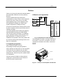
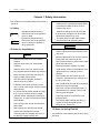
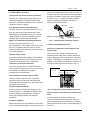
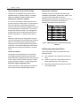
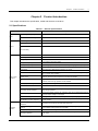
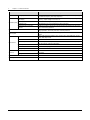
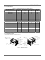
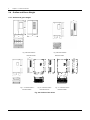
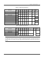
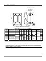
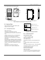
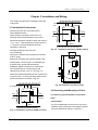
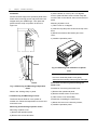
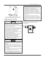
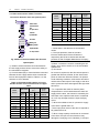
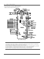
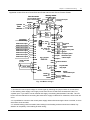
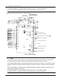
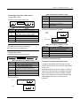
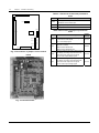
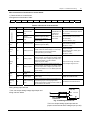
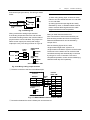
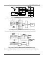
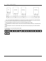
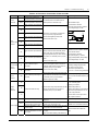
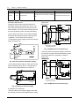
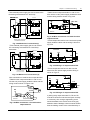
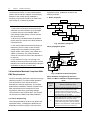
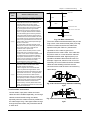
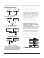
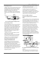
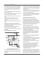

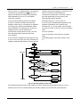
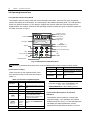
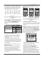
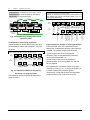
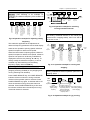
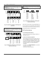
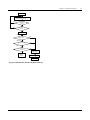
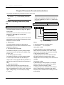
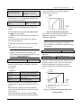
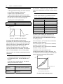
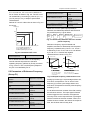
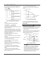
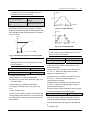
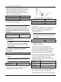
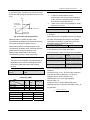
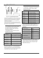
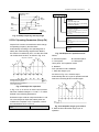
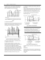
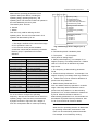
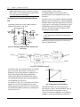
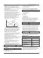
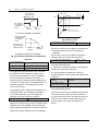
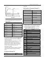
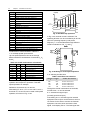
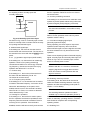
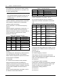
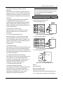
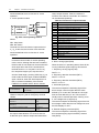
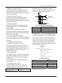
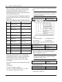
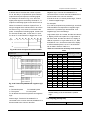
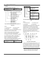
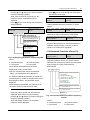
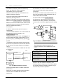
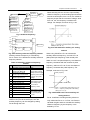
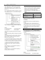
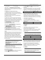
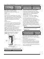

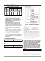
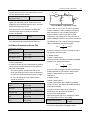
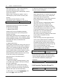
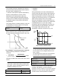
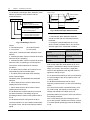
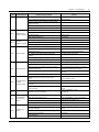
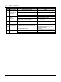
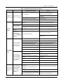
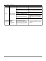
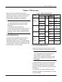
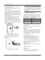
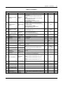
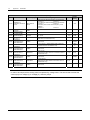
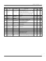
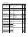

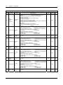
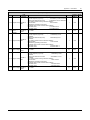
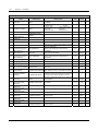
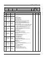
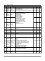
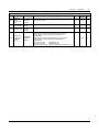
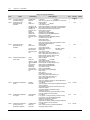
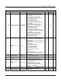
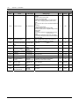
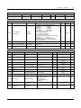
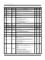
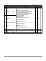
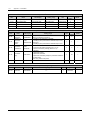
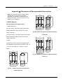
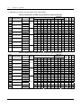
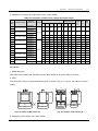
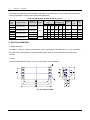
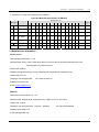
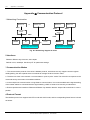
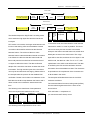
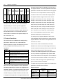
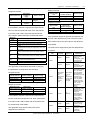
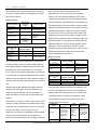
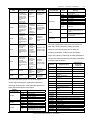
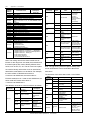
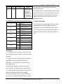
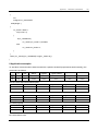
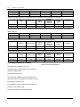
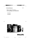
![[AC10] : HA502320U001 : Quickstart Guide to support the Parker](http://vs1.manualzilla.com/store/data/006217721_1-0f90eef9876ce441c4915239f16f04c8-150x150.png)