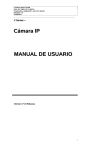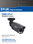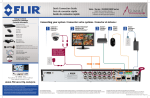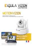
1
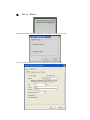
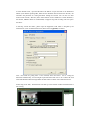
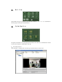
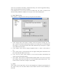
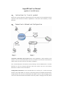
SuperIPCam User Manual
(applied to V seriel IPCamera)
一、
Instructions for V serial product
Please refer to specific manual for detailed instructions. This manual is a brief introduction on the
operation of the customer-end software “SuperIPCam” to watch the video recorded by V series
IPCamera.
二、
Connection to Network and Configuration
Connection of IPCamera and Network: Before using SuperIPCam, connect IPCamera to the
network.. You can connect the IPCamera into LAN,.or connect it into LAN then to the Internet by
ADSL. Please refer to the chart above for Mode 1 and Mode 2.
Note: Connect IPCamera to the Internet strictly according to the two methods above. If connect
IPCamera into the LAN through multi-layer router, then connect the LAN to the Internet,
IPCamera is not able to access to the Internet.
Configuration of IPCamera: If user want IPCamera to be visited by PC 1 and PC 2 thorough
Internet. If user adopts Mode 1 to connect it to the internet, please set the PPOE of the IPCamera.
If adopt Mode 2, user need to set the IPCamera’s IP address in the LAN and do mapping on the
router at the same time. Because the IP address achieved by ADSL is changing all the time, Please
set the DDNS of the IPCamera properly.
Note: For more information, Please refer the specific manual.
三、
The Installation of software SuperIPCam
Double click the SuperIPCam icon, choose installation language, English or Chinese.
Click “OK”, follow instructions to finish the installation.
Run this software, you will see a window as below.
四、
Add an IPCamera
Right-click the mouse in the area showed above, you will see a dialogue box as below.
Choose V serials, click “OK”, you will see the IPCamera setting page as below.
If select IP/URL mode , input the IPCamera’s IP address or input the URL of the IPCamera’s
DDNS. (Note: Before inputting URL, make sure the IPCamera has accessed to the Internet.). Set
username and password for visiting IPCamera through IE browser. You can also set other
functions like “Alarm”, “Record” (Note: Alarm function is not available for V Serial IPCamera.).
For Record, MPEG-4 format is recommended, It supports long time recording and saves space.
See above.
If selecting “Serial NO mode”, please input the Equipment Code which is assigned by the
manufacturer. (Note: for detailed instruction, Please refer to Appendix). See below.
Note: “TCP mode for getting data”. If not Checked, when more than 1 user is visiting the
IPCamera simultaneously, User end might request data from other users so as to reduce the work
load of the IPCamera. But this might make the data stream not stable. Users make their choice.
Finish setup, click “OK”, The IPCamera will show up in the software. Double click IPCamera to
start visiting.
五、
Operation of the active window
Click one of the windows to make it active
Right click within the window, an operation menu will come up. Or click one of the three buttons
at the lower right corner to setup snapshot, alarm, or video record.
Remotely control the Pan/Tilt to move the IPCamera UP, DOWN, RIGHT, LEFT, or make it Auto
Scan. Please refer to the below picture.
For V series IPCamera, the buttons showed below is not available, please ignore it.
The 3 buttons showed above are quick launch to Start, Quit, or Setup.
六、
Multi View
Choose multi view style according to your needs. For example: 1、4、9、15、25、64 frames etc.
Turn the page if viewing too many IPCamera.
七、
System Operation
The picture showed above is System Operation window, click “Start All”, all IPCameras will start
to work, click “Stop All’, all IPCameras will stop.
1. View History Record
Click “Records”, a dialogue box will come up, browse the history record to view.
There are two methods of Recording, “Planned Recording” and “Alarm Triggered Recording”,
Setup to Alarm and Record function accordingly.
In this dialogue box, User can also review the recorded video. The video is recorded in the
standard coding of MPEG4 or MJPEG, User can play it in the normal media players.
2. SuperIPCam Setting
Click “Options”, a dialogue box will come up, setup the User-end software.
In the “Storage” menu, Click “add” or “Delete”, choose save path for recording. Set “save
days”, expired record will be automatically deleted to save storage space. Set “Recording the
file’s length”, it will record block after block within default time span, keep files in a proper
size to make index convenient.
b. In the “Display” menu, choose to display “Equipment Name” or “Time” on the window or
a.
not.
c. In the “Alarm” menu, V series IPCamera does not support sending alarm information to the
port of TCP and UDP 30000 at User’s end.
d. In the “Auto run” menu, choose whether to run the user-end software automatically and
connect all the monitoring IPCameras.
e. In the ‘Others” menu, choose to set DDNS address (Default address: server.nwsvr.com, please
don’t change). In the multi-view mode, User can set automatic page-turning intervals”. User
can also choose “Cache mode” to improve video stability.
3. Others
Click “Other” at lower right corner, User can view Equipment List, manage Log and Operator. In
the “About” menu, User can check software version number and New version availability to
download.
Appendix: Serial Number mode
For V series IPCameras, User can setup DDNS with the code on the white label attached on
IPCamera body(Please refer to the UserManual). Or use another set of Equipment Code got from
manufacturer. the Equipment Code is only available when you selecting “Serial Number mode”.
If user want to set the DDNS with the another Equipment Code got from manufacturer, please
follow the following steps
1. Preparation
Make sure IPCamera successfully connected to the Internet, port was mapped on the router,
IPCamera can be visited from the Internet.
2. Set DNS Server Addresses
Click the “System Configuration”, choose “Network Settings”, Set Preferred DNS server address
and Alternate DNS server address as below.
3. DDNS Setting
a.
Web Service Port is at random, the default port is 81
b. Choose “myddns.com” as DDNS service provider.
c. Log-in name is a mix of Equipment Code provided by the manufacturer and Web server port
of the IPCamera. For example, if the Equipment Code is “001aaaz”, and Web server port is
“81”, the log-in name will be “001aaaz&port=81”.
d. Password is provided by the manufacture attached on the IPCamera body.
e.
DDNS name is the same as the Equipment Code. For example, fill “001aaaz”if the
f.
Equipment Code is “001aaaz”.
Others are not required.
4. Status Checking
After setting, restart the IPCamera. Go to IPCamera setting page, check the status of DDNS in
“System Status”. If the status is the same as below, it means the IPCamera has successfully
registered on the DDNS server.
If the status shows that the DDNS registration failed, check the router, the LAN, port mapping, see
if the IPCamera has access to the Internet. Or restart the IPCamera and check again.
Note: To check if the port mapping is set successfully, input the Public IP address of the Router in
IE Browse. If it can be connected to the IPCamera, then the port mapping was successful. If not,
please check if the configuration of port mapping and the network connection is proper.
After successfully registering a DDNS account, users can visit the IPCamera at URL
http://equipmentcode.nwsvr.com. For example if the Equipment Code is “001aaaz”, the URL will
be http://001aaaz.nwsvr.com..
Note; This URL is a forwarded one, not a real URL