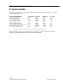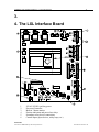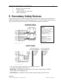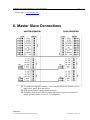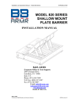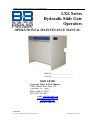
1
Installation and Operations Manual — LXL Gate Operator 1 LXL Series Hydraulic Slide Gate Operators OPERATIONS & MAINTENANCE MANUAL Model No.:_______________________ Serial No.: _______________________ B&B ARMR Corporate Office & Tech Support: 2009 Chenault Drive Suite 114 Carrollton, TX 75006 Phone: (800) 367-0387 Fax: (972) 385-9887 E-mail: [email protected] [email protected] www.bb-armr.com MADE IN THE USA B&B ARMR A Division of B&B Roadway and Security Solutions 0054-9001UL Revision A2 Installation and Operations Manual — LXL Gate Operator 2 Your safety is extremely important to us. If you have any questions or are in doubt about any aspect of the equipment, please contact us. Introduction Welcome! Congratulations on your purchase of a B&B ARMR gate operator. In addition to providing detailed operating instructions, this manual describes how to install, maintain, and troubleshoot your operator. If you require additional assistance with any aspect of installation or operation, please contact us. Safety SYMBOL MEANING: The lightning flash with arrowhead symbol, within an equilateral triangle, is intended to alert the user to the presence of non insulated "dangerous voltage" within the product's enclosure that may be of sufficient magnitude to constitute a risk of electric shock to persons. The exclamation point within an equilateral triangle is intended to alert the user to the presence of important operating and maintenance (servicing) instruction in the literature accompanying the product. B&B ARMR A Division of B&B Roadway and Security Solutions 0054-9001UL Revision A2 Installation and Operations Manual — LXL Gate Operator 3 Important Safety Information TO REDUCE THE RISK OF SERIOUS INJURY OR DEATH, READ AND FOLLOW ALL INSTRUCTIONS PROVIDED IN THIS MANUAL. 1. Hydraulic slide gate operators are intended for vehicular use only. Pedestrians should use a separate walkthrough entrance designed for on-foot traffic. 2. Keep children away from gate movement area and off the gate operator. Never let children operate or play with gate controls. 3. Install all warning signs provided with the gate operator so that they are clearly visible from both sides of the gate. 4. It is the responsibility of the specifier, designer, purchaser, installer and enduser to ensure the gate system is properly configured for its intended application. 5. Use the emergency manual release only when the gate is not in motion. 6. Test gate operator and all related safety devices monthly. The gate must reverse or stop when a safety device is tripped. The gate must stop upon sensing a second sequential safety violation before reaching a limit switch. If the gate utilizes a transmitting device on a safety edge, check the battery on a regular basis to ensure proper operation. Failure to adjust and re-test the gate operator properly can increase the risk of injury. 7. This gate operator utilizes a pumping system which contains hydraulic fluid. Consult local EPA (Environmental Protection Agency) regulations for damming requirements (if any) around the base of the gate operator. 8. Service and maintenance of the gate operator should be performed on a routine basis by a qualified technician. Attempts to service the gate equipment by non-qualified personnel could result in serious injury and will void all applicable warranties. SAVE THESE INSTRUCTIONS. THIS MANUAL SHOULD BE LEFT WITH A RESPONSIBLE INDIVIDUAL AT THE INSTALLATION SITE AND KEPT IN A DESIGNATED LOCATION FOR MAINTENANCE OR TROUBLESHOOTING OPERATIONS B&B ARMR A Division of B&B Roadway and Security Solutions 0054-9001UL Revision A2 Installation and Operations Manual — LXL Gate Operator 4 How to Contact Us If you have any questions or experience any problems with your vehicle barrier—or if we can help you with any other facility security issues—please contact us directly at: Corporate/Tech Support: B&B ARMR 2009 Chenault Drive Suite 114 Carrollton, TX 75006 USA Telephone: (972) 385-7899 Toll Free: (800) 367-0387 Fax: (972) 385-9887 E-mail: [email protected] [email protected] B&B ARMR A Division of B&B Roadway and Security Solutions 0054-9001UL Revision A2 Installation and Operations Manual — LXL Gate Operator 5 Table of Contents Introduction .............................................................................................................................. 2 Safety ......................................................................................................................................... 2 How to Contact Us ................................................................................................................... 4 1. UL 325 And Gate Operators .............................................................................................. 6 1.1 What Is UL? .................................................................................................................................................... 6 1.2 Development Of UL-325 ................................................................................................................................. 6 1.3 Overview Of UL-325 And Gates ..................................................................................................................... 6 1.4 Gate Operator Classifications ........................................................................................................................ 7 2. LXL Operator Models And Features ................................................................................ 9 2.1 General Description ........................................................................................................................................ 9 2.2 LXL Operator Features ................................................................................................................................... 9 2.3 Models Available ........................................................................................................................................... 10 4. The LXL Interface Board................................................................................................. 11 5. Secondary Safety Devices................................................................................................. 12 6. Master Slave Connections ................................................................................................ 13 7. Other Device Connections ............................................................................................... 14 8. Maintenance ..................................................................................................................... 15 1.1 Hardware / Drive Wheels .............................................................................................................................. 15 1.2 Hydraulic System .......................................................................................................................................... 15 1.3 Electronic Components ................................................................................................................................. 15 9. Appendix .......................................................................................................................... 17 1.4 General Parts Breakdown ............................................................................................................................. 18 1.5 Battery Backup Schematic ............................................................................................................................. 20 10. Troubleshooting ...........................................................................................................28 1.6 Alarm Definitions ......................................................................................................................................... 28 1.7 PLC Input/Output Definitions ...................................................................................................................... 28 1.8 Equipment Maintenance Log Form ............................................................................................................... 31 11. Warranty Information ......................................................................................................32 B&B ARMR A Division of B&B Roadway and Security Solutions 0054-9001UL Revision A2 Installation and Operations Manual — LXL Gate Operator 6 1. UL 325 And Gate Operators 1.1 What Is UL? Underwriters Laboratories, Inc., a non-profit organization established in 1894, is selfdescribed as “the leading third-party certification organization in the United States and the largest in North America.” UL’s primary stated mission is “to evaluate products in the interest of public safety.” Note that while UL declares it is the “leading” third-party certification, it is not the only one. There are other testing laboratories and certification organizations in the United States. 1.2 Development Of UL-325 The first edition of UL-325 was released in 1973. That edition was primarily focused on the electric operation of garage doors and did not contain provisions for gates. After federal laws were enacted in the early 1990’s, citing the provisions of UL-325 as applicable to garage door operation, DASMA members of the gate operator industry initiated the inclusion of electric gate operator provisions in UL-325. Some government agencies and other interested groups have monitored the standard’s progress and have provided input on the final format of the provisions of the standard that relate to gate operators. 1.3 Overview Of UL-325 And Gates Highlights of UL-325 include the following: • A glossary which defines each type of operator • Different “classes” of gate operators • Entrapment1 protection criteria for each “class” of operator • Entrapment alarm criteria • Requirements for gate construction and installation • Instructional requirements placing increased responsibility on installers A key part of the UL-325 standard is a table that summarizes the entrapment device options for different classes of operators of the various types of gates included in the standard. The table, labeled “Table 31.1”, is reproduced here from the 5th edition of the Standard for Safety for Door, Drapery, Gate, Louver, and Window Operators and Systems, UL-325. It is reprinted with the permission of Underwriters Laboratories, Inc. Refer to the table as you read about the provisions that are described in the following sections. In this document, “entrapment” is defined as “the condition when an object is caught or held in a position that increases the risk of injury.” 1. B&B ARMR A Division of B&B Roadway and Security Solutions 0054-9001UL Revision A2 Installation and Operations Manual — LXL Gate Operator 7 PROTECTION AGAINST ENTRAPMENT VEHICULAR USAGE CLASS GATE OPERATOR CATEGORY Horizontal Slide SWING GATE VERTICAL LIFT VERTICAL BARRIER (ARM) VERTICAL PIVOT PRIMARY SECONDARY PRIMARY TYPE SECONDARY TYPE TYPE TYPE Class I & II A B1,B2 or D A or C A,B1,B2,C or D Class III A,B1 or B2 A,B1,B2,D or E A,B1,B2 or C A,B1,B2,C,D or E Class IV A,B1,B2 or D A,B1,B2,D or E A,B1,B2,C or D A,B1,B2.C,D or E NOTE: The same type of device shall not be utilized for both the primary and secondary entrapment protection means. Use of a single device to cover both the openings and closing directions is in accordance with this requirement; however, a single device is not required to cover both directions. A combination of one Type B1 for one direction and one Type B2 for the other direction is the equivalent of one device for the purpose of complying with the requirements of either the primary or secondary entrapment protection means. Entrapment protection types: Type A - Inherent entrapment sensing system. See 31.1.5 TypeB1 - Provision for connection of, or supplied with, a non-contact sensor (photoelectric sensor or the equivalent). See 31.1.6-31.1.9. Type B2 - Provision for connection of, or supplied with, a contact sensor (edge device or equivalent). See 31.1.7 and 31.1.10 - 31.1.12. Type C - Inherent adjustable clutch or pressure relief device. See 31.1.13. Type D - Provision for connection of, or supplied with, an actuating device requiring continuous pressure to maintain opening or closing motion of the gate. See 31.1.14 and 31.1.15. Type E - An inherent audio alarm. See 31.1.16, 31.1.17 and 31.1.18. This table is re-created from the 5th edition of the Standard for Safety for door, drapery, gate, louver, and Window Operators and Systems, UL-325, and is reprinted with permission of Underwriters Laboratories, Inc. 1.4 Gate Operator Classifications Four distinct types of classifications have been established: • Class I: Residential usage, covering one to four single-family dwellings. • Class II: Commercial usage where general public access is expected; a common application would be a public parking lot or gated community. • Class III: Industrial usage where limited access is expected; one example is a ware- house property entrance not intended to serve the general public. • Class IV: Restricted access; this includes applications such as a prison entrance that is monitored either in person or via closed circuit television. Gate speed shall be no greater than 1 foot per second in Class I and II applications. B&B ARMR A Division of B&B Roadway and Security Solutions 0054-9001UL Revision A2 Installation and Operations Manual — LXL Gate Operator 8 Figure 1 Non-Contact Sensor Detail Figure 2 Contact Sensor Detail B&B ARMR A Division of B&B Roadway and Security Solutions 0054-9001UL Revision A2 Installation and Operations Manual — LXL Gate Operator 9 2. LXL Operator Models And Features 2.1 General Description B&B ARMR’s model LXL hydraulic sliding gate operator is designed to reliably operate many styles of sliding gates, including overhead track, ground track, and cantilever style gates. Our LXL series of operators are designed to operate in all four UL-325 classes of operators. The operator is unobtrusive in appearance, yet durable under heavy use. The design of the LXL Series incorporates numerous features intended to improve safety, maintain security, increase reliability and reduce maintenance. The operator actuates the gate by two rotating wheels (the LXLR uses an idler wheel and pinion gear). A drive rail bolted to the gate is drawn between the two drive wheels. The wheels are spring loaded against the drive rail to produce a positive friction feed in both directions. Spring loading the wheels also serves to correct for wheel wear. The drive wheels are rotated by seriesconnected hydraulic motors to minimize uneven rotation between the wheels. Rotation direction is determined by the hydraulic valve system, not by the rotational direction of the electric motor. Independence from the electric motor rotation has the advantage that the direction of gate travel can be instantly reversed without the use of brakes. Also, the hydraulic valve, when not energized, rests in the neutral position. This effectively locks the hydraulic system, drive wheels, and the gate in the stopped position. Controls operate on safe and reliable 24VDC regulated voltage. 2.2 LXL Operator Features The LXL hydraulic slide gate operator incorporates the following features and options: • Designed to meet UL-325 Class I-IV. • Inherent entrapment sensing on all units • Simple user interface utilizes a 12x4 character LCD display • User-Programmable right-hand to left-hand conversion; no hose swapping required • Delay on reverse standard • 24VAC and 24VDC auxiliary control power • Low maintenance - No sprockets, chains, or pulleys to adjust • Built-in, fully adjustable maximum run and auto close timers • Soft start / soft stop (option) • Plug-in loop detectors (option) • Hand-operated, quick release drive system for manual operation • Master/slave capability • Interlocking capability • Proximity limit switches eliminate false tripping due to misaligned drive rail B&B ARMR A Division of B&B Roadway and Security Solutions 0054-9001UL Revision A2 Installation and Operations Manual — LXL Gate Operator 10 2.3 Models Available NOTE: To order any of the LXL models, substitute the required input voltage for the "v" and the required input phase for "p". Typical Available Models Travel Speed Gate Size Pull Force UL Class LXL-15vp-SS Standard Speed LXL-15vp-HS High Speed LXL-20vp-HD Heavy Duty LXLR-15vp-SS Rack & Pinion LXLR-20vp-HD Rack & Pinion LXLB-13vp-SS Battery Back-up LXLB-13vp-HS Battery Back-up High Speed LXLD-20vp-SS Extra Heavy Duty LXLT-30vp-SS Extreme Heavy Duty 1.0 ft/s 2.0 ft/s 1.0 ft/s 1.0 ft/s 1.0 ft/s 1.0 ft/s 1.0 ft/s 0.8 ft/s 0.8ft/s 400 lbs 300 lbs 600 lbs 350 lbs 450 lbs 350 lbs 350 lbs 1,700 lbs 1,800 lbs I-IV III & IV I-IV I-IV I-IV I-IV III & IV I-IV III-IV 2,000 lbs 1,000 lbs 3,000 lbs 3,000 lbs 4,700 lbs 2,000 lbs 1,000 lbs 20,000 lbs 25,000 lbs a. Travel speed on all operators limited to 1 foot per second in Class I and II applications. Other models for extra heavy-duty operation are available for extremely long and heavy gates. Contact your local distributor or the factory for more information. B&B ARMR A Division of B&B Roadway and Security Solutions 0054-9001UL Revision A2 Installation and Operations Manual — LXL Gate Operator 11 3. 4. The LXL Interface Board ESC 1 2 3 4 5 6 OK 24VAC/24VDC auxiliary power Processor/Controller Built-in 3 button station Position indication and power loss relays Secondary safety device connections Control inputs (open devices, safety loops, etc.) B&B ARMR A Division of B&B Roadway and Security Solutions 0054-9001UL Revision A2 Installation and Operations Manual — LXL Gate Operator 7 8 9 10 12 Input power for control board Contactor output 1 amp fuse (processor protection) Factory connections 5. Secondary Safety Devices Connecting safety devices to the secondary safety connectors will stop the gate on the detection of the safety and proceed in the event of clearing the safety. To reverse the gate on the event of a safety, you must connect the safety device to the loopsafe terminal on connector 3. IMPORTANT NOTE: UL 325 approved secondary safety devices MUST be used for the gate installation to comply with the requirements of UL 325. Refer to the UL approved manufacturer’s documentation for proper installation of secondary safety devices. *Note: The ROAD and BACK connections are normally open connections UL Approved Secondary Safety Devices: Miller Edge - manufacturer of contact sensors for all types of gates (800-220-EDGE). website: http://www.milleredge.com EMX Industries - manufacturer of non-contact sensors for gates (800-426-9912). B&B ARMR A Division of B&B Roadway and Security Solutions 0054-9001UL Revision A2 Installation and Operations Manual — LXL Gate Operator 13 website: http:// www.emxinc.com 6. Master Slave Connections 10 conductors required for master / slave connection between operators (16-18 gauge wire), plus 4 for safety devices Each operator must be programmed separately Secondary safety devices must be connected to their respective operators for proper operation, and to ensure UL 325 compliance B&B ARMR A Division of B&B Roadway and Security Solutions 0054-9001UL Revision A2 Installation and Operations Manual — LXL Gate Operator 14 7. Other Device Connections B&B ARMR A Division of B&B Roadway and Security Solutions 0054-9001UL Revision A2 Installation and Operations Manual — LXL Gate Operator 15 8. Maintenance Here is a list of items that should be checked on a routine basis. 1.1 Hardware / Drive Wheels Check for normal wheel wear - Look for cracks or pieces of the wheel tread that may have worn or broken off. The drive wheels require periodic replacement under normal service when the wheels become out-of-round or have cracked. Over tightening of the wheel clamping spring will shorten the wheel life. Check for loose or broken fasteners - This check should also include the fasteners on the gate panel. A broken fastener on the gate panel could cause undue stress on the operator. Also, inspect the anchor bolts that hold the gate operator in position. While inspecting these bolts, check for signs the operator has “walked” out of its original mounting position Cycle test the operator - Run the gate through several cycles to confirm that there is no binding of the gate panel and that the drive rail is properly aligned with the gate operator. Also, monitor the wheels for slippage. If the wheels slip, tighten down on the spring adjustment nut until no slippage occurs during normal gate travel. Tighten the spring only enough to eliminate slippage during normal travel. 1.2 Hydraulic System Remove the vent cap and check the hydraulic fluid level -The vent cap is located on the reservoir assembly (bottom right of the operator). After removing the vent plug, a visual inspection should show the fluid level no more than 1” below the vent plug. If fluid needs to be added, use Envirologic EL132 hydraulic fluid. Other available hydraulic fluids are: Texaco Aircraft Oil #15 Mobil DTE 24 IMPORTANT NOTE: All B&B ARMR operators ship with Envirologic EL132 hydraulic fluid. If another hydraulic fluid is substituted; the existing fluid must be drained to avoid mixing. Never mix hydraulic fluids! Check for leaks in the hydraulic system - This includes the hydraulic lines, reservoir and fittings. Leakage may occur in the fittings after a period use. If this happens, moderate tightening of the hose fittings should stop the leakage. If the leak persists, replace the leaking hose assembly. 1.3 Electronic Components Check for loose or frayed wires - Carefully inspect all input and output connections to ensure all wires are seated properly in the terminal blocks. A loose or frayed wire can create different “phantom” problems. B&B ARMR A Division of B&B Roadway and Security Solutions 0054-9001UL Revision A2 Installation and Operations Manual — LXL Gate Operator 16 Check gate input devices for proper operation - These devices include push buttons, keypads, loops, etc. An improperly functioning input device could give the impression the gate operator is malfunctioning. Test all safety devices for proper operation - Test the inherent safety to ensure the gate reverses after coming in contact with an obstruction. Adjust the hydraulic pressure by following step 12 in the Installation and Programming section of this manual. B&B ARMR A Division of B&B Roadway and Security Solutions 0054-9001UL Revision A2 Installation and Operations Manual — LXL Gate Operator 17 9. Appendix ** Note: There are some changes in the drawing below. Standard speed setup is shown. For high speed and rack and pinion users please note that these item numbers are different: Number 31 will be XHYD-103-1572 for standard and high speed units Number 31 will be 0050-RS-1001010 for rack and pinion units Number 9 will be XHYD-M406-0103 for high speed units *Also, note for electrical components such as transformers or motors your voltage and phase may change the part number required . LXL electrical cubical B&B ARMR A Division of B&B Roadway and Security Solutions 0054-9001UL Revision A2 Installation and Operations Manual — LXL Gate Operator 18 1.4 General Parts Breakdown Typical Installation B&B ARMR A Division of B&B Roadway and Security Solutions 0054-9001UL Revision A2 Installation and Operations Manual — LXL Gate Operator B&B ARMR A Division of B&B Roadway and Security Solutions 19 0054-9001UL Revision A2 Installation and Operations Manual — LXL Gate Operator 20 1.5 Battery Backup Schematic B&B ARMR A Division of B&B Roadway and Security Solutions 0054-9001UL Revision A2 Installation and Operations Manual — LXL Gate Operator 21 Battery backup Parts List ITEM QTY B&B ARMR # B&B ARMR A Division of B&B Roadway and Security Solutions DESCRIPTION 0054-9001UL Revision A2 Installation and Operations Manual — LXL Gate Operator B&B ARMR A Division of B&B Roadway and Security Solutions 22 0054-9001UL Revision A2 Installation and Operations Manual — LXL Gate Operator B&B ARMR A Division of B&B Roadway and Security Solutions 23 0054-9001UL Revision A2 Installation and Operations Manual — LXL Gate Operator B&B ARMR A Division of B&B Roadway and Security Solutions 24 0054-9001UL Revision A2 Installation and Operations Manual — LXL Gate Operator B&B ARMR A Division of B&B Roadway and Security Solutions 25 0054-9001UL Revision A2 RUN/STOP 26 B&B ARMR A Division of B&B Roadway and Security Solutions 12/24 RC LOGO! SIEMENS ESC OK DM8 12/24R Installation and Operations Manual — LXL Gate Operator 0054-9001UL Revision A2 RUN/STOP 6ED1 055-1MB00-0BA1 27 B&B ARMR A Division of B&B Roadway and Security Solutions 6ED1 055-1MB00-0BA1 12/24 RC LOGO! SIEMENS ESC OK RUN/STOP DM8 12/24R LOGO! SIEMENS 12/24 RC ESC OK DM8 12/24R Installation and Operations Manual — LXL Gate Operator 0054-9001UL Revision A2 Installation and Operations Manual — LXL Gate Operator 28 10. Troubleshooting The table below provides a general guidance on identifying and correcting any problems with your LXL Series gate operator. If you encounter problems that you cannot fix, contact B&B ARMR and we will gladly work with you to correct them. 1.6 Alarm Definitions – Continuous solid beep – Gate is moving or a Stop command is active 5sec On, 1sec Off – MaxRun Time Error 1sec On, 1sec Off – Forward and/or Reverse Safety 0.25sec On, 0.5sec Off – Inherent Safety Error 1.7 PLC Input/Output Definitions – B&B ARMR A Division of B&B Roadway and Security Solutions 0054-9001UL Revision A2 Installation and Operations Manual — LXL Gate Operator Symptom Gate operator does not respond when commanded. Gate operator drives the gate in the incorrect direction. Operator drives gate too slowly. MAX Runtime Error Date and time flash on the PLC. Gate does not stop automatically when encountering an obstacle. Operator drive wheels slip on gate and gate does not move. Fuses are blowing. PLC says Stop/Reset activated. 29 Actions 1. Check CONN 9 for power when command is given. 2. Check overload protector 3. Check PLC output. 4. Check that safeties are clear, and that IR Beams are aligned. 5. Check PLC input. 6. Check the +24VDC at CONN3 pins 8 and 10 1. Refer to step 4.10 of Installing and Programming the LXL Operator for setting the handing. 2. Refer to step 4.5 of Installing and Programming the LXL Operator to check for correct installation of the Limit Switch Plates. 1. Check for any binding of the gate. 2. Check for slippage of the drive wheels. 3. Check the fluid level in the reservoir. 4. Check the quality of the hydraulic fluid. Old fluid will become sludgy and clogging of internal filter is possible. 1. Check for any binding of the gate. 2. Check for slippage of the drive wheels. 3. Check the fluid level in the reservoir. 4. Check the MAX RUN TIME setting in Parameters to insure sufficient time is set for the gate size. 5. REMEMBER – Gate only may only move 1 ft/sec 1. Refer to step 4.11 of Installing and Programming the LXL Operator for setting the date and time. (Optional, not required to be set) 1. Refer to step 4.15 of Installing and Programming the LXL Operator for setting the Inherent Safety. 2. Check for system pressure on Inherent Safety screen of the PLC, if no reading is evident while gate is running suspect a faulty pressure transducer. 3. Check the functionality of the safety devices. 4. Check safety device wiring, refer to sections 6 and/or 8 1. Check for binding by disengaging the drive wheels, and ensuring that the gate rides smoothly manually. 2. Check the tension of the drive wheels, adjust as needed. 3. Check for any water or precipitation on the drive rail. 1. Check for incorrect incoming power to the LXL board. 2. Ensure all external devices are sending the correct voltage to the LXL board, and that there are no shorts. 1. If using an external push button, ensure that the stop button is a normally closed contact. 2. If not using an external push button, ensure there is a jumper wire between stop/reset and +24 stp/rst on CONN 3. 3. Check the connection of the wire between the J1Pin 9 B&B ARMR A Division of B&B Roadway and Security Solutions 0054-9001UL Revision A2 Installation and Operations Manual — LXL Gate Operator Symptom Electric Motor turns but gate does not move. 30 Actions connector and I7 of the PLC. 4. Verify shunt is present on JP1 between pins 1 and 2. 5. Check F3. 1. Check the fluid level in the reservoir. 2. Check PLC outputs to see if Q1 turns on for an OPEN and/or Q2 turns on for a CLOSE. 3. Disengage drive wheels and check to see if they move. 4. If drive wheels move, check for binding in the gate. 5. If drive wheels do not move, check for loose coupling between the electric motor and pump assembly. 6. Check for voltage between COM and HYD VAL 1 and 2 on CONN 1 of LXL board, and ensure wires connections are tight. 7. If voltage is correct, manually shift the detent in the center of the solenoid on either side of the hydraulic valve, if wheels move suspect hydraulic valve. 8. If wheels do not move after manually shifting the detent, suspect pump assembly. 9. If unit is a 3 phase unit and a new installation, reverse two of the incoming power leads. B&B ARMR A Division of B&B Roadway and Security Solutions 0054-9001UL Revision A2 Installation and Operations Manual — LXL Gate Operator 31 1.8 Equipment Maintenance Log Form Product Type: ____________________ Location: ________________________ Jan Checklist Complete Yes No Feb Yes No Mar Yes No Apr Yes No May Yes No Jun Yes No Jul Yes No Aug Yes No Sep Yes No Oct Yes No Nov Yes No Year Yes No Date Date Performed By Performed By Checklist Complete Jan Yes No Feb Yes No Mar Yes No Apr Yes No May Yes No Jun Yes No Jul Yes No Aug Yes No Sep Yes No Oct Yes No Nov Yes No Year Yes No B&B ARMR A Division of B&B Roadway and Security Solutions Anomalies Notes Anomalies Notes 0054-9001UL Revision A2 Installation and Operations Manual — LXL Gate Operator 32 11. Warranty Information BBRSS warranties for a period of one (1) year FOB manufacturing facility, unless otherwise specified by BBRSS in writing, from defects due to faulty material or workmanship. Damage due to handling during shipment and installation are not covered under warranty. BBRSS assumes no responsibility for service at customer site. BBRSS is in no event responsible for any labor costs under the warranty. Subject to the above limitation, all service, parts, and replacements necessary to maintain the equipment as warranted shall be furnished by others. BBRSS shall not have any liability under these specifications, other than for repair or replacement as described above for faulty product material or workmanship. Equipment malfunction or equipment failure of any kind, caused for any reason, including, but not limited to unauthorized repairs, improper installation, installation not performed by BBRSS authorized personnel, incoming supply power is outside the tolerance for the product, failure to perform manufacturer’s suggested preventative maintenance, modifications, misuse, accident, catastrophe, neglect, natural disaster, are not under warranty. The exclusive remedy for breach of any warranty by BBRSS shall be the repair or replacement at BBRSS’s option, of any defects in the equipment. IN NO EVENT SHALL BBRSS BE LIABLE FOR CONSEQUENTIAL OR SPECIAL DAMAGES OR ANY KIND OF PERSONAL DAMAGES. Except as provided herein, BBRSS makes no warranties or representations to consumer or to anyone else and consumer hereby waives all liability against BBRSS as well as any other person for the design, manufacture, sale, installation, and/or servicing of the Products. THE FOREGOING WARRANTIES ARE IN LIEU OF ALL OTHER WARRANTIES EXPRESS OR IMPLIED, INCLUDING THE IMPLIED WARRANTY OF MERCHANTABILITY AND FITNESS FOR A PARTICULAR PURPOSE. NO OTHER WARRANTIES EXIST. Any modification or alteration by anyone other than BBRSS will render the warranty herein as null and void. B&B ARMR A Division of B&B Roadway and Security Solutions 0054-9001UL Revision A2