1
KD-RDU-420
Page 1 / 22
KD-Relay Remote Display
4x20 Display
User Manual
KD-RDU-420
Version 00.02
(NE_KD-RDU-420_MAN_00_11_FN02)
01 February 2011
NewElec Pretoria (Pty) Ltd
Head Office: c/o 298 Soutter street & Maltzan street
Pretoria West
South-Africa
0182
GPS: 25°45'12''S 28°09'46''E
Http://www.newelec.co.za
KD-RDU-420
Page 2 / 22
Content
Page
1. ABSTRACT......................................................................................................................................3
2. SPECIFICATIONS..........................................................................................................................4
2.1 Technical Specifications of RDU.................................................................................................4
2.4 Menu Structure with Unit Ranges of MMI...................................................................................5
2.4.1 Main Menu (primary menu - 1st level).................................................................................5
2.4.2 Actual Values (2nd level)......................................................................................................5
2.4.3 Relay Settings (2nd level).....................................................................................................5
2.4.4 Faults – (2nd level)..............................................................................................................5
2.4.5 Events – (2nd level)..............................................................................................................6
2.4.6 RDU Settings (2nd level)......................................................................................................6
2.4.7 Relay Data Time - (2nd level)..............................................................................................6
2.4.8 Relay Info (2nd level)...........................................................................................................6
2.4.9 Settings (3rd level)................................................................................................................7
2.4.10 Input Pointers .....................................................................................................................8
3. DEFINITIONS AND TERMINOLOGY.........................................................................................9
4. FUNCTIONAL DESCRIPTION...................................................................................................10
5. OPERATING INSTRUCTIONS...................................................................................................11
5.1 Getting Started............................................................................................................................11
5.1.1 Installing KD-RDU-420......................................................................................................11
5.2 Navigating Through The Menus.................................................................................................11
5.3 Monitoring Actual Data..............................................................................................................11
5.4 Change or Viewing Settings.......................................................................................................11
5.4.1 Change in RDU memory slots ............................................................................................12
5.4.2 Copy RDU memory slot to RDU memory slot....................................................................12
5.4.3 Upload relay settings to RDU memory slot.........................................................................12
5.4.4 Download MMI memory slot to relay.................................................................................12
5.5 Retrieve and Uploading Event / Fault Records...........................................................................12
5.6 Trouble Shooting (Frequently Asked Questions)........................................................................13
6. DIAGRAMS....................................................................................................................................14
6.1 Physical Layout of the RDU ......................................................................................................14
6.2 Layout Of RDU Front Panel.......................................................................................................15
6.3 Layout Of RDU Back Panel.......................................................................................................16
6.4 Block Diagram of RDU Display Unit.........................................................................................17
6.5 Menu Layout..............................................................................................................................18
6.6 Mechanical Installation Drawing................................................................................................19
6.7 Wiring Diagram..........................................................................................................................20
6.8 Mechanical Drawing..................................................................................................................21
7. ACCESSORIES..............................................................................................................................22
7.1 RDU To Relay Communication Cable.......................................................................................22
7.2 NewElec RDU Dongle Key........................................................................................................22
KD-RDU-420
Page 3 / 22
1. ABSTRACT
The KD-RDU-420 (KD-Relay Remote Display Unit 4x20 Character Display) is a door
mounted display unit, designed to function together with the KD or KE motor protection
relays. It is advisable to read this manual in conjunction with KD or KE user manual.
The purpose of this unit is to provide a front-end facility (man machine interface) between the
operator and the motor protection relay. It is capable to monitor and adjust the motor
protection relay data (if a dongle key is plugged in). The relay data consists of settings, faults,
events and actual data. Settings can be adjusted as a batch or individually. Communication
between the motor protection relay and the display unit (RDU) is done with a communication
cable (CAB0100). IrDA lens can be found on the front control panel of the display unit,
which the KD-MMI-420-EP or KD to PC cable can use to communicate to the KE or KD
relay without opening up the MCC door.
KD-RDU-420
Page 4 / 22
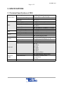
2. SPECIFICATIONS
2.1 Technical Specifications of RDU
Mounting Positions
General Data
RDU
IrDA
RS232
Allowed Ambient Temperature
Humidity
Power Supply
Consumption
Communication Mediums
Physical Dimensions
Mass Of Unit
Communication Distance
Board Rate
Communication Distance
Board Rate
Type
Display
Character Size
Type
Keys
Keyboard
Indication
Lights
CAB0101
Type
LED Indications
Length
●
●
●
●
●
●
●
●
●
●
●
●
●
●
●
●
●
●
●
●
●
●
●
●
●
●
●
●
●
●
Door Mounted
132 mm x 71 mm Cut Out
Operation : 0 ºC to +60 ºC
< 87%
110 to 220 Vac @ 50/60Hz
75 mA
IrDA
RS232
145.84mm X 86.00mm X 70.92mm
375 gram
1 Meter
19200 bits per second
25 Meters
19200 bits per second
4 lines by 20 Characters.
Liquid Crystal Display (LCD).
5mm X 4 mm
Diaphragm
Up
Down
Left
Right
Down
Enter
Reset or Menu
Light Emitting Diode (LED)
Relay Communication
In Service
Trip
2 meters
KD-RDU-420
Page 5 / 22
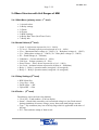
2.4 Menu Structure with Unit Ranges of MMI
2.4.1 Main Menu (primary menu - 1st level)
•
•
•
•
•
•
•
1>Actual values
2>Relay settings
3>Faults
4>Events
5>RDU Settings
6>Relay Date Time (Real Time Clock)
7>Relay Info
2.4.2 Actual Values (2nd level)
•
•
•
•
•
•
•
•
•
•
•
Load – Load current expressed in % (0 – 999%)
TC level – Thermal capacity used expressed in % (0 – 100%)
Vlev – Maximum Phase voltage (0 - 1200V), Vr – Red phase voltage (0 - 1200V)
Vw – White phase voltage (0 – 1200V), Vb – Blue phase voltage (0 – 1200V)
EL – Earth leakage (0 – 3000mA)
Unbalance – Current unbalance (0 – 100%)
Volt Sym – Voltage symmetry (0 – 50%)
Power Factor – Power factor expressed as a % (0 – 100%)
Iso. Lock – Isolation lockout expressed in k Ohm (0 – 200kOhm)
Relay 1 – Relay 1 operation status (energized / de-energized)
Relay 2 - Relay 2 operation status (energized / de-energized)
2.4.3 Relay Settings (2nd level)
•
•
•
•
RDU Mem Slot
Copy Slot → Slot
DwnLd Slot → KX
Upload KX → Slot
2.4.4 Faults – (2nd level)
Fault history retrieved from relay database
• View [Nr] – Fault number x of 60 on display
• Status – Actual fault (caused by real current and voltage) or sim. Fault caused
during simulation of current, voltage, power factor and earth leakage current)
• Type – Trip condition (Any one of the trip flags which is applicable at the time of
the trip)
• DT – Date and time stamp of fault record.
KD-RDU-420
Page 6 / 22
•
•
•
•
Run hour – Motor running hours at the time of the trip expressed in hours.
Current – Max current in % at the time the trip took place (0 – 999%).
Voltage – Minimum phase voltage at the time of the trip (0 – 1200V)
Contact R.T. - Contact release time or time to clear fault expressed in ms. (0 –
1000ms)
2.4.5 Events – (2nd level)
Event history retrieved from relay database
• View [Nr] - Event number x of 2000 on display
• Status – Event type (alarm, trip or setting adjustment)
• DT – Date and time stamp of the event record.
• Alarm Flags – Alarm condition at the time of the recording of the event.
• Trip – Trip condition at the time of the event recording.
• Run hour – Motor running hours at the time of the recording of the event.
• Current – Maximum current at the time the event was recorded.
• Voltage – Minimum phase voltage at the time of the event recording.
• Contact R.T. - Contact release time or time to clear fault expressed in ms. (0 1000ms)
2.4.6 RDU Settings (2nd level)
System settings only for the RDU (not applicable for the relay)
• Auto scroll – Auto scroll the actual values after 5 minutes of no key activity
(Enabled / Disabled).
• Back light auto on – Back light will be turned off after 5 minutes (Enabled /
Disabled).
• Contrast – Contrast adjustment of the LCD images (0 - 100%).
• Brightness – Brightness adjustment of the LCD back light (0 – 100%).
2.4.7 Relay Data Time - (2nd level)
• Date – Relay date adjustment of the real time clock of the relay.
• Time – Relay time adjustment of the real time clock of the relay.
2.4.8 Relay Info (2nd level)
Statistical and user data to manage the drive:
• Start-up counter – Increment every when the motor starts up (0 - 65535).
• Trip counter – Increment every time when a trip occurs (0 – 65535).
• Running hours – Increment every hour the of motor operation (0 – 65535).
• Drive description – Description of drive (20 characters).
• Drive file ID – Unique file name associated with the drive.
KD-RDU-420
Page 7 / 22
2.4.9 Settings (3rd level)
•
•
•
•
•
•
•
•
•
•
•
•
•
•
•
•
•
•
•
•
•
•
•
•
•
•
•
•
•
•
•
•
•
•
•
•
•
•
•
•
•
•
TC Class Select – Thermal Curve Class (5 – 40sec)
Maximum Load Set – Motor full load setting (10% - 100%)
Voltage Select – Supply line voltage level (110V, 400V, 525V or 1050V)
V Sym Trip Level – Voltage symmetry trip level (50% - 100%).
Unbal Trip Level – Current unbalance trip level (0% - 50%)
Unbal Trip Delay – Current unbalance trip delay (1 – 10 sec)
U/C Trip Level – Undercurrent trip level (10 – 99%)
U/C Restart Delay – Undercurrent restart delay (Manual, 10s, …, 1 h, 3h, 6h)
U/C Trip Delay – Undercurrent trip delay (1 – 10 sec)
EL Trip Level – Earth leakage trip level (0 – 3000 mA)
EL Trip Delay – Earth leakage trip delay (100ms – 1sec, in steps of 50ms, IDT)
EL Curve Select – Earth leakage curve select (Instantaneous Definite Time /
Inverse Definite Minimum Time)
Starts per hour – Starts per hour allowed (0 – 30);
U/C Startup Delay – Undercurrent start-up delay, pump priming time (0 – 200s)
Power Fact Level – Power factor trip level setting (0 – 100%)
TC Reset Level – Thermal capacity reset level (10 – 100%, default = 70%)
Consec Start Lim – Consecutive starts limit (1 – 3)
Run Stall T Level – Run-stall Trip Level (110% - 300%)
Run Stall H Time – Run-stall hold off time (1 – 200s)
U/C Trip – Undercurrent trip (Enable / Disable)
Under Volt Trip (Enable / Disable)
Over volt Trip (Enable / Disable)
Volt Symt Trip – Voltage symmetry trip (Enable / Disable)
Fail Safe – (Enable / Disable)
Auto TC Reset – (Enable / Disable)
Unbalance Trip – Current unbalance trip (Enable / Disable)
Phase Rot Trip – Voltage phase rotation trip (Enable / Disable)
Short Circ Trip – Short circuit Trip (Enable / Disable)
Single phase trip – (Enable / Disable)
Running Stall T – Run-stall trip (Enable / Disable)
Sel. U/C for Trip - Undercurrent / Power factor selected for trip (Enable / Disable)
Earth leakage Trip – Earth Leakage Trip (Enable / Disable)
Low Pass Filter – (Enable / Disable)
Iso. Lockout T – Isolation lockout trip (Enable / Disable)
Frequency Trip – Frequency monitoring (Enable / Disable)
Auto TC Reset Cal – (Enable / Disable)
Starts Per Hour – (Enable / Disable)
Volt Phase Rev – (Enable / Disable)
Vectorial Stall T – Vectorial stall trip (Enable / Disable)
Table 1 Mask 0&1 – 000:X, 001:X (X=0/1)
Table 1 Mask 2&3 – 010:X, 011:X (X=0/1)
Table 1 Mask 4&5 – 100:X, 101:X (X=0/1)
KD-RDU-420
Page 8 / 22
•
•
•
•
•
•
•
•
•
•
•
•
•
•
•
•
•
•
•
•
•
•
•
•
•
•
•
Table 1 Mask 6&7 – 110:X, 111:X (X=0/1)
Table 1 Input A – (Input pointer – see 2.4.10)
Table 1 Input B – (Input pointer – see 2.4.10)
Table 1 Input C – (Input pointer – see 2.4.10)
Table 2 Mask 0&1 – 000:X, 001:X (X=0/1)
Table 2 Mask 2&3 – 010:X, 011:X (X=0/1)
Table 2 Mask 4&5 – 100:X, 101:X (X=0/1)
Table 2 Mask 6&7 – 110:X, 111:X (X=0/1)
Table 2 Input A – (Input pointer – see 2.4.10)
Table 2 Input B – (Input pointer – see 2.4.10)
Table 2 Input C – (Input pointer – see 2.4.10)
Table 3 Mask 0&1 – 000:X, 001:X (X=0/1)
Table 3 Mask 2&3 – 010:X, 011:X (X=0/1)
Table 3 Mask 4&5 – 100:X, 101:X (X=0/1)
Table 3 Mask 6&7 – 110:X, 111:X (X=0/1)
Table 3 Input A – (Input pointer – see 2.4.10)
Table 3 Input B – (Input pointer – see 2.4.10)
Table 3 Input C – (Input pointer – see 2.4.10)
Timer A Time Out – (0 – 3000s)
Timer A Start In – (Input pointer – see 2.4.10)
Timer A Reset In – (Input pointer – see 2.4.10)
Timer B Time Out – (0 – 3000s)
Timer B Start In – (Input pointer – see 2.4.10)
Timer B Reset In – (Input pointer – see 2.4.10)
Start Motor – (hh:mm)
Stop Motor – (hh:mm)
Relay 2 Input Sig - (Input pointer – see 2.4.10)
2.4.10 Input Pointers
It is signals that can be routed to the inputs of the logic functions, timers and relay 2.
Zero ('0')
One ('1')
InService
VoltPresentF
OverCrnt_af
ShortCirc_af
RunStall_af
I_Unbal_af
SinglePhase_af
EarthFault_af
EarthLeak_af
MinLoad_af
OverVolt_af
UnderVolt_af
VoltSym_af
HiFreq_af
LoFreq_af
IsoLockOut_af
OverCrnt_tf
ShortCirc_tf
RunStall_tf
I_Unbal_tf
SinglePhase_tf
EarthFault_tf
EarthLeak_tf
MinLoad_tf
OverVolt_tf
UnderVolt_tf
VoltSym_tf
HiFreq_tf
LoFreq_tf
IsoLockOut_tf
PhaseRot_tf
StartsPerHr_tf
Timer_A
! Timer_A
Timer_B
! Timer_B
RTClock
! RTClock
LogicFunc_1
! LogicFunc_1
LogicFunc_2
! LogicFunc_2
LogicFunc_3
! LogicFunc_3
Restart
FrozenContact
KD-RDU-420
Page 9 / 22
3. DEFINITIONS AND TERMINOLOGY
EEPROM
Electrical Erasable Programmable Read Only Memory (non volatile)
Flash memory
Similar to EEPROM (only block write - non volatile)
Galvanic isolation It is the principle of isolating functional sections of electrical system so
that charge-carrying particles cannot move from one section to another,
i.e. there is no electrical current flowing directly from one section to the
next. Energy and/or information can still be exchanged between the
sections by other means, however, such as by capacitance, inductance,
electromagnetic waves, optical, acoustic, or mechanical means.
In service
When the current rise above 10% of full load current it is assumed that
the motor is running.
Intrinsic safe
It is a protection technique for safe operation of electronic equipment in
explosive atmospheres. The concept was developed for safe operation of
process control instrumentation in hazardous areas. The theory behind
intrinsic safety is to ensure that the available electrical and thermal
energy in the system is always low enough that ignition of the hazardous
atmosphere cannot occur.
IrDA
Infrared serial data transmission link.
LED
Light emitting diode (It is used as visual indicators)
RDU
Remote Display Unit – It is a tool to monitor actual values, fault and
event records. It is also used to adjust the relay settings. In retrospect, it
is a more robust alternative, although not as comprehensive, for a laptop
computer with relay front-end software.
MMI
Man Machine Interface – It is a tool to monitor actual values, fault and
event records. It is also used to adjust the relay settings. In retrospect, it
is a more robust alternative, although not as comprehensive, for a laptop
computer with relay front-end software. MMI also refers to the KDMMI-420-EP in this documentation.
Motor protection
relay
It is an intelligent (computerized) unit monitoring an electric motor's
current and voltage supply. In case of overloading, phase lost etc. the
power supply of the motor will be interrupted by the protection relay to
prevent damage to the motor.
Slot
Memory space allocated to keep settings data for relay configuring
purposes.
Dongle key
A custom NewElec key that is used to lock or unlock setting memory
slots in the RDU and settings in the relay.
KD-RDU-420
Page 10 / 22
4. FUNCTIONAL DESCRIPTION
The KD-RDU-420 can be broken down into the following function blocks:
• Micro-Controller
• Keyboard
• IrDA Serial Port
• RS232 Serial Port
• Dongle Port
• Liquid Crystal Display (LCD)
Micro-Controller – Is the core of the system. The micro-controller ensures that the operation
of the KD-RDU-420 gets executed. The micro-controller also saves settings to EEPROM so
that settings can be retrieved after a power loss.
Keyboard – Consist of six keys. The keys allow the operator to give commands to the microcontroller. Four keys are used for scrolling through the menus. The ‘ENTER’ key is used to
select or confirm a command. The ‘MENU or RESET’ key is used to cancel a command or to
reset the relay from a trip condition.
IrDA Serial Port – Is a serial wireless communication interface between the RDU and the
MMI or PC to IrDA. This will allow the operator to connect to the relay via the RDU without
opening the door of the MCC cubical/bucket.
RS232 Serial Port – Is a serial communication interface between the relay and RDU. This will
allow the operator to view faults, events and setting or change settings, while the door of the
MCC cubical/bucket remains closed.
Dongle Port – A dongle key gets inserted into the dongle port. Without the dongle key the
operator will not be able to change settings on the RDU memory slots or relay. But the
operator will still be allowed to view faults, events and settings stored on the relay and RDU.
When the dongle key is inserted into the dongle port then any operator can change settings on
the RDU memory slots or relay.
Liquid Crystal Display – Will allow the micro-controller to communicate with the operator, so
that the operator in return can instruct the micro-controller correctly via the keyboard.
KD-RDU-420
Page 11 / 22
5. OPERATING INSTRUCTIONS
5.1 Getting Started
5.1.1 Installing KD-RDU-420
Following steps must be taken to install the KD-RDU-420:
• Cut a rectangular hole 132.50 mm in length by 72.00 mm in height into the MCC
cubical/bucket door.
• Remove the braked from the KD-RDU-420.
• Push the KD-RDU-420 through the hole cut into the MCC cubical/bucket door.
• Screw braked back onto KD-RDU-420.
• Connect the correct voltage to KD-RDU-420.
• Insert CAB0101 into the ‘Comms Port’ of the KD-RDU-420 and the relay.
• Insert dongle key into ‘Dongle Port’ if no security is required.
5.2 Navigating Through The Menus
Navigating though the menus is done by using the direction buttons, enter key and reset key:
• UP button - It will scroll up in a menu or when in edit mode increment the parameter
value at the position of the cursor.
• DOWN button – It will scroll down in a menu or when in edit mode decrement a
parameter value at the position of the cursor.
• LEFT button - It will allow in edit mode to go left when editing a parameter value.
• RIGHT button – It will allow in edit mode to go right when editing a parameter value.
• ENTER button - It will allow going into a sub menu or confirm a change that was
done to a parameter value while in edit mode.
• RESET/MENU button - It will allow one level backwards in the menu structure or
reset the value that was changed while in edit mode.
5.3 Monitoring Actual Data
When auto scrolling is enabled in the RDU Settings menu, the display will automatically
return after five minutes of no keyboard interaction to the Actual menu.
5.4 Change or Viewing Settings
All features below can be found under the settings menu of the RDU. Range checking of
settings is done during editing.
KD-RDU-420
Page 12 / 22
The operator cannot change settings in the RDU memory slots or the relay, if no dongle key is
connected in the dongle port.
5.4.1 Change in RDU memory slots
After selecting ‘RDU memory’, the RDU will prompt the operator to select a memory slot (1
to 4). After the selection has been made, the RDU will display all the settings of the selected
memory slot. When finding the setting to be altered, the enter-key has to be pressed in order
to alter the setting. A flashing cursor indicates that the setting is ready to be altered. The
enter-key must be pressed to confirm the change, while the reset key will restore the previous
value.
5.4.2 Copy RDU memory slot to RDU memory slot
RDU memory slot 5 is by default the memory slot where the relay settings will be uploaded to
when the RDU connects with the relay. When selecting copying memory slot the RDU will
prompt the operator to select from which memory slot (1 to 5) the data must be copied from.
After the operator selects a memory slot, the RDU will then prompt the operator to select a
destination memory slot (1 to 4). After selecting a memory slot the RDU will prompt the
operator for confirmation to overwrite destination memory slot.
5.4.3 Upload relay settings to RDU memory slot
When the operator selects to upload relay settings the RDU will prompt the operator to select
the destination memory slot (1 to 4). The RDU will then prompt the operator to confirm the
overwriting of the designated memory slot. The RDU will then proceed to upload the relay
settings.
5.4.4 Download MMI memory slot to relay
When the operator selects to download RDU setting to the relay. The RDU will prompt the
operator to select the memory slot (1 to 4) to be downloaded. The RDU will then prompt the
operator to confirm the overwriting of the settings in the relay. The RDU will then proceed
with download of the relay settings.
5.5 Retrieve and Uploading Event / Fault Records
To retrieve event records the operator has to go to events menu. When arriving at the events
menu the operator has to select the amount of events required [10 – 2000]. When the enter
key is pressed the RDU will begin to upload events to RDU memory.
Fault records are retrieved and uploaded in a similar way except for the fact that all the faults
KD-RDU-420
Page 13 / 22
[60] will be retrieved and uploaded on request.
5.6 Trouble Shooting (Frequently Asked Questions)
Why does the “COMMS” Green LED not come on ?
• Make sure that the cable between the relay and KD-RDU-420 is CAB0101 and
properly connected.
Why is the screen not reading clearly ?
• Adjust the brightness in the RDU SETTINGS menu.
Why does it take a such long time to upload the events ?
• Due to the amount of events and the board rate of 19200 bits per second.
• Future devices will be looked at to improve the rate of data exchange.
KD-RDU-420
Page 14 / 22
6. DIAGRAMS
6.1 Physical Layout of the RDU
(Order number: FPR0218)
KD-RDU-420
Page 15 / 22
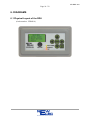
6.2 Layout Of RDU Front Panel
1
7
2
3
4
5
6
8
9
10
11
1
Liquid display unit (4 x 20)
7
Left key
2
Up key
8
Communication indication
3
Enter key
9
In service (motor run) indication
4
Right key
10
Trip indication
5
Reset / Menu key
11
Infra red link for MMI or PC to IrDA.
6
Down key
2
KD-RDU-420
Page 16 / 22
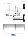
6.3 Layout Of RDU Back Panel
1
2
3
4
1
Communication to relay
3
Braked
2
Dongle key port
4
Power supply port
2
KD-RDU-420
Page 17 / 22
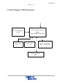
6.4 Block Diagram of RDU Display Unit
RS232 Communication
to relay
Dongle Key
Micro-controller Unit with
Memory
(Flash, EEPROM and RAM)
Keyboard
Infrared Interface
(IrDA)
Liquid Crystal Display
(4lines x 20characters)
KD-RDU-420
Page 18 / 22
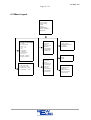
6.5 Menu Layout
MAIN MENU
1 Actual Values
2 Relay Settings
3 Faults
4 Events
5 MMI Settings
6 Relay Clock(RTC)
7 Relay Info
1. ACTUAL VALUES
1.1 I Load
1.2 TC level used
1.3 Vlev Vr
1.4 Vw Vb
1.5 EL
1.6 Unbalance
1.7 Volt Sym
1.8 Power factor
1.9 Ios Lock
1.10 Relay 1 (status)
1.11 Relay 2 (status)
3. FAULTS
3.1 View [Nr]
3.2 Status
3.3 Date & Time
3.4 Run Hr
3.5 Current(Max)
3.6 Voltage(Min)
3.7 Contact R.T.
6. RELAY CLOCK
4. EVENTS
2. SETTINGS
2.1
2.2
2.3
2.4
RDU Mem Slot
Copy Slot → Slot
DwnLd Slot → KX
UpLoad KX → Slot
5. MMI SETTINGS
5.1 Auto Scroll
5.2 Backlight Auto On
5.3 Contrast
5.4 Brightness
4.1 View [Nr]
4.2 Status
4.3 Date & Time
4.4 AlarmFlags
4.5 Trip Flag
4.6 Run Hr
4.7 Current(Max)
4.8 Voltage(Min)
4.9 Contact R.T.
6.1 Date
6.2 Time
7. RELAY INFO
7.1 Start Up Cntr
7.2 Trip Cntr
7.3 Motor Run Hrs
7.4 Drv Description
7.5 Drv File ID
KD-RDU-420
Page 19 / 22
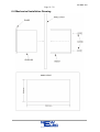
6.6 Mechanical Installation Drawing
KD-RDU-420
Page 20 / 22
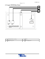
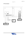
6.7 Wiring Diagram
Dongle
Key
(Optional)
Cable between
RDU and relay
110 / 220 Vac
Power Supply
KD-RDU-420
Page 21 / 22
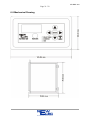
6.8 Mechanical Drawing
KD-RDU-420
Page 22 / 22
7. ACCESSORIES
When ordering FPR0218 all accessories will be included. But can be ordered separately.
7.1 RDU To Relay Communication Cable
Order information: NewElec RDU to relay communication cable (CAB0101)
7.2 NewElec RDU Dongle Key
Order information: NewElec RDU dongle key (CAB0027)
----ooOoo----