1
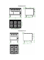
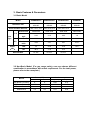
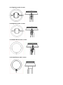
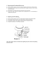
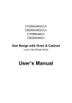
C9GRA4GVE1 C9GRA6GVE1 C9GRA4GVU1 C9GRA4E1 Gas Range Luxury Gas Range Series User’s Manual Dear Client & User, Firstly, thanks for purchasing and using our product. All the information and guidelines of this user’s manual comply with certain applicable regulations, which come out from our long-term accumulated knowledge and experience as well as current project development situations. Limited to some special structures, additional specified items or new technology changes, the actual usage situation might be some different from what stated in this user’s manual. Should you have any question, please do not hesitate to contact the manufacturer via the method shown in back cover page of this manual. For safety purpose and efficient operation, please make this document available to users for reference. Do have them to read this manual carefully before carry out any action on this device, especially when starting. The manufacturer declines any responsibility in the event users do not follow the instructions or guidelines stated here. The user’s manual should be placed close to the device, in convenience of users’ reading before operation. We have the full authority to reserve the further technical changes of the device, in the scope of further performance improvement characteristic development. Warning The appliance is only applicable to low-pressure gas. During using, users must use low-pressure gas pressure reducing valve instead of high or medium reducing valve. Any self-modification, wrong installation, adjustment or maintenance can lead to property loss or casualty. Please contact the manufacturer for any adjustment or maintenance, and have the work done by a trained & qualified person. For your safety sake, please keep the machine away from any liquid, gas or other object, which is flammable or explosive. For your safety sake,walls and countertops in the mounting position of the appliance should be made of refractory materials to ensure safety of the operators and safe operation of the appliance. Do not modify the air inlet and smoke vent required for combustion. Otherwise, it may cause safety accidents. This appliance is designed for food cooking. To avoid hazard, pay attention to the water level in pan, do not dry heat the utensil or let the food inside spill over. Fire warning: If you smell the gas, please keep away from any fire source. Do not light up any device or touch the electronic switch. Do not use any phone in the building either. Close the main gas valve immediately and call the professional personnel to maintain it. Control knob of the gas valve should be operated with hands only, do not use any tools to control the knob. If it cannot be rotated with hands, do not do it by force or attend to fix it. Operate by force or maintain improperly will lead to large gas leakage or deflagration easily. The manufacturer won’t bear any responsibility for fire accidents caused by improper operation or maintenance. Contents 1. Functional Introduction…………………………………………1 2. Structure Schematic Diagram……………………..…………..1 3. Basic Features & Parameters…………………………………4 4. Precautions & Recommendations…………………………….6 5. Working Instructions & Operation Flow………………………9 6. Routine Inspection………………………………………….…..11 7. Cleaning & Maintenance…………………………………….…11 8. Failure Analysis & Trouble Shooting……………………….…12 1. Functional Introduction This product is manufactured by our company, which is combined with advantage from home and abroad. It is novel in design, reasonable in structure, easy in operation, all stainless steel made, durable in using and convenient in maintenance. It is equipped with flame failure safety protection device. Also, the thermostatic control makes the temperature freely adjustable at a certain range according to food requirement. Therefore, it is the ideal equipment for hotel, supermarket, restaurant, western restaurant, fast food restaurant and food industry. 2. Structure Schematic Diagram C9GRA4GVE1 C9GRA6GVE1 C9GRA4GVU1 C9GRA4E1 3. Basic Features & Parameters 3.1 Basic Model Model C9GRA4GVE1 C9GRA4GVU1 C9GRA6GVE1 C9GRA4E1 Dimension mm 800×900× 850+60 800×900× 850+60 1200×900× 850+60 800×900× 850+60 Oven Chamber Size mm 540×670×275 540×670×275 540×670×275 Pressure Pa 2800-3200 2800-3200 2800-3200 2800-3200 Gas Cons. kg/h 2.92 2.16 4.33 1.6 Pressure Pa 2000 2000 2000 2000 4.09 3.37 6.07 2.54 LPG 35 25.8 51.8 19.2 NG 38.8 31.8 57.5 24 R1 3/4" R1 3/4" R1 3/4" R1 3/4" LPG Gas Type NG Gas Cons. m3/h Power (kW) Gas Inlet Size 3.2 Non-Basic Model: (For gas range mainly, user can choose different combination in accordance with actual requirement. For the total power, please refer to the nameplate.) Burner Power (KW) Gas Consumption NG LPG NG (M3/H) LPG (KG/H) Big Burner (2-crown) 9 9 0.95 0.75 Big Burner (1-crown) 7.5 5.6 0.79 0.47 Middle Burner 4.5 4 0.48 0.33 Small Burner 3.5 2.8 0.37 0.23 3.2.1 Big Burner with 2-crown 3.2.2 Big Burner with 1-crown 3.2.3 Middle Burner with 1-crown 3.2.4 Small Burner with 1-crown 4. Precautions & Recommendations 4.1 Transportation and Storage During transportation, the machine should be carefully handled and do not put it upside down to prevent from damaging to the shell and inside. The packaged machine should be stored in a ventilated warehouse without corrosive gas. If it needs to be stored in open air temporarily, measurement against raining is needed. 4.2 Notice for Installment 1. The appliance can be installed as a countertop type. Also you can dismantle the 4 legs, and then screw the body with the cabinet, but first you should have a matched cabinet. 2. 3. Take out the attached battery, turn the pulse button counterclockwise, then put in the battery in the correct direction as shown and tighten the pulse button. Components used for appliance connection should comply with provisions in gas 4. safety, installation and operation. The appliance should be installed separately or assembled with other device in stated 5. range. The appliance is not suitable for built-in installation, otherwise, the appliance may work in hypoxia condition, emission of the combustion products may be out of limits and it may cause health problems, even death. 6. The appliance should keep a minimum clearance of 10cm away from walls. Do not install the appliance on flammable floor or materials. If it is installed on the countertop, the countertop should be made of refractory materials to ensure safety of the 7. 8. 9. operators and normal operation of the appliance. During installation, please consider the weight of the appliance. It is advisable to install on the floor or countertop. The appliance should be installed in a well-ventilated area, if possible under a vent hood, in compliance with all applicable regulations in force. This will ensure that all burnt gases produced during the combustion process are completely exhausted. Otherwise, the accumulated waste gas may do harm to people’s health, even cause serious injuries or death. After installation, keep the appliance stable and level. Do not tilt or sway during operation. 10. Before installation, remove the outer plastic film first. Clean the residues on the stainless steel sheet with appropriate substance. 11. Check that the appliance is pre-set to use the gas family available at the place of installation. Make sure the supply gas is the same with the gas that the appliance allows to use. 12. Do not use gas that not applicable to the appliance as fuel, neither does high-pressure or medium-pressure regulating valve. (This appliance is only applicable to low-pressure regulating valve.) 13. Before installation, a quick acting disconnecting valve should be installed upstream the appliance where is easy to reach. 14. Making sure the applicable gas is the same as the supplied one. If not, stop using. 15. Pipeline connected to the appliance should be connected with a metal pipe fitting, and make sure that there is no leakage. 16. If the pressure of the gas pipeline is 15% higher or lower than the rated pressure the appliance required, a regulator should be installed to ensure it reaches the rated value. 17. After connecting the appliance to the gas system, check for leaks at joints and pipe fittings; to do so, use soapy water or a specific leak detector (spray). “No Flaming!” 18. Checking gas supply pressure after installation. Gas supply pressure can be measured with a liquid-filled pressure gauge (for example, a U-shaped pressure gauge, minimum scale division 0.1 mbar) or a digital gauge. Procedure as follows: Remove the panel, unscrew the screw on the pressure port (picture 2); Place the pressure gauge; Start up the appliance by following the instructions in the user’s manual; Check supply pressure; After the check, remove the pressure gauge; Replace the sealing screw. Sealing screw Pressure port Picture 2 4.3 Special Notice 1. The appliance in only designed for food cooking, not applicable to other uses. 2. The user’s manual includes all necessary information about installation, operation and maintenance. Please operate according to the specific instructions in the manual, making sure the appliance works in perfect performance. 3. Executive Standard: The appliance complies with the criteria in CJ/T28-2003 <Chinese Cooking Gas Appliance>. The appliance is certificated in quality and safety, whose code is XK21-007-00951. 4. The warranty remains valid only when the appliance is installed in accordance with precautions and local provisions involved. The manufacturer is not liable for loss caused by not observing these precautions. 5. Installation, initial use and maintenance should be done by professional or licensed personnel or franchised person approved by manufacturer. 6. During installation and maintenance, to ensure safety of operation, please carefully observe the following procedures. 7. Keep the user’s manual carefully for further reference or left for the next operator authorized to use the appliance. 8. Please keep the integrity of the appliance and remove the outer package. If you have any questions, consult specialist and stop using the appliance. To avoid danger, keep the packaging materials away from children. (For the materials are plastic bags, nails etc.) 9. This product is a commercial machine that needs to be operated by experienced technician. 10. Do not leave the appliance unattended. To avoid danger, turn it off if necessary. 11. Maintenance must be done by professional technicians with original accessories. If this requirement cannot be observed, it may affect the safety performance of the appliance. 12. This machine is only for commercial use, not applicable for other usages. Or, it may cause hazard. 13. Do not aim at the appliance with water jet during cleaning. That may damage the components, e.g. electrical equipment and control valve etc. 14. To prevent surface oxidation and chemical interaction, the stainless steel surfaces should be cleaned appropriately and regularly. 15. Perfect performance and longer service life of the appliance is guaranteed by correct installation, professional operation and continuous maintenance. 5. Working Instructions & Operation Flow 1. Control Knob: Fig.1 Fig.2 Fig.3 Fig.4 2. Ignition: Press down the control knob and rotate it counterclockwise to align “ ” with the zero salient point. At this time, hold the knob and push down the igniter simultaneously to light up the pilot flame. (Initial ignition may be a little longer due to the air existing in the pipeline. The pilot flame can be normally ignited when the air is exhausted completely.) After ignition, release the knob 20s later. Turn the knob to MAX or MIN according to food requirements. 3. Flameout: Press down the control knob and turn it clockwise to ●. Turn off the main gas supply. 4. Replacing the Main Nozzle(Picture 4): Have involved tools prepared. Dismantle the burner frame, gas ring, burner base and take out the basin, then remove the nozzle and substitute it with a matched one. Fasten the nozzle and replace the basin, burner base, gas ring and burner frame in order. As for oven, take apart the lower panel of the oven door and discharge the nut and nozzle holder with an appropriate spanner, then substitute with a matched nozzle. Fasten the nozzle and detect for leakage, then seal the panel. 5. Replacing the Pilot Nozzle(Picture 4): Place a proper spanner on the nut of the pilot support to balance the twisting stress. Discharge the screw fixing the thermocouple with a straight screwdriver, then remove the thermocouple. Discharge the nut fixing the aluminum pipe and remove the pipe. Remove the pilot nozzle and replace with an appropriate one. It is unnecessary to regulate the primary air. 6. Adjusting the Pilot Nozzle: Place a proper spanner on the nut of pilot support to balance the twisting stress. Discharge the bolts at bottom of the support with a straight screwdriver. Unscrew the screws in the support counterclockwise to adjust the flame. Regulate the primary air according to gas type. Note: Gas leakage must be checked after regulating the pilot nozzle and replacing the main nozzle. 6. Routine Inspection It is necessary to check the machine daily. Check the machine regularly can avoid serious accident happens. Stop using if user feels that there are some problems in the circuit or machine. Check the situation of the machine before or after using every day. Before using: Whether the machine is tilted? Whether the control panel is damaged? During using: Whether there is strange odor or vibration noise? Whether the burner flame is normal? Any light back or flameout? Whether the power is normal? 7. Cleaning & Maintenance 1. Before using, remove all commercial grease. Clean the superficial grease with a towel, then rinse it with mild detergent and water. Do not use abrasive detergent to clean the appliance surface, neither do scrape it with steel wire brush or sharp utensil, that may cause damage. 2. Do not spray the furnace surface with water directly, nor do clean it with corrosive 3. substance (acid, alkali). For burner cleaning, detergent remained on burner surface and in fire hole should be 4. removed completely. Otherwise, it may cause a short-time flameout or incomplete combustion, even affect the safety performance of the appliance or do harm to personnel health. If not going to use the appliance for a long period of time: cut off the gas supply; clean 5. 6. the furnace surface with a gasoline cloth; store it in a well-ventilated area. General inspection should be carried out at least once a year by professional personnel. 90% of the appliance is made of metal (stainless steel, iron, aluminum, galvanized metal sheet), which can be recycled by appointed treatment plant according to the environmental standards of the equipment installed countries in force. (No littering!) 8. Failure Analysis &Trouble Shooting Symptoms Causes 1. Solutions Pressure in gas pipeline is not enough. The pilot flame cannot be lit up. 2. 3. The nozzle is blocked. Connection of thermocouple 1. 2. Regulate the reducing valve. Unblock the nozzle. is loose. 3. Tighten the thermocouple. 4. The thermocouple is 4. Replace the thermocouple. 5. Replace the gas control valve. 5. defective. The gas control valve is Pressure in gas pipeline is not enough. 1. Regulate the reducing valve. 2. Main nozzle is blocked. 2. Unblock the nozzle. 3. The gas control valve is defective. 3. Replace the gas control valve. defective. 1. The pilot flame is on but the main burner cannot be lit up. 1. Nozzle diameter does not match with the gas supply. It has a light-back sound when turning off the valve. 2. The damper is too large. 3. The supply pressure is too low. 4. Flow of connected pipe is not 1. Regulate the nozzle diameter. 2. Adjust the damper. 3. Regulate the reducing valve. 4. Increase the permitted flow. enough. It has red flame and black smoke. 1. Nozzle diameter does not match with the gas supply. 2. The damper is too small. 3. Gas nearly runs out. 4. Gas ingredients are volatile in gas peak period. 1. Regulate the nozzle diameter. 2. Adjust the damper. 3. Replace the gas. 4. Decrease the gas Increase it after the peak. Aforementioned troubles are just for reference. If any failure occurs, please stop using and inform the professional technicians to check and repair. Safety is first and maintenance should be done after shutting down the power supply and gas supply. flow.