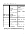
1
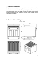
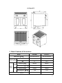
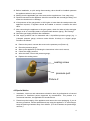
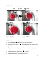
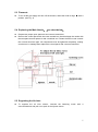
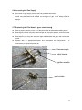
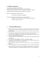
C7GLR71 C9GLR81 Gas Lava Rock Grill with Cabinet Luxury Gas Range Series User’s Manual Dear Client & User, Firstly, thanks for purchasing and using our product. All the information and guidelines of this user’s manual comply with certain applicable regulations, which come out from our long-term accumulated knowledge and experience as well as current project development situations. Limited to some special structures, additional specified items or new technology changes, the actual usage situation might be some different from what stated in this user’s manual. Should you have any question, please do not hesitate to contact the manufacturer via the method shown in back cover page of this manual. For safety purpose and efficient operation, please make this document available to users for reference. Do have them to read this manual carefully before carry out any action on this device, especially when starting. The manufacturer declines any responsibility in the event users do not follow the instructions or guidelines stated here. The user’s manual should be placed close to the device, in convenience of users’ reading before operation. We have the full authority to reserve the further technical changes of the device, in the scope of further performance improvement characteristic development. Warning Any self-modification, wrong installation, adjustment or maintenance can lead to property loss or casualty. Please contact the manufacturer for any adjustment or maintenance, and have the work done by a trained & qualified person. For your safety sake, please keep the machine away from any liquid, gas or other object, which is flammable or explosive. For your safety sake,walls and countertops in the mounting position of the appliance should be made of refractory materials to ensure safety of the operators and safe operation of the appliance. This appliance should not be operated by those who have physiological, perceptual or mental disabilities or those who have insufficient experience or knowledge (including children). Only in conditions of being given sufficient supervise & guarantee of personal safety, as well as proper instructions & guidance, those who were mentioned above can make some particular operation of this device. Keep children away from the device. Preserve this manual safely. When passing on/selling the device to a third party, the manuals must be handed over along with the device. All users must operate the device complying with the user’s manual and related safety guidelines. The appliance should be installed in a well-ventilated area, if possible under a vent hood, in compliance with all applicable regulations in force. This will ensure that all burnt gases produced during the combustion process are completely exhausted. To prevent occurrence of safety accidents, please do not modify the air inlet and smoke vent required for combustion! The appliance is only applicable to low-pressure gas regulating valve. It may cause property loss or safety accidents if high or medium pressure regulating valve is used. Fire warning: If you smell the gas, please keep away from any fire source. Do not light up any device or touch the electronic switch. Do not use any phone in the building either. Close the main gas valve immediately and call the professional personnel to maintain it. Operate by force or maintain improperly will lead to large gas leakage or deflagration easily. The manufacturer won’t bear any responsibility for fire hazard caused by improper operation or maintenance. Contents 1. Functional Introduction...................................................1 2. Structure Schematic Diagram........................................1 3. Basic Features & Parameters........................................2 4. Precautions & Recommendations..................................3 5. Working Instructions & Operation Flow..........................5 6. Routine Inspection.........................................................9 7. Cleaning & Maintenance................................................9 8. Failure Analysis & Trouble Shooting..............................10 1. Functional Introduction This product is manufactured by our company, which is combined with advantages from home and abroad. It is novel in design, reasonable in structure, easy in operation, durable in using and convenient in maintenance. Equipped with high efficient European burners, flame failure protection devices, pilot standby, continuous pulse ignition device. Therefore, it is the ideal equipment for hotel, supermarket, restaurant, western restaurant, fast-food restaurant and food industry. 2. Structure Schematic Diagram C9GLR81 1 C7GLR71 3. Basic Features & Parameters Model C9GLR81 C7GLR71 Dimension(mm) 800×900×850+60 700×700×850+60 LPG 17 14.4 NG 17 14.4 Pressure(Pa) 2800Pa 2800Pa Consumption(Kg/h) 1.4 1.19 Pressure(Pa) 2000pa 2000pa Consumption(M³/h) 1.80 1.52 80 / Power(kW) LPG Gas Type NG Net Weight(kg) 2 4. Precautions & Recommendations 4.1 Transportation and Storage During transportation, the machine should be carefully handled and do not put it upside down to prevent from damaging to the shell and inside. The packaged machine should be stored in a ventilated warehouse without corrosive gas. If it needs to be stored in open air temporarily, measurement against raining is needed. 4.2 Notice for Installment 1. Installation should be done by professional technician. 2. Take out the attached battery, turn the pulse button counterclockwise, then put in the battery in the correct direction as shown and tighten the pulse button. 3. Components used for appliance connection should comply with provisions in gas safety, installation and operation. 4. The appliance should be installed separately or assembled with other devices in accordance with provisions. 5. The appliance is not suitable for built-in installation, otherwise, the appliance may work in hypoxia condition, emission of the combustion products may be out of limits and it may cause health problems, even death. 6. The appliance should keep a minimum clearance of 10cm away from non-combustible objects (e.g. walls, windows etc) on both sides, and 20cm at its back. Do not install the appliance on flammable floor or materials. If it is installed on the countertop, the countertop should be made of refractory materials to ensure safety of the operators and safe operation of the appliance. 7. During installation, please consider the weight of the appliance. It is advisable to install on the floor or a countertop. 8. The appliance should be installed in a well-ventilated area, if possible under a vent hood, in compliance with all applicable regulations in force. This will ensure that all burnt gases produced during the combustion process are completely exhausted. Otherwise, the accumulated waste gas may do harm to people’s health, even cause serious injuries or death. 9. After installation, keep the appliance stable and level. Do not tilt or sway during operation. 10. Before installation, remove the outer plastic films. 11. Check that the appliance is pre-set to use the gas family available at the place of installation. Make sure the supply gas is the same with the gas that the appliance allows to use. 12. Do not use gas that not applicable to the appliance as fuel, neither does high-pressure or medium-pressure regulating valve. (This appliance is only applicable to low-pressure regulating valve.) 3 13. Before installation, a quick acting disconnecting valve should be installed upstream the appliance where is easy to reach. 14. Making sure the applicable gas is the same as the supplied one. If not, stop using. 15. Pipeline connected to the appliance should be connected with a metal pipe fitting, and make sure that there is no leakage. 16. If the pressure of the gas pipeline is 10% higher or lower than the rated pressure the appliance required, a regulator should be installed to ensure it reaches the rated value. 17. After connecting the appliance to the gas system, check for leaks at joints and pipe fittings; to do so, use soapy water or a specific leak detector (spray). “No Flaming!” 18. Check the gas supply pressure after installation. 19. Gas supply pressure can be measured with a liquid-filled pressure gauge (e.g. a U-shaped pressure gauge, minimum scale division 0.1mbar) or a digital gauge. Procedure as follows: Remove the panel, unscrew the screw on the pressure port (Picture 2); Place the pressure gauge; Start up the appliance by following the instructions in the user’s manual; Check the supply pressure; After the check, remove the pressure gauge; Replace the sealing screw. sealing screw pressure port Picture 2 4.3 Special Notice 1. 2. Installation, initial use and maintenance should be done by professional or licensed personnel or franchised person approved by manufacturer. This product is a commercial machine, not applicable for household use. Please keep the integrity of the appliance and remove the outer packaging. If you do have any questions, call the specialist and stop using the appliance. To avoid danger, keep the packing materials away from children. (For the materials are plastic bags, nails etc.) 4 3. For initial use, the duration of ignition may be a little longer due to the air existing in the new pipeline. If it cannot be lit up for the first time, turn the ignition switch off and turn it on 3 minutes later to prevent from deflagration. 4. To avoid hazard, turn the appliance off if not going to used it or if it is unattended. 5. This product is only for commercial use, not suitable for other uses, or it may cause 6. danger. This appliance is only designed for meat grilling, not applicable for other uses. 7. Do not sway or tilt the appliance during operation. 8. 9. Do not dismantle or self-modify the appliance. Dismantlement and self-modification may cause casualty. 10. Do not pat the product or put any heavy objects onto it. 11. Abnormal operation may lead to appliance damage and danger. 12. High temperature may cause scald. Do not touch the appliance directly with hands due to high temperature during or after operation. Surfaces of chute grate and coaming is hot, do not touch with your hands. Caution burn! 13. Do not destroy the control panel with hard or sharp objects. 14. Do not aim at the appliance with water jet during cleaning, that may damage the electrical equipment or control valve etc. 15. To prevent surface oxidation and chemical interaction, the stainless steel surfaces should be cleaned appropriately and regularly. To clean the chute grate, take it off for cleaning. 16. Perfect performance and longer service life of the appliance is guaranteed by correct installation, professional operation and continuous maintenance. 17. This appliance is verified by laboratory, satisfactory performance is guaranteed. To save energy, please avoid operating the appliance in circumstance of not cooking food or in bad performance. 5. Working Instructions & Operation Flow 1. Put the cast iron plain grate on the grill first, then fill the grate with lava rocks and install the chute grate to determined position. Pay attention that the semi-circle side of the chute grate should be fixed on the stainless steel cylinder. 2. Two ways for chute grate positioning: flat and tilted. Position the chute grate by putting the slot into the round steel according to your requirement. Before cooking, heat the appliance for no less than half an hour to preheat the lava rocks and chute grate. Lava rocks and cast iron are provided with heat saving function. 5 5.1 Control Panel: Graphical Representation knob fire hole pulse igniter Fig. 4:●OFF Fig. 5: IGN Fig. 6: Fig.7: MAX MIN 5.2 Knob Control: Turn the knob to align ● with 0 position. The valve is OFF. (see Fig. 4) Press the knob and rotate it to , simultaneously press down the pulse igniter. (see Fig. 5) (Initial duration of ignition may be a little longer due to the air existing in the pipeline. The pilot flame cannot be lit up normally until the air is exhausted completely.) After ignition, release the knob. To work in MAX power, turn the knob to To work in MIN power, turn the knob to . (see Fig. 6) . (see Fig. 7) 6 5.3 Flameout: To cut off the gas supply and turn off the burners, rotate the knob to align ● with 0 position. (see Fig. 4) 5.4 Replacing the Main Nozzle:(see chart below) Prepare two proper open spanners and a cross-screwdriver. Remove the control panel with the cross-screwdriver, then discharge the nozzle with the two spanners and replace it with a matched one. Fasten the flat nut and connect the nut and aluminum pipe. All components must be tightened completely, making sure there is no leakage then replace the control panel with a cross-screwdriver. 5.5 Regulating the Air Inlet: To regulate the air inlet volume, unscrew the fastening screw with a cross-screwdriver and pull out or push in the injector sleeve. 7 5.6 Converting the Gas Supply Conversion of gas supply must be done by qualified technicians. This product is applicable for all gas sources. To convert the gas, just to replace a nozzle and pilot nozzle that suitable for such type of gas. Other fittings need no change. 5.7 Replacing the Pilot Nozzle:(see chart below) Place a proper spanner on the nut of the pilot nozzle to balance the twisting stress. Discharge the screw fixing the thermocouple with a proper spanner, and remove the thermocouple. Discharge the nut fixing the aluminum pipe and dismantle the pipe, then remove the nozzle. Replace with an appropriate nozzle and reassemble the components. It is unnecessary to adjust the primary air. thermocouple pilot burner ignition needle ; pilot nozzle 8 6. Routine Inspection It is necessary to check the machine daily. Check the machine regularly can avoid serious accident happens. Stop using if user feels that there are some problems in the circuit or machine. Check the situation of the machine before or after using every day. Before using: Whether the machine is tilted? Whether the control panel is damaged? During using: Whether there is strange odor or vibration noise? Whether the burner flame is normal? Any light back or flameout? Whether the power is normal? 7. Cleaning & Maintenance 1. 2. Before using, take off the chute grate to clean. Remove the dirt on the cast-iron surface with a nylon brush, then clean the grate with mild detergent and water, wipe it up with a cloth. Do not clean the furnace surfaces with abrasive detergent, neither does scrape it with steel wire brush or sharp utensil. Otherwise, it may damage the grate surface. 3. Do not aim at the appliance surface with water directly, neither does clean it with corrosive substances (Hydrochloric acid). 4. To prevent occurrence of safety accident, do not modify the air inlet volume required for combustion. If not going to use the appliance at any time, cut off the gas supply. If not going to use the appliance for a long period of time, clean its surfaces with a 5. 6. 7. 8. gasoline cloth and store it in a well-ventilated area. General inspection should be carried out at least once a year by professional personnel. 90% of the appliance is made of metal (stainless steel, iron, aluminum, galvanized metal sheet), which can be recycled by appointed treatment plant according to the environmental standards of the equipment installed countries in force. (No littering!) 9 8. Failure Analysis & Trouble Shooting Symptoms Causes 1. 2. Solutions The igniter does not work. Plug or plug cord of igniter is damaged. The pilot flame cannot be lit up. 3. Pressure in gas pipeline is 4. 5. not enough. The pilot nozzle is blocked. Connection of thermocouple 6. is loose. The thermocouple is defective. 7. 1. If it is a pulse igniter, replace the battery. 2. Replace relevant fittings. 3. 4. Regulate the reducing valve. Unblock the nozzle. 5. 6. 7. Tighten the thermocouple. Replace the thermocouple. Replace the gas control valve. The gas control valve is defective. 1. The pilot flame is on but the main burner cannot be lit up. It has a light-back sound when turning off the valve. not enough. 2. 3. Main nozzle is blocked. The gas control valve is defective. 1. Air inlet injected by damper is too much. 1. 2. Regulate the reducing valve. Unblock the nozzle. 3. Replace valve. 1. Regulate the primary air the gas control 2. Nozzle diameter does not 2. 3. match with the gas supply. The supply pressure is too Regulate diameter. low. Flow of connected pipe is not enough. 3. 4. Regulate the reducing valve. Increase the permitted flow. Air inlet injected by damper is little. Nozzle diameter does not match with the gas supply. 1. Regulate the primary air inlet. Regulate the nozzle diameter. Gas ingredients are volatile in gas peak period. 3. 4. 1. It has red flame and black smoke. Pressure in gas pipeline is 2. 3. inlet. 2. the nozzle Decrease the gas flow. Increase it after the peak. Aforementioned troubles are just for reference. If any failure occurs, please stop using and inform the professional technicians to check and repair. Safety is first and maintenance should be done after shutting down the power supply and gas supply. 10