1
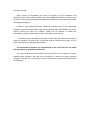
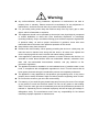
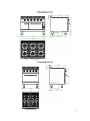
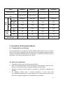
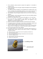
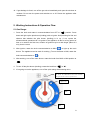
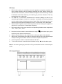
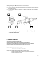
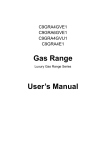
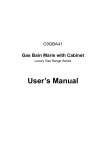
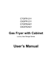
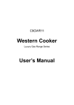
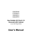
C7GRA4/6GVU1 C9GRA4/6GVU1 C7GRA4/6U1 C9GRA4/6U1 Gas Range with Oven & Cabinet Luxury Gas Range Series User’s Manual Dear Client & User, Firstly, thanks for purchasing and using our product. All the information and guidelines of this user’s manual comply with certain applicable regulations, which come out from our long-term accumulated knowledge and experience as well as current project development situations. Limited to some special structures, additional specified items or new technology changes, the actual usage situation might be some different from what stated in this user’s manual. Should you have any question, please do not hesitate to contact the manufacturer via the method shown in back cover page of this manual. For safety purpose and efficient operation, please make this document available to users for reference. Do have them to read this manual carefully before carry out any action on this device, especially when starting. The manufacturer declines any responsibility in the event users do not follow the instructions or guidelines stated here. The user’s manual should be placed close to the device, in convenience of users’ reading before operation. We have the full authority to reserve the further technical changes of the device, in the scope of further performance improvement characteristic development. Warning Any self-modification, wrong installation, adjustment or maintenance can lead to property loss or casualty. Please contact the manufacturer for any adjustment or maintenance, and have the work done by a trained & qualified person. For your safety sake, please keep the machine away from any liquid, gas or other object, which is flammable or explosive. This appliance should not be operated by those who have physiological, perceptual or mental disabilities or those who have insufficient experience or knowledge (including children). Only in conditions of being given sufficient supervise & guarantee of personal safety, as well as proper instructions & guidance, those who were mentioned above can make some particular operation of this device. Keep children away from the device. Preserve this manual safely. When passing on/selling the device to a third party, the manuals must be handed over along with the device. All users must operate the device complying with the user’s manual and related safety guidelines. If this appliance is placed near walls, partitions or kitchen furniture and the like, it is advisable to make these facilities with non-combustible material, otherwise cover them with non-combustible heat-resistant material, and pay attention to fire prevention regulations. The appliance should be installed in a well-ventilated area, if possible under a vent hood, in compliance with all applicable regulations in force. This will ensure that all burnt gases produced during the combustion process are completely exhausted. The appliance is only applicable to low-pressure gas regulating valve. It may cause property loss or safety accidents if high or medium pressure regulating valve is used. Do not seal the screw on gas valve with seal welding. Fire warning: If you smell the gas, please keep away from any fire source. Do not light up any device or touch the electronic switch. Do not use any phone in the building either. Close the main gas valve immediately and call the professional personnel to maintain it. Operate by force or maintain improperly will lead to large gas leakage or deflagration easily. The manufacturer won’t bear any responsibility for fire hazard caused by improper operation or maintenance. Contents 1. Functional Introduction…………………………………………1 2. Structure Schematic Diagram……………………..…………..1 3. Basic Features & Parameters…………………………………4 4. Precautions & Recommendations…………………………….5 5. Working Instructions & Operation Flow………………………8 6. Routine Inspection………………………………………….…..12 7. Cleaning & Maintenance…………………………………….…13 8. Failure Analysis & Trouble Shooting……………………….…14 1. Functional Introduction This product is manufactured and developed by our company, which is combined with advantage from home and abroad. It is novel in design, reasonable in structure, easy in operation, durable in using and convenient in maintenance. Therefore, it is the ideal equipment for food industry. 2. Structure Schematic Diagram C7GRA6GVU1 1 C7GRA6U1 C9GRA4GVU1 2 C9GRA6GVU1 C7GRA4GVU1 3 Structural & Functional Features: 1. The support, external finishing and adjustable feet are stainless steel made. 2. Control panel with convenient design, with control switches inclined to operators. 3. Equipped with 4 or 6 cast-iron burners. If the burners go off accidentally, the safety valve with thermocouple will shut down immediately. Also, provided with 4 or 6 black cast-iron burner frame and stainless steel crumb pan. 4. Adjustable oven temperature: 120℃-330℃. 5. Tubular burners of 5.8kW, with flame self-stable function. If the burner goes off accidentally, it will turn off automatically. 6. The enamel baseboard, removable, high radioactive and heat-resistant. 3. Basic Features & Parameters Model C7GRA4GVU1 C9GRA4GVU1 C7GRA6GVU1 C9GRA6GVU1 Dimension mm 700×700×850+60 800×900×850+60 1050×700×850+60 1200×900×850+60 Oven Chamber Size mm 560×700×275 560×700×275 2800-3200 2800-3200 2800-3200 2800-3200 Gas Cons. kg/h 2.16 2.16 3 2.44 Pressure Pa 2000 2000 2000 2000 Gas Cons. m3/h 3.37 3.37 4.75 3.48 LPG 25.8 25.8 35.8 35.8 NG 31.8 31.8 44.8 44.8 R1 3/4" R1 3/4" R1 3/4" R1 3/4" Gas Type L P G N G Power (kW) Pressure Pa Gas Inlet Size 4 Model C7GRA4U1 C9GRA4U1 C7GRA6U1 C9GRA6U1 Dimension mm 700×700×850+60 800×900×850+60 1050×700×850+60 1200×900×850+60 Oven Chamber Size mm 560×700×275 560×700×275 2800-3200 2800-3200 2800-3200 2800-3200 1.68 1.68 2.52 2.52 2000 2000 2000 2000 2.76 2.76 4.14 4.14 LPG 20 20 30 30 NG 26 26 39 39 R1 3/4" R1 3/4" R1 3/4" R1 3/4" Pressure L Gas Pa P G Gas Cons. kg/h Type Pressure N Pa G Gas Cons. m3/h Power (kW) Gas Inlet Size 4. Precautions & Recommendations 4.1 Transportation and Storage During transportation, the machine should be carefully handled and do not put it upside down to prevent from damaging to the shell and inside. The packaged machine should be stored in a ventilated warehouse without corrosive gas. If it needs to be stored in open air temporarily, measurement against raining is needed. 4.2 Notice for Installment 1. Installation should be done by professional technician. 2. Take out the attached battery, turn the pulse button counterclockwise, then put in the battery in the correct direction as shown and tighten the pulse button. 3. Appliance connection should conform to provisions in gas safety, installation and operation. The appliance should keep a minimum clearance of 10cm away from non-combustible substance (e.g. walls, windows etc.) on both sides, and 20cm at its back. Do not install the appliance on flammable floor or materials. 4. 5 5. During installation, please consider the weight of the appliance. It is advisable to 6. install on the floor. Position the appliance with a level gauge. Height of the appliance can be regulated by the adjustable feet. 7. The appliance should be installed in a well-ventilated area, if possible under a vent hood, in compliance with all applicable regulations in force. This will ensure that all burnt gases produced during the combustion process are completely exhausted. 8. After installation, keep the appliance stable and level. Do not tilt or sway during 9. operation. Before installation, a quick acting disconnecting valve should be installed upstream the appliance where is easy to reach. 10. Making sure the applicable gas is the same as the supplied one. If not, stop using. 11. Do not use gas that not applicable to the appliance as fuel, neither does high-pressure or medium-pressure regulating valve. (This appliance is only applicable to low-pressure regulating valve.) 12. Pipeline connected to the appliance should be connected with proper metal pipe. 13. If the pipeline pressure is 10% higher or lower than the rated pressure, please install a pressure regulator to adjust the gas pressure to reach the rated one. 14. After connecting the appliance to the gas system, check for leaks at joints and pipe fittings; to do so, use soapy water or a specific leak detector (spray). “No Flaming!” 15. Check the gas supply pressure after installation. 16. Gas supply pressure can be measured with a liquid-filled pressure gauge (e.g. a U-shaped pressure gauge, minimum scale division 0.1mbar) or a digital gauge. Procedure as follows: Remove the panel, unscrew the screw on the pressure port (Picture 2); Place the pressure gauge; Start up the appliance by following the instructions in the user’s manual; Check the supply pressure; After the check, remove the pressure gauge; Replace the sealing screw. sealing screw pressure port Picture 2 6 4.3 Special Notice 1. Installation, initial use and maintenance should be done by professional or licensed personnel or franchised person approved by manufacturer. This product is a commercial machine, not applicable for household use. 2. 3. Please keep the integrity of the appliance and remove the outer packaging. If you do have any questions, call the specialist and stop using the appliance. To avoid danger, keep the packing materials away from children. (For the materials are plastic bags, nails etc.) For initial use, the duration of ignition may be a little longer due to the air existing in the new pipeline. If it cannot be lit up for the first time, turn the ignition switch off and turn it on 3 minutes later to prevent from deflagration. 4. Do not use gas that not applicable to the appliance as fuel, neither does high-pressure or medium-pressure regulating valve. Making sure the applicable gas is the same as the supplied one, if not, stop using. 5. Do not leave the appliance unattended during operation. To avoid hazard, turn the appliance off if not going to used it or if it is unattended. 6. This product is a commercial machine that needs to be operated by trained personnel, 7. not applicable for household use. This product is only for commercial use, not suitable for other uses, or it may cause danger. 8. Do not sway or tilt the appliance during operation. 9. Do not dismantle or self-modify the appliance. Dismantlement and self-modification may cause casualty. 10. Do not pat the product or put any heavy objects onto it. Do not place any objects in the vent of the gas heater. Obstruction of smoke exhaustion may do harm to health. Abnormal operation may cause appliance damage and danger. 11. High temperature may cause scald. Do not touch the appliance directly with hands due to high temperature during or after operation. To prevent scald, cool down the appliance before moving it. 12. Do not aim at the appliance with water jet during cleaning. 13. To prevent surface oxidation and chemical interaction, the stainless steel surfaces should be cleaned appropriately and regularly. 14. Do not destroy the control panel with hard or sharp objects. 15. If any failure or anomaly occurs, turn off the main gas valve upstream the appliance and call the supplier to repair. 16. The appliance is made from recyclable materials, not containing any harmful or toxic substance. When dealing with the appliance and its packaging materials, please observe the local regulation in force strictly. The packaging materials should be classified and sent to an appointed collection site, making sure that complies with the local environmental protection regulation. 17. Do not place flammable substance (e.g. towel etc.) on anywhere of the furnace surface, otherwise, it may cause fire hazard. 18. After working, turn off the gas valve immediately. 7 19. If gas leakage is found, turn off the gas valve immediately and open the windows to ventilate. Do not turn the power and switches on or off. Reuse the appliance after maintenance. 5. Working Instructions & Operation Flow 5.1 Gas Range: 1. Press the knob and rotate it counterclockwise from OFF to “ ” position. Press down and light up the pilot burner (kindling) with an igniter. Hold pressing for 20s and observe that whether the pilot burner (kindling) is lit up. If not, repeat the aforementioned operations till it is ignited. If the appliance is idle for a long period of time or is used for the first time, duration of ignition may be a little longer (about 2-3 min), that is normal. 2. After ignition, rotate the knob counterclockwise to MAX “ ” to light up the main burner. The appliance can be used for cooking. (To turn the flame to MIN, rotate the knob counterclockwise to “ ”.). 3. After working, turn off the main burner: rotate the knob from MAX or MIN position to “ ”. 4. To turn off the pilot burner (kindling): rotate the knob from “ ” to “●”. 5. If not going to use the appliance, turn off the quick acting disconnecting valve. It will be OFF when the red needle aligns with the 0 position. ignition MAX MIN 8 5.2 Oven: 1. Before initial cooking, it is advisable to clean the appliance completely, especially the oven chamber. Remove all the packaging materials and films. Before cleaning the stainless steel accessories, make sure that the detergent used for cleaning is suitable 2. for stainless steel surface cleaning, not containing any corrosive substance. Then dry the appliance with a clean cloth. For initial use, it is normal that unpleasant odor is smelled. (Making sure that it is not caused by gas leakage.) Actually, it is caused by overheating of insulating materials and oil residue during the heating process of metal. When first using, leave the oven chamber empty and set the temperature to 330℃ to heat till the odor is eliminated. 3. Initial duration of ignition may be a little longer due to the air existing in the pipeline. It 4. cannot be lit up until the air is exhausted completely. Each knob position of the oven stands for corresponding chamber center temperature: 120℃, 190℃, 260℃, 330℃. 5. Press the knob and rotate it counterclockwise to align “ ” with salient point, press down the ignition button simultaneously. 6. 7. Observe the pilot flame via the visual window on the lower plate of the chamber. After ignition, hold pressing the knob for no less than 20s to heat up the thermocouple. If the pilot flame goes off when the knob is released, repeat the operations. 8. Oven temperature shall be controlled between 120-330℃. 9. To turn off the burners: rotate the knob clockwise to align “●” with the salient point. Note:To convert the gas supply from NG to LPG, just substitute the main nozzle and pilot nozzle. 5.3 Control Panel: 9 5.4 Replacing the Burner Nozzle:(see chart below: burner specification) Remove the burner frame, flame spreader and drip pan. Discharge the screw fixing the primary air damper, then remove the damper. Dismantle the nozzle with a spanner and substitute with a suitable one. 5.5 Replacing the Pilot Nozzle:(see chart below) Discharge the sealing screw with a spanner. Remove the nozzle with a straight screwdriver. Substitute with a suitable nozzle and fasten it. The pilot flame should be blue. And it shall surround the thermocouple. Otherwise, check that whether the nozzle is a correct one. 10 5.6 Replacing the Oven Nozzle:(see chart below) Discharge the screw and remove the lower front panel. Open the oven door and take out the lower panel. Remove the nozzle with a spanner and substitute with a suitable one. 5.7 Replacing the Oven Pilot Nozzle:(see chart below) Place a spanner on the pilot nozzle to balance the twisting stress. Discharge the screw fixing the thermocouple with a spanner, then remove the thermocouple. Discharge the nut fixing the gas pipeline, then remove the pipeline. Remove the pilot nozzle and substitute with a suitable one. It is unnecessary to adjust the primary air. 11 5.8 Regulating the MIN Output:(see chart below) For LPG, remove the knob and adjust the screw with a screwdriver via the small hole to regulate the flame. For other gases, adjust the screw till the flame is stable and even according to requirement. 10 13 11 12 10. screw for MIN output 12. thermocouple pipeline fitting 14 11. gas inlet pipe fitting 13. gas outlet pipe fitting 14. pilot flame pipeline fitting 6. Routine Inspection It is necessary to check the machine daily. Check the machine regularly can avoid serious accident happens. Stop using if user feels that there are some problems in the circuit or machine. Check the situation of the machine before or after using every day. Before using: Whether the machine is tilted? Whether the control panel is damaged? During using: Whether there is strange odor or vibration noise? Whether the burner flame is normal? Any light back or flameout? Whether the power is normal? 12 7. Cleaning & Maintenance 1. Before cleaning, turn off the appliance and the gas supply valve upstream. 2. Clean the burners and crumb pan regularly. 3. Clean the stainless steel surfaces with warm soapy water everyday, and rinse it 4. completely. (Do not aim at the appliance with squirt gun directly during cleaning.) During cleaning, do not clean the stainless steel surfaces with abrasive detergent, brush or scraper etc. Scraps may cause rusting. Rub according to the satin direction. Do not clean the steel surfaces with chlorine products (bleach, hydrochloric acid etc.) though such products are dilute. 5. Do not clean the floor where the appliance located with corrosive substance (e.g. KCL). 6. Clean the dirt on burners and baffle regularly. 7. Do not modify the ventilated space required for combustion. 8. Accumulation of Iron substance (e.g. substance formed by iron rust dissolving in the water of the pipeline, especially when the appliance is idle for a long period of time.) Therefore, to avoid such accumulation, do not clean the most stubborn food residue with steel wool brush. Instead, use a scraper or brush that made from stainless steel and not containing iron. 9. Accumulation of acidic substance, e.g. vinegar, lemon juice, spices, salt etc. Thus, avoid contacting the stainless steel accessories with such substances in long time. Steam of acid solution is extremely harmful to the appliance surfaces. 10. Perfect running condition and longer service life are guaranteed by a complete cleaning of the appliance everyday. Clean the appliance with a wet towel containing soapy water or detergent, rinse it with clear water and dry it with a clean cloth. Do not clean the appliance with steel wool brush, that may leave rusting. For the same reason, do not touch the appliance with iron articles. 11. Stains and abrasion on stainless steel surfaces: remove the scrape and black stains with artificial sponge. During cleaning, comply with the polishing direction. 12. Rusting: To remove the rusting, if necessary, contact the manufacturer of industrial detergent to find an appropriate detergent. Also, industrial rust removal products may do. After cleaning,rinse with clear water. If necessary, neutralize the residual acid chemical compound with alkaline detergent. 13. To avoid occurrence of rust stains, make sure that the salt residue on walls internally or externally is removed. 14. After cleaning, fire hole of burner should be out of obstruction. Otherwise, it may cause short-time incomplete combustion. 15. If not going to use the appliance at any time, turn off the gas valve upstream the appliance or the main power switch. 16. If not going to use the appliance for a long period of time, clean the stainless steel surface with a gasoline cloth. Then clean the appliance completely and store it in a well-ventilated warehouse without any corrosive gases. 13 17. 90% of the appliance is made of metal (stainless steel, iron, aluminum, galvanized metal sheet), which can be recycled by appointed treatment plant according to the environmental standards of the equipment installed countries in force. (No littering!) 8. Failure Analysis &Trouble Shooting Symptoms Causes 1. Solutions Pressure in gas pipeline is not enough. The pilot flame cannot be lit up. 1. Regulate the reducing 2. The nozzle is blocked. 3. Connection of thermocouple is loose. 2. 3. Unblock the nozzle. Tighten the thermocouple. 4. The is 4. Replace the thermocouple. 5. 5. defective. The gas control valve is Replace the gas control valve. thermocouple valve. defective. 1. Pressure in gas pipeline is not enough. 1. Regulate valve. the main burner cannot 2. Main nozzle is blocked. 2. Unblock the nozzle. be lit up. 3. The gas control valve is defective. 3. Replace the gas control valve. The pilot flame is on but 1. Nozzle diameter does not match with the gas supply. It has a light-back sound when turning off the gas supply. 2. The damper is too large. 3. The supply pressure is too low. 4. Flow of connected pipe is not enough. It has red flame and black smoke. 1. Regulate the reducing the nozzle diameter. 2. Adjust the damper. 3. Regulate the reducing valve. 4. Increase the permitted flow. 1. Nozzle diameter does not match with the gas supply. 1. Regulate diameter. 2. The damper is too small. 3. Gas nearly runs out. 4. Gas ingredients are volatile in 2. Adjust the damper. 3. Replace the gas. 4. Decrease the gas flow. gas peak period. the nozzle Increase it after the peak. Aforementioned troubles are just for reference. If any failure occurs, please stop using and inform the professional technicians to check and repair. Safety is first and maintenance should be done after shutting down the power supply and gas supply. 14